EP3736822A1 - Solid electrolyte material and battery - Google Patents
Solid electrolyte material and battery Download PDFInfo
- Publication number
- EP3736822A1 EP3736822A1 EP18898242.5A EP18898242A EP3736822A1 EP 3736822 A1 EP3736822 A1 EP 3736822A1 EP 18898242 A EP18898242 A EP 18898242A EP 3736822 A1 EP3736822 A1 EP 3736822A1
- Authority
- EP
- European Patent Office
- Prior art keywords
- solid electrolyte
- electrolyte material
- positive electrode
- battery
- negative electrode
- Prior art date
- Legal status (The legal status is an assumption and is not a legal conclusion. Google has not performed a legal analysis and makes no representation as to the accuracy of the status listed.)
- Pending
Links
- 239000007784 solid electrolyte Substances 0.000 title claims abstract description 183
- 239000000463 material Substances 0.000 title claims abstract description 139
- 238000002441 X-ray diffraction Methods 0.000 claims abstract description 29
- 229910052794 bromium Inorganic materials 0.000 claims abstract description 15
- 229910002483 Cu Ka Inorganic materials 0.000 claims abstract description 12
- 230000005855 radiation Effects 0.000 claims abstract description 9
- 239000013078 crystal Substances 0.000 claims description 27
- 239000003792 electrolyte Substances 0.000 claims description 15
- 150000001450 anions Chemical class 0.000 claims description 6
- 229910052801 chlorine Inorganic materials 0.000 abstract description 14
- 239000010410 layer Substances 0.000 description 47
- 239000002245 particle Substances 0.000 description 42
- 150000002500 ions Chemical class 0.000 description 30
- 238000000034 method Methods 0.000 description 30
- 230000000052 comparative effect Effects 0.000 description 23
- 239000007774 positive electrode material Substances 0.000 description 21
- 239000000843 powder Substances 0.000 description 21
- 239000012298 atmosphere Substances 0.000 description 20
- 239000000203 mixture Substances 0.000 description 20
- KWGKDLIKAYFUFQ-UHFFFAOYSA-M lithium chloride Chemical compound [Li+].[Cl-] KWGKDLIKAYFUFQ-UHFFFAOYSA-M 0.000 description 18
- 229910001416 lithium ion Inorganic materials 0.000 description 18
- 239000001301 oxygen Substances 0.000 description 18
- 229910052760 oxygen Inorganic materials 0.000 description 18
- HBBGRARXTFLTSG-UHFFFAOYSA-N Lithium ion Chemical compound [Li+] HBBGRARXTFLTSG-UHFFFAOYSA-N 0.000 description 16
- 238000011156 evaluation Methods 0.000 description 16
- AFCARXCZXQIEQB-UHFFFAOYSA-N N-[3-oxo-3-(2,4,6,7-tetrahydrotriazolo[4,5-c]pyridin-5-yl)propyl]-2-[[3-(trifluoromethoxy)phenyl]methylamino]pyrimidine-5-carboxamide Chemical compound O=C(CCNC(=O)C=1C=NC(=NC=1)NCC1=CC(=CC=C1)OC(F)(F)F)N1CC2=C(CC1)NN=N2 AFCARXCZXQIEQB-UHFFFAOYSA-N 0.000 description 15
- 229910003002 lithium salt Inorganic materials 0.000 description 15
- 159000000002 lithium salts Chemical class 0.000 description 15
- AMXOYNBUYSYVKV-UHFFFAOYSA-M lithium bromide Chemical compound [Li+].[Br-] AMXOYNBUYSYVKV-UHFFFAOYSA-M 0.000 description 14
- 239000007773 negative electrode material Substances 0.000 description 14
- 239000002994 raw material Substances 0.000 description 14
- 230000007704 transition Effects 0.000 description 14
- -1 transition metal sulfides Chemical class 0.000 description 14
- 239000002904 solvent Substances 0.000 description 11
- 238000004519 manufacturing process Methods 0.000 description 10
- QVGXLLKOCUKJST-UHFFFAOYSA-N atomic oxygen Chemical compound [O] QVGXLLKOCUKJST-UHFFFAOYSA-N 0.000 description 9
- 230000008859 change Effects 0.000 description 9
- 239000007787 solid Substances 0.000 description 9
- RWSOTUBLDIXVET-UHFFFAOYSA-N Dihydrogen sulfide Chemical compound S RWSOTUBLDIXVET-UHFFFAOYSA-N 0.000 description 8
- 238000000576 coating method Methods 0.000 description 8
- 150000004820 halides Chemical class 0.000 description 8
- 229910000037 hydrogen sulfide Inorganic materials 0.000 description 8
- 229910052751 metal Inorganic materials 0.000 description 8
- 239000002184 metal Substances 0.000 description 8
- 239000004570 mortar (masonry) Substances 0.000 description 8
- 239000003125 aqueous solvent Substances 0.000 description 7
- 150000001768 cations Chemical class 0.000 description 7
- 239000011248 coating agent Substances 0.000 description 7
- 229910052782 aluminium Inorganic materials 0.000 description 6
- 229910052799 carbon Inorganic materials 0.000 description 6
- 238000010586 diagram Methods 0.000 description 6
- 239000002001 electrolyte material Substances 0.000 description 6
- 238000005259 measurement Methods 0.000 description 6
- 239000000047 product Substances 0.000 description 6
- OKTJSMMVPCPJKN-UHFFFAOYSA-N Carbon Chemical compound [C] OKTJSMMVPCPJKN-UHFFFAOYSA-N 0.000 description 5
- NIPNSKYNPDTRPC-UHFFFAOYSA-N N-[2-oxo-2-(2,4,6,7-tetrahydrotriazolo[4,5-c]pyridin-5-yl)ethyl]-2-[[3-(trifluoromethoxy)phenyl]methylamino]pyrimidine-5-carboxamide Chemical compound O=C(CNC(=O)C=1C=NC(=NC=1)NCC1=CC(=CC=C1)OC(F)(F)F)N1CC2=C(CC1)NN=N2 NIPNSKYNPDTRPC-UHFFFAOYSA-N 0.000 description 5
- 229910009523 YCl3 Inorganic materials 0.000 description 5
- XAGFODPZIPBFFR-UHFFFAOYSA-N aluminium Chemical compound [Al] XAGFODPZIPBFFR-UHFFFAOYSA-N 0.000 description 5
- 239000011230 binding agent Substances 0.000 description 5
- 239000003795 chemical substances by application Substances 0.000 description 5
- 150000001875 compounds Chemical class 0.000 description 5
- 239000006185 dispersion Substances 0.000 description 5
- 150000002148 esters Chemical class 0.000 description 5
- JBTWLSYIZRCDFO-UHFFFAOYSA-N ethyl methyl carbonate Chemical compound CCOC(=O)OC JBTWLSYIZRCDFO-UHFFFAOYSA-N 0.000 description 5
- 229910052744 lithium Inorganic materials 0.000 description 5
- 230000008569 process Effects 0.000 description 5
- 239000010935 stainless steel Substances 0.000 description 5
- 229910001220 stainless steel Inorganic materials 0.000 description 5
- 238000006467 substitution reaction Methods 0.000 description 5
- PCMOZDDGXKIOLL-UHFFFAOYSA-K yttrium chloride Chemical compound [Cl-].[Cl-].[Cl-].[Y+3] PCMOZDDGXKIOLL-UHFFFAOYSA-K 0.000 description 5
- VZSRBBMJRBPUNF-UHFFFAOYSA-N 2-(2,3-dihydro-1H-inden-2-ylamino)-N-[3-oxo-3-(2,4,6,7-tetrahydrotriazolo[4,5-c]pyridin-5-yl)propyl]pyrimidine-5-carboxamide Chemical compound C1C(CC2=CC=CC=C12)NC1=NC=C(C=N1)C(=O)NCCC(N1CC2=C(CC1)NN=N2)=O VZSRBBMJRBPUNF-UHFFFAOYSA-N 0.000 description 4
- RTZKZFJDLAIYFH-UHFFFAOYSA-N Diethyl ether Chemical compound CCOCC RTZKZFJDLAIYFH-UHFFFAOYSA-N 0.000 description 4
- 229910003327 LiNbO3 Inorganic materials 0.000 description 4
- VYPSYNLAJGMNEJ-UHFFFAOYSA-N Silicium dioxide Chemical compound O=[Si]=O VYPSYNLAJGMNEJ-UHFFFAOYSA-N 0.000 description 4
- 239000011247 coating layer Substances 0.000 description 4
- 229910052738 indium Inorganic materials 0.000 description 4
- 238000009616 inductively coupled plasma Methods 0.000 description 4
- 239000002608 ionic liquid Substances 0.000 description 4
- 239000007769 metal material Substances 0.000 description 4
- 238000003801 milling Methods 0.000 description 4
- 238000000465 moulding Methods 0.000 description 4
- 239000011255 nonaqueous electrolyte Substances 0.000 description 4
- 229920000642 polymer Polymers 0.000 description 4
- 239000000243 solution Substances 0.000 description 4
- 230000002194 synthesizing effect Effects 0.000 description 4
- 238000012360 testing method Methods 0.000 description 4
- 229910052723 transition metal Inorganic materials 0.000 description 4
- JKNHZOAONLKYQL-UHFFFAOYSA-K tribromoindigane Chemical compound Br[In](Br)Br JKNHZOAONLKYQL-UHFFFAOYSA-K 0.000 description 4
- YLZOPXRUQYQQID-UHFFFAOYSA-N 3-(2,4,6,7-tetrahydrotriazolo[4,5-c]pyridin-5-yl)-1-[4-[2-[[3-(trifluoromethoxy)phenyl]methylamino]pyrimidin-5-yl]piperazin-1-yl]propan-1-one Chemical compound N1N=NC=2CN(CCC=21)CCC(=O)N1CCN(CC1)C=1C=NC(=NC=1)NCC1=CC(=CC=C1)OC(F)(F)F YLZOPXRUQYQQID-UHFFFAOYSA-N 0.000 description 3
- XKRFYHLGVUSROY-UHFFFAOYSA-N Argon Chemical compound [Ar] XKRFYHLGVUSROY-UHFFFAOYSA-N 0.000 description 3
- YCKRFDGAMUMZLT-UHFFFAOYSA-N Fluorine atom Chemical compound [F] YCKRFDGAMUMZLT-UHFFFAOYSA-N 0.000 description 3
- 229910004183 Li(NiCoAl)O2 Inorganic materials 0.000 description 3
- 229910021601 Yttrium(III) bromide Inorganic materials 0.000 description 3
- 239000011149 active material Substances 0.000 description 3
- 238000000137 annealing Methods 0.000 description 3
- 238000006243 chemical reaction Methods 0.000 description 3
- 125000004122 cyclic group Chemical group 0.000 description 3
- 229910052731 fluorine Inorganic materials 0.000 description 3
- 239000011737 fluorine Substances 0.000 description 3
- 229910052740 iodine Inorganic materials 0.000 description 3
- 229920000058 polyacrylate Polymers 0.000 description 3
- 229920000193 polymethacrylate Polymers 0.000 description 3
- 238000012545 processing Methods 0.000 description 3
- 230000000630 rising effect Effects 0.000 description 3
- 239000000126 substance Substances 0.000 description 3
- 239000002203 sulfidic glass Substances 0.000 description 3
- YEJRWHAVMIAJKC-UHFFFAOYSA-N 4-Butyrolactone Chemical compound O=C1CCCO1 YEJRWHAVMIAJKC-UHFFFAOYSA-N 0.000 description 2
- SBLRHMKNNHXPHG-UHFFFAOYSA-N 4-fluoro-1,3-dioxolan-2-one Chemical compound FC1COC(=O)O1 SBLRHMKNNHXPHG-UHFFFAOYSA-N 0.000 description 2
- 229920000049 Carbon (fiber) Polymers 0.000 description 2
- BVKZGUZCCUSVTD-UHFFFAOYSA-L Carbonate Chemical compound [O-]C([O-])=O BVKZGUZCCUSVTD-UHFFFAOYSA-L 0.000 description 2
- XTHFKEDIFFGKHM-UHFFFAOYSA-N Dimethoxyethane Chemical compound COCCOC XTHFKEDIFFGKHM-UHFFFAOYSA-N 0.000 description 2
- IAYPIBMASNFSPL-UHFFFAOYSA-N Ethylene oxide Chemical group C1CO1 IAYPIBMASNFSPL-UHFFFAOYSA-N 0.000 description 2
- 229910021577 Iron(II) chloride Inorganic materials 0.000 description 2
- 229910013375 LiC Inorganic materials 0.000 description 2
- 229910032387 LiCoO2 Inorganic materials 0.000 description 2
- 229910013385 LiN(SO2C2F5)2 Inorganic materials 0.000 description 2
- 229910013392 LiN(SO2CF3)(SO2C4F9) Inorganic materials 0.000 description 2
- 229910013406 LiN(SO2CF3)2 Inorganic materials 0.000 description 2
- 229910001290 LiPF6 Inorganic materials 0.000 description 2
- WHXSMMKQMYFTQS-UHFFFAOYSA-N Lithium Chemical compound [Li] WHXSMMKQMYFTQS-UHFFFAOYSA-N 0.000 description 2
- 239000002033 PVDF binder Substances 0.000 description 2
- WYURNTSHIVDZCO-UHFFFAOYSA-N Tetrahydrofuran Chemical compound C1CCOC1 WYURNTSHIVDZCO-UHFFFAOYSA-N 0.000 description 2
- XLOMVQKBTHCTTD-UHFFFAOYSA-N Zinc monoxide Chemical compound [Zn]=O XLOMVQKBTHCTTD-UHFFFAOYSA-N 0.000 description 2
- 125000001931 aliphatic group Chemical group 0.000 description 2
- 229910052786 argon Inorganic materials 0.000 description 2
- 229910021383 artificial graphite Inorganic materials 0.000 description 2
- 239000004917 carbon fiber Substances 0.000 description 2
- 239000003575 carbonaceous material Substances 0.000 description 2
- 150000005678 chain carbonates Chemical class 0.000 description 2
- 239000000470 constituent Substances 0.000 description 2
- 150000005676 cyclic carbonates Chemical class 0.000 description 2
- 150000004292 cyclic ethers Chemical class 0.000 description 2
- 238000009792 diffusion process Methods 0.000 description 2
- 238000007599 discharging Methods 0.000 description 2
- 230000000694 effects Effects 0.000 description 2
- 238000002593 electrical impedance tomography Methods 0.000 description 2
- 238000004993 emission spectroscopy Methods 0.000 description 2
- 125000001495 ethyl group Chemical group [H]C([H])([H])C([H])([H])* 0.000 description 2
- 239000000835 fiber Substances 0.000 description 2
- 229910052733 gallium Inorganic materials 0.000 description 2
- 239000011245 gel electrolyte Substances 0.000 description 2
- 238000010438 heat treatment Methods 0.000 description 2
- 125000004051 hexyl group Chemical group [H]C([H])([H])C([H])([H])C([H])([H])C([H])([H])C([H])([H])C([H])([H])* 0.000 description 2
- 239000012535 impurity Substances 0.000 description 2
- NMCUIPGRVMDVDB-UHFFFAOYSA-L iron dichloride Chemical compound Cl[Fe]Cl NMCUIPGRVMDVDB-UHFFFAOYSA-L 0.000 description 2
- 229910001547 lithium hexafluoroantimonate(V) Inorganic materials 0.000 description 2
- 229910001540 lithium hexafluoroarsenate(V) Inorganic materials 0.000 description 2
- 229910001496 lithium tetrafluoroborate Inorganic materials 0.000 description 2
- QSZMZKBZAYQGRS-UHFFFAOYSA-N lithium;bis(trifluoromethylsulfonyl)azanide Chemical compound [Li+].FC(F)(F)S(=O)(=O)[N-]S(=O)(=O)C(F)(F)F QSZMZKBZAYQGRS-UHFFFAOYSA-N 0.000 description 2
- MCVFFRWZNYZUIJ-UHFFFAOYSA-M lithium;trifluoromethanesulfonate Chemical compound [Li+].[O-]S(=O)(=O)C(F)(F)F MCVFFRWZNYZUIJ-UHFFFAOYSA-M 0.000 description 2
- 229910021645 metal ion Inorganic materials 0.000 description 2
- VNWKTOKETHGBQD-UHFFFAOYSA-N methane Chemical compound C VNWKTOKETHGBQD-UHFFFAOYSA-N 0.000 description 2
- MHAIQPNJLRLFLO-UHFFFAOYSA-N methyl 2-fluoropropanoate Chemical compound COC(=O)C(C)F MHAIQPNJLRLFLO-UHFFFAOYSA-N 0.000 description 2
- 125000002496 methyl group Chemical group [H]C([H])([H])* 0.000 description 2
- 238000002156 mixing Methods 0.000 description 2
- PYLWMHQQBFSUBP-UHFFFAOYSA-N monofluorobenzene Chemical compound FC1=CC=CC=C1 PYLWMHQQBFSUBP-UHFFFAOYSA-N 0.000 description 2
- 229910021382 natural graphite Inorganic materials 0.000 description 2
- 229920000620 organic polymer Polymers 0.000 description 2
- 239000008188 pellet Substances 0.000 description 2
- 229920002239 polyacrylonitrile Polymers 0.000 description 2
- 229920000447 polyanionic polymer Polymers 0.000 description 2
- 239000002861 polymer material Substances 0.000 description 2
- 229920002981 polyvinylidene fluoride Polymers 0.000 description 2
- 238000011160 research Methods 0.000 description 2
- 230000004044 response Effects 0.000 description 2
- 150000003377 silicon compounds Chemical class 0.000 description 2
- 238000003756 stirring Methods 0.000 description 2
- 150000003606 tin compounds Chemical class 0.000 description 2
- 150000003624 transition metals Chemical class 0.000 description 2
- BQCIDUSAKPWEOX-UHFFFAOYSA-N 1,1-Difluoroethene Chemical compound FC(F)=C BQCIDUSAKPWEOX-UHFFFAOYSA-N 0.000 description 1
- OTPDWCMLUKMQNO-UHFFFAOYSA-N 1,2,3,4-tetrahydropyrimidine Chemical compound C1NCC=CN1 OTPDWCMLUKMQNO-UHFFFAOYSA-N 0.000 description 1
- ZZXUZKXVROWEIF-UHFFFAOYSA-N 1,2-butylene carbonate Chemical compound CCC1COC(=O)O1 ZZXUZKXVROWEIF-UHFFFAOYSA-N 0.000 description 1
- LZDKZFUFMNSQCJ-UHFFFAOYSA-N 1,2-diethoxyethane Chemical compound CCOCCOCC LZDKZFUFMNSQCJ-UHFFFAOYSA-N 0.000 description 1
- WNXJIVFYUVYPPR-UHFFFAOYSA-N 1,3-dioxolane Chemical compound C1COCO1 WNXJIVFYUVYPPR-UHFFFAOYSA-N 0.000 description 1
- RYHBNJHYFVUHQT-UHFFFAOYSA-N 1,4-Dioxane Chemical compound C1COCCO1 RYHBNJHYFVUHQT-UHFFFAOYSA-N 0.000 description 1
- HMUNWXXNJPVALC-UHFFFAOYSA-N 1-[4-[2-(2,3-dihydro-1H-inden-2-ylamino)pyrimidin-5-yl]piperazin-1-yl]-2-(2,4,6,7-tetrahydrotriazolo[4,5-c]pyridin-5-yl)ethanone Chemical compound C1C(CC2=CC=CC=C12)NC1=NC=C(C=N1)N1CCN(CC1)C(CN1CC2=C(CC1)NN=N2)=O HMUNWXXNJPVALC-UHFFFAOYSA-N 0.000 description 1
- LDXJRKWFNNFDSA-UHFFFAOYSA-N 2-(2,4,6,7-tetrahydrotriazolo[4,5-c]pyridin-5-yl)-1-[4-[2-[[3-(trifluoromethoxy)phenyl]methylamino]pyrimidin-5-yl]piperazin-1-yl]ethanone Chemical compound C1CN(CC2=NNN=C21)CC(=O)N3CCN(CC3)C4=CN=C(N=C4)NCC5=CC(=CC=C5)OC(F)(F)F LDXJRKWFNNFDSA-UHFFFAOYSA-N 0.000 description 1
- SMZOUWXMTYCWNB-UHFFFAOYSA-N 2-(2-methoxy-5-methylphenyl)ethanamine Chemical compound COC1=CC=C(C)C=C1CCN SMZOUWXMTYCWNB-UHFFFAOYSA-N 0.000 description 1
- NIXOWILDQLNWCW-UHFFFAOYSA-N 2-Propenoic acid Natural products OC(=O)C=C NIXOWILDQLNWCW-UHFFFAOYSA-N 0.000 description 1
- QGZKDVFQNNGYKY-UHFFFAOYSA-O Ammonium Chemical compound [NH4+] QGZKDVFQNNGYKY-UHFFFAOYSA-O 0.000 description 1
- 229910017048 AsF6 Inorganic materials 0.000 description 1
- 229920002134 Carboxymethyl cellulose Polymers 0.000 description 1
- OIFBSDVPJOWBCH-UHFFFAOYSA-N Diethyl carbonate Chemical compound CCOC(=O)OCC OIFBSDVPJOWBCH-UHFFFAOYSA-N 0.000 description 1
- KMTRUDSVKNLOMY-UHFFFAOYSA-N Ethylene carbonate Chemical compound O=C1OCCO1 KMTRUDSVKNLOMY-UHFFFAOYSA-N 0.000 description 1
- RAXXELZNTBOGNW-UHFFFAOYSA-O Imidazolium Chemical compound C1=C[NH+]=CN1 RAXXELZNTBOGNW-UHFFFAOYSA-O 0.000 description 1
- 239000002227 LISICON Substances 0.000 description 1
- 229910000733 Li alloy Inorganic materials 0.000 description 1
- 229910003405 Li10GeP2S12 Inorganic materials 0.000 description 1
- 229910005313 Li14ZnGe4O16 Inorganic materials 0.000 description 1
- 229910009717 Li2FeCl4 Inorganic materials 0.000 description 1
- 229910009294 Li2S-B2S3 Inorganic materials 0.000 description 1
- 229910009292 Li2S-GeS2 Inorganic materials 0.000 description 1
- 229910009297 Li2S-P2S5 Inorganic materials 0.000 description 1
- 229910009311 Li2S-SiS2 Inorganic materials 0.000 description 1
- 229910009346 Li2S—B2S3 Inorganic materials 0.000 description 1
- 229910009351 Li2S—GeS2 Inorganic materials 0.000 description 1
- 229910009228 Li2S—P2S5 Inorganic materials 0.000 description 1
- 229910009433 Li2S—SiS2 Inorganic materials 0.000 description 1
- 229910007860 Li3.25Ge0.25P0.75S4 Inorganic materials 0.000 description 1
- 229910002984 Li7La3Zr2O12 Inorganic materials 0.000 description 1
- 229910000857 LiTi2(PO4)3 Inorganic materials 0.000 description 1
- 229910014332 N(SO2CF3)2 Inorganic materials 0.000 description 1
- 239000002228 NASICON Substances 0.000 description 1
- NQRYJNQNLNOLGT-UHFFFAOYSA-O Piperidinium(1+) Chemical compound C1CC[NH2+]CC1 NQRYJNQNLNOLGT-UHFFFAOYSA-O 0.000 description 1
- 229920003171 Poly (ethylene oxide) Polymers 0.000 description 1
- 229920002845 Poly(methacrylic acid) Polymers 0.000 description 1
- 239000004952 Polyamide Substances 0.000 description 1
- 239000004962 Polyamide-imide Substances 0.000 description 1
- 239000004695 Polyether sulfone Substances 0.000 description 1
- 239000004698 Polyethylene Substances 0.000 description 1
- 239000004642 Polyimide Substances 0.000 description 1
- 239000004721 Polyphenylene oxide Substances 0.000 description 1
- 239000004743 Polypropylene Substances 0.000 description 1
- XBDQKXXYIPTUBI-UHFFFAOYSA-M Propionate Chemical compound CCC([O-])=O XBDQKXXYIPTUBI-UHFFFAOYSA-M 0.000 description 1
- RWRDLPDLKQPQOW-UHFFFAOYSA-O Pyrrolidinium ion Chemical compound C1CC[NH2+]C1 RWRDLPDLKQPQOW-UHFFFAOYSA-O 0.000 description 1
- XUIMIQQOPSSXEZ-UHFFFAOYSA-N Silicon Chemical compound [Si] XUIMIQQOPSSXEZ-UHFFFAOYSA-N 0.000 description 1
- FAPWRFPIFSIZLT-UHFFFAOYSA-M Sodium chloride Chemical group [Na+].[Cl-] FAPWRFPIFSIZLT-UHFFFAOYSA-M 0.000 description 1
- 229920002125 Sokalan® Polymers 0.000 description 1
- NINIDFKCEFEMDL-UHFFFAOYSA-N Sulfur Chemical compound [S] NINIDFKCEFEMDL-UHFFFAOYSA-N 0.000 description 1
- 229910010252 TiO3 Inorganic materials 0.000 description 1
- ATJFFYVFTNAWJD-UHFFFAOYSA-N Tin Chemical compound [Sn] ATJFFYVFTNAWJD-UHFFFAOYSA-N 0.000 description 1
- GWEVSGVZZGPLCZ-UHFFFAOYSA-N Titan oxide Chemical compound O=[Ti]=O GWEVSGVZZGPLCZ-UHFFFAOYSA-N 0.000 description 1
- KXKVLQRXCPHEJC-UHFFFAOYSA-N acetic acid trimethyl ester Natural products COC(C)=O KXKVLQRXCPHEJC-UHFFFAOYSA-N 0.000 description 1
- 239000006230 acetylene black Substances 0.000 description 1
- 229910045601 alloy Inorganic materials 0.000 description 1
- 239000000956 alloy Substances 0.000 description 1
- PNEYBMLMFCGWSK-UHFFFAOYSA-N aluminium oxide Inorganic materials [O-2].[O-2].[O-2].[Al+3].[Al+3] PNEYBMLMFCGWSK-UHFFFAOYSA-N 0.000 description 1
- 229910003481 amorphous carbon Inorganic materials 0.000 description 1
- 239000004760 aramid Substances 0.000 description 1
- 239000012300 argon atmosphere Substances 0.000 description 1
- 229920003235 aromatic polyamide Polymers 0.000 description 1
- 239000006227 byproduct Substances 0.000 description 1
- 239000006229 carbon black Substances 0.000 description 1
- 239000001768 carboxy methyl cellulose Substances 0.000 description 1
- 235000010948 carboxy methyl cellulose Nutrition 0.000 description 1
- 239000008112 carboxymethyl-cellulose Substances 0.000 description 1
- 239000000571 coke Substances 0.000 description 1
- 229920001940 conductive polymer Polymers 0.000 description 1
- 229920001577 copolymer Polymers 0.000 description 1
- 238000002425 crystallisation Methods 0.000 description 1
- 230000008025 crystallization Effects 0.000 description 1
- 238000000354 decomposition reaction Methods 0.000 description 1
- IEJIGPNLZYLLBP-UHFFFAOYSA-N dimethyl carbonate Chemical compound COC(=O)OC IEJIGPNLZYLLBP-UHFFFAOYSA-N 0.000 description 1
- NJLLQSBAHIKGKF-UHFFFAOYSA-N dipotassium dioxido(oxo)titanium Chemical compound [K+].[K+].[O-][Ti]([O-])=O NJLLQSBAHIKGKF-UHFFFAOYSA-N 0.000 description 1
- 238000001035 drying Methods 0.000 description 1
- 238000005868 electrolysis reaction Methods 0.000 description 1
- 239000002223 garnet Substances 0.000 description 1
- 239000011521 glass Substances 0.000 description 1
- 229910002804 graphite Inorganic materials 0.000 description 1
- 239000010439 graphite Substances 0.000 description 1
- AHAREKHAZNPPMI-UHFFFAOYSA-N hexa-1,3-diene Chemical compound CCC=CC=C AHAREKHAZNPPMI-UHFFFAOYSA-N 0.000 description 1
- HCDGVLDPFQMKDK-UHFFFAOYSA-N hexafluoropropylene Chemical group FC(F)=C(F)C(F)(F)F HCDGVLDPFQMKDK-UHFFFAOYSA-N 0.000 description 1
- 238000000265 homogenisation Methods 0.000 description 1
- GLUUGHFHXGJENI-UHFFFAOYSA-O hydron piperazine Chemical compound [H+].C1CNCCN1 GLUUGHFHXGJENI-UHFFFAOYSA-O 0.000 description 1
- MTNDZQHUAFNZQY-UHFFFAOYSA-N imidazoline Chemical compound C1CN=CN1 MTNDZQHUAFNZQY-UHFFFAOYSA-N 0.000 description 1
- APFVFJFRJDLVQX-UHFFFAOYSA-N indium atom Chemical compound [In] APFVFJFRJDLVQX-UHFFFAOYSA-N 0.000 description 1
- 229910052909 inorganic silicate Inorganic materials 0.000 description 1
- 229910052742 iron Inorganic materials 0.000 description 1
- 239000003273 ketjen black Substances 0.000 description 1
- 239000001989 lithium alloy Substances 0.000 description 1
- 229910001386 lithium phosphate Inorganic materials 0.000 description 1
- 229910044991 metal oxide Inorganic materials 0.000 description 1
- 150000004706 metal oxides Chemical class 0.000 description 1
- YNAVUWVOSKDBBP-UHFFFAOYSA-O morpholinium Chemical compound [H+].C1COCCN1 YNAVUWVOSKDBBP-UHFFFAOYSA-O 0.000 description 1
- ZTILUDNICMILKJ-UHFFFAOYSA-N niobium(v) ethoxide Chemical compound CCO[Nb](OCC)(OCC)(OCC)OCC ZTILUDNICMILKJ-UHFFFAOYSA-N 0.000 description 1
- 150000004767 nitrides Chemical class 0.000 description 1
- 239000012299 nitrogen atmosphere Substances 0.000 description 1
- 229920003229 poly(methyl methacrylate) Polymers 0.000 description 1
- 239000004584 polyacrylic acid Substances 0.000 description 1
- 229920002647 polyamide Polymers 0.000 description 1
- 229920002312 polyamide-imide Polymers 0.000 description 1
- 229920000767 polyaniline Polymers 0.000 description 1
- 239000004417 polycarbonate Substances 0.000 description 1
- 229920000515 polycarbonate Polymers 0.000 description 1
- 229920000570 polyether Polymers 0.000 description 1
- 229920006393 polyether sulfone Polymers 0.000 description 1
- 229920000573 polyethylene Polymers 0.000 description 1
- 229920001721 polyimide Polymers 0.000 description 1
- 239000004926 polymethyl methacrylate Substances 0.000 description 1
- 229920001155 polypropylene Polymers 0.000 description 1
- 229920000128 polypyrrole Polymers 0.000 description 1
- 239000004810 polytetrafluoroethylene Substances 0.000 description 1
- 229920001343 polytetrafluoroethylene Polymers 0.000 description 1
- 229920000123 polythiophene Polymers 0.000 description 1
- 239000011118 polyvinyl acetate Substances 0.000 description 1
- 229920002689 polyvinyl acetate Polymers 0.000 description 1
- 229920000036 polyvinylpyrrolidone Polymers 0.000 description 1
- 239000001267 polyvinylpyrrolidone Substances 0.000 description 1
- 235000013855 polyvinylpyrrolidone Nutrition 0.000 description 1
- RUOJZAUFBMNUDX-UHFFFAOYSA-N propylene carbonate Chemical compound CC1COC(=O)O1 RUOJZAUFBMNUDX-UHFFFAOYSA-N 0.000 description 1
- JUJWROOIHBZHMG-UHFFFAOYSA-O pyridinium Chemical compound C1=CC=[NH+]C=C1 JUJWROOIHBZHMG-UHFFFAOYSA-O 0.000 description 1
- 229910052761 rare earth metal Inorganic materials 0.000 description 1
- 150000002910 rare earth metals Chemical group 0.000 description 1
- 230000009467 reduction Effects 0.000 description 1
- 229920005989 resin Polymers 0.000 description 1
- 239000011347 resin Substances 0.000 description 1
- 150000003839 salts Chemical group 0.000 description 1
- 229910052710 silicon Inorganic materials 0.000 description 1
- 239000010703 silicon Substances 0.000 description 1
- 235000002639 sodium chloride Nutrition 0.000 description 1
- 239000011343 solid material Substances 0.000 description 1
- 238000007711 solidification Methods 0.000 description 1
- 230000008023 solidification Effects 0.000 description 1
- 239000007858 starting material Substances 0.000 description 1
- 229920003048 styrene butadiene rubber Polymers 0.000 description 1
- 229910052717 sulfur Inorganic materials 0.000 description 1
- 239000011593 sulfur Substances 0.000 description 1
- 239000002344 surface layer Substances 0.000 description 1
- 125000005207 tetraalkylammonium group Chemical group 0.000 description 1
- 125000005497 tetraalkylphosphonium group Chemical group 0.000 description 1
- BFKJFAAPBSQJPD-UHFFFAOYSA-N tetrafluoroethene Chemical group FC(F)=C(F)F BFKJFAAPBSQJPD-UHFFFAOYSA-N 0.000 description 1
- TXEYQDLBPFQVAA-UHFFFAOYSA-N tetrafluoromethane Chemical compound FC(F)(F)F TXEYQDLBPFQVAA-UHFFFAOYSA-N 0.000 description 1
- YLQBMQCUIZJEEH-UHFFFAOYSA-N tetrahydrofuran Natural products C=1C=COC=1 YLQBMQCUIZJEEH-UHFFFAOYSA-N 0.000 description 1
- OGIDPMRJRNCKJF-UHFFFAOYSA-N titanium oxide Inorganic materials [Ti]=O OGIDPMRJRNCKJF-UHFFFAOYSA-N 0.000 description 1
- 229910021561 transition metal fluoride Inorganic materials 0.000 description 1
- 229910000314 transition metal oxide Inorganic materials 0.000 description 1
- 125000001889 triflyl group Chemical group FC(F)(F)S(*)(=O)=O 0.000 description 1
- BHZCMUVGYXEBMY-UHFFFAOYSA-N trilithium;azanide Chemical compound [Li+].[Li+].[Li+].[NH2-] BHZCMUVGYXEBMY-UHFFFAOYSA-N 0.000 description 1
- TWQULNDIKKJZPH-UHFFFAOYSA-K trilithium;phosphate Chemical compound [Li+].[Li+].[Li+].[O-]P([O-])([O-])=O TWQULNDIKKJZPH-UHFFFAOYSA-K 0.000 description 1
- 229910052727 yttrium Inorganic materials 0.000 description 1
- 239000011787 zinc oxide Substances 0.000 description 1
Images





Classifications
-
- C—CHEMISTRY; METALLURGY
- C01—INORGANIC CHEMISTRY
- C01F—COMPOUNDS OF THE METALS BERYLLIUM, MAGNESIUM, ALUMINIUM, CALCIUM, STRONTIUM, BARIUM, RADIUM, THORIUM, OR OF THE RARE-EARTH METALS
- C01F17/00—Compounds of rare earth metals
- C01F17/30—Compounds containing rare earth metals and at least one element other than a rare earth metal, oxygen or hydrogen, e.g. La4S3Br6
- C01F17/36—Compounds containing rare earth metals and at least one element other than a rare earth metal, oxygen or hydrogen, e.g. La4S3Br6 halogen being the only anion, e.g. NaYF4
-
- H—ELECTRICITY
- H01—ELECTRIC ELEMENTS
- H01B—CABLES; CONDUCTORS; INSULATORS; SELECTION OF MATERIALS FOR THEIR CONDUCTIVE, INSULATING OR DIELECTRIC PROPERTIES
- H01B1/00—Conductors or conductive bodies characterised by the conductive materials; Selection of materials as conductors
- H01B1/06—Conductors or conductive bodies characterised by the conductive materials; Selection of materials as conductors mainly consisting of other non-metallic substances
-
- H—ELECTRICITY
- H01—ELECTRIC ELEMENTS
- H01M—PROCESSES OR MEANS, e.g. BATTERIES, FOR THE DIRECT CONVERSION OF CHEMICAL ENERGY INTO ELECTRICAL ENERGY
- H01M10/00—Secondary cells; Manufacture thereof
- H01M10/05—Accumulators with non-aqueous electrolyte
- H01M10/052—Li-accumulators
-
- H—ELECTRICITY
- H01—ELECTRIC ELEMENTS
- H01M—PROCESSES OR MEANS, e.g. BATTERIES, FOR THE DIRECT CONVERSION OF CHEMICAL ENERGY INTO ELECTRICAL ENERGY
- H01M10/00—Secondary cells; Manufacture thereof
- H01M10/05—Accumulators with non-aqueous electrolyte
- H01M10/052—Li-accumulators
- H01M10/0525—Rocking-chair batteries, i.e. batteries with lithium insertion or intercalation in both electrodes; Lithium-ion batteries
-
- H—ELECTRICITY
- H01—ELECTRIC ELEMENTS
- H01M—PROCESSES OR MEANS, e.g. BATTERIES, FOR THE DIRECT CONVERSION OF CHEMICAL ENERGY INTO ELECTRICAL ENERGY
- H01M10/00—Secondary cells; Manufacture thereof
- H01M10/05—Accumulators with non-aqueous electrolyte
- H01M10/056—Accumulators with non-aqueous electrolyte characterised by the materials used as electrolytes, e.g. mixed inorganic/organic electrolytes
- H01M10/0561—Accumulators with non-aqueous electrolyte characterised by the materials used as electrolytes, e.g. mixed inorganic/organic electrolytes the electrolyte being constituted of inorganic materials only
- H01M10/0562—Solid materials
-
- C—CHEMISTRY; METALLURGY
- C01—INORGANIC CHEMISTRY
- C01P—INDEXING SCHEME RELATING TO STRUCTURAL AND PHYSICAL ASPECTS OF SOLID INORGANIC COMPOUNDS
- C01P2002/00—Crystal-structural characteristics
- C01P2002/02—Amorphous compounds
-
- C—CHEMISTRY; METALLURGY
- C01—INORGANIC CHEMISTRY
- C01P—INDEXING SCHEME RELATING TO STRUCTURAL AND PHYSICAL ASPECTS OF SOLID INORGANIC COMPOUNDS
- C01P2002/00—Crystal-structural characteristics
- C01P2002/70—Crystal-structural characteristics defined by measured X-ray, neutron or electron diffraction data
- C01P2002/72—Crystal-structural characteristics defined by measured X-ray, neutron or electron diffraction data by d-values or two theta-values, e.g. as X-ray diagram
-
- C—CHEMISTRY; METALLURGY
- C01—INORGANIC CHEMISTRY
- C01P—INDEXING SCHEME RELATING TO STRUCTURAL AND PHYSICAL ASPECTS OF SOLID INORGANIC COMPOUNDS
- C01P2002/00—Crystal-structural characteristics
- C01P2002/70—Crystal-structural characteristics defined by measured X-ray, neutron or electron diffraction data
- C01P2002/76—Crystal-structural characteristics defined by measured X-ray, neutron or electron diffraction data by a space-group or by other symmetry indications
-
- C—CHEMISTRY; METALLURGY
- C01—INORGANIC CHEMISTRY
- C01P—INDEXING SCHEME RELATING TO STRUCTURAL AND PHYSICAL ASPECTS OF SOLID INORGANIC COMPOUNDS
- C01P2002/00—Crystal-structural characteristics
- C01P2002/70—Crystal-structural characteristics defined by measured X-ray, neutron or electron diffraction data
- C01P2002/77—Crystal-structural characteristics defined by measured X-ray, neutron or electron diffraction data by unit-cell parameters, atom positions or structure diagrams
-
- C—CHEMISTRY; METALLURGY
- C01—INORGANIC CHEMISTRY
- C01P—INDEXING SCHEME RELATING TO STRUCTURAL AND PHYSICAL ASPECTS OF SOLID INORGANIC COMPOUNDS
- C01P2004/00—Particle morphology
- C01P2004/51—Particles with a specific particle size distribution
-
- C—CHEMISTRY; METALLURGY
- C01—INORGANIC CHEMISTRY
- C01P—INDEXING SCHEME RELATING TO STRUCTURAL AND PHYSICAL ASPECTS OF SOLID INORGANIC COMPOUNDS
- C01P2004/00—Particle morphology
- C01P2004/60—Particles characterised by their size
- C01P2004/61—Micrometer sized, i.e. from 1-100 micrometer
-
- C—CHEMISTRY; METALLURGY
- C01—INORGANIC CHEMISTRY
- C01P—INDEXING SCHEME RELATING TO STRUCTURAL AND PHYSICAL ASPECTS OF SOLID INORGANIC COMPOUNDS
- C01P2004/00—Particle morphology
- C01P2004/60—Particles characterised by their size
- C01P2004/62—Submicrometer sized, i.e. from 0.1-1 micrometer
-
- C—CHEMISTRY; METALLURGY
- C01—INORGANIC CHEMISTRY
- C01P—INDEXING SCHEME RELATING TO STRUCTURAL AND PHYSICAL ASPECTS OF SOLID INORGANIC COMPOUNDS
- C01P2006/00—Physical properties of inorganic compounds
- C01P2006/40—Electric properties
-
- H—ELECTRICITY
- H01—ELECTRIC ELEMENTS
- H01M—PROCESSES OR MEANS, e.g. BATTERIES, FOR THE DIRECT CONVERSION OF CHEMICAL ENERGY INTO ELECTRICAL ENERGY
- H01M2300/00—Electrolytes
- H01M2300/0017—Non-aqueous electrolytes
- H01M2300/0065—Solid electrolytes
- H01M2300/0068—Solid electrolytes inorganic
- H01M2300/008—Halides
-
- H—ELECTRICITY
- H01—ELECTRIC ELEMENTS
- H01M—PROCESSES OR MEANS, e.g. BATTERIES, FOR THE DIRECT CONVERSION OF CHEMICAL ENERGY INTO ELECTRICAL ENERGY
- H01M2300/00—Electrolytes
- H01M2300/0017—Non-aqueous electrolytes
- H01M2300/0065—Solid electrolytes
- H01M2300/0082—Organic polymers
-
- Y—GENERAL TAGGING OF NEW TECHNOLOGICAL DEVELOPMENTS; GENERAL TAGGING OF CROSS-SECTIONAL TECHNOLOGIES SPANNING OVER SEVERAL SECTIONS OF THE IPC; TECHNICAL SUBJECTS COVERED BY FORMER USPC CROSS-REFERENCE ART COLLECTIONS [XRACs] AND DIGESTS
- Y02—TECHNOLOGIES OR APPLICATIONS FOR MITIGATION OR ADAPTATION AGAINST CLIMATE CHANGE
- Y02E—REDUCTION OF GREENHOUSE GAS [GHG] EMISSIONS, RELATED TO ENERGY GENERATION, TRANSMISSION OR DISTRIBUTION
- Y02E60/00—Enabling technologies; Technologies with a potential or indirect contribution to GHG emissions mitigation
- Y02E60/10—Energy storage using batteries
Definitions
- the present disclosure relates to a solid electrolyte material and a battery.
- Non-Patent Literature 1 discloses Li 3 YCl 6 .
- Non-patent Literature 1 Z. anorg. allg. Chem.623 (1997), 1067 .
- the solid electrolyte material in one aspect of the present disclosure comprises Li, Y, Br, and Cl wherein in an X-ray diffraction pattern in which Cu-Ka is used as a radiation source, peaks are present within all ranges of diffraction angles 2 ⁇ of 15.1° to 15.8°, 27.3° to 29.5°, 30.1° to 31.1°, 32.0° to 33.7°, 39.0° to 40.6°, and 47.0° to 48.5°.
- a solid electrolyte material having high lithium ion conductivity can be realized.
- the solid electrolyte material in the first embodiment is a solid electrolyte material comprising Li, Y, Br, and Cl wherein in an X-ray diffraction pattern in which Cu-K ⁇ is used as a radiation source, peaks are present within all ranges of diffraction angles 2 ⁇ of 15.1° to 15.8°, 27.3° to 29.5°, 30.1° to 31.1°, 32.0° to 33.7°, 39.0° to 40.6°, and 47.0° to 48.5°.
- a halide solid electrolyte material having high lithium ion conductivity can be realized.
- a solid electrolyte material having a stable structure can be realized in the presumed operation temperature range of a battery (for example, within the range of -30°C to 80°C).
- the solid electrolyte material of the first embodiment does not have a configuration (for example, the configuration of Patent Literature 2) in which a phase transition temperature is present in the operation temperature range of the battery.
- an all-solid secondary battery excellent in the charging / discharging characteristic can be realized by using the solid electrolyte material of the first embodiment.
- an all-solid secondary battery which does not include sulfur can be realized.
- the solid electrolyte material of the first embodiment does not have a configuration (for example, the configuration of Patent Literature 1) in which hydrogen sulfide is generated when exposed to the atmosphere.
- a configuration for example, the configuration of Patent Literature 1
- an all-solid secondary battery which does not generate hydrogen sulfide and is excellent in safety can be realized.
- the solid electrolyte material in the first embodiment has, as a fundamental structure (see FIG.1 ), LiCl, which has a rock salt structure.
- LiCl which has a rock salt structure.
- a part of LiCl is replaced with Br, and a part of Li is replaced with a rare earth having a valence of +3.
- Non-Patent Literature 1 reports a similar crystal structure as Li 3 ErCl 6 (hereinafter, referred to as LEC). Its detailed atomic arrangement is published in the Inorganic Crystal Structure Database (ICSD) .
- ICSD Inorganic Crystal Structure Database
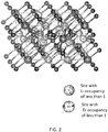
- FIG. 2 is a schematic diagram showing the crystal structure of the LEC structure. It is presumed that anion arrangement in the crystal structure is hexagonal close-packed ion arrangement.
- the solid electrolyte material in the first embodiment exhibits high Li ion conductivity and can realize a high-performance battery.
- cation arrangement of the solid electrolyte material in the first embodiment does not have to be the same as cation arrangement of the LEC structure.
- at least a part of Y and at least a part of Li may be irregularly arranged.
- a part of at least one kind of cation selected from the group consisting of a Li cation and a Y cation and the vacancy may be exchanged with each other.
- the solid electrolyte material in the first embodiment may include a first crystal phase and a different crystal phase having a crystal structure different from that of the first crystal layer.
- the different crystal phase may be interposed between portions of the first crystal phase, and the solid electrolyte material in the first embodiment may include an amorphous phase.
- the amorphous phase may be interposed between particles of the solid electrolyte described in the present embodiment.
- peaks may be present within all the ranges of diffraction angles 2 ⁇ of 15.4° to 15.8°, 28.6° to 29.5°, 30.6° to 31.1°, 32.9° to 33.5°, 39.9° to 40.6°, and 47.5° to 48.5°.
- the solid electrolyte material in the first embodiment may include Li, Y, Br, Cl, and I.
- peaks may be present within all the ranges of the diffraction angles 2 ⁇ of 15.1° to 15.7°, 27.3° to 29.4°, 30.1° to 31.1°, 32.0° to 33.7°, 39.0° to 40.5°, and 47.0° to 48.4°.
- the solid electrolyte material in the first embodiment may have a crystal structure.
- the arrangement of the anions in the crystal structure may have a hexagonal close-packed structure.
- the solid electrolyte material in the first embodiment may have a crystal structure represented by a space group P3/m1.
- a shape of the solid electrolyte material in the first embodiment is not particularly limited, and may be, for example, an acicular shape, a spherical shape, or an elliptical shape.
- the solid electrolyte material in the first embodiment may be particles.
- the solid electrolyte material in the first embodiment may be formed into a pellet shape or a plate shape by pressurized particles.
- the solid electrolyte material in the first embodiment may include a crystal phase or may include an amorphous phase.
- the median diameter thereof may be not less than 0.1 ⁇ m and not more than 100 ⁇ m.
- the median diameter may be not less than 0.5 ⁇ m and not more than 10 ⁇ m.
- the ion conductivity can be further improved.
- a better dispersion state of the solid electrolyte material in the first embodiment and an active material can be formed.
- the solid electrolyte material may have a smaller median diameter than the active material.
- a range in which a predetermined value A is a value B to a value C means "a range in which B ⁇ A ⁇ C”.
- the solid electrolyte material having the crystal structure in the first embodiment may be manufactured by the following method, for example.
- Binary halide raw material powders are prepared so as to provide a blending ratio of a target composition.
- the raw materials are not particularly limited.
- YBr 3 may be used in addition to the above-described raw materials.
- the composition of an anion can be determined by selecting the kinds of the raw material powders. After mixing the raw material powders well, the raw material powders are mixed and ground using a method such as mechanochemical milling to react. Alternatively, the raw material powders may be mixed well and then sintered in a vacuum or in an inert atmosphere such as an argon / nitrogen atmosphere.
- the structure of the crystal phase in the solid material (namely, the crystal structure) and the position of each peak in the X-ray diffraction pattern using the Cu-Ka as a radiation source can be determined by adjusting a raw material ratio and by adjusting a reaction method and a reaction condition of the raw material powders.
- the battery in the second embodiment is configured using the solid electrolyte material described in the first embodiment.
- the battery in the second embodiment comprises a positive electrode, a negative electrode, and an electrolyte layer.
- the electrolyte layer is a layer provided between the positive electrode and the negative electrode.
- At least one of the positive electrode, the electrolyte layer, and the negative electrode includes the solid electrolyte material in the first embodiment.
- the charge / discharge characteristic of the battery can be improved.
- FIG. 3 is a cross-sectional view showing a schematic configuration of a battery 1000 in the second embodiment.
- the battery 1000 in the second embodiment comprises a positive electrode 201, a negative electrode 203, and an electrolyte layer 202.
- the positive electrode 201 includes positive electrode active material particles 204 and solid electrolyte particles 100.
- the electrolyte layer 202 is disposed between the positive electrode 201 and the negative electrode 203.
- the electrolyte layer 202 includes an electrolyte material (for example, a solid electrolyte material).
- the negative electrode 203 includes negative electrode active material particles 205 and the solid electrolyte particles 100.
- the solid electrolyte particles 100 are particles each formed of the solid electrolyte material in the first embodiment or particles each including the solid electrolyte material in the first embodiment as a main component.
- the positive electrode 201 includes a material having a characteristic of storing and releasing metal ions (for example, lithium ions).
- the positive electrode 201 includes, for example, a positive electrode active material (for example, the positive electrode active material particles 204).
- the positive electrode active material examples include Li-containing transition metal oxides (e.g., Li(NiCoAl)O 2 or LiCoO 2 ), transition metal fluorides, polyanion materials, fluorinated polyanion materials, transition metal sulfides, transition metal oxyfluorides, transition metal oxysulfides, and transition metal oxynitrides.
- Li-containing transition metal oxides e.g., Li(NiCoAl)O 2 or LiCoO 2
- transition metal fluorides e.g., Li(NiCoAl)O 2 or LiCoO 2
- transition metal fluorides e.g., Li(NiCoAl)O 2 or LiCoO 2
- polyanion materials e.g., Li(NiCoAl)O 2 or LiCoO 2
- transition metal fluorides e.g., Li(NiCoAl)O 2 or LiCoO 2
- polyanion materials e.g., Li(NiCoAl)O
- the median diameter of the positive electrode active material particles 204 may be not less than 0.1 ⁇ m and not more than 100 ⁇ m. If the median diameter of the positive electrode active material particles 204 is not less than 0.1 ⁇ m, the positive electrode active material particles 204 and the halide solid electrolyte material can form a good dispersion state in the positive electrode. As a result, the charge / discharge characteristic of the battery is improved. In addition, if the median diameter of the positive electrode active material particles 204 is not more than 100 ⁇ m, Li diffusion in the positive electrode active material particles 204 is accelerated. As a result, the battery can operate at a high output.
- the surface of the positive electrode active material may be coated with an oxide which is different from the positive electrode active material in order to perform a battery operation.
- a typical coating material LiNbO 3 can be used.
- the surface coating material is not limited to LiNbO 3 , and the coating method is not limited, either.
- the thickness of the coating material is desirably approximately 1 to 50 nm to realize a high-performance battery.
- the median diameter of the positive electrode active material particles 204 may be larger than the median diameter of the halide solid electrolyte material. Thereby, the good dispersion state of the positive electrode active material particles 204 and the halide solid electrolyte material can be formed.
- the thickness of the positive electrode 201 may be not less than 10 ⁇ m and not more than 500 ⁇ m. If the thickness of the positive electrode is not less than 10 ⁇ m, a sufficient battery energy density can be ensured. If the thickness of the positive electrode is not more than 500 ⁇ m, an operation at a high output can be realized.
- the electrolyte layer 202 is a layer including an electrolyte material.
- the electrolyte material is, for example, a solid electrolyte material.
- the electrolyte layer 202 may be a solid electrolyte layer.
- the solid electrolyte layer may include the solid electrolyte material in the first embodiment as a main component.
- the solid electrolyte layer may include the solid electrolyte material in the above-described first embodiment, for example, at a weight ratio of not less than 50% (namely, not less than 50% by weight) with respect to the entire solid electrolyte layer.
- the charge / discharge characteristic of the battery can be further improved.
- the solid electrolyte layer may include, for example, the solid electrolyte material in the first embodiment described above at a weight ratio of not less than 70% (namely, not less than 70% by weight) with respect to the entire solid electrolyte layer.
- the charge / discharge characteristic of the battery can be further improved.
- the solid electrolyte layer includes the solid electrolyte material in the above-described first embodiment as a main component, and may further include inevitable impurities, starting materials used when the solid electrolyte material is synthesized, byproducts, or decomposition products.
- the solid electrolyte layer may include the solid electrolyte material in the first embodiment, for example, at a weight ratio of 100% (namely, 100% by weight) with respect to the entire solid electrolyte layer, excluding impurities mixed inevitably.
- the charge / discharge characteristic of the battery can be further improved.
- the solid electrolyte layer may be composed only of the solid electrolyte material in the first embodiment.
- the solid electrolyte layer may be composed of only a solid electrolyte material different from the solid electrolyte material in the first embodiment.
- the solid electrolyte material different from the solid electrolyte material in the first embodiment for example, Li 2 MgX 4 , Li 2 FeX 4 , Li(Al, Ga, In)X 4 , Li 3 (Al, Ga, In)X 6 , or Lil may be used.
- X includes at least one selected from the group consisting of Cl, Br, and I.
- the solid electrolyte layer may include simultaneously the solid electrolyte material in the first embodiment and the solid electrolyte material different from the solid electrolyte material in the first embodiment. At this time, both may be dispersed uniformly.
- a layer formed of the solid electrolyte material in the first embodiment and a layer formed of the solid electrolyte material different from the solid electrolyte material in the first embodiment may be sequentially arranged in the stacking direction of the battery.
- the thickness of the solid electrolyte layer may be not less than 1 ⁇ m and not more than 100 ⁇ m. If the thickness of the solid electrolyte layer is not less than 1 ⁇ m, the positive electrode 201 and the negative electrode 203 are easily separated. In addition, if the thickness of the solid electrolyte layer is not more than 100 ⁇ m, an operation with high output can be realized.
- the negative electrode 203 includes a material having a characteristic of storing and releasing metal ions (for example, Li ions).
- the negative electrode 203 includes, for example, a negative electrode active material (for example, the negative electrode active material particles 205).
- a metal material As the negative electrode active material, a metal material, a carbon material, an oxide, a nitride, a tin compound, or a silicon compound can be used.
- the metal material may be a single metal. Alternatively, the metal material may be an alloy. Examples of the metal material include lithium metal and a lithium alloy.
- Examples of the carbon material include natural graphite, coke, graphitized carbon, carbon fiber, spherical carbon, artificial graphite, and amorphous carbon. From the viewpoint of capacity density, silicon (Si), tin (Sn), a silicon compound, or a tin compound can be used. If a negative electrode active material having a low average reaction voltage is used, the effect of suppressing electrolysis by the solid electrolyte material in the first embodiment is better exhibited.
- the median diameter of the negative electrode active material particles 205 may be not less than 0.1 ⁇ m and not more than 100 ⁇ m. If the median diameter of the negative electrode active material particles 205 is not less than 0.1 ⁇ m, the negative electrode active material particles 205 and the solid electrolyte particles 100 can form a good dispersion state in the negative electrode. As a result, the charge / discharge characteristic of the battery is improved. In addition, if the median diameter of the negative electrode active material particles 205 is not more than 100 ⁇ m, the lithium diffusion in the negative electrode active material particles 205 is accelerated. As a result, the battery can operate at a high output.
- the median diameter of the negative electrode active material particles 205 may be larger than the median diameter of the solid electrolyte particles 100. As a result, the good dispersion state of the negative electrode active material particles 205 and the halide solid electrolyte material can be formed.
- the thickness of the negative electrode 203 may be not less than 10 ⁇ m and not more than 500 ⁇ m. If the thickness of the negative electrode is not less than 10 ⁇ m, the sufficient battery energy density can be secured. In addition, if the thickness of the negative electrode is not more than 500 ⁇ m, an operation with high output can be realized.
- At least one of the positive electrode 201, the electrolyte layer 202, and the negative electrode 203 may include a sulfide solid electrolyte or an oxide solid electrolyte for the purpose of improving ion conductivity.
- a sulfide solid electrolyte Li 2 S-P 2 S 5 , Li2S-SiS2, Li 2 S-B 2 S 3 , Li2S-GeS2, or Li 3.25 Ge 0.25 P 0.75 S 4 , or Li 10 GeP 2 S 12 can be used.
- a NASICON solid electrolyte such as LiTi 2 (PO 4 ) 3 and its element substitution products, a (LaLi)TiO 3 perovskite solid electrolyte, a LISICON solid electrolyte such as Li 14 ZnGe 4 O 16 , Li 4 SiO 4 , or LiGeO 4 and its element substitution products, a garnet solid electrolyte such as Li 7 La 3 Zr 2 O 12 and its element substitution products, Li 3 N and its H substitution products, or Li 3 PO 4 and its N substitution products can be used.
- At least one of the positive electrode 201, the electrolyte layer 202, and the negative electrode 203 may include an organic polymer solid electrolyte for the purpose of increasing ion conductivity.
- an organic polymer solid electrolyte for example, a compound of a polymer compound and a lithium salt can be used.
- the polymer compound may have an ethylene oxide structure. Since the polymer compound has the ethylene oxide structure, a large amount of lithium salt can be included, and the ion conductivity can be further increased.
- LiPF 6 , LiBF 4 , LiSbF 6 , LiAsF 6 , LiSO 3 CF 3 , LiN(SO 2 CF 3 ) 2 , LiN(SO 2 C 2 F 5 ) 2 , LiN(SO 2 CF 3 )(SO 2 C 4 F 9 ), or LiC(SO 2 CF 3 ) 3 can be used.
- the lithium salt one lithium salt selected from these may be used alone. Alternatively, a mixture of two or more lithium salts selected from these may be used as the lithium salt.
- At least one of the positive electrode 201, the electrolyte layer 202, and the negative electrode 203 may include a non-aqueous electrolyte solution, a gel electrolyte, and an ionic liquid for the purpose of facilitating exchange of lithium ions and improving the output characteristic of the battery.
- the non-aqueous electrolyte solution includes a non-aqueous solvent and a lithium salt dissolved in the non-aqueous solvent.
- a non-aqueous solvent a cyclic carbonate solvent, a chain carbonate solvent, a cyclic ether solvent, a chain ether solvent, a cyclic ester solvent, a chain ester solvent, or a fluorine solvent can be used.
- the cyclic carbonate solvent include ethylene carbonate, propylene carbonate, and butylene carbonate.
- Examples of the chain carbonate solvent include dimethyl carbonate, ethyl methyl carbonate, and diethyl carbonate.
- Examples of the cyclic ether solvent include tetrahydrofuran, 1,4-dioxane, and 1,3-dioxolane.
- Examples of the chain ether solvent include 1,2-dimethoxyethane and 1,2-diethoxyethane.
- Examples of the cyclic ester solvent include ⁇ -butyrolactone.
- Examples of the chain ester solvent include methyl acetate.
- Examples of the fluorine solvent include fluoroethylene carbonate, methyl fluoropropionate, fluorobenzene, fluoroethyl methyl carbonate, or fluorodimethylene carbonate.
- the non-aqueous solvent one non-aqueous solvent selected from these can be used alone.
- the non-aqueous electrolyte solution may include at least one fluorine solvent selected from the group consisting of fluoroethylene carbonate, methyl fluoropropionate, fluorobenzene, fluoroethyl methyl carbonate, and fluorodimethylene carbonate.
- LiPF 6 , LiBF 4 , LiSbF 6 , LiAsF 6 , LiSO 3 CF 3 , LiN(SO 2 CF 3 ) 2 , LiN(SO 2 C 2 F 5 ) 2 , LiN(SO 2 CF 3 )(SO 2 C 4 F 9 ), or LiC(SO 2 CF 3 ) 3 can be used.
- the lithium salt one lithium salt selected from these may be used alone. Alternatively, a mixture of two or more lithium salts selected from these may be used as the lithium salt.
- the concentration of the lithium salt is, for example, in the range of 0.5 to 2 mol/liter.
- a polymer material including a non-aqueous electrolyte solution can be used.
- the polymer material polyethylene oxide, polyacrylonitrile, polyvinylidene fluoride, polymethyl methacrylate, or a polymer having an ethylene oxide bond may be used.
- the cation which forms the ionic liquid may be an aliphatic chain quaternary salt such as tetraalkylammonium or tetraalkylphosphonium, an aliphatic cyclic ammonium such as pyrrolidinium, morpholinium, imidazolinium, tetrahydropyrimidinium, piperazinium or piperidinium, or a nitrogen-including heterocyclic aromatic cation such as pyridinium or imidazolium.
- an aliphatic chain quaternary salt such as tetraalkylammonium or tetraalkylphosphonium
- an aliphatic cyclic ammonium such as pyrrolidinium, morpholinium, imidazolinium, tetrahydropyrimidinium, piperazinium or piperidinium
- a nitrogen-including heterocyclic aromatic cation such as pyridinium or imidazolium.
- the anion which forms the ionic liquid may be PF 6 - , BF 4 - , SbF 6 - , AsF 6 - , SO 3 CF 3 - , N(SO 2 CF 3 ) 2 - , N(SO 2 C 2 F 5 ) 2 - , N(SO 2 CF 3 )(SO 2 C 4 F 9 ) - , or C(SO 2 CF 3 ) 3 - .
- the ionic liquid may include a lithium salt.
- At least one of the positive electrode 201, the electrolyte layer 202, and the negative electrode 203 may include a binder for the purpose of improving adhesion between the particles.
- the binder is used to improve the binding property of the material which forms the electrode.
- the binders include polyvinylidene fluoride, polytetrafluoroethylene, polyethylene, polypropylene, aramid resin, polyamide, polyimide, polyamideimide, polyacrylonitrile, polyacrylic acid, methyl polyacrylate ester, ethyl polyacrylate eter, hexyl polyacrylate ester, polymethacrylic acid, methyl polymethacrylate ester, ethyl polymethacrylate ester, hexyl polymethacrylate ester, polyvinyl acetate, polyvinylpyrrolidone, polyether, polyethersulfone, hexafluoropolypropylene, styrene butadiene rubber, or carb
- the binder may be a copolymer of two or more materials selected from the group consisting of tetrafluoroethylene, hexafluoroethylene, hexafluoropropylene, perfluoroalkyl vinyl ether, vinylidene fluoride, chlorotrifluoroethylene, ethylene, propylene, pentafluoropropylene, fluoromethyl vinyl ether, acrylic acid, and hexadiene.
- two or more kinds selected from these may be mixed and used as the binder.
- At least one of the positive electrode 201 and the negative electrode 203 may include a conductive assistant agent as necessary.
- the conductive assistant agent is used to lower electrode resistance.
- the conductive assistant agent include graphite such as natural graphite or artificial graphite, carbon black such as acetylene black or ketjen black, a conductive fiber such as a carbon fiber or a metal fiber, carbon fluoride, a metal powder such as aluminum, a conductive whisker such as zinc oxide or potassium titanate, a conductive metal oxide such as titanium oxide, or a conductive polymer compound such as polyaniline, polypyrrole, or polythiophene.
- cost reduction can be achieved by using a carbon conductive assistant agent as the conductive assistant agent.
- the battery in the second embodiment can be configured as a battery having various shapes such as a coin shape, a cylindrical shape, a prism shape, a sheet shape, a button shape, a flat shape, or a laminated shape.
- Li 3 YBr 6-x Cl x powders which were the solid electrolyte materials of the inventive example 1, were provided.
- the synthesized solid electrolyte materials were evaluated using an X-ray diffraction (XRD) method in an environment where the synthesized solid electrolyte material was maintained in a dry atmosphere with a dew point value of -40°C or lower.
- XRD X-ray diffraction
- Cu-Ka rays were used for the X-ray source.
- the X-ray diffraction was measured by a ⁇ -2 ⁇ method using Cu-Ka rays (wavelengths 1.5405 ⁇ (i.e., 0.15405 nm) and 1.5444 ⁇ (i.e., 0.15444 nm)) as X-rays.
- XRD X-ray diffraction
- Table 1 shows positions of a plurality of peaks (namely, XRD peak angles) within the range where the value of 2 ⁇ of the XRD peak patterns of the inventive examples 1-1 to 1-3 is 10° to 50°.
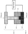
- FIG. 4 is a schematic diagram showing an evaluation method of ion conductivity.
- a pressure-molding die 300 includes a frame 301 formed of an electronically insulating polycarbonate, an upper punch part 303 and a lower punch part 302, both of which are formed of electron conductive stainless steel.
- the ion conductivity was evaluated by the following method.
- the inside of the pressure-molding die 300 was filled with the powder of the solid electrolyte material of the inventive example 1 (example of the solid electrolyte particles 100).
- the powder was pressurized uniaxially at 400 MPa to produce a conductivity measurement cell of the inventive example 1.
- lead wires were routed from the upper punch part 303 and the lower punch part 302, connected to a potentiostat (Princeton Applied Research, VersaSTAT4) equipped with a frequency response analyzer.
- the ion conductivity at room temperature was measured by an electrochemical impedance measurement method.
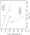
- FIG. 7 is a graph showing temperature dependence of the ion conductivity of the solid electrolyte.
- FIG. 7 shows the measurement results of the inventive example 1-2. The results shown in FIG. 7 were measured by the following method. Similar measurements were also conducted in the other inventive examples 1-1 and 1-3. As a result, within the temperature range from -30°C to 80°C, in all the inventive examples 1-1 to 1-3, no sudden change in conductivity indicating a phase change (i.e., a phase transition) was observed.
- the solid electrolyte materials of the inventive examples 1-1 to 1-3 which corresponded to a thickness of 700 ⁇ m were inserted into respective insulating outer cylinders. Each of the solid electrolyte materials was pressure-molded at a pressure of 40 MPa to provide solid electrolyte layers. Next, aluminum electrodes each corresponding to a thickness of 50 ⁇ m was stacked on the upper and lower surfaces of each of the solid electrolyte layers. Each of the solid electrolyte layers having the aluminum electrodes was press-molded at a pressure of 360 MPa to produce stacking structures.
- test bodies each including the material of the inventive example provided by the above method were put in a thermostatic chamber, and the temperature dependence of the ion conductivity was measured in a temperature rising process and a temperature falling process.
- the solid electrolyte materials of the inventive example 1 were evaluated for the compositions thereof using ICP (Inductively Coupled Plasma) emission spectroscopy. As a result, in each of the inventive examples 1-1 to 1-3, deviation of Li /Yfrom its charged composition was within 3%. As a result, it can be said that the charged composition with the planetary ball mill was almost the same as the composition of the solid electrolyte material described in each of the inventive examples.
- ICP Inductively Coupled Plasma
- Table 1 shows the XRD peak angle and the conductivity at 22°C.
- Li 3 InBr 6 which was the solid electrolyte material of the comparative example 1-2, was provided.
- the ion conductivity and the phase transition of the solid electrolyte material of the comparative example 1-2 were evaluated.
- the ion conductivity measured at 22°C was less than 1 ⁇ 10 -7 S/cm.
- the temperature dependence of the ion conductivity of the solid electrolyte material of the comparative example 1-2 is shown in FIG. 7 .
- FIG. 7 due to the temperature dependence of the conductivity, the conductivity changed suddenly at around 55°C during the temperature rising process. In other words, a phase change was observed in the solid electrolyte material of the comparative example 1-2.
- Li 2 FeCl 4 which was the solid electrolyte material of the comparative example 1-3, was provided.
- the ion conductivity of the solid electrolyte material of the comparative example 1-3 was evaluated in the same manner as in the inventive example 1.
- the ion conductivity measured at 22°C was 8.7 ⁇ 10 -6 S/cm.
- the solid electrolyte material Li 3 YBr 6-x Cl x of the inventive example 1 and LiCoO 2 which was the positive electrode active material, were prepared at a volume ratio of 30:70. These were mixed in an agate mortar to prepare a positive electrode mixture.
- the solid electrolyte materials of the inventive example 1 each of which corresponded to a thickness of 700 ⁇ m, and 12.3 mg of the positive electrode mixture were stacked in this order in respective insulating outer cylinders.
- Each of the solid electrolyte materials having the positive electrode mixture was pressure-molded at a pressure of 360 MPa to provide a positive electrode and a solid electrolyte layer.
- a metal In (thickness: 200 ⁇ m) was stacked on the opposite side to the side which was in contact with the positive electrode of the solid electrolyte layer.
- Each of the solid electrolyte layer having the positive electrode and the metal In was pressure-molded at a pressure of 80 MPa to produce a stacking structure of the positive electrode, the solid electrolyte layer, and the negative electrode.
- stainless-steel current collectors were disposed on the upper and lower parts of each of the stacking structures, and current collector leads were attached to the current collectors.
- an insulating ferrule was used to block and seal the insides of the insulating outer cylinders from the outside atmosphere.
- FIG. 8 shows a graph of the inventive example 1-2 as a typical initial discharge characteristic.
- the results shown in FIG. 8 were measured by the following method.
- the secondary batteries of the inventive examples 1 were disposed in a thermostatic chamber at 25°C. Constant-current charge was performed at a current value of 0.05 C rate (20 hour rate) with respect to theoretical capacity of each of the batteries, and the charge was terminated at a voltage of 3.6 V.
- each of the batteries was discharged at a current value of the same 0.05 C rate as the above, and the discharge was terminated at a voltage of 1.9 V.
- the initial discharge capacities are shown in Table 1.
- each of the solid electrolytes of the inventive examples 1 has a stable structure in the assumed operation temperature range of the battery.
- each of the batteries of the inventive examples 1-1 to 1-3 exhibited a charge / discharge operation at room temperature.
- the discharge capacity was hardly provided, and the battery operation failed to be observed.
- the solid electrolyte material according to the present disclosure is an electrolyte material that does not generate hydrogen sulfide and can stably maintain high lithium ion conductivity. Further, it is shown that an all-solid battery which does not generate hydrogen sulfide and is excellent in the charge / discharge characteristic can be realized.
- the solid electrolyte materials synthesized in the inventive examples 1-1 to 1-3 were annealed, respectively, at 300°C for 48 hours in an electric furnace put in a glove box maintained in a dry and low-oxygen atmosphere with a dew point of -90°C or less and an oxygen value of 5 ppm or less.
- the solid electrolyte materials synthesized in the inventive example 2 were evaluated by an X-ray diffraction method (XRD) in an environment where a dry atmosphere with a dew point value of -40°C or lower was maintained.
- XRD X-ray diffraction method
- Cu-Ka ray was used as the X-ray source.
- the X-ray diffraction was measured by the ⁇ -2 ⁇ method using the Cu-Ka rays (wavelengths of 1.5405 ⁇ (i.e., 0.15405 nm) and 1.5444 ⁇ (i.e., 0.15444 nm)) as the X-rays.
- 1.5405 ⁇ i.e., 0.15405 nm
- 1.5444 ⁇ i.e., 0.15444 nm
- FIG. 6 shows the peak pattern of the inventive example 2-2, namely, the peak pattern of Li 3 YBrCl 5 .
- the peaks observed in the inventive example 2-2 were sharper, and peaks that were not observed in the inventive example 1-2 were observed. This would be an effect of homogenization of the crystal structure due to the progress of crystallization by the annealing. In addition, little change in the positions of the peaks due to the annealing was observed.
- the secondary batteries were manufactured using the solid electrolyte materials of the inventive examples 2-1 to 2-3 in the same manner as in the inventive example 1.
- the results of the initial discharge capacity are shown in Table 2.
- each of the batteries using the solid electrolyte materials described in the present example each of the batteries exhibited an initial discharge capacity of a battery of 120 ⁇ Ah at room temperature, similarly to the case in the inventive example 1.
- the solid electrolyte materials of the inventive examples 2-1 to 2-3 exhibit high ion conductivity of not less than 1 ⁇ 10 -4 S/cm.
- the solid electrolyte material according to the present disclosure is an electrolyte material that does not generate hydrogen sulfide and can stably maintain high lithium ion conductivity. Further, it is shown that an all-solid battery which does not generate hydrogen sulfide and is excellent in the charge / discharge characteristic can be realized.
- the synthesized solid electrolyte materials were evaluated by an X-ray diffraction method (XRD) in an environment where a dry atmosphere with a dew point value of -40°C or lower was maintained.
- X-ray source Cu-Ka ray was used.
- the X-ray diffraction was measured by the ⁇ -2 ⁇ method using the Cu-Ka rays (wavelengths of 1.5405 ⁇ (i.e., 0.15405 nm) and 1.5444 ⁇ (i.e., 0.15444 nm)) as the X-rays.
- Table 3 shows the XRD peak angles provided in all the inventive examples 3-1 and 3-2.
- the ion conductivity was evaluated by the following method.
- the inside of the pressure-molding die 300 was filled with the powder of the solid electrolyte material of the inventive example 3 (example of the solid electrolyte particles 100).
- the powder was pressurized uniaxially at 400 MPa to produce a conductivity measurement cell of the inventive example 3.
- the solid electrolyte materials of the inventive examples 3-1 to 3-2 which corresponded to a thickness of 700 ⁇ m were inserted into respective insulating outer cylinders. Each of the solid electrolyte materials was pressure-molded at a pressure of 40 MPa to provide solid electrolyte layers. Next, aluminum powder which corresponded to a thickness of 50 ⁇ m was stacked on the upper and lower surfaces of each of the solid electrolyte layers. Each of the solid electrolyte layers having the aluminum powders was press-molded at a pressure of 360 MPa to produce stacking structures.
- test bodies each including the stacking structure provided by the above method were put in a thermostatic chamber, and the temperature dependence of the ion conductivity was measured in a temperature rising process and a temperature falling process.
- the solid electrolyte materials of the inventive example 3 were evaluated for the compositions thereof using the ICP (Inductively Coupled Plasma) emission spectroscopy.
- ICP Inductively Coupled Plasma
- the deviation of Li / Y from its charged composition was within 3%.
- the charged composition with the planetary ball mill was almost the same as the composition of the solid electrolyte material described in each of the inventive examples.
- the dried and solidified powder was put in an alumina crucible and taken out in an air atmosphere.
- the powder after the heat treatment was reground in an agate mortar to provide a positive electrode active material of the inventive example 3 in which a coating layer was formed on the particle surface layer.
- a coating layer was formed on at least a part of the particle surface of all or some of the plurality of the particles.
- the material of the coating layer is LiNbO 3 .
- the solid electrolyte material Li 3 YCl l Br m I n of the inventive example 3 and Li(NiCoAl)O 2 which was the positive electrode active material having particle surface coated with LiNbO 3 , were prepared at a volume ratio of 30:70. These were mixed in an agate mortar to produce a positive electrode mixture.
- the solid electrolyte materials of the inventive example 3 each of which corresponded to a thickness of 700 ⁇ m, and 12.3 mg of the positive electrode mixture were stacked in this order in respective insulating outer cylinder.
- Each of the solid electrolyte materials having the positive electrode mixture was pressure-molded at a pressure of 360 MPa to provide a positive electrode and a solid electrolyte layer.
- a metal In (thickness: 200 ⁇ m) was stacked on the opposite side to the side which was in contact with the positive electrode of the solid electrolyte layer.
- Each of the solid electrolyte layer having the positive electrode and the metal In were pressure-molded at a pressure of 80 MPa to produce a stacking structure of the positive electrode, the solid electrolyte layer, and the negative electrode.
- the secondary batteries of the inventive examples 3 were disposed in a thermostatic chamber at 25°C. Constant-current charge was performed at a current value of 0.05 C rate (20 hour rate) with respect to theoretical capacity of each of the batteries, and the charge was terminated at a voltage of 3.7 V. Next, each of the batteries was discharged at a current value of the same 0.05 C rate as the above, and the discharge was terminated at a voltage of 1.9 V. Using the above method, the same measurement was performed in all of the inventive examples 3-1 to 3-2. In each of the inventive examples 3-1 and 3-2, a good discharge amount which was the same as that in the inventive example 1 was provided.
- the solid electrolyte material according to the present disclosure is an electrolyte material that does not generate hydrogen sulfide and can stably maintain high lithium ion conductivity. Further, it is shown that an all-solid battery which does not generate hydrogen sulfide and is excellent in the charge / discharge characteristic can be realized.
- the battery of the present disclosure can be used as, for example, an all-solid lithium secondary battery.
Landscapes
- Chemical & Material Sciences (AREA)
- Engineering & Computer Science (AREA)
- Organic Chemistry (AREA)
- Manufacturing & Machinery (AREA)
- Chemical Kinetics & Catalysis (AREA)
- Electrochemistry (AREA)
- General Chemical & Material Sciences (AREA)
- Inorganic Chemistry (AREA)
- Geology (AREA)
- Life Sciences & Earth Sciences (AREA)
- Physics & Mathematics (AREA)
- Condensed Matter Physics & Semiconductors (AREA)
- General Physics & Mathematics (AREA)
- Materials Engineering (AREA)
- Secondary Cells (AREA)
- Conductive Materials (AREA)
- Battery Electrode And Active Subsutance (AREA)
- Compounds Of Alkaline-Earth Elements, Aluminum Or Rare-Earth Metals (AREA)
Abstract
Description
- The present disclosure relates to a solid electrolyte material and a battery.
-
-
Patent Literature 1 discloses an all-solid battery using a sulfide solid electrolyte. - Patent Literature 2 discloses an all-solid battery using a halide including indium as a solid electrolyte.
- Non-Patent Literature 1 discloses Li3YCl6.
-
- Patent Literature 1: Japanese Patent Application Publication No.
2011-129312 - Patent Literature 2: Japanese Patent Application Publication No.
2006-244734 - Non-patent Literature 1: Z. anorg. allg. Chem.623 (1997), 1067.
- In the prior art, realization of a solid electrolyte material having high lithium ion conductivity is desired.
- The solid electrolyte material in one aspect of the present disclosure comprises Li, Y, Br, and Cl wherein in an X-ray diffraction pattern in which Cu-Ka is used as a radiation source, peaks are present within all ranges of diffraction angles 2θ of 15.1° to 15.8°, 27.3° to 29.5°, 30.1° to 31.1°, 32.0° to 33.7°, 39.0° to 40.6°, and 47.0° to 48.5°.
- According to the present disclosure, a solid electrolyte material having high lithium ion conductivity can be realized.
-
-
FIG. 1 is a schematic diagram showing a crystal structure of LiCl. -
FIG. 2 is a schematic diagram showing a crystal structure of Li3ErCl6. -
FIG. 3 is a cross-sectional view showing a schematic configuration of a battery in a second embodiment. -
FIG. 4 is a schematic view showing an evaluation method of ion conductivity. -
FIG. 5 is a diagram showing a peak pattern in an XRD of Li3YBrCl5. -
FIG. 6 is a diagram showing a peak pattern in the XRD of Li3YBrCl5 which has been subjected to annealing. -
FIG. 7 is a graph showing temperature dependence of the ion conductivity of a solid electrolyte. -
FIG. 8 is a graph showing an initial discharge characteristic. - Hereinafter, embodiments of the present disclosure will be described with reference to the drawings.
- The solid electrolyte material in the first embodiment is a solid electrolyte material comprising Li, Y, Br, and Cl wherein in an X-ray diffraction pattern in which Cu-Kα is used as a radiation source, peaks are present within all ranges of diffraction angles 2θ of 15.1° to 15.8°, 27.3° to 29.5°, 30.1° to 31.1°, 32.0° to 33.7°, 39.0° to 40.6°, and 47.0° to 48.5°.
- According to the above configuration, a halide solid electrolyte material having high lithium ion conductivity can be realized. In addition, a solid electrolyte material having a stable structure can be realized in the presumed operation temperature range of a battery (for example, within the range of -30°C to 80°C). In other words, the solid electrolyte material of the first embodiment does not have a configuration (for example, the configuration of Patent Literature 2) in which a phase transition temperature is present in the operation temperature range of the battery. Thereby, even in an environment where there is a temperature change, high ion conductivity can be stably maintained without causing the phase transition within the operation temperature range of the battery, and a more practical battery can be realized.
- In addition, according to the above configuration, an all-solid secondary battery excellent in the charging / discharging characteristic can be realized by using the solid electrolyte material of the first embodiment. In addition, by using the solid electrolyte material of the first embodiment, an all-solid secondary battery which does not include sulfur can be realized. In other words, the solid electrolyte material of the first embodiment does not have a configuration (for example, the configuration of Patent Literature 1) in which hydrogen sulfide is generated when exposed to the atmosphere. As a result, an all-solid secondary battery which does not generate hydrogen sulfide and is excellent in safety can be realized.
- The solid electrolyte material in the first embodiment has, as a fundamental structure (see
FIG.1 ), LiCl, which has a rock salt structure. In the solid electrolyte material in the first embodiment, a part of LiCl is replaced with Br, and a part of Li is replaced with a rare earth having a valence of +3. Non-Patent Literature 1 reports a similar crystal structure as Li3ErCl6 (hereinafter, referred to as LEC). Its detailed atomic arrangement is published in the Inorganic Crystal Structure Database (ICSD). -
FIG. 2 is a schematic diagram showing the crystal structure of the LEC structure. It is presumed that anion arrangement in the crystal structure is hexagonal close-packed ion arrangement. In addition, the space group in the LEC crystal structure is P3/m1, and the details of the lattice constants thereof are a = 11.169 Å (namely, 1.1169 nm) and c = 6.023 Å (namely, 0.6023 nm). The solid electrolyte material in the first embodiment exhibits high Li ion conductivity and can realize a high-performance battery. - In addition, cation arrangement of the solid electrolyte material in the first embodiment does not have to be the same as cation arrangement of the LEC structure. In other words, at least a part of Y and at least a part of Li may be irregularly arranged. In addition, if a vacancy of a cation site is present in the crystal, a part of at least one kind of cation selected from the group consisting of a Li cation and a Y cation and the vacancy may be exchanged with each other.
- The solid electrolyte material in the first embodiment may include a first crystal phase and a different crystal phase having a crystal structure different from that of the first crystal layer.
- In this case, the different crystal phase may be interposed between portions of the first crystal phase, and the solid electrolyte material in the first embodiment may include an amorphous phase. In this case, the amorphous phase may be interposed between particles of the solid electrolyte described in the present embodiment. According to the above configuration, a solid electrolyte material having higher lithium ion conductivity can be realized. Specifically, the conduction of lithium ions is promoted by the amorphous phase. As a result, the lithium ion conductivity is further improved.
- In the solid electrolyte material in the first embodiment, in an X-ray diffraction pattern using Cu-Kα as a radiation source, peaks may be present within all the ranges of diffraction angles 2θ of 15.4° to 15.8°, 28.6° to 29.5°, 30.6° to 31.1°, 32.9° to 33.5°, 39.9° to 40.6°, and 47.5° to 48.5°.
- According to the above configuration, a solid electrolyte material having higher lithium ion conductivity can be realized.
- The solid electrolyte material in the first embodiment may include Li, Y, Br, Cl, and I. In this case, in the X-ray diffraction pattern using the Cu-Kα as a radiation source, peaks may be present within all the ranges of the diffraction angles 2θ of 15.1° to 15.7°, 27.3° to 29.4°, 30.1° to 31.1°, 32.0° to 33.7°, 39.0° to 40.5°, and 47.0° to 48.4°.
- According to the above configuration, a solid electrolyte material having higher lithium ion conductivity can be realized.
- The solid electrolyte material in the first embodiment may have a crystal structure. In this case, the arrangement of the anions in the crystal structure may have a hexagonal close-packed structure.
- According to the above configuration, a solid electrolyte material having higher lithium ion conductivity can be realized.
- The solid electrolyte material in the first embodiment may have a crystal structure represented by a space group P3/m1.
- According to the above configuration, a solid electrolyte material having higher lithium ion conductivity can be realized.
- A shape of the solid electrolyte material in the first embodiment is not particularly limited, and may be, for example, an acicular shape, a spherical shape, or an elliptical shape. For example, the solid electrolyte material in the first embodiment may be particles. In addition, the solid electrolyte material in the first embodiment may be formed into a pellet shape or a plate shape by pressurized particles. In addition, the solid electrolyte material in the first embodiment may include a crystal phase or may include an amorphous phase.
- For example, if the shape of the solid electrolyte material in the first embodiment is particulate (for example, spherical), the median diameter thereof may be not less than 0.1 µm and not more than 100 µm. In addition, in the first embodiment, the median diameter may be not less than 0.5 µm and not more than 10 µm.
- According to the above configuration, the ion conductivity can be further improved. In addition, a better dispersion state of the solid electrolyte material in the first embodiment and an active material can be formed. In addition, in the first embodiment, the solid electrolyte material may have a smaller median diameter than the active material.
- According to the above configuration, a better dispersed state of the solid electrolyte material in the first embodiment and the active material can be formed.
- In the present disclosure, the recitation "a range in which a predetermined value A is a value B to a value C" means "a range in which B ≤ A ≤ C".
- The solid electrolyte material having the crystal structure in the first embodiment may be manufactured by the following method, for example.
- Binary halide raw material powders are prepared so as to provide a blending ratio of a target composition. For example, if Li3YBrCl5 is produced, LiBr, YCl3 and LiCl are prepared in a molar ratio of 1:1:2. The raw materials are not particularly limited. For example, YBr3 may be used in addition to the above-described raw materials. The composition of an anion can be determined by selecting the kinds of the raw material powders. After mixing the raw material powders well, the raw material powders are mixed and ground using a method such as mechanochemical milling to react. Alternatively, the raw material powders may be mixed well and then sintered in a vacuum or in an inert atmosphere such as an argon / nitrogen atmosphere.
- Thereby, the solid electrolyte material including the crystal phase as described above is provided.
- The structure of the crystal phase in the solid material (namely, the crystal structure) and the position of each peak in the X-ray diffraction pattern using the Cu-Ka as a radiation source can be determined by adjusting a raw material ratio and by adjusting a reaction method and a reaction condition of the raw material powders.
- Hereinafter, the second embodiment will be described. The description which has been set forth in the above-described first embodiment is omitted as appropriate.
- The battery in the second embodiment is configured using the solid electrolyte material described in the first embodiment.
- The battery in the second embodiment comprises a positive electrode, a negative electrode, and an electrolyte layer.
- The electrolyte layer is a layer provided between the positive electrode and the negative electrode.
- At least one of the positive electrode, the electrolyte layer, and the negative electrode includes the solid electrolyte material in the first embodiment.
- According to the above configuration, the charge / discharge characteristic of the battery can be improved.
- A specific example of the battery in the second embodiment will be described below.
-
FIG. 3 is a cross-sectional view showing a schematic configuration of abattery 1000 in the second embodiment. Thebattery 1000 in the second embodiment comprises apositive electrode 201, anegative electrode 203, and anelectrolyte layer 202. - The
positive electrode 201 includes positive electrodeactive material particles 204 andsolid electrolyte particles 100. - The
electrolyte layer 202 is disposed between thepositive electrode 201 and thenegative electrode 203. - The
electrolyte layer 202 includes an electrolyte material (for example, a solid electrolyte material). - The
negative electrode 203 includes negative electrodeactive material particles 205 and thesolid electrolyte particles 100. - The
solid electrolyte particles 100 are particles each formed of the solid electrolyte material in the first embodiment or particles each including the solid electrolyte material in the first embodiment as a main component. - The
positive electrode 201 includes a material having a characteristic of storing and releasing metal ions (for example, lithium ions). Thepositive electrode 201 includes, for example, a positive electrode active material (for example, the positive electrode active material particles 204). - Examples of the positive electrode active material include Li-containing transition metal oxides (e.g., Li(NiCoAl)O2 or LiCoO2), transition metal fluorides, polyanion materials, fluorinated polyanion materials, transition metal sulfides, transition metal oxyfluorides, transition metal oxysulfides, and transition metal oxynitrides.
- The median diameter of the positive electrode
active material particles 204 may be not less than 0.1 µm and not more than 100 µm. If the median diameter of the positive electrodeactive material particles 204 is not less than 0.1 µm, the positive electrodeactive material particles 204 and the halide solid electrolyte material can form a good dispersion state in the positive electrode. As a result, the charge / discharge characteristic of the battery is improved. In addition, if the median diameter of the positive electrodeactive material particles 204 is not more than 100 µm, Li diffusion in the positive electrodeactive material particles 204 is accelerated. As a result, the battery can operate at a high output. - The surface of the positive electrode active material may be coated with an oxide which is different from the positive electrode active material in order to perform a battery operation. As a typical coating material, LiNbO3 can be used. As long as the battery operation can be performed, the surface coating material is not limited to LiNbO3, and the coating method is not limited, either. Typically, the thickness of the coating material is desirably approximately 1 to 50 nm to realize a high-performance battery.
- The median diameter of the positive electrode
active material particles 204 may be larger than the median diameter of the halide solid electrolyte material. Thereby, the good dispersion state of the positive electrodeactive material particles 204 and the halide solid electrolyte material can be formed. - With regard to a volume ratio "v: 100-v" between the positive electrode
active material particles 204 and the halide solid electrolyte material included in thepositive electrode - The thickness of the
positive electrode 201 may be not less than 10 µm and not more than 500 µm. If the thickness of the positive electrode is not less than 10 µm, a sufficient battery energy density can be ensured. If the thickness of the positive electrode is not more than 500 µm, an operation at a high output can be realized. - The
electrolyte layer 202 is a layer including an electrolyte material. The electrolyte material is, for example, a solid electrolyte material. In other words, theelectrolyte layer 202 may be a solid electrolyte layer. - The solid electrolyte layer may include the solid electrolyte material in the first embodiment as a main component. In other words, the solid electrolyte layer may include the solid electrolyte material in the above-described first embodiment, for example, at a weight ratio of not less than 50% (namely, not less than 50% by weight) with respect to the entire solid electrolyte layer.
- According to the above configuration, the charge / discharge characteristic of the battery can be further improved.
- In addition, the solid electrolyte layer may include, for example, the solid electrolyte material in the first embodiment described above at a weight ratio of not less than 70% (namely, not less than 70% by weight) with respect to the entire solid electrolyte layer.
- According to the above configuration, the charge / discharge characteristic of the battery can be further improved.
- The solid electrolyte layer includes the solid electrolyte material in the above-described first embodiment as a main component, and may further include inevitable impurities, starting materials used when the solid electrolyte material is synthesized, byproducts, or decomposition products.
- In addition, the solid electrolyte layer may include the solid electrolyte material in the first embodiment, for example, at a weight ratio of 100% (namely, 100% by weight) with respect to the entire solid electrolyte layer, excluding impurities mixed inevitably.
- According to the above configuration, the charge / discharge characteristic of the battery can be further improved.
- As described above, the solid electrolyte layer may be composed only of the solid electrolyte material in the first embodiment.
- Alternatively, the solid electrolyte layer may be composed of only a solid electrolyte material different from the solid electrolyte material in the first embodiment. As the solid electrolyte material different from the solid electrolyte material in the first embodiment, for example, Li2MgX4, Li2FeX4, Li(Al, Ga, In)X4, Li3(Al, Ga, In)X6, or Lil may be used. Here, X includes at least one selected from the group consisting of Cl, Br, and I.
- The solid electrolyte layer may include simultaneously the solid electrolyte material in the first embodiment and the solid electrolyte material different from the solid electrolyte material in the first embodiment. At this time, both may be dispersed uniformly. Alternatively, a layer formed of the solid electrolyte material in the first embodiment and a layer formed of the solid electrolyte material different from the solid electrolyte material in the first embodiment may be sequentially arranged in the stacking direction of the battery.
- The thickness of the solid electrolyte layer may be not less than 1 µm and not more than 100 µm. If the thickness of the solid electrolyte layer is not less than 1 µm, the
positive electrode 201 and thenegative electrode 203 are easily separated. In addition, if the thickness of the solid electrolyte layer is not more than 100 µm, an operation with high output can be realized. - The
negative electrode 203 includes a material having a characteristic of storing and releasing metal ions (for example, Li ions). Thenegative electrode 203 includes, for example, a negative electrode active material (for example, the negative electrode active material particles 205). - As the negative electrode active material, a metal material, a carbon material, an oxide, a nitride, a tin compound, or a silicon compound can be used. The metal material may be a single metal. Alternatively, the metal material may be an alloy. Examples of the metal material include lithium metal and a lithium alloy. Examples of the carbon material include natural graphite, coke, graphitized carbon, carbon fiber, spherical carbon, artificial graphite, and amorphous carbon. From the viewpoint of capacity density, silicon (Si), tin (Sn), a silicon compound, or a tin compound can be used. If a negative electrode active material having a low average reaction voltage is used, the effect of suppressing electrolysis by the solid electrolyte material in the first embodiment is better exhibited.
- The median diameter of the negative electrode
active material particles 205 may be not less than 0.1 µm and not more than 100 µm. If the median diameter of the negative electrodeactive material particles 205 is not less than 0.1 µm, the negative electrodeactive material particles 205 and thesolid electrolyte particles 100 can form a good dispersion state in the negative electrode. As a result, the charge / discharge characteristic of the battery is improved. In addition, if the median diameter of the negative electrodeactive material particles 205 is not more than 100 µm, the lithium diffusion in the negative electrodeactive material particles 205 is accelerated. As a result, the battery can operate at a high output. - The median diameter of the negative electrode
active material particles 205 may be larger than the median diameter of thesolid electrolyte particles 100. As a result, the good dispersion state of the negative electrodeactive material particles 205 and the halide solid electrolyte material can be formed. - With regard to a volume ratio "v : 100-v" of the negative electrode
active material particles 205 and thesolid electrolyte particles 100 included in thenegative electrode - The thickness of the
negative electrode 203 may be not less than 10 µm and not more than 500 µm. If the thickness of the negative electrode is not less than 10 µm, the sufficient battery energy density can be secured. In addition, if the thickness of the negative electrode is not more than 500 µm, an operation with high output can be realized. - At least one of the
positive electrode 201, theelectrolyte layer 202, and thenegative electrode 203 may include a sulfide solid electrolyte or an oxide solid electrolyte for the purpose of improving ion conductivity. As the sulfide solid electrolyte, Li2S-P2S5, Li2S-SiS2, Li2S-B2S3, Li2S-GeS2, or Li3.25Ge0.25P0.75S4, or Li10GeP2S12 can be used. As the oxide solid electrolyte, a NASICON solid electrolyte such as LiTi2(PO4)3 and its element substitution products, a (LaLi)TiO3 perovskite solid electrolyte, a LISICON solid electrolyte such as Li14ZnGe4O16, Li4SiO4, or LiGeO4 and its element substitution products, a garnet solid electrolyte such as Li7La3Zr2O12 and its element substitution products, Li3N and its H substitution products, or Li3PO4 and its N substitution products can be used. - At least one of the
positive electrode 201, theelectrolyte layer 202, and thenegative electrode 203 may include an organic polymer solid electrolyte for the purpose of increasing ion conductivity. As the organic polymer solid electrolyte, for example, a compound of a polymer compound and a lithium salt can be used. The polymer compound may have an ethylene oxide structure. Since the polymer compound has the ethylene oxide structure, a large amount of lithium salt can be included, and the ion conductivity can be further increased. As the lithium salt, LiPF6, LiBF4, LiSbF6, LiAsF6, LiSO3CF3, LiN(SO2CF3)2, LiN(SO2C2F5)2, LiN(SO2CF3)(SO2C4F9), or LiC(SO2CF3)3 can be used. As the lithium salt, one lithium salt selected from these may be used alone. Alternatively, a mixture of two or more lithium salts selected from these may be used as the lithium salt. - At least one of the
positive electrode 201, theelectrolyte layer 202, and thenegative electrode 203 may include a non-aqueous electrolyte solution, a gel electrolyte, and an ionic liquid for the purpose of facilitating exchange of lithium ions and improving the output characteristic of the battery. - The non-aqueous electrolyte solution includes a non-aqueous solvent and a lithium salt dissolved in the non-aqueous solvent. As the non-aqueous solvent, a cyclic carbonate solvent, a chain carbonate solvent, a cyclic ether solvent, a chain ether solvent, a cyclic ester solvent, a chain ester solvent, or a fluorine solvent can be used. Examples of the cyclic carbonate solvent include ethylene carbonate, propylene carbonate, and butylene carbonate. Examples of the chain carbonate solvent include dimethyl carbonate, ethyl methyl carbonate, and diethyl carbonate. Examples of the cyclic ether solvent include tetrahydrofuran, 1,4-dioxane, and 1,3-dioxolane. Examples of the chain ether solvent include 1,2-dimethoxyethane and 1,2-diethoxyethane. Examples of the cyclic ester solvent include γ-butyrolactone. Examples of the chain ester solvent include methyl acetate. Examples of the fluorine solvent include fluoroethylene carbonate, methyl fluoropropionate, fluorobenzene, fluoroethyl methyl carbonate, or fluorodimethylene carbonate. As the non-aqueous solvent, one non-aqueous solvent selected from these can be used alone. Alternatively, a combination of two or more non-aqueous solvents selected from these can be used as the non-aqueous solvent. The non-aqueous electrolyte solution may include at least one fluorine solvent selected from the group consisting of fluoroethylene carbonate, methyl fluoropropionate, fluorobenzene, fluoroethyl methyl carbonate, and fluorodimethylene carbonate. As the lithium salt, LiPF6, LiBF4, LiSbF6, LiAsF6, LiSO3CF3, LiN(SO2CF3)2, LiN(SO2C2F5)2, LiN(SO2CF3)(SO2C4F9), or LiC(SO2CF3)3 can be used. As the lithium salt, one lithium salt selected from these may be used alone. Alternatively, a mixture of two or more lithium salts selected from these may be used as the lithium salt. The concentration of the lithium salt is, for example, in the range of 0.5 to 2 mol/liter.
- As the gel electrolyte, a polymer material including a non-aqueous electrolyte solution can be used. As the polymer material, polyethylene oxide, polyacrylonitrile, polyvinylidene fluoride, polymethyl methacrylate, or a polymer having an ethylene oxide bond may be used.
- The cation which forms the ionic liquid may be an aliphatic chain quaternary salt such as tetraalkylammonium or tetraalkylphosphonium, an aliphatic cyclic ammonium such as pyrrolidinium, morpholinium, imidazolinium, tetrahydropyrimidinium, piperazinium or piperidinium, or a nitrogen-including heterocyclic aromatic cation such as pyridinium or imidazolium. The anion which forms the ionic liquid may be PF6 -, BF4 -, SbF6 -, AsF6 -, SO3CF3 -, N(SO2CF3)2 -, N(SO2C2F5)2 -, N(SO2CF3)(SO2C4F9)-, or C(SO2CF3)3 -. The ionic liquid may include a lithium salt.
- At least one of the
positive electrode 201, theelectrolyte layer 202, and thenegative electrode 203 may include a binder for the purpose of improving adhesion between the particles. The binder is used to improve the binding property of the material which forms the electrode. The binders include polyvinylidene fluoride, polytetrafluoroethylene, polyethylene, polypropylene, aramid resin, polyamide, polyimide, polyamideimide, polyacrylonitrile, polyacrylic acid, methyl polyacrylate ester, ethyl polyacrylate eter, hexyl polyacrylate ester, polymethacrylic acid, methyl polymethacrylate ester, ethyl polymethacrylate ester, hexyl polymethacrylate ester, polyvinyl acetate, polyvinylpyrrolidone, polyether, polyethersulfone, hexafluoropolypropylene, styrene butadiene rubber, or carboxymethylcellulose. The binder may be a copolymer of two or more materials selected from the group consisting of tetrafluoroethylene, hexafluoroethylene, hexafluoropropylene, perfluoroalkyl vinyl ether, vinylidene fluoride, chlorotrifluoroethylene, ethylene, propylene, pentafluoropropylene, fluoromethyl vinyl ether, acrylic acid, and hexadiene. In addition, two or more kinds selected from these may be mixed and used as the binder. - In addition, at least one of the
positive electrode 201 and thenegative electrode 203 may include a conductive assistant agent as necessary. - The conductive assistant agent is used to lower electrode resistance. Examples of the conductive assistant agent include graphite such as natural graphite or artificial graphite, carbon black such as acetylene black or ketjen black, a conductive fiber such as a carbon fiber or a metal fiber, carbon fluoride, a metal powder such as aluminum, a conductive whisker such as zinc oxide or potassium titanate, a conductive metal oxide such as titanium oxide, or a conductive polymer compound such as polyaniline, polypyrrole, or polythiophene. In addition, cost reduction can be achieved by using a carbon conductive assistant agent as the conductive assistant agent.
- Note that the battery in the second embodiment can be configured as a battery having various shapes such as a coin shape, a cylindrical shape, a prism shape, a sheet shape, a button shape, a flat shape, or a laminated shape.
- Hereinafter, details of the present disclosure will be described with reference to the inventive examples and comparative examples.
- Hereinafter, a method for synthesizing and evaluating the solid electrolyte in the present example will be described.
- In a glove box maintained in a dry and low-oxygen atmosphere with a dew point of -90°C or less and an oxygen value of 5 ppm or less, raw material powders LiBr, YBr3, LiCI, and YCl3 were prepared so as to have a molar ratio of Li : Y : Br : Cl = 3 : 1 : 6-x : x. These were ground and mixed in a mortar. Subsequently, milling processing was performed at 600 rpm for 25 hours using a planetary ball mill.
- In the inventive examples 1-1, 1-2, and 1-3, the values of x were 4.5, 5, and 5.5, respectively.
- As a result, Li3YBr6-xClx powders, which were the solid electrolyte materials of the inventive example 1, were provided.
- The synthesized solid electrolyte materials were evaluated using an X-ray diffraction (XRD) method in an environment where the synthesized solid electrolyte material was maintained in a dry atmosphere with a dew point value of -40°C or lower. For the X-ray source, Cu-Ka rays were used. In other words, the X-ray diffraction was measured by a θ-2θ method using Cu-Ka rays (wavelengths 1.5405 Å (i.e., 0.15405 nm) and 1.5444 Å (i.e., 0.15444 nm)) as X-rays. As a result, similar peak patterns were provided for all the materials synthesized as the inventive examples 1-1 to 1-3.
FIG. 5 shows the XRD peak pattern of the inventive example 1-2, namely, Li3YBrCl5, as a typical XRD peak pattern of the inventive example 1. In addition, Table 1 shows positions of a plurality of peaks (namely, XRD peak angles) within the range where the value of 2θ of the XRD peak patterns of the inventive examples 1-1 to 1-3 is 10° to 50°. -
FIG. 4 is a schematic diagram showing an evaluation method of ion conductivity. A pressure-molding die 300 includes aframe 301 formed of an electronically insulating polycarbonate, anupper punch part 303 and alower punch part 302, both of which are formed of electron conductive stainless steel. - Using the configuration shown in
FIG. 4 , the ion conductivity was evaluated by the following method. In a glove box maintained in a dry and low-oxygen atmosphere with a dew point of -90°C or less and an oxygen value of 5 ppm or less, the inside of the pressure-molding die 300 was filled with the powder of the solid electrolyte material of the inventive example 1 (example of the solid electrolyte particles 100). The powder was pressurized uniaxially at 400 MPa to produce a conductivity measurement cell of the inventive example 1. In a pressurized state, lead wires were routed from theupper punch part 303 and thelower punch part 302, connected to a potentiostat (Princeton Applied Research, VersaSTAT4) equipped with a frequency response analyzer. The ion conductivity at room temperature was measured by an electrochemical impedance measurement method. - The ion conductivity of the solid electrolyte materials of the inventive example 1 measured at 22°C is shown in Table 1, which is shown below.
[Table 1] Constituent elements XRD peak angles Conductivity (10-4 S/cm) Initial Discharge Capacity (µAh) Inventive Example 1-1 Li, Y, Br, Cl 15.70°, 29.41°, 31.05°, 33.37°, 40.54°, 48.43° 8.5 820 Inventive Example 1-2 Li, Y, Br, Cl 15.58°, 29.04°, 30.88°, 33.17°, 40.26°, 48.02° 8.0 800 Inventive Example 1-3 Li, Y, Br, Cl 15.45°, 28.68°, 30.71°, 32.97°, 39.98°, 47.61° 7.8 750 Comparative Example 1-1 Li, Y, Br, Cl 15.49°, 30.73°, 40.13°, 47.74°, 52.59°, 58.15° 0.9 600 Comparative Example 1-2 Li, In, Br - <1E-3 - Comparative Example 1-3 Li, Fe, Cl - 8.7 E-2 1 -
FIG. 7 is a graph showing temperature dependence of the ion conductivity of the solid electrolyte.FIG. 7 shows the measurement results of the inventive example 1-2. The results shown inFIG. 7 were measured by the following method. Similar measurements were also conducted in the other inventive examples 1-1 and 1-3. As a result, within the temperature range from -30°C to 80°C, in all the inventive examples 1-1 to 1-3, no sudden change in conductivity indicating a phase change (i.e., a phase transition) was observed. - A method for measuring the temperature dependence of ion conductivity will be described below. The solid electrolyte materials of the inventive examples 1-1 to 1-3 which corresponded to a thickness of 700 µm were inserted into respective insulating outer cylinders. Each of the solid electrolyte materials was pressure-molded at a pressure of 40 MPa to provide solid electrolyte layers. Next, aluminum electrodes each corresponding to a thickness of 50 µm was stacked on the upper and lower surfaces of each of the solid electrolyte layers. Each of the solid electrolyte layers having the aluminum electrodes was press-molded at a pressure of 360 MPa to produce stacking structures. Next, stainless-steel current collectors were disposed on the upper and lower parts of each of the stacking structures, and current collector leads were attached to the current collectors. Finally, insulating ferrules were used to block and seal the insides of the insulating outer cylinders from the outside atmosphere. The test bodies each including the material of the inventive example provided by the above method were put in a thermostatic chamber, and the temperature dependence of the ion conductivity was measured in a temperature rising process and a temperature falling process.
- The solid electrolyte materials of the inventive example 1 were evaluated for the compositions thereof using ICP (Inductively Coupled Plasma) emission spectroscopy. As a result, in each of the inventive examples 1-1 to 1-3, deviation of Li /Yfrom its charged composition was within 3%. As a result, it can be said that the charged composition with the planetary ball mill was almost the same as the composition of the solid electrolyte material described in each of the inventive examples.
- Hereinafter, a method for synthesizing and evaluating solid electrolytes used as a referential example and a comparative example will be described.
- In a glove box maintained in a dry and low-oxygen atmosphere with a dew point of -90°C or less and an oxygen value of 5 ppm or less, raw material powders LiCl, LiBr and YCl3 were prepared in a molar ratio of LiCl : LiBr : YCl3 = 1:2:3. These were ground and mixed in a mortar. Subsequently, milling processing was performed at 600 rpm for 25 hours using a planetary ball mill.
- As a result, an Li1.5Y1.5BrCl5 powder, which was the solid electrolyte material of the comparative example 1-1, was provided.
- Thereafter, evaluation was performed in the same manner as in the inventive example 1. Table 1 shows the XRD peak angle and the conductivity at 22°C.
- In a glove box maintained in a dry and low-oxygen atmosphere with a dew point of -90°C or less and an oxygen value of 5 ppm or less, raw material powders LiBr and InBr3 were prepared in a molar ratio of LiBr: InBr3 = 3:1. These were ground and mixed in a mortar. Subsequently, the sample pressure-molded into a pellet was vacuum-sealed in a glass tube and sintered at 200°C for 1 week.
- As a result, Li3InBr6, which was the solid electrolyte material of the comparative example 1-2, was provided.
- The ion conductivity and the phase transition of the solid electrolyte material of the comparative example 1-2 were evaluated. The ion conductivity measured at 22°C was less than 1 × 10⁻⁷ S/cm. The temperature dependence of the ion conductivity of the solid electrolyte material of the comparative example 1-2 is shown in
FIG. 7 . As shown inFIG. 7 , due to the temperature dependence of the conductivity, the conductivity changed suddenly at around 55°C during the temperature rising process. In other words, a phase change was observed in the solid electrolyte material of the comparative example 1-2. - LiCl and FeCl2 were used as the raw material powders for the solid electrolyte, and mixed at a molar ratio of LiCl: FeCl2 = 2:1.
- As a result, Li2FeCl4, which was the solid electrolyte material of the comparative example 1-3, was provided.
- Except for this, the ion conductivity of the solid electrolyte material of the comparative example 1-3 was evaluated in the same manner as in the inventive example 1. The ion conductivity measured at 22°C was 8.7 × 10⁻⁶ S/cm.
- Hereinafter, a method for producing and evaluating a secondary battery of Li3YBrCl5 in the present example will be described below.
- In a glove box maintained in a dry and low-oxygen atmosphere with a dew point of -90°C or less and an oxygen value of 5 ppm or less, the solid electrolyte material Li3YBr6-xClx of the inventive example 1 and LiCoO2, which was the positive electrode active material, were prepared at a volume ratio of 30:70. These were mixed in an agate mortar to prepare a positive electrode mixture.
- The solid electrolyte materials of the inventive example 1 each of which corresponded to a thickness of 700 µm, and 12.3 mg of the positive electrode mixture were stacked in this order in respective insulating outer cylinders. Each of the solid electrolyte materials having the positive electrode mixture was pressure-molded at a pressure of 360 MPa to provide a positive electrode and a solid electrolyte layer.
- Next, in each of the insulating outer cylinders, a metal In (thickness: 200 µm) was stacked on the opposite side to the side which was in contact with the positive electrode of the solid electrolyte layer. Each of the solid electrolyte layer having the positive electrode and the metal In was pressure-molded at a pressure of 80 MPa to produce a stacking structure of the positive electrode, the solid electrolyte layer, and the negative electrode. Next, stainless-steel current collectors were disposed on the upper and lower parts of each of the stacking structures, and current collector leads were attached to the current collectors. Finally, an insulating ferrule was used to block and seal the insides of the insulating outer cylinders from the outside atmosphere.
- Thus, the secondary batteries using the solid electrolytes of the inventive examples 1-1 to 1-3 were produced.
-
FIG. 8 shows a graph of the inventive example 1-2 as a typical initial discharge characteristic. - The results shown in
FIG. 8 were measured by the following method. In other words, the secondary batteries of the inventive examples 1 were disposed in a thermostatic chamber at 25°C. Constant-current charge was performed at a current value of 0.05 C rate (20 hour rate) with respect to theoretical capacity of each of the batteries, and the charge was terminated at a voltage of 3.6 V. Next, each of the batteries was discharged at a current value of the same 0.05 C rate as the above, and the discharge was terminated at a voltage of 1.9 V. As the results of the measurements, the initial discharge capacities are shown in Table 1. - As understood from the comparison of the inventive examples 1-1 to 1-3 to the comparative example 1-2, it can be seen that the phase transition does not occur in the solid electrolytes of the inventive examples within the range of -30°C to 80°C, whereas the phase transition occurs in the comparative example 1-2. In other words, it can be seen that each of the solid electrolytes of the inventive examples 1 has a stable structure in the assumed operation temperature range of the battery.
- In addition, as understood from the comparison of the inventive examples 1-1 to 1-3 to the comparative examples 1-1, 1-2, and 1-3, it can be seen that high ion conductivity of not less than 1 × 10⁻⁴ S/cm is exhibited in the inventive examples 1-1 to 1-3 near room temperature, whereas ion conductivity of less than 1 × 10⁻⁴ S/cm is exhibited in the comparative examples 1-1, 1-2, and 1-3.
- In addition, each of the batteries of the inventive examples 1-1 to 1-3 exhibited a charge / discharge operation at room temperature. On the other hand, in the comparative examples 1-2 and 1-3, the discharge capacity was hardly provided, and the battery operation failed to be observed.
- From the above, it is shown that the solid electrolyte material according to the present disclosure is an electrolyte material that does not generate hydrogen sulfide and can stably maintain high lithium ion conductivity. Further, it is shown that an all-solid battery which does not generate hydrogen sulfide and is excellent in the charge / discharge characteristic can be realized.
- Hereinafter, a method for synthesizing and evaluating a solid electrolyte in the present example will be described.
- In the inventive examples 2-1 to 2-3, the solid electrolyte materials synthesized in the inventive examples 1-1 to 1-3 were annealed, respectively, at 300°C for 48 hours in an electric furnace put in a glove box maintained in a dry and low-oxygen atmosphere with a dew point of -90°C or less and an oxygen value of 5 ppm or less.
- The solid electrolyte materials synthesized in the inventive example 2 were evaluated by an X-ray diffraction method (XRD) in an environment where a dry atmosphere with a dew point value of -40°C or lower was maintained. As the X-ray source, Cu-Ka ray was used. In other words, the X-ray diffraction was measured by the θ-2θ method using the Cu-Ka rays (wavelengths of 1.5405 Å (i.e., 0.15405 nm) and 1.5444 Å (i.e., 0.15444 nm)) as the X-rays. As a result, similar peak patterns were provided in all the materials synthesized in the inventive examples 2-1 to 2-3.
- As a typical XRD peak pattern of the inventive example 2,
FIG. 6 shows the peak pattern of the inventive example 2-2, namely, the peak pattern of Li3YBrCl5. - The peaks observed in the inventive example 2-2 were sharper, and peaks that were not observed in the inventive example 1-2 were observed. This would be an effect of homogenization of the crystal structure due to the progress of crystallization by the annealing. In addition, little change in the positions of the peaks due to the annealing was observed.
- The ion conductivity of the solid electrolyte materials in the present example was measured by the same method as in the inventive example 1. Table 2 shows the conductivity at 22°C.
[Table 2] Constituent elements Conductivity (10-4 S/cm) Initial Discharge Capacity (µAh) Inventive Example 2-1 Li, Y, Br, Cl 6.5 800 Inventive Example 2-2 Li, Y, Br, Cl 4.5 770 Inventive Example 2-3 Li, Y, Br, Cl 3.3 820 - The same method as in the inventive example 1 was used. Within the temperature range from -30°C to 80°C, in all the inventive examples 2-1 to 2-3, no sudden change in conductivity indicating a phase change (i.e., phase transition) was observed. It can be seen that the structure is stable in the assumed operation temperature range of the battery.
- The secondary batteries were manufactured using the solid electrolyte materials of the inventive examples 2-1 to 2-3 in the same manner as in the inventive example 1. The results of the initial discharge capacity are shown in Table 2. In each of the batteries using the solid electrolyte materials described in the present example, each of the batteries exhibited an initial discharge capacity of a battery of 120 µAh at room temperature, similarly to the case in the inventive example 1.
- It can be seen that the solid electrolyte materials of the inventive examples 2-1 to 2-3 exhibit high ion conductivity of not less than 1 × 10⁻⁴ S/cm.
- From the above, it is shown that the solid electrolyte material according to the present disclosure is an electrolyte material that does not generate hydrogen sulfide and can stably maintain high lithium ion conductivity. Further, it is shown that an all-solid battery which does not generate hydrogen sulfide and is excellent in the charge / discharge characteristic can be realized.
- Hereinafter, a method for synthesizing and evaluating Li3Y(Br, Cl, I)6 in the present example will be described.
- In a glove box maintained in a dry and low-oxygen atmosphere with a dew point of -90°C or less and an oxygen value of 5 ppm or less, raw material powders LiBr, YBr3, LiCl, YCl3, Lil, and Yl3 were prepared at a molar ratio of Li : Y: Cl : Br : I = 3 : 1 : I : m : n. In other words, Li3YCllBrmIn (I + m + n = 6) was prepared. These were ground and mixed in a mortar. Subsequently, milling processing was performed at 600 rpm for 25 hours using a planetary ball mill.
- In this way, the solid electrolyte materials of the inventive example 3 were provided. The values of I, m, and n of the inventive examples 3-1 and 3-2 are shown in Table 3 (i.e., I = 4, m = 1, n = 1 and I = 5, m = 0.5, n = 0.5).
[Table 3] Solid electrolyte material XRD peak angles Conductivity (10-4 S/cm) (room temperature) Phase transition (not more than 80°C) Inventive Example 3-1 Li3YCl4BrI 15.15°, 28.08°, 30.24°, 32.20°, 39.21°, 47.29° 21.7 None Inventive Example 3-2 Li3YCl5Br0.5I0.5 15.51°, 28.54°, 30.69°, 32.90°, 39.88°, 47.86° 15.9 None - The synthesized solid electrolyte materials were evaluated by an X-ray diffraction method (XRD) in an environment where a dry atmosphere with a dew point value of -40°C or lower was maintained. As the X-ray source, Cu-Ka ray was used. In other words, the X-ray diffraction was measured by the θ-2θ method using the Cu-Ka rays (wavelengths of 1.5405 Å (i.e., 0.15405 nm) and 1.5444 Å (i.e., 0.15444 nm)) as the X-rays. As a result, an XRD peak pattern from a crystal plane composed of anions in the synthesized material was provided. Table 3 shows the XRD peak angles provided in all the inventive examples 3-1 and 3-2.
- Using the configuration shown in
FIG. 4 , the ion conductivity was evaluated by the following method. In a glove box maintained in a dry and low-oxygen atmosphere with a dew point of -90°C or less and an oxygen value of 5 ppm or less, the inside of the pressure-molding die 300 was filled with the powder of the solid electrolyte material of the inventive example 3 (example of the solid electrolyte particles 100). The powder was pressurized uniaxially at 400 MPa to produce a conductivity measurement cell of the inventive example 3. In a pressurized state, lead wires were routed from theupper punch part 303 and thelower punch part 302, connected to a potentiostat (Princeton Applied Research, VersaSTAT4) equipped with a frequency response analyzer. The ion conductivity at room temperature was measured by an electrochemical impedance measurement method. The ion conductivity of the solid electrolyte materials of the inventive example 3 measured at 22°C is shown in Table 3. - Within the temperature range of -30°C to 80°C, in all the inventive examples 3-1 to 3-2, no sudden change in conductivity indicating a phase change (i.e., a phase transition) was observed. The solid electrolyte materials of the inventive examples 3-1 to 3-2 which corresponded to a thickness of 700 µm were inserted into respective insulating outer cylinders. Each of the solid electrolyte materials was pressure-molded at a pressure of 40 MPa to provide solid electrolyte layers. Next, aluminum powder which corresponded to a thickness of 50 µm was stacked on the upper and lower surfaces of each of the solid electrolyte layers. Each of the solid electrolyte layers having the aluminum powders was press-molded at a pressure of 360 MPa to produce stacking structures. Next, stainless-steel current collectors were disposed on the upper and lower parts of each of the stacking structures, and current collector leads were attached to the current collectors. Finally, insulating ferrules were used to block and seal the insides of the insulating outer cylinders from the outside atmosphere. The test bodies each including the stacking structure provided by the above method were put in a thermostatic chamber, and the temperature dependence of the ion conductivity was measured in a temperature rising process and a temperature falling process.
- The solid electrolyte materials of the inventive example 3 were evaluated for the compositions thereof using the ICP (Inductively Coupled Plasma) emission spectroscopy. As a result, in each of the inventive examples 3-1 and 3-2, the deviation of Li / Y from its charged composition was within 3%. In other words, it can be said that the charged composition with the planetary ball mill was almost the same as the composition of the solid electrolyte material described in each of the inventive examples.
- In an argon glove box, 0.06 mg of a metal Li (manufactured by Honjo Chemical Corporation) and 2.87 mg of pentaethoxyniobium (manufactured by Koujundo Chemical Laboratory Co., Ltd.) were dissolved in 0.2 mL of super-dehydrated ethanol (manufactured by FUJIFILM Wako Pure Chemical Corporation) to provide a coating solution.
- In an agate mortar, stirring was performed while the provided coating solution was added gradually to 100 mg of Li(NiCoAl)O2, which was the positive electrode active material.
- After all the coating solution was added, stirring was performed on a hot plate at 30°C, until drying and solidification of all the coating solution were visually confirmed.
- The dried and solidified powder was put in an alumina crucible and taken out in an air atmosphere.
- The powder after the heat treatment was reground in an agate mortar to provide a positive electrode active material of the inventive example 3 in which a coating layer was formed on the particle surface layer. In other words, a plurality of particles of the positive electrode active material were provided, and a coating layer was formed on at least a part of the particle surface of all or some of the plurality of the particles. The material of the coating layer is LiNbO3.
- Hereinafter, the production and evaluation methods for the secondary batteries in the present example will be described.
- In a glove box maintained in a dry and low-oxygen atmosphere with a dew point of -90°C or less and an oxygen value of 5 ppm or less, the solid electrolyte material Li3YCllBrmIn of the inventive example 3 and Li(NiCoAl)O2, which was the positive electrode active material having particle surface coated with LiNbO3, were prepared at a volume ratio of 30:70. These were mixed in an agate mortar to produce a positive electrode mixture.
- The solid electrolyte materials of the inventive example 3 each of which corresponded to a thickness of 700 µm, and 12.3 mg of the positive electrode mixture were stacked in this order in respective insulating outer cylinder. Each of the solid electrolyte materials having the positive electrode mixture was pressure-molded at a pressure of 360 MPa to provide a positive electrode and a solid electrolyte layer.
- Next, in each of the insulating outer cylinders, a metal In (thickness: 200 µm) was stacked on the opposite side to the side which was in contact with the positive electrode of the solid electrolyte layer. Each of the solid electrolyte layer having the positive electrode and the metal In were pressure-molded at a pressure of 80 MPa to produce a stacking structure of the positive electrode, the solid electrolyte layer, and the negative electrode.
- Next, stainless-steel current collectors were disposed on the upper and lower parts of each of the stacking structures, and current collector leads were attached to the current collectors. Finally, an insulating ferrule was used to block and seal the insides of the insulating outer cylinders from the outside atmosphere.
- Thus, the secondary batteries that use the materials of the inventive example 3 were produced.
- The secondary batteries of the inventive examples 3 were disposed in a thermostatic chamber at 25°C. Constant-current charge was performed at a current value of 0.05 C rate (20 hour rate) with respect to theoretical capacity of each of the batteries, and the charge was terminated at a voltage of 3.7 V. Next, each of the batteries was discharged at a current value of the same 0.05 C rate as the above, and the discharge was terminated at a voltage of 1.9 V. Using the above method, the same measurement was performed in all of the inventive examples 3-1 to 3-2. In each of the inventive examples 3-1 and 3-2, a good discharge amount which was the same as that in the inventive example 1 was provided.
- As understood from the comparison of the inventive examples 3-1 and 3-2 to the comparative example 1-2, it can be seen that no phase transition occurs in the solid electrolytes of the present examples within the range of -30°C to 80°C, whereas the phase transition occurs in the solid electrolyte of the comparative example 1-2. In other words, it can be seen that the structure is stable in the assumed operation temperature range of the battery in the inventive examples 3-1 to 3-2.
- In addition, in each of the solid electrolyte materials of the present inventive example, the charging / discharging operation of the battery was observed at room temperature. On the other hand, in the comparative examples 1-2 and 1-3, the discharge capacity was hardly provided, and the battery operation failed to be observed.
- From the above, it is shown that the solid electrolyte material according to the present disclosure is an electrolyte material that does not generate hydrogen sulfide and can stably maintain high lithium ion conductivity. Further, it is shown that an all-solid battery which does not generate hydrogen sulfide and is excellent in the charge / discharge characteristic can be realized.
- The battery of the present disclosure can be used as, for example, an all-solid lithium secondary battery.
-
- 100
- Solid electrolyte particles
- 201
- Positive electrode
- 202
- Electrolyte layer
- 203
- Negative electrode
- 204
- Positive electrode active material particles
- 205
- Negative electrode active material particles
- 300
- Pressure-molding die
- 301
- Frame
- 302
- Lower punch part
- 303
- Upper punch part
- 1000
- Battery
Claims (6)
- A solid electrolyte material comprising:Li, Y, Br, and CI,whereinin an X-ray diffraction pattern in which Cu-Ka is used as a radiation source, peaks are present within all ranges of diffraction angles 2θ of 15.1° to 15.8°, 27.3° to 29.5°, 30.1 ° to 31.1°, 32.0° to 33.7°, 39.0° to 40.6°, and 47.0° to 48.5°.
- The solid electrolyte material according to claim 1, wherein
in the X-ray diffraction pattern in which the Cu-Ka is used as the radiation source, the peaks are present within all ranges of the diffraction angles 2θ of 15.4° to 15.8°, 28.6° to 29.5°, 30.6° to 31.1, 32.9° to 33.5°, 39.9° to 40.6°, and 47.5° to 48.5°. - The solid electrolyte material according to claim 1, further comprising:I,whereinin the X-ray diffraction pattern in which the Cu-Ka is used as the radiation source, the peaks are present within all ranges of the diffraction angles 2θ of 15.1° to 15.7°, 27.3° to 29.4°, 30.1° to 31.1°, 32.0° to 33.7°, 39.0° to 40.5°, and 47.0° to 48.4°.
- The solid electrolyte material according to any one of claims 1 to 3, whereinthe solid electrolyte material has a crystal structure, andanion arrangement in the crystal structure has a hexagonal close-packed structure.
- The solid electrolyte material according to any one of claims 1 to 4, wherein
the solid electrolyte material has a crystal structure represented by a space group P3/m1. - A battery, comprising:a positive electrode;a negative electrode; andan electrolyte layer provided between the positive electrode and the negative electrode,whereinat least one selected from the group consisting of the positive electrode, the negative electrode, and the electrolyte layer includes the solid electrolyte material according to any one of claims 1 to 5.
Applications Claiming Priority (2)
| Application Number | Priority Date | Filing Date | Title |
|---|---|---|---|
| JP2018000422 | 2018-01-05 | ||
| PCT/JP2018/041894 WO2019135318A1 (en) | 2018-01-05 | 2018-11-13 | Solid electrolyte material and battery |
Publications (2)
| Publication Number | Publication Date |
|---|---|
| EP3736822A1 true EP3736822A1 (en) | 2020-11-11 |
| EP3736822A4 EP3736822A4 (en) | 2021-03-10 |
Family
ID=67143878
Family Applications (1)
| Application Number | Title | Priority Date | Filing Date |
|---|---|---|---|
| EP18898242.5A Pending EP3736822A4 (en) | 2018-01-05 | 2018-11-13 | Solid electrolyte material and battery |
Country Status (5)
| Country | Link |
|---|---|
| US (1) | US11760649B2 (en) |
| EP (1) | EP3736822A4 (en) |
| JP (1) | JPWO2019135318A1 (en) |
| CN (1) | CN111492443B (en) |
| WO (1) | WO2019135318A1 (en) |
Families Citing this family (32)
| Publication number | Priority date | Publication date | Assignee | Title |
|---|---|---|---|---|
| JP7611524B2 (en) | 2018-01-05 | 2025-01-10 | パナソニックIpマネジメント株式会社 | Solid electrolyte material and battery |
| JP7281672B2 (en) | 2018-01-05 | 2023-05-26 | パナソニックIpマネジメント株式会社 | battery |
| WO2019135320A1 (en) | 2018-01-05 | 2019-07-11 | パナソニックIpマネジメント株式会社 | Solid electrolyte material and battery |
| WO2019135347A1 (en) | 2018-01-05 | 2019-07-11 | パナソニックIpマネジメント株式会社 | Solid electrolyte material and battery |
| CN111492442A (en) * | 2018-01-05 | 2020-08-04 | 松下知识产权经营株式会社 | Solid Electrolyte Materials and Batteries |
| WO2019135345A1 (en) | 2018-01-05 | 2019-07-11 | パナソニックIpマネジメント株式会社 | Solid electrolyte material, and battery |
| EP3736834A4 (en) | 2018-01-05 | 2021-03-10 | Panasonic Intellectual Property Management Co., Ltd. | Solid electrolyte material, and battery |
| WO2019135328A1 (en) | 2018-01-05 | 2019-07-11 | パナソニックIpマネジメント株式会社 | Solid electrolyte material and battery |
| WO2019135316A1 (en) | 2018-01-05 | 2019-07-11 | パナソニックIpマネジメント株式会社 | Solid electrolyte material and battery |
| JP7228816B2 (en) | 2018-01-05 | 2023-02-27 | パナソニックIpマネジメント株式会社 | Cathode materials and batteries |
| CN111587508A (en) | 2018-01-26 | 2020-08-25 | 松下知识产权经营株式会社 | Battery with a battery cell |
| CN111566756B (en) | 2018-01-26 | 2022-03-08 | 松下知识产权经营株式会社 | Solid electrolyte material and battery |
| CN111557057B (en) | 2018-01-26 | 2024-04-19 | 松下知识产权经营株式会社 | Positive electrode material and battery using same |
| JP7217433B2 (en) | 2018-01-26 | 2023-02-03 | パナソニックIpマネジメント株式会社 | Cathode material and battery using the same |
| JP7429869B2 (en) | 2018-11-29 | 2024-02-09 | パナソニックIpマネジメント株式会社 | Negative electrode materials and batteries |
| WO2020110480A1 (en) | 2018-11-29 | 2020-06-04 | パナソニックIpマネジメント株式会社 | Negative electrode material, battery and method for producing battery |
| EP3993093A4 (en) * | 2019-06-26 | 2022-08-03 | Panasonic Intellectual Property Management Co., Ltd. | POSITIVE ELECTRODE AND BATTERY MATERIAL |
| WO2021002052A1 (en) * | 2019-07-04 | 2021-01-07 | パナソニックIpマネジメント株式会社 | Solid electrolyte material and battery using same |
| EP4131288A4 (en) * | 2020-03-31 | 2023-10-04 | Panasonic Intellectual Property Management Co., Ltd. | Solid electrolyte material and battery using same |
| US11522217B2 (en) | 2020-04-14 | 2022-12-06 | Saint-Gobain Ceramics & Plastics, Inc. | Electrolyte material and methods of forming |
| KR102595966B1 (en) | 2020-04-14 | 2023-11-01 | 세인트-고바인 세라믹스 앤드 플라스틱스, 인크. | Ion conductive material, electrolyte comprising ion conductive material, and method of forming |
| CN115428214B (en) | 2020-04-23 | 2025-08-12 | 圣戈本陶瓷及塑料股份有限公司 | Ion conductive layer and forming method thereof |
| WO2021217045A1 (en) | 2020-04-23 | 2021-10-28 | Saint-Gobain Ceramics & Plastics, Inc. | Ion conductive layer and methods of forming |
| EP4187639A4 (en) * | 2020-07-22 | 2024-07-31 | Panasonic Intellectual Property Management Co., Ltd. | POSITIVE ELECTRODE MATERIAL AND BATTERY |
| JP7318140B2 (en) | 2020-08-07 | 2023-07-31 | サン-ゴバン セラミックス アンド プラスティクス,インコーポレイティド | Electrolyte material and forming method |
| US11928472B2 (en) | 2020-09-26 | 2024-03-12 | Intel Corporation | Branch prefetch mechanisms for mitigating frontend branch resteers |
| KR20220062880A (en) | 2020-11-09 | 2022-05-17 | 삼성전자주식회사 | Solid ion conductor, solid electrolyte and electrochemical device including the same, and method of preparing the solid ion conductor |
| US12182317B2 (en) | 2021-02-13 | 2024-12-31 | Intel Corporation | Region-based deterministic memory safety |
| KR102637203B1 (en) | 2021-05-17 | 2024-02-19 | 세인트-고바인 세라믹스 앤드 플라스틱스, 인크. | Electrolyte materials and formation methods |
| US12504891B2 (en) | 2021-06-24 | 2025-12-23 | Intel Corporation | Zero-redundancy tag storage for bucketed allocators |
| JP7174181B1 (en) * | 2021-07-21 | 2022-11-17 | 住友化学株式会社 | Lithium-containing chloride, method for producing same, solid electrolyte and battery |
| US12235791B2 (en) | 2021-08-23 | 2025-02-25 | Intel Corporation | Loop driven region based frontend translation control for performant and secure data-space guided micro-sequencing |
Family Cites Families (71)
| Publication number | Priority date | Publication date | Assignee | Title |
|---|---|---|---|---|
| US4352869A (en) | 1980-12-24 | 1982-10-05 | Union Carbide Corporation | Solid state electrolytes |
| US5714279A (en) | 1989-10-24 | 1998-02-03 | The United States Of America As Represented By The Secretary Of The Navy | Non-aqueous lithium cells |
| JP3151925B2 (en) * | 1992-05-07 | 2001-04-03 | 松下電器産業株式会社 | Amorphous lithium ion conductive solid electrolyte and its synthesis method |
| US5506073A (en) | 1992-06-22 | 1996-04-09 | Arizona State University (Arizona Board Of Regents, A Body Corporate Acting On Behalf Of Arizona State University) | Lithium ion conducting electrolytes |
| JPH08171938A (en) | 1994-12-15 | 1996-07-02 | Mitsubishi Cable Ind Ltd | Li secondary battery and its positive electrode |
| JPH09293516A (en) | 1996-04-25 | 1997-11-11 | Matsushita Electric Ind Co Ltd | All-solid-state lithium battery |
| JPH11238528A (en) | 1998-02-20 | 1999-08-31 | Ngk Insulators Ltd | Lithium secondary battery |
| JP2001052733A (en) | 1999-08-05 | 2001-02-23 | Matsushita Electric Ind Co Ltd | All-solid lithium secondary battery |
| KR100513726B1 (en) | 2003-01-30 | 2005-09-08 | 삼성전자주식회사 | Solid electrolytes, batteries employing the same and method for preparing the same |
| JP5076134B2 (en) | 2004-06-08 | 2012-11-21 | 国立大学法人東京工業大学 | Lithium battery element |
| JP5108205B2 (en) | 2005-02-28 | 2012-12-26 | 国立大学法人静岡大学 | All solid-state lithium secondary battery |
| JP4945182B2 (en) | 2006-07-13 | 2012-06-06 | シャープ株式会社 | Lithium secondary battery and manufacturing method thereof |
| JP5448038B2 (en) | 2009-02-27 | 2014-03-19 | 公立大学法人大阪府立大学 | Sulfide solid electrolyte material |
| JP2011065982A (en) | 2009-08-18 | 2011-03-31 | Seiko Epson Corp | Lithium battery electrode body and lithium battery |
| JP5141675B2 (en) | 2009-12-16 | 2013-02-13 | トヨタ自動車株式会社 | Method for producing sulfide solid electrolyte material, sulfide solid electrolyte material, and lithium battery |
| CN102959646B (en) | 2010-06-29 | 2016-02-24 | 丰田自动车株式会社 | Manufacturing method of sulfide solid electrolyte material, manufacturing method of lithium solid battery |
| CN103329319B (en) | 2011-01-27 | 2017-08-29 | 出光兴产株式会社 | Composite material of alkali metal sulfide and conductive agent |
| JP5721540B2 (en) | 2011-05-30 | 2015-05-20 | 株式会社オハラ | Lithium ion conductive inorganic material |
| JP2013073791A (en) | 2011-09-28 | 2013-04-22 | Panasonic Corp | Nonaqueous electrolyte secondary battery |
| US9843071B2 (en) | 2012-07-11 | 2017-12-12 | Toyota Jidosha Kabushiki Kaisha | All-solid-state battery and method for manufacturing the same |
| FR3004467B1 (en) | 2013-04-12 | 2016-05-27 | Saint-Gobain Cristaux Et Detecteurs | FABRICATION OF STOICHIOMETRIC ELPASOLITE |
| FR3005207B1 (en) | 2013-04-24 | 2016-06-24 | Batscap Sa | POSITIVE ELECTRODE FOR LITHIUM BATTERY |
| JP6003831B2 (en) | 2013-06-28 | 2016-10-05 | トヨタ自動車株式会社 | Sulfide solid electrolyte material, sulfide glass, lithium solid battery, and method for producing sulfide solid electrolyte material |
| WO2015011937A1 (en) * | 2013-07-25 | 2015-01-29 | 三井金属鉱業株式会社 | Sulfide-based solid electrolyte for lithium ion battery |
| JP2015032529A (en) | 2013-08-06 | 2015-02-16 | トヨタ自動車株式会社 | Sulfide-based solid electrolyte |
| KR102272556B1 (en) | 2013-09-02 | 2021-07-02 | 미츠비시 가스 가가쿠 가부시키가이샤 | Solid-state battery |
| JP6187069B2 (en) | 2013-09-13 | 2017-08-30 | 富士通株式会社 | Lithium battery |
| US10269465B2 (en) | 2013-10-04 | 2019-04-23 | National Institute Of Advanced Industrial Science And Technology | Amorphous (lithium) niobium sulfide or (lithium) titanium niobium sulfide |
| CN104953175A (en) * | 2014-03-28 | 2015-09-30 | 比亚迪股份有限公司 | Solid electrolyte for lithium ion battery, preparation method for solid electrolyte, and lithium ion battery |
| JP5873533B2 (en) | 2014-07-16 | 2016-03-01 | 三井金属鉱業株式会社 | Sulfide-based solid electrolyte for lithium-ion battery |
| US9608288B2 (en) | 2014-07-17 | 2017-03-28 | Samsung Electronics Co., Ltd. | Positive electrode for lithium ion secondary battery and lithium ion secondary battery including the same |
| WO2016075921A1 (en) | 2014-11-10 | 2016-05-19 | ソニー株式会社 | Glass ceramic, lithium-ion conductor, cell, electronic device, and method for manufacturing electrode |
| CN104466239B (en) * | 2014-11-27 | 2017-02-22 | 中国科学院物理研究所 | Lithium-enriched anti-perovskite sulfides, solid electrolyte material containing lithium-enriched anti-perovskite sulfides and application of solid electrolyte material |
| JP6222134B2 (en) | 2015-02-25 | 2017-11-01 | トヨタ自動車株式会社 | Sulfide solid electrolyte material, battery, and method for producing sulfide solid electrolyte material |
| US10218032B2 (en) | 2015-03-10 | 2019-02-26 | Tdk Corporation | Li-ion conductive oxide ceramic material including garnet-type or similar crystal structure |
| JP6672848B2 (en) | 2015-03-10 | 2020-03-25 | Tdk株式会社 | Lithium ion conductive oxide ceramic material having garnet type or garnet type similar crystal structure |
| US10446872B2 (en) | 2015-08-04 | 2019-10-15 | Samsung Electronics Co., Ltd. | Solid electrolyte and lithium battery including the same |
| JP6337852B2 (en) * | 2015-08-05 | 2018-06-06 | トヨタ自動車株式会社 | Solid electrolyte material and all solid lithium battery |
| JP2017059342A (en) | 2015-09-15 | 2017-03-23 | トヨタ自動車株式会社 | All-solid battery manufacturing method |
| JP2017091953A (en) | 2015-11-16 | 2017-05-25 | 旭化成株式会社 | Lithium ion conductor and lithium ion battery using the same |
| JP2017091955A (en) | 2015-11-16 | 2017-05-25 | 旭化成株式会社 | Lithium ion conductor and lithium ion battery using the same |
| CN105254184A (en) | 2015-11-27 | 2016-01-20 | 宁波大学 | A kind of rare earth ion doped Li3YCl6 glass-ceramics and its preparation method |
| JP6611949B2 (en) | 2015-12-22 | 2019-11-27 | トヨタ・モーター・ヨーロッパ | Solid electrolyte materials |
| US11245131B2 (en) | 2015-12-25 | 2022-02-08 | Samsung Electronics Co., Ltd. | Solid electrolyte and lithium battery including the same |
| JP6881892B2 (en) | 2015-12-25 | 2021-06-02 | 三星電子株式会社Samsung Electronics Co.,Ltd. | Manufacturing method of solid electrolyte, all-solid-state battery and solid electrolyte |
| JP6748344B2 (en) | 2016-02-26 | 2020-09-02 | 富士通株式会社 | All solid state battery |
| JPWO2017154922A1 (en) | 2016-03-08 | 2018-11-22 | 株式会社村田製作所 | Solid electrolyte, all-solid battery, method for producing solid electrolyte, and method for producing all-solid battery |
| JP6658127B2 (en) * | 2016-03-10 | 2020-03-04 | セイコーエプソン株式会社 | Solid electrolyte, method for producing solid electrolyte, and lithium ion battery |
| KR101842556B1 (en) * | 2016-03-30 | 2018-05-14 | 울산과학기술원 | Solid electrolytes for all solid state rechargeable lithium battery, methods for manufacturing the same, and all solid state rechargeable lithium battery including the same |
| CN105680048B (en) | 2016-04-05 | 2019-05-17 | 惠州亿纬锂能股份有限公司 | A kind of anode comprising nitrogen-doped graphene, preparation method and the lithium battery using the anode |
| KR102412003B1 (en) | 2016-04-05 | 2022-06-22 | 메사추세츠 인스티튜트 오브 테크놀로지 | Lithium metal electrodes and batteries thereof |
| JP2017224474A (en) * | 2016-06-15 | 2017-12-21 | 出光興産株式会社 | Positive electrode composite |
| CN115036565B (en) | 2016-08-04 | 2025-02-28 | 松下知识产权经营株式会社 | Solid electrolyte materials and batteries |
| CN108258358B (en) | 2016-12-28 | 2022-11-11 | 松下知识产权经营株式会社 | Battery with a battery cell |
| CN107425218B (en) * | 2017-08-04 | 2019-10-15 | 郑州新世纪材料基因组工程研究院有限公司 | A kind of lithium ion solid electrolyte and preparation method thereof, application |
| JP7228816B2 (en) | 2018-01-05 | 2023-02-27 | パナソニックIpマネジメント株式会社 | Cathode materials and batteries |
| EP3736820A4 (en) | 2018-01-05 | 2021-03-10 | Panasonic Intellectual Property Management Co., Ltd. | Solid electrolyte material, and battery |
| JP7611524B2 (en) | 2018-01-05 | 2025-01-10 | パナソニックIpマネジメント株式会社 | Solid electrolyte material and battery |
| JP7316571B2 (en) | 2018-01-05 | 2023-07-28 | パナソニックIpマネジメント株式会社 | solid electrolyte material and battery |
| JP7281672B2 (en) | 2018-01-05 | 2023-05-26 | パナソニックIpマネジメント株式会社 | battery |
| WO2019135347A1 (en) | 2018-01-05 | 2019-07-11 | パナソニックIpマネジメント株式会社 | Solid electrolyte material and battery |
| WO2019135316A1 (en) | 2018-01-05 | 2019-07-11 | パナソニックIpマネジメント株式会社 | Solid electrolyte material and battery |
| CN111557058B (en) | 2018-01-05 | 2023-09-01 | 松下知识产权经营株式会社 | Solid Electrolyte Materials and Batteries |
| WO2019135328A1 (en) | 2018-01-05 | 2019-07-11 | パナソニックIpマネジメント株式会社 | Solid electrolyte material and battery |
| WO2019135345A1 (en) | 2018-01-05 | 2019-07-11 | パナソニックIpマネジメント株式会社 | Solid electrolyte material, and battery |
| EP3736834A4 (en) | 2018-01-05 | 2021-03-10 | Panasonic Intellectual Property Management Co., Ltd. | Solid electrolyte material, and battery |
| CN111492442A (en) * | 2018-01-05 | 2020-08-04 | 松下知识产权经营株式会社 | Solid Electrolyte Materials and Batteries |
| WO2019135320A1 (en) | 2018-01-05 | 2019-07-11 | パナソニックIpマネジメント株式会社 | Solid electrolyte material and battery |
| EP3745518B1 (en) | 2018-01-26 | 2022-04-13 | Panasonic Intellectual Property Management Co., Ltd. | Battery |
| CN111566757B (en) | 2018-01-26 | 2022-08-12 | 松下知识产权经营株式会社 | Solid Electrolyte Materials and Batteries |
| CN111566756B (en) | 2018-01-26 | 2022-03-08 | 松下知识产权经营株式会社 | Solid electrolyte material and battery |
-
2018
- 2018-11-13 JP JP2019563933A patent/JPWO2019135318A1/en not_active Withdrawn
- 2018-11-13 EP EP18898242.5A patent/EP3736822A4/en active Pending
- 2018-11-13 WO PCT/JP2018/041894 patent/WO2019135318A1/en not_active Ceased
- 2018-11-13 CN CN201880082931.7A patent/CN111492443B/en active Active
-
2020
- 2020-06-25 US US16/911,609 patent/US11760649B2/en active Active
Also Published As
| Publication number | Publication date |
|---|---|
| CN111492443A (en) | 2020-08-04 |
| EP3736822A4 (en) | 2021-03-10 |
| CN111492443B (en) | 2022-04-29 |
| US20200328457A1 (en) | 2020-10-15 |
| US11760649B2 (en) | 2023-09-19 |
| JPWO2019135318A1 (en) | 2021-01-14 |
| WO2019135318A1 (en) | 2019-07-11 |
Similar Documents
| Publication | Publication Date | Title |
|---|---|---|
| US11760649B2 (en) | Solid electrolyte material and battery | |
| US11427477B2 (en) | Solid electrolyte material and battery | |
| EP3736830B1 (en) | Solid electrolyte material and battery | |
| EP3736825A1 (en) | Solid electrolyte material and battery | |
| US12095027B2 (en) | Solid electrolyte material and battery | |
| CN114976223B (en) | Solid electrolyte materials and batteries | |
| EP3745421A1 (en) | Solid electrolyte material and battery | |
| EP3736831A1 (en) | Solid electrolyte material and battery | |
| EP3736832B1 (en) | Solid electrolyte material, and battery | |
| CN111316379A (en) | Solid Electrolyte Materials and Batteries |
Legal Events
| Date | Code | Title | Description |
|---|---|---|---|
| STAA | Information on the status of an ep patent application or granted ep patent |
Free format text: STATUS: THE INTERNATIONAL PUBLICATION HAS BEEN MADE |
|
| PUAI | Public reference made under article 153(3) epc to a published international application that has entered the european phase |
Free format text: ORIGINAL CODE: 0009012 |
|
| STAA | Information on the status of an ep patent application or granted ep patent |
Free format text: STATUS: REQUEST FOR EXAMINATION WAS MADE |
|
| 17P | Request for examination filed |
Effective date: 20200618 |
|
| AK | Designated contracting states |
Kind code of ref document: A1 Designated state(s): AL AT BE BG CH CY CZ DE DK EE ES FI FR GB GR HR HU IE IS IT LI LT LU LV MC MK MT NL NO PL PT RO RS SE SI SK SM TR |
|
| AX | Request for extension of the european patent |
Extension state: BA ME |
|
| A4 | Supplementary search report drawn up and despatched |
Effective date: 20210209 |
|
| RIC1 | Information provided on ipc code assigned before grant |
Ipc: H01M 4/36 20060101ALI20210203BHEP Ipc: C01F 17/00 20200101ALI20210203BHEP Ipc: H01M 4/525 20100101ALI20210203BHEP Ipc: H01M 4/62 20060101ALI20210203BHEP Ipc: H01B 1/06 20060101AFI20210203BHEP Ipc: H01M 10/052 20100101ALI20210203BHEP Ipc: H01M 10/0562 20100101ALI20210203BHEP Ipc: C01F 17/36 20200101ALI20210203BHEP |
|
| DAV | Request for validation of the european patent (deleted) | ||
| DAX | Request for extension of the european patent (deleted) |