EP3736658B1 - Verfahren und vorrichtung zur bereitstellung eines taktsignals - Google Patents
Verfahren und vorrichtung zur bereitstellung eines taktsignals Download PDFInfo
- Publication number
- EP3736658B1 EP3736658B1 EP20173564.4A EP20173564A EP3736658B1 EP 3736658 B1 EP3736658 B1 EP 3736658B1 EP 20173564 A EP20173564 A EP 20173564A EP 3736658 B1 EP3736658 B1 EP 3736658B1
- Authority
- EP
- European Patent Office
- Prior art keywords
- time unit
- time
- clock
- unit
- clock signal
- Prior art date
- Legal status (The legal status is an assumption and is not a legal conclusion. Google has not performed a legal analysis and makes no representation as to the accuracy of the status listed.)
- Active
Links
Images

Classifications
-
- H—ELECTRICITY
- H04—ELECTRIC COMMUNICATION TECHNIQUE
- H04J—MULTIPLEX COMMUNICATION
- H04J3/00—Time-division multiplex systems
- H04J3/02—Details
- H04J3/06—Synchronising arrangements
- H04J3/0635—Clock or time synchronisation in a network
- H04J3/0638—Clock or time synchronisation among nodes; Internode synchronisation
- H04J3/0644—External master-clock
-
- G—PHYSICS
- G06—COMPUTING OR CALCULATING; COUNTING
- G06F—ELECTRIC DIGITAL DATA PROCESSING
- G06F1/00—Details not covered by groups G06F3/00 - G06F13/00 and G06F21/00
- G06F1/04—Generating or distributing clock signals or signals derived directly therefrom
- G06F1/14—Time supervision arrangements, e.g. real time clock
-
- G—PHYSICS
- G06—COMPUTING OR CALCULATING; COUNTING
- G06F—ELECTRIC DIGITAL DATA PROCESSING
- G06F1/00—Details not covered by groups G06F3/00 - G06F13/00 and G06F21/00
- G06F1/04—Generating or distributing clock signals or signals derived directly therefrom
- G06F1/08—Clock generators with changeable or programmable clock frequency
-
- G—PHYSICS
- G06—COMPUTING OR CALCULATING; COUNTING
- G06F—ELECTRIC DIGITAL DATA PROCESSING
- G06F1/00—Details not covered by groups G06F3/00 - G06F13/00 and G06F21/00
- G06F1/04—Generating or distributing clock signals or signals derived directly therefrom
- G06F1/12—Synchronisation of different clock signals provided by a plurality of clock generators
-
- H—ELECTRICITY
- H04—ELECTRIC COMMUNICATION TECHNIQUE
- H04J—MULTIPLEX COMMUNICATION
- H04J3/00—Time-division multiplex systems
- H04J3/02—Details
- H04J3/06—Synchronising arrangements
- H04J3/0635—Clock or time synchronisation in a network
- H04J3/0638—Clock or time synchronisation among nodes; Internode synchronisation
- H04J3/0641—Change of the master or reference, e.g. take-over or failure of the master
-
- H—ELECTRICITY
- H04—ELECTRIC COMMUNICATION TECHNIQUE
- H04J—MULTIPLEX COMMUNICATION
- H04J3/00—Time-division multiplex systems
- H04J3/02—Details
- H04J3/06—Synchronising arrangements
- H04J3/0635—Clock or time synchronisation in a network
- H04J3/0682—Clock or time synchronisation in a network by delay compensation, e.g. by compensation of propagation delay or variations thereof, by ranging
-
- H—ELECTRICITY
- H04—ELECTRIC COMMUNICATION TECHNIQUE
- H04J—MULTIPLEX COMMUNICATION
- H04J3/00—Time-division multiplex systems
- H04J3/02—Details
- H04J3/06—Synchronising arrangements
- H04J3/0635—Clock or time synchronisation in a network
- H04J3/0685—Clock or time synchronisation in a node; Intranode synchronisation
- H04J3/0688—Change of the master or reference, e.g. take-over or failure of the master
-
- H—ELECTRICITY
- H02—GENERATION; CONVERSION OR DISTRIBUTION OF ELECTRIC POWER
- H02J—ELECTRIC POWER NETWORKS; CIRCUIT ARRANGEMENTS OR SYSTEMS FOR SUPPLYING OR DISTRIBUTING ELECTRIC POWER; SYSTEMS FOR STORING ELECTRIC ENERGY
- H02J3/00—Circuit arrangements for AC mains or AC distribution networks
- H02J3/38—Arrangements for feeding a single network from two or more generators or sources in parallel; Arrangements for feeding already energised networks from additional generators or sources in parallel
- H02J3/40—Synchronisation of generators for connection to a network or to another generator
-
- Y—GENERAL TAGGING OF NEW TECHNOLOGICAL DEVELOPMENTS; GENERAL TAGGING OF CROSS-SECTIONAL TECHNOLOGIES SPANNING OVER SEVERAL SECTIONS OF THE IPC; TECHNICAL SUBJECTS COVERED BY FORMER USPC CROSS-REFERENCE ART COLLECTIONS [XRACs] AND DIGESTS
- Y02—TECHNOLOGIES OR APPLICATIONS FOR MITIGATION OR ADAPTATION AGAINST CLIMATE CHANGE
- Y02E—REDUCTION OF GREENHOUSE GAS [GHG] EMISSIONS, RELATED TO ENERGY GENERATION, TRANSMISSION OR DISTRIBUTION
- Y02E60/00—Enabling technologies; Technologies with a potential or indirect contribution to GHG emissions mitigation
Definitions
- the present invention relates to the field of time or frequency synchronization, in particular in power grid automation.
- the present invention relates to a method and a device for providing a clock signal to an application, in particular for power grid automation.
- Time and frequency synchronization is an important task in communication and in industrial automation such as power grid automation.
- the digital data acquisition is distributed across the substation switchyard.
- the digital process bus interconnects data acquisition units, such as merging units, with process level or bay level units executing applications such as protection and/or control functions, e.g. synchro check or busbar protection.
- protection and/or control functions e.g. synchro check or busbar protection.
- Time synchronization for communication and industrial automation is often performed according to the IEEE 1588 or the IEC 61588 standard.
- a relevant standard is given by the IEC 61850-9-3 standard.
- time synchronization class T4 i.e. an accuracy of 4 microseconds
- Data acquisition units typically comprise a device, such as an ordinary clock according to standards above, that provides a clock signal for time stamping the acquired data and that receives time information from another clock device such as a grand master clock according to the standards above.
- the ordinary clock deviates by more than the required accuracy from the grand master clock, it needs to be calibrated before it can provide a valid clock signal to an application again.
- US 2016/0072513 A1 discloses a clock system disciplined to an external reference.
- the clock includes a flywheel oscillator controlled by the external reference and a free running holdover oscillator.
- the holdover oscillator provides increased accuracy during periods of holdover when the external reference is not available.
- US 2013/0039359 A1 discloses a slave clock node in a wireless packet network that achieves time synchronization with a master clock node by implementing a packet-layer synchronization procedure, such as the IEEE1588 precision timing protocol (PTP), to set the slave's local time based on the master's time.
- a packet-layer synchronization procedure such as the IEEE1588 precision timing protocol (PTP)
- time periods where no valid clock signal can be provided to the application, in particular during calibration shall be reduced.
- calibration typically occurs often, but not necessarily only, after switching to a master clock from another master clock, e.g. when a connection the other master clock is lost, or when the master clock jumps in time e.g. after reconnection to a GPS satellite.
- the clock device according to the appended claims and the following description may be a master clock, in particular a grand master clock.
- a first aspect of the present invention relates to a, in particular computer-implemented, method for providing a clock signal, which can e.g. be a time signal or a pulse signal, to an application, in particular in an industrial automation and control system, such as a substation or a power grid automation system.
- This method comprises determining a time difference between a clock device and the clock signal.
- the time difference may comprise or may be a time offset and/or a drift. If the time difference is above a predetermined threshold, the method further comprises calibrating a first time unit, in particular using the clock device, and, during calibrating the first time unit, using a second time unit for providing the clock signal to the application.
- the predetermined threshold may comprise a threshold value for the time offset and for the drift and the time difference may be above the threshold if one of or both of time offset and drift are above the respect threshold value; alternatively, a mathematical combination of drift and time offset may be compared with the pre-determined offset.
- the first and/or the second time unit can, e.g., be a timer, an oscillator, or a pulse generator that can provide a clock signal, e.g., a time signal in form of a time indication or a pulse signal in form of a pulse-per-second signal.
- the first and/or the second time unit may be realized as hardware, e.g., comprising a piezo oscillator, as software, e.g., in a microcontroller unit, MCU, or in a computer program, or as firmware, e.g., in a field-programmable gate array, FPGA.
- the predetermined threshold may be chosen dependent on an accuracy requirement of the application; e.g., it can be 4 microseconds, which corresponds to the T4 accuracy class of the IEC 61850-9-3 profile. Also a lower threshold such as 2 or 3 microseconds could be chosen, in particular to allow for drift of the second time unit during calibrating the first time unit.
- the method may further comprise, in particular as a first method step, receiving time information from the clock device.
- Such time information may enable determining the time difference, in particular determining the time difference between the clock signal and the clock device may then be executed using the time information from the clock device. Further, the time difference may be determined using in addition one of the group consisting of time information of the first time unit, time information of the second time unit, and a mean value of time information of the first and the second time unit.
- the method may in particular be executed by a device, in particular a device according to a second aspect of the present invention, e.g., the device being one of the group consisting of an ordinary clock, a boundary clock, a data acquisition unit, an intelligent electronic device for automation of a power grid, a merging unit, a bay unit for a distributed busbar protection system, a controller for primary substation equipment, a phasor measurement unit, a communication interface of a non-conventional instrument transformer, a switch, a router, and a multiplexer.
- the device may comprise the clock device or may be communicatively coupled, e.g. via a communication network, to the clock device.
- the application may be executed by the same device or a different device, in particular being one of the group consisting of a data acquisition unit, an intelligent electronic device for automation of a power grid, a merging unit, a bay unit for a distributed busbar protection system, a controller for primary substation equipment, a phasor measurement unit, a communication interface of a non-conventional instrument transformer, a switch, a router, and a multiplexer.
- the application may comprise one or more of the group consisting of time stamping of messages, time stamping of data, in particular measured data such as current measurements and/or voltage measurements, time stamping of Sampled Values and/or GOOSE messages, and control and/or protection of primary substation equipment.
- the application may further comprise providing the time-stamped data to another application or to a function, e.g. a protection function such as an overcurrent protection function, a line differential function, or a busbar protection function.
- a protection function or also other functions may require time-stamped data only from the device, e.g. in case of an overcurrent protection, or in addition also from a further device, e.g. in case of busbar protection or line differential protection.
- the further device may execute the method according to the first aspect of the invention, in particular the further device may use the same clock device and/or may receive time information from the same clock device as the device, i.e., it may be communicatively coupled to the same clock device.
- adjusting a time unit to a clock device may in particular mean changing a parameter, such as an absolute time and/or frequency, of the time unit by a control loop such as for example a PD or a PID control loop.
- Coupling a first time unit and a second time unit may mean a parameter, such as an absolute time and/or a frequency, of the first and the second time unit are controlled to be identical, e.g. in a manner of synchronizing the first and the second time unit.
- Operating a time unit independently may in particular mean that the time unit does not receive a control signal, is not adjusted to another time unit or clock device, and/or is not coupled with another time unit.
- Setting a time unit using another time unit and/or a clock device may in particular mean that a parameter, such as an absolute time and/or frequency, of the time unit is set to the corresponding parameter of the other time unit and/or of the clock device.
- Calibrating the first time unit may in particular comprise receiving consecutive time information from the clock device, in particular by the first time unit and/or a regulator, and adjusting the first time unit to the clock device, until a required accuracy of the first time unit to the clock device is achieved.
- the consecutive time information from the clock device may for example comprise subsequent time messages from the clock device, which follow one after the other with or without a gap.
- Using a time unit for providing the clock signal to the application may mean in particular that the clock signal provided to the application is, in particular only, based on time information of the time unit.
- using the first time unit for providing the clock signal to the application may mean that the clock signal provided to the application is based on time information of the first time unit and is devoid of time information of the second time unit.
- using the second time unit for providing the clock signal to the application may mean that the clock signal provided to the application is based on time information of the second time unit and is devoid of time information of the first time unit.
- the method may further comprise, during calibrating the first time unit, operating the second time unit independently of the clock device and the first time unit.
- the accuracy of the clock signal may degrade with time due to a drift of the second time unit during independent operation.
- the method may further comprise, during operating the second time unit independently, declaring the clock signal as valid during a holdover time period and declaring the clock signal as invalid after the holdover time period.
- the holdover time period can be understood as a time period in which the clock signal is considered as valid. This may be achieved, in particular by the second time unit, by attaching an indication such as a tag to the clock signal.
- the holdover time period may be determined based on a relative accuracy and/or an expected drift of the second time unit and, optionally, also on environmental conditions such as temperature or temperature changes that may affect an expected drift of the second time unit.
- the holdover time period may e.g. be a value between 5 seconds and 2 hours, in particular between 16s and 30s.
- the method may further comprise, if the time difference is below or equal to the predetermined threshold, adjusting the first time unit and/or the second time unit to the clock device and using the first time unit and/or the second time unit for providing the clock signal to the application.
- the first and the second time unit may be in operation in parallel before the time difference is determined.
- the method may comprise, if the time difference is below or equal to the predetermined threshold, adjusting the first time unit and the second time unit to the clock device and using the first time unit and/or the second time unit for providing the clock signal to the application.
- the method may further comprise, if the time difference is below or equal to the predetermined threshold, coupling the first time unit and the second time unit; and, if the time difference is above the predetermined threshold, decoupling the first time unit and the second time unit.
- one of the first and the second time unit may only be started or, in particular in case of a software or firmware implementation, may only be created if the time difference is above the predetermined threshold.
- the method may further comprise i) if the time difference is below or equal to the predetermined threshold, adjusting the first time unit to the clock device and using the first time unit for providing the clock signal to the application, and, if the time difference is above the predetermined threshold, before calibrating the first time unit, creating or starting the second time unit and, in particular setting the second time unit using the first time unit; or ii) if the time difference is below or equal to the threshold, adjusting the second time unit to the clock device and using the second time unit for providing the clock signal to the application, and, if the time difference is above the predetermined threshold, before calibrating the first time unit, creating or starting the first time unit.
- the clock device can be a master clock, in particular a grand master clock.
- a grand master clock can be in particular according to a standard of the group consisting of IEEE 1588, IEC 61588, and IEC 61850-9-3.
- the time information from the clock device and/or the clock signal may be provided in form of messages according to a standard of the group consisting of IEEE 1588, IEC 61588, and IEC 61850-9-3.
- the first time unit and the second time unit are comprised in an ordinary clock or in a boundary clock.
- the ordinary clock or the boundary clock may be according to a standard of the group consisting of IEEE 1588, IEC 61588, and IEC 61850-9-3.
- the method may further comprise after calibrating the first time unit, setting the second time unit using the first time unit and/or the clock device and in particular coupling the first time unit and the second time unit. Therewith it may be achieved that the first and the second time unit are set to the clock device. This may lead to a jump in the clock signal provided to the application.
- setting the second time unit using the first time unit and/or the clock device may be coordinated between the device and the further device such that it is executed simultaneously in the device and the further device.
- setting the second time unit using the first time unit may be executed at a pre-determined time after determining the time difference or upon receipt of a coordination signal.
- the pre-determined time may be chosen such that it can be guaranteed that setting the second time unit using the first time unit may be executed after the first time unit is calibrated.
- the coordination signal may be sent by the further device to the device, indicating that the first time unit of the further device has been calibrated.
- the device itself may send a further coordination signal to the further device indicating that its first time unit has been calibrated.
- a second aspect relates to a device for providing a clock signal to an application, in particular being adapted to execute the method of the first aspect of the present invention.
- the device is adapted to receive time information from a clock device and to determine a time difference between the clock signal and the clock device, in particular using the time information, and, if the time difference is above a predetermined threshold, to calibrate a first time unit, in particular using the clock device, and, during calibrating of the first time unit, to use a second time unit for providing the clock signal to the application.
- the device may be further adapted to, during calibrating of the first time unit, operate the second time unit independently of the clock device and the first time unit.
- the device may be further adapted to execute the application, e.g., by an application module, or to provide the clock signal to another device adapted to execute the application.
- the device may comprise the application module.
- the device may comprise the first time unit and the second time unit.
- the device may further comprise the clock device or, alternatively, be adapted to be communicatively coupled, e.g., via a communication bus such as a station bus, to the clock device.
- the device may further comprise a regulator.
- the regulator may be adapted to receive the time information from the clock device.
- the regulator may further be adapted to determine the time difference. In this case, the first and/or the second time may provide time information of the respective time unit to the regulator.
- the regulator may further be adapted to calibrate the first time unit, to adjust the first and/or the second time unit, and/or to set the second time unit using the first time unit.
- the steps may be executed by the first and/or the second time unit.
- the second time unit may be adapted to provide the clock signal to the application.
- the different units of the device such as the first time unit, the second time unit, and/or the regulator, may be communicatively coupled with each other.
- the device may be one of the group consisting of an ordinary clock, a boundary clock, a switch, a router, a multiplexer, a data acquisition unit, an intelligent electronic device for automation of a power grid such as a merging unit, a bay unit for a distributed busbar protection system, a controller for primary substation equipment, a phasor measurement unit, and a communication interface of a non-conventional instrument transformer.
- Fig. 1 schematically depicts by way of example a system for industrial automation, in which aspects of the present invention may be implemented.
- the system may in particular be a system for grid automation; nevertheless, aspects of the present invention may be equally applied, e.g, in a communication system, in which devices such as routers, switches, multiplexers and the like require a clock signal with high availability, e.g. for time-stamping of messages.
- the system of Fig. 1 comprises a station bus 10, e.g. of an electrical substation, via which a number of Intelligent Electronic Devices, IEDs, such as a GPS receiver 11, a Human-Machine Interface, HMI, or a gateway IED 12, a data acquisition unit, e.g.
- the GPS receiver 11 may receive a GPS signal which comprises a very accurate time information and may act as or comprise a clock device 1, in particular a master clock or grand master clock according to a standard of the group consisting of IEEE 1588, IEC 61588, and IEC 61850-9-3. Accordingly, the clock device may send time information 3 via the station bus to an intelligent electronic device such a merging unit 21 and a further merging unit 22. Such time information 3 may in particular be a message or telegram according to a standard of the group consisting of IEEE 1588, IEC 61588, and IEC 61850-9-3.
- the device 21 may receive the time information from the clock device 1. Sending and receiving of the time information 3 may be done such that a possible transmission delay of the time information 3 can be compensated.
- the device 21 may comprise an ordinary clock, in particular according to a standard of the group consisting of IEEE 1588, IEC 61588, and IEC 61850-9-3.
- the ordinary clock 2 may provide a clock signal 6 to an application/application module 214.
- An application 214 of a merging unit 21 may comprise time-stamping of current measurements. Accordingly, a time-stamped message 7, such as Sampled Values messages, may then be transmitted to a control/protection IED 23 via a process bus 20.
- the control/protection IED 23 may execute a function, e.g.
- the control/protection IED 23 may further receive a time-stamped message 7 from a further device 22 and may execute a function that requires more than one measurement value, e.g. a protection function such as differential protection.
- a protection function such as differential protection.
- the time information 3 and the time-stamped message 7 may be sent via the same communication bus.
- the clock signal 6 can be a time signal or a pulse signal.
- the application does not require a time signal that comprises an absolute time, but just a pulse signal, such as a pulse-per-second signal, that, e.g., enables adjusting of a frequency.
- Fig. 2 schematically illustrates an embodiment of a device 21 such as a merging unit 21 according to the second aspect of the present invention.
- the device 21 is communicatively coupled to a station bus 10 and a process bus 20.
- the device 21 further comprises a regulator 213, a first time unit 211, and a second time unit 212.
- Regulator 213, a first time unit 211, and a second time unit 212 can be comprised in an ordinary clock 2.
- the regulator 213 receives the time information 3 from the clock device 1 via the station bus 10.
- the second time unit 212 provides a clock signal 6 to the application/application module 214.
- each of the first 211 and the second time unit 212 transmit a time information of the respective time unit 8, 9 to the regulator 213.
- This can be an indication of an absolute time, such as a time stamp, or a pulse signal such as a pulse-per-second signal.
- the regulator 213 determines a time difference ⁇ between the time information 3 from the clock device 1 and the clock signal 6.
- the time difference ⁇ is determined using the time information of the first time unit 8, using the time information of the second time unit 9, or using a mean value of the time information of the first and the second time unit 8, 9.
- the first 211 and the second time unit 212 may be adjusted to the clock device 1.
- the regulator 213 may send a control signal 4, 5 to the first and the second time unit.
- the control signal 4, 5 may change a parameter of the first and/or the second time unit, e.g., by a PD control loop.
- the regulator may further couple the first and the second time unit, i.e., control the first and the second time units such that the time information of the first and second time unit coincide within a margin such as 1 microsecond. This may in particular be achieved by controlling one or more parameters of the first and the second time unit to be identical.
- Fig. 3 schematically illustrates an alternative embodiment, wherein, if the time difference ⁇ is below or equal to the predetermined threshold x, the clock signal 6 is provided by the first time unit 211 to the application/application module 214.
- Fig. 4 schematically illustrates the device 21 of Fig. 2 or of Fig 3 if the time difference ⁇ is above the predetermined threshold x. This may occur e.g. after the clock device 1 jumps in time, for example after a connection of the clock device 1 to a GPS signal or the like is re-established or after receiving a first time information of the clock device 1 e.g. after another clock device went out of service.
- the first time unit 211 is calibrated.
- the regulator may receive consecutive time information 3 from the clock device 1 and consecutive time information 8 of the first time unit 211, compare them, and send a control signal 4 to the first time unit until the clock and the first time unit coincide within a pre-determined margin and a stable state is reached.
- Calibrating the first time unit may, e.g., take from 5 to 30s.
- the first time unit 211 cannot provide a valid clock signal; instead, according to the present invention, the second time unit is used for providing the clock signal 6 to the application/application module 214.
- the second time unit 212 may be operated independently from the clock device and the first time unit; e.g., it may not receive a control signal from the regulator 213.
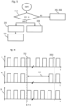
- Fig. 5 depicts an embodiment of the first aspect of the present invention by means of a flow diagram: (a) The time difference ⁇ is determined in step 310 between the clock device 1 and the clock signal 6. If the time difference ⁇ is below or equal to the predetermined threshold x, (d) the first and/or the second time unit may be adjusted in step 340 to the clock device and the clock signal may be provided in step 360 to the application 214 using the first 211 and/or the second time unit 212. If the time difference is above the predetermined threshold x, (b) the first time unit 211 is calibrated in step 320 and, during calibrating the first time unit, (c) the second time unit 212 is used in step 330 for providing the clock signal to the application. After calibrating the first time unit 211, (e) the second time unit 212 may be set in step 350 using the first time unit 211 and/or the clock device 1.
- Fig. 6 schematically depicts by way of example time information of the clock device 3, time information of the first time unit 8, and time information of the second time unit 9 in the form of pulse-per-second signals.
- the dotted line 310 indicates the step of determining the time difference ⁇ between the clock device and the clock signal.
- the time difference ⁇ is larger than the predetermined threshold x and the first time unit is calibrated 320.
- the dotted line 350 indicates the step of setting the second time unit using the first time unit or the clock device. Fig. 6 shows that this can result in a jump of the time information of the second time unit 9.
- setting the second time unit is executed upon receipt of a coordination signal or at a pre-determined time, e.g. between 5s and 120s, in particular between 16s or 30s, after determining the time difference.
- a coordination signal e.g. between 5s and 120s, in particular between 16s or 30s
- the second time unit of a further device is set at a point in time such that the jump does not negatively affect a function e.g. to which the device and the further device transmit time-stamped messages.
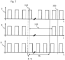
- Fig. 7 schematically depicts by way of example time information of the clock device 3, time information of the first time unit 8, and time information of the second time unit 9 in the form of pulse-per-second signals for a further embodiment of the present invention.
- the time signal or pulse signal is declared as valid during a holdover time period Th and declared as invalid after the holdover time period Th.
- the holdover time period Th can e.g. be 16s or 30s.
- the calibration of the first time unit takes longer than the holdover time period Th; the time signal or pulse signal is then declared to be invalid.
Landscapes
- Engineering & Computer Science (AREA)
- Theoretical Computer Science (AREA)
- Physics & Mathematics (AREA)
- General Engineering & Computer Science (AREA)
- General Physics & Mathematics (AREA)
- Computer Networks & Wireless Communication (AREA)
- Signal Processing (AREA)
- Electric Clocks (AREA)
- Synchronisation In Digital Transmission Systems (AREA)
Claims (14)
- Verfahren zum Bereitstellen eines Taktsignals (6) an eine Anwendung (214), umfassend:Empfangen von Zeitinformation von einer Taktvorrichtung (1);Bestimmen (310) einer Zeitdifferenz (Δ) zwischen der Zeitinformation von der Taktvorrichtung (1) und dem Taktsignal (6);wenn die Zeitdifferenz größer als ein vorbestimmter Schwellenwert (x) ist, Kalibrieren (320) einer ersten Zeiteinheit (211) unter Verwendung der Taktvorrichtung und, während des Kalibrierens der ersten Zeiteinheit, Verwenden (330) einer zweiten Zeiteinheit (212) zum Bereitstellen des Taktsignals (6) an die Anwendung (214); undwenn die Zeitdifferenz (Δ) kleiner oder gleich dem vorbestimmten Schwellenwert (x) ist, Anpassen (340) der ersten Zeiteinheit (211) und/oder der zweiten Zeiteinheit (212) an die Taktvorrichtung (1) und Verwenden (360) der ersten Zeiteinheit (211) und/oder der zweiten Zeiteinheit (212) zum Bereitstellen des Taktsignals (6) an die Anwendung (214).
- Das Verfahren nach Anspruch 1, ferner umfassend:wenn die Zeitdifferenz (Δ) kleiner oder gleich dem vorbestimmten Schwellenwert (x) ist, Koppeln der ersten Zeiteinheit (211) und der zweiten Zeiteinheit (212); undwenn die Zeitdifferenz größer als der vorbestimmte Schwellenwert (x) ist, Entkoppeln der ersten Zeiteinheit (211) und der zweiten Zeiteinheit (212).
- Das Verfahren nach Anspruch 1, ferner umfassend:
wenn die Zeitdifferenz (Δ) größer als der vorbestimmte Schwellenwert (x) ist, vor dem Kalibrieren der ersten Zeiteinheit (211), Erstellen oder Starten der ersten Zeiteinheit (211) oder der zweiten Zeiteinheit (212). - Das Verfahren nach irgendeinem der vorhergehenden Ansprüche, ferner umfassend,
während des Kalibrierens der ersten Zeiteinheit (211), Betreiben der zweiten Zeiteinheit (212) unabhängig von der Taktvorrichtung (1) und der ersten Zeiteinheit (211). - Das Verfahren nach Anspruch 4, ferner umfassend:
während des unabhängigen Betreibens der zweiten Zeiteinheit (212), Erklären des Taktsignals (6) als gültig während eines Holdover-Zeitraums (Th) und Erklären des Taktsignals (6) als ungültig nach dem Holdover-Zeitraum (Th). - Das Verfahren nach irgendeinem der vorhergehenden Ansprüche, wobei die Taktvorrichtung (1) eine Grand-Master-Clock ist.
- Das Verfahren nach irgendeinem der vorhergehenden Ansprüche,
wobei das Taktsignal (6) in Form von Nachrichten gemäß einem Standard aus der Gruppe bestehend aus IEEE 1588, IEC 61588 und IEC 61850-9-3 bereitgestellt wird. - Das Verfahren nach irgendeinem der vorhergehenden Ansprüche, wobei die erste Zeiteinheit (211) und die zweite Zeiteinheit (212) in einem gewöhnlichen Taktgeber oder in einer Boundary-Clock enthalten sind.
- Das Verfahren nach irgendeinem der vorhergehenden Ansprüche, ferner umfassend,
nach dem Kalibrieren der ersten Zeiteinheit (211), Einstellen (350) der zweiten Zeiteinheit (212) unter Verwendung der ersten Zeiteinheit (211) und/oder der Taktvorrichtung (1). - Das Verfahren nach Anspruch 9, wobei
das Einstellen der zweiten Zeiteinheit (211) unter Verwendung der ersten Zeiteinheit (212) und/oder der Taktvorrichtung (1) zu einem vorbestimmten Zeitpunkt nach dem Bestimmen der Zeitdifferenz (Δ) oder nach Empfang eines Koordinationssignals ausgeführt wird. - Vorrichtung (2, 21) zum Bereitstellen eines Taktsignals (6) an eine Anwendung (214), wobei die Vorrichtung eine erste Zeiteinheit (211) und eine zweite Zeiteinheit (212) umfasst, und
wobei die Vorrichtung dazu ausgelegt ist:Zeitinformation von einer Taktvorrichtung (1) zu empfangen und eine Zeitdifferenz (Δ) zwischen dem Taktsignal (6) und der Zeitinformation von der Taktvorrichtung (1) zu bestimmen;wenn die Zeitdifferenz (Δ) größer als ein vorbestimmter Schwellenwert (x) ist, eine erste Zeiteinheit (211) unter Verwendung der Taktvorrichtung zu kalibrieren, und, während des Kalibrierens der ersten Zeiteinheit (211), eine zweite Zeiteinheit (212) zum Bereitstellen des Taktsignals (6) an die Anwendung (214) zu verwenden; und,wenn die Zeitdifferenz (Δ) kleiner oder gleich dem vorbestimmten Schwellenwert (x) ist, die erste Zeiteinheit (211) und/oder die zweite Zeiteinheit (212) an die Taktvorrichtung (1) anzupassen und die erste Zeiteinheit (211) und/oder die zweite Zeiteinheit (212) zu verwenden, um das Taktsignal (6) an die Anwendung (214) bereitzustellen. - Die Vorrichtung (2, 21) nach Anspruch 11, wobei die Vorrichtung (2, 21) ferner dazu ausgelegt ist, während des Kalibrierens der ersten Zeiteinheit (211), die zweite Zeiteinheit (212) unabhängig von der Taktvorrichtung (1) und der ersten Zeiteinheit (211) zu betreiben.
- Die Vorrichtung (2, 21) nach Anspruch 11 oder Anspruch 12, wobei die Vorrichtung ferner dazu ausgelegt ist, die Anwendung (214) auszuführen oder das Taktsignal (6) an eine weitere Vorrichtung bereitzustellen, die dazu ausgelegt ist, die Anwendung auszuführen.
- Die Vorrichtung (2, 21) nach irgendeinem der Ansprüche 11 bis 13, wobei die Vorrichtung eines ist aus der Gruppe bestehend aus einem gewöhnlichen Taktgeber, einer Boundary-Clock, einer Datenerfassungseinheit, einem Switch, einem Router, einem Multiplexer, einer intelligenten elektronischen Vorrichtung zur Automatisierung eines Stromnetzes, einer Merging-Unit, einer Bay-Unit für ein verteiltes Sammelschienenschutzsystem, einem Controller für primäre Umspannwerk-Ausrüstung, einer Phasor-Messeinheit, und einer Kommunikationsschnittstelle eines nichtkonventionellen Messwandlers.
Applications Claiming Priority (1)
| Application Number | Priority Date | Filing Date | Title |
|---|---|---|---|
| EP19173956 | 2019-05-10 |
Publications (2)
| Publication Number | Publication Date |
|---|---|
| EP3736658A1 EP3736658A1 (de) | 2020-11-11 |
| EP3736658B1 true EP3736658B1 (de) | 2024-10-16 |
Family
ID=66529790
Family Applications (1)
| Application Number | Title | Priority Date | Filing Date |
|---|---|---|---|
| EP20173564.4A Active EP3736658B1 (de) | 2019-05-10 | 2020-05-07 | Verfahren und vorrichtung zur bereitstellung eines taktsignals |
Country Status (3)
| Country | Link |
|---|---|
| US (1) | US11614767B2 (de) |
| EP (1) | EP3736658B1 (de) |
| CN (1) | CN111917503B (de) |
Families Citing this family (3)
| Publication number | Priority date | Publication date | Assignee | Title |
|---|---|---|---|---|
| EP4131704A1 (de) * | 2021-08-05 | 2023-02-08 | FRONIUS INTERNATIONAL GmbH | Verfahren und vorrichtung zum kalibrieren eines zeitbasissignals bei einem photovoltaik-wechselrichter |
| EP4318985B1 (de) * | 2022-08-05 | 2025-05-07 | Hitachi Energy Ltd | Koordinierte resynchronisierung von uhren in energienetzsystemen |
| US12050488B2 (en) * | 2022-09-29 | 2024-07-30 | Dell Products L.P. | System and method to maintain clock stability in a complex computing platform |
Family Cites Families (8)
| Publication number | Priority date | Publication date | Assignee | Title |
|---|---|---|---|---|
| US5852728A (en) * | 1995-01-12 | 1998-12-22 | Hitachi, Ltd. | Uninterruptible clock supply apparatus for fault tolerant computer system |
| US8171335B2 (en) * | 2008-09-16 | 2012-05-01 | Mediatek Inc. | Clock timing calibration circuit and clock timing calibration method for calibrating phase difference between different clock signals and related analog-to-digital conversion system using the same |
| US8976778B2 (en) * | 2010-04-21 | 2015-03-10 | Lsi Corporation | Time synchronization using packet-layer and physical-layer protocols |
| CN103036635B (zh) | 2012-12-15 | 2015-11-25 | 辽宁省电力有限公司电力科学研究院 | 基于ieee1588的适应继电保护应用的合并单元同步对时方法 |
| US9362926B2 (en) * | 2014-02-19 | 2016-06-07 | Arbiter Systems, Incorporated | High-reliability holdover method and topologies |
| US9444478B2 (en) | 2014-09-10 | 2016-09-13 | Texas Instruments Incorporated | Voltage regulator with load compensation |
| US10298346B2 (en) * | 2016-06-02 | 2019-05-21 | Cisco Technology, Inc. | Directed acyclic graph optimization based on timing information for generating optimized network clock |
| CN109257814A (zh) * | 2018-09-17 | 2019-01-22 | 上海擎感智能科技有限公司 | 一种时间校准方法及系统 |
-
2020
- 2020-04-30 CN CN202010361592.5A patent/CN111917503B/zh active Active
- 2020-05-07 EP EP20173564.4A patent/EP3736658B1/de active Active
- 2020-05-11 US US16/872,126 patent/US11614767B2/en active Active
Also Published As
| Publication number | Publication date |
|---|---|
| CN111917503B (zh) | 2024-09-06 |
| EP3736658A1 (de) | 2020-11-11 |
| CN111917503A (zh) | 2020-11-10 |
| US20200363832A1 (en) | 2020-11-19 |
| US11614767B2 (en) | 2023-03-28 |
Similar Documents
| Publication | Publication Date | Title |
|---|---|---|
| US9425652B2 (en) | Adaptive holdover timing error estimation and correction | |
| US9590411B2 (en) | Systems and methods for time synchronization of IEDs via radio link | |
| EP2928109B1 (de) | Synchronisationsvorrichtung, synchronisationssystem, drahtlose kommunikationsvorrichtung und synchronisationsverfahren | |
| EP3736658B1 (de) | Verfahren und vorrichtung zur bereitstellung eines taktsignals | |
| US7617408B2 (en) | System and method for providing accurate time generation in a computing device of a power system | |
| RU2567379C1 (ru) | Передача данных по сети с пакетной коммутацией | |
| EP2883316B1 (de) | Latenzbestimmung in substationsnetzwerken | |
| WO2012075881A1 (zh) | 基于ieee1588多从钟的采样值多接口同步系统 | |
| EP3397924A1 (de) | Zeitsignalmanipulation und täuschungserkennung basierend auf der latenzzeit eines kommunikationssystems | |
| CN104505934B (zh) | 一种时钟同步及监测系统 | |
| JP7230690B2 (ja) | 時刻同期プログラム,情報処理装置及び時刻同期方法 | |
| US10320507B2 (en) | Method for determining a propagation time of a telegram in a communication network, and corresponding network components | |
| CN104333426A (zh) | 基于合并单元sv报文采样序号学习的秒脉冲同步方法 | |
| EP3659277A1 (de) | Verfahren, vorrichtung und computerlesbare medien zur synchronisation über ein optisches netzwerk | |
| US12003087B2 (en) | Time synchronization between IEDs of different substations | |
| Antonova et al. | Standard profile for use of IEEE std 1588-2008 precision time protocol (PTP) in power system applications | |
| JP2017189074A (ja) | ディジタル保護継電装置及びディジタル保護継電システム | |
| Qin et al. | High precision time synchronization method of substation based on TSN delay sensing capability | |
| Zhao et al. | Reseach of Time Synchronization Algorithm Based on IEEE1588 in Electric Power System | |
| Peer et al. | The Future of Time: Evolving requirements for Precize Time Synchronization in the Electric Power Industry | |
| Duan et al. | Research of precision time protocol in intelligent switchgears | |
| JP2018102043A (ja) | 保護リレーシステム | |
| Baoyin et al. | Risk analysis and research based on IEEE 1588 in Smart high voltage substation |
Legal Events
| Date | Code | Title | Description |
|---|---|---|---|
| PUAI | Public reference made under article 153(3) epc to a published international application that has entered the european phase |
Free format text: ORIGINAL CODE: 0009012 |
|
| STAA | Information on the status of an ep patent application or granted ep patent |
Free format text: STATUS: THE APPLICATION HAS BEEN PUBLISHED |
|
| AK | Designated contracting states |
Kind code of ref document: A1 Designated state(s): AL AT BE BG CH CY CZ DE DK EE ES FI FR GB GR HR HU IE IS IT LI LT LU LV MC MK MT NL NO PL PT RO RS SE SI SK SM TR |
|
| AX | Request for extension of the european patent |
Extension state: BA ME |
|
| STAA | Information on the status of an ep patent application or granted ep patent |
Free format text: STATUS: REQUEST FOR EXAMINATION WAS MADE |
|
| 17P | Request for examination filed |
Effective date: 20210510 |
|
| RBV | Designated contracting states (corrected) |
Designated state(s): AL AT BE BG CH CY CZ DE DK EE ES FI FR GB GR HR HU IE IS IT LI LT LU LV MC MK MT NL NO PL PT RO RS SE SI SK SM TR |
|
| RAP3 | Party data changed (applicant data changed or rights of an application transferred) |
Owner name: HITACHI ENERGY SWITZERLAND AG |
|
| STAA | Information on the status of an ep patent application or granted ep patent |
Free format text: STATUS: EXAMINATION IS IN PROGRESS |
|
| 17Q | First examination report despatched |
Effective date: 20220705 |
|
| P01 | Opt-out of the competence of the unified patent court (upc) registered |
Effective date: 20230527 |
|
| RAP1 | Party data changed (applicant data changed or rights of an application transferred) |
Owner name: HITACHI ENERGY LTD |
|
| GRAP | Despatch of communication of intention to grant a patent |
Free format text: ORIGINAL CODE: EPIDOSNIGR1 |
|
| STAA | Information on the status of an ep patent application or granted ep patent |
Free format text: STATUS: GRANT OF PATENT IS INTENDED |
|
| INTG | Intention to grant announced |
Effective date: 20240605 |
|
| GRAS | Grant fee paid |
Free format text: ORIGINAL CODE: EPIDOSNIGR3 |
|
| GRAA | (expected) grant |
Free format text: ORIGINAL CODE: 0009210 |
|
| STAA | Information on the status of an ep patent application or granted ep patent |
Free format text: STATUS: THE PATENT HAS BEEN GRANTED |
|
| AK | Designated contracting states |
Kind code of ref document: B1 Designated state(s): AL AT BE BG CH CY CZ DE DK EE ES FI FR GB GR HR HU IE IS IT LI LT LU LV MC MK MT NL NO PL PT RO RS SE SI SK SM TR |
|
| REG | Reference to a national code |
Ref country code: GB Ref legal event code: FG4D |
|
| REG | Reference to a national code |
Ref country code: CH Ref legal event code: EP |
|
| REG | Reference to a national code |
Ref country code: IE Ref legal event code: FG4D |
|
| REG | Reference to a national code |
Ref country code: DE Ref legal event code: R096 Ref document number: 602020039427 Country of ref document: DE |
|
| REG | Reference to a national code |
Ref country code: LT Ref legal event code: MG9D |
|
| REG | Reference to a national code |
Ref country code: NL Ref legal event code: MP Effective date: 20241016 |
|
| REG | Reference to a national code |
Ref country code: AT Ref legal event code: MK05 Ref document number: 1733438 Country of ref document: AT Kind code of ref document: T Effective date: 20241016 |
|
| PG25 | Lapsed in a contracting state [announced via postgrant information from national office to epo] |
Ref country code: NL Free format text: LAPSE BECAUSE OF FAILURE TO SUBMIT A TRANSLATION OF THE DESCRIPTION OR TO PAY THE FEE WITHIN THE PRESCRIBED TIME-LIMIT Effective date: 20241016 |
|
| PG25 | Lapsed in a contracting state [announced via postgrant information from national office to epo] |
Ref country code: NL Free format text: LAPSE BECAUSE OF FAILURE TO SUBMIT A TRANSLATION OF THE DESCRIPTION OR TO PAY THE FEE WITHIN THE PRESCRIBED TIME-LIMIT Effective date: 20241016 |
|
| PG25 | Lapsed in a contracting state [announced via postgrant information from national office to epo] |
Ref country code: PT Free format text: LAPSE BECAUSE OF FAILURE TO SUBMIT A TRANSLATION OF THE DESCRIPTION OR TO PAY THE FEE WITHIN THE PRESCRIBED TIME-LIMIT Effective date: 20250217 Ref country code: IS Free format text: LAPSE BECAUSE OF FAILURE TO SUBMIT A TRANSLATION OF THE DESCRIPTION OR TO PAY THE FEE WITHIN THE PRESCRIBED TIME-LIMIT Effective date: 20250216 Ref country code: HR Free format text: LAPSE BECAUSE OF FAILURE TO SUBMIT A TRANSLATION OF THE DESCRIPTION OR TO PAY THE FEE WITHIN THE PRESCRIBED TIME-LIMIT Effective date: 20241016 |
|
| PG25 | Lapsed in a contracting state [announced via postgrant information from national office to epo] |
Ref country code: FI Free format text: LAPSE BECAUSE OF FAILURE TO SUBMIT A TRANSLATION OF THE DESCRIPTION OR TO PAY THE FEE WITHIN THE PRESCRIBED TIME-LIMIT Effective date: 20241016 |
|
| PG25 | Lapsed in a contracting state [announced via postgrant information from national office to epo] |
Ref country code: BG Free format text: LAPSE BECAUSE OF FAILURE TO SUBMIT A TRANSLATION OF THE DESCRIPTION OR TO PAY THE FEE WITHIN THE PRESCRIBED TIME-LIMIT Effective date: 20241016 |
|
| PG25 | Lapsed in a contracting state [announced via postgrant information from national office to epo] |
Ref country code: ES Free format text: LAPSE BECAUSE OF FAILURE TO SUBMIT A TRANSLATION OF THE DESCRIPTION OR TO PAY THE FEE WITHIN THE PRESCRIBED TIME-LIMIT Effective date: 20241016 |
|
| PG25 | Lapsed in a contracting state [announced via postgrant information from national office to epo] |
Ref country code: NO Free format text: LAPSE BECAUSE OF FAILURE TO SUBMIT A TRANSLATION OF THE DESCRIPTION OR TO PAY THE FEE WITHIN THE PRESCRIBED TIME-LIMIT Effective date: 20250116 |
|
| PG25 | Lapsed in a contracting state [announced via postgrant information from national office to epo] |
Ref country code: LV Free format text: LAPSE BECAUSE OF FAILURE TO SUBMIT A TRANSLATION OF THE DESCRIPTION OR TO PAY THE FEE WITHIN THE PRESCRIBED TIME-LIMIT Effective date: 20241016 Ref country code: AT Free format text: LAPSE BECAUSE OF FAILURE TO SUBMIT A TRANSLATION OF THE DESCRIPTION OR TO PAY THE FEE WITHIN THE PRESCRIBED TIME-LIMIT Effective date: 20241016 Ref country code: GR Free format text: LAPSE BECAUSE OF FAILURE TO SUBMIT A TRANSLATION OF THE DESCRIPTION OR TO PAY THE FEE WITHIN THE PRESCRIBED TIME-LIMIT Effective date: 20250117 |
|
| PG25 | Lapsed in a contracting state [announced via postgrant information from national office to epo] |
Ref country code: PL Free format text: LAPSE BECAUSE OF FAILURE TO SUBMIT A TRANSLATION OF THE DESCRIPTION OR TO PAY THE FEE WITHIN THE PRESCRIBED TIME-LIMIT Effective date: 20241016 |
|
| PG25 | Lapsed in a contracting state [announced via postgrant information from national office to epo] |
Ref country code: RS Free format text: LAPSE BECAUSE OF FAILURE TO SUBMIT A TRANSLATION OF THE DESCRIPTION OR TO PAY THE FEE WITHIN THE PRESCRIBED TIME-LIMIT Effective date: 20250116 |
|
| PG25 | Lapsed in a contracting state [announced via postgrant information from national office to epo] |
Ref country code: SM Free format text: LAPSE BECAUSE OF FAILURE TO SUBMIT A TRANSLATION OF THE DESCRIPTION OR TO PAY THE FEE WITHIN THE PRESCRIBED TIME-LIMIT Effective date: 20241016 |
|
| PGFP | Annual fee paid to national office [announced via postgrant information from national office to epo] |
Ref country code: DE Payment date: 20250521 Year of fee payment: 6 |
|
| PG25 | Lapsed in a contracting state [announced via postgrant information from national office to epo] |
Ref country code: DK Free format text: LAPSE BECAUSE OF FAILURE TO SUBMIT A TRANSLATION OF THE DESCRIPTION OR TO PAY THE FEE WITHIN THE PRESCRIBED TIME-LIMIT Effective date: 20241016 |
|
| PGFP | Annual fee paid to national office [announced via postgrant information from national office to epo] |
Ref country code: GB Payment date: 20250527 Year of fee payment: 6 |
|
| REG | Reference to a national code |
Ref country code: DE Ref legal event code: R097 Ref document number: 602020039427 Country of ref document: DE |
|
| PG25 | Lapsed in a contracting state [announced via postgrant information from national office to epo] |
Ref country code: EE Free format text: LAPSE BECAUSE OF FAILURE TO SUBMIT A TRANSLATION OF THE DESCRIPTION OR TO PAY THE FEE WITHIN THE PRESCRIBED TIME-LIMIT Effective date: 20241016 |
|
| PGFP | Annual fee paid to national office [announced via postgrant information from national office to epo] |
Ref country code: FR Payment date: 20250528 Year of fee payment: 6 |
|
| PG25 | Lapsed in a contracting state [announced via postgrant information from national office to epo] |
Ref country code: RO Free format text: LAPSE BECAUSE OF FAILURE TO SUBMIT A TRANSLATION OF THE DESCRIPTION OR TO PAY THE FEE WITHIN THE PRESCRIBED TIME-LIMIT Effective date: 20241016 |
|
| PG25 | Lapsed in a contracting state [announced via postgrant information from national office to epo] |
Ref country code: SK Free format text: LAPSE BECAUSE OF FAILURE TO SUBMIT A TRANSLATION OF THE DESCRIPTION OR TO PAY THE FEE WITHIN THE PRESCRIBED TIME-LIMIT Effective date: 20241016 |
|
| PG25 | Lapsed in a contracting state [announced via postgrant information from national office to epo] |
Ref country code: CZ Free format text: LAPSE BECAUSE OF FAILURE TO SUBMIT A TRANSLATION OF THE DESCRIPTION OR TO PAY THE FEE WITHIN THE PRESCRIBED TIME-LIMIT Effective date: 20241016 |
|
| PG25 | Lapsed in a contracting state [announced via postgrant information from national office to epo] |
Ref country code: IT Free format text: LAPSE BECAUSE OF FAILURE TO SUBMIT A TRANSLATION OF THE DESCRIPTION OR TO PAY THE FEE WITHIN THE PRESCRIBED TIME-LIMIT Effective date: 20241016 |
|
| PLBE | No opposition filed within time limit |
Free format text: ORIGINAL CODE: 0009261 |
|
| STAA | Information on the status of an ep patent application or granted ep patent |
Free format text: STATUS: NO OPPOSITION FILED WITHIN TIME LIMIT |
|
| PG25 | Lapsed in a contracting state [announced via postgrant information from national office to epo] |
Ref country code: SE Free format text: LAPSE BECAUSE OF FAILURE TO SUBMIT A TRANSLATION OF THE DESCRIPTION OR TO PAY THE FEE WITHIN THE PRESCRIBED TIME-LIMIT Effective date: 20241016 |
|
| 26N | No opposition filed |
Effective date: 20250717 |
|
| REG | Reference to a national code |
Ref country code: CH Ref legal event code: H13 Free format text: ST27 STATUS EVENT CODE: U-0-0-H10-H13 (AS PROVIDED BY THE NATIONAL OFFICE) Effective date: 20251223 |
|
| PG25 | Lapsed in a contracting state [announced via postgrant information from national office to epo] |
Ref country code: LU Free format text: LAPSE BECAUSE OF NON-PAYMENT OF DUE FEES Effective date: 20250507 |
|
| PG25 | Lapsed in a contracting state [announced via postgrant information from national office to epo] |
Ref country code: CH Free format text: LAPSE BECAUSE OF NON-PAYMENT OF DUE FEES Effective date: 20250531 |
|
| REG | Reference to a national code |
Ref country code: BE Ref legal event code: MM Effective date: 20250531 |
|
| PG25 | Lapsed in a contracting state [announced via postgrant information from national office to epo] |
Ref country code: MC Free format text: LAPSE BECAUSE OF FAILURE TO SUBMIT A TRANSLATION OF THE DESCRIPTION OR TO PAY THE FEE WITHIN THE PRESCRIBED TIME-LIMIT Effective date: 20241016 |