EP3736581B1 - Test device for testing electrical modules, use of a test device and method for testing electrical modules - Google Patents
Test device for testing electrical modules, use of a test device and method for testing electrical modules Download PDFInfo
- Publication number
- EP3736581B1 EP3736581B1 EP20173428.2A EP20173428A EP3736581B1 EP 3736581 B1 EP3736581 B1 EP 3736581B1 EP 20173428 A EP20173428 A EP 20173428A EP 3736581 B1 EP3736581 B1 EP 3736581B1
- Authority
- EP
- European Patent Office
- Prior art keywords
- receiving unit
- module
- module receiving
- test device
- support member
- Prior art date
- Legal status (The legal status is an assumption and is not a legal conclusion. Google has not performed a legal analysis and makes no representation as to the accuracy of the status listed.)
- Active
Links
- 238000012360 testing method Methods 0.000 title claims description 137
- 238000000034 method Methods 0.000 title claims description 4
- 238000010998 test method Methods 0.000 claims description 4
- 239000004020 conductor Substances 0.000 description 2
- 230000007547 defect Effects 0.000 description 2
- 230000001419 dependent effect Effects 0.000 description 1
- 238000011990 functional testing Methods 0.000 description 1
- 230000010365 information processing Effects 0.000 description 1
- 239000004065 semiconductor Substances 0.000 description 1
- 238000005476 soldering Methods 0.000 description 1
Images


Classifications
-
- G—PHYSICS
- G01—MEASURING; TESTING
- G01R—MEASURING ELECTRIC VARIABLES; MEASURING MAGNETIC VARIABLES
- G01R31/00—Arrangements for testing electric properties; Arrangements for locating electric faults; Arrangements for electrical testing characterised by what is being tested not provided for elsewhere
- G01R31/28—Testing of electronic circuits, e.g. by signal tracer
- G01R31/2801—Testing of printed circuits, backplanes, motherboards, hybrid circuits or carriers for multichip packages [MCP]
- G01R31/2806—Apparatus therefor, e.g. test stations, drivers, analysers, conveyors
Definitions
- the invention relates to a test device for testing electrical modules, the use of this test device and a method for testing electrical modules using the test device.
- Test devices for testing electrical modules are used to subject an electrical module to be tested to a functional test and/or load test.
- the test device has a module receiving unit into which the module to be tested is inserted.
- the module to be tested is electrically connected to the test device through the module receiving unit.
- a test procedure for testing the module to be tested can then be carried out using a testing device coupled to the test device.
- input signals can be entered into the module to be tested.
- Output signals then emitted by the module to be tested can be compared with reference signals by the testing device in order to verify that the module to be tested is free of errors.
- it is desirable to expose the module to be tested to various test parameters for example different temperatures, air pressures, vibrations, etc.
- test devices only allow only a single module to be tested to be tested. However, it is desirable to test different modules simultaneously so that the different modules are exposed to the same test parameters during a test. Furthermore, it is desirable to reduce changeover times, i.e. the time it takes to change a module.
- a camera module test base which comprises: a first circuit board with which a first base with a mounting unit on which a camera module is mounted, is combined; a second board with which a second socket is combined; a rotating hinge connecting the first and second bases together to be rotated; and a connector installed in the second base and conductively connected to a camera module mounted on the mounting unit while the first and second bases are closed.
- the US 2014/159757 A1 discloses a system for testing information processing systems.
- the system includes a top cover with a memory circuit and a bottom platform for receiving a test printed circuit board assembly (PCBA) with a slot.
- PCBA printed circuit board assembly
- the system includes a sensor that determines the relative position of the memory circuit and the slot; and a host controller connected to the test PCBA and sensor via a port.
- the US 2007/079187 A1 discloses a system for testing memory modules having a rotating circuit board mounting section with multiple mounting surfaces positioned in different planes and connected about an axis to form a rotatable structure, with at least one circuit board mounted on each mounting surface, an input / output part, a rotary motor coupled to a rotary shaft for rotating the rotatable structure, and a central controller electrically connected to the circuit boards.
- the WO 01/69268 A2 relates to an integrated circuit test socket comprising: a socket body for establishing an electrical connection between leads or pads of an integrated circuit and a load card.
- a lid assembly is pivotally connected to the base body by a hinge and is rotatable between a closed position and an open position. The lid assembly can be removed from the base body without tools.
- test device with which various modules can be tested quickly and reliably and which enables short changeover times. Furthermore, it is the object of the invention to propose a corresponding test method and a use of the test device.
- the disclosed test device makes it possible for several modules, namely the module to be tested and the further module to be tested, to be tested simultaneously.
- the test device makes it possible to simultaneously test the module arranged in the inner module receiving unit and the module arranged in the at least one permanently accessible module receiving unit, so that both modules can be exposed to the same test parameters.
- the test device can have a test module for testing the modules or the test device is designed to be connected to a test device.
- input signals can be provided for the modules to be tested, namely for the module arranged in the inner module receiving unit and for the module arranged in the at least one permanently accessible module receiving unit.
- Output signals from the respective modules can then be compared with corresponding reference signals using the testing device in order to determine whether the modules to be tested are error-free.
- the proposed test device enables the module arranged in the at least one permanently accessible module receiving unit to be exchangeable even though the first and second support members are in the operating position.
- the position of the first and second support members does not have to be changed for an exchange of the module arranged in the at least one permanently accessible module receiving unit, which shortens changeover times of the test device.
- the at least one permanently accessible module receiving unit is arranged on the test device in such a way that the at least one permanently accessible module receiving unit also allows an exchange of the further module to be tested in a test configuration position of the test device, which enables an exchange of the module to be tested arranged in the inner module receiving unit enabled.
- test configuration position is understood to mean an arrangement of the first support member and the second support member relative to one another, which makes it possible to exchange or accommodate a module arranged in the inner module receiving unit.
- the at least one permanently accessible module receiving unit for modules to be tested, which have a higher error rate and therefore may have to be replaced more often than modules which are accommodated by the inner module receiving unit. Consequently, it is possible to further reduce changeover times of the test device.
- the test device is designed to be in the inner To electrically connect the module arranged in the module receiving unit to the module arranged in the at least one permanently accessible module receiving unit.
- it can be provided to electrically connect contacting means of the inner module receiving unit, which are designed for electrical contact with the module to be tested, directly to contacting means of the at least one permanently accessible module receiving unit, which are designed to electrically contact the further module to be tested.
- Direct electrical connection means connecting the contacting means of the inner module receiving unit to the contacting means of the at least one permanently accessible module receiving unit via an electrical conductor. It is preferably provided that the electrical connection does not take place via any circuits of the test device.
- the module to be tested in the inner module receiving unit can be a control module, which is electrically connected directly to a camera module, for example a charge-coupled device (CCD), as a further module to be tested in the at least one permanently accessible module receiving unit.
- a control module which is electrically connected directly to a camera module, for example a charge-coupled device (CCD), as a further module to be tested in the at least one permanently accessible module receiving unit. This can ensure that the control module directly controls the camera module.
- CCD charge-coupled device
- the first support member spans a surface which runs essentially horizontally in the operating position.
- the second support member spans a surface which is arranged opposite the first surface in the operating position.
- the first support member and the second support member can be arranged substantially parallel to one another in the operating position.
- the inner module receiving unit can be arranged on a first side of the first support member, which is opposite the second support member in the operating position. Furthermore, the inner module receiving unit be arranged on the first side of the first support member, so that in the operating position the inner module receiving unit is arranged between the first support member and the second support member. Alternatively, the inner module receiving unit can be arranged in a recess in the first support member, so that the inner module receiving unit is arranged at least in sections between the first support member and the second support member in the operating position. Furthermore, in the operating position, the module accommodated in the inner module receiving unit is fixed or secured in the inner module receiving unit by means of the second support member.
- first support member and the second support member are designed to be pivotable relative to one another and/or designed to be displaceable parallel to one another in order to arrange the first support member and the second support member in the operating position.
- the two mutually movable support members are designed to enable access to the inner module receiving unit.
- the first support member and the second support member can be moved relative to one another in such a way that access to the module to be tested in the inner module receiving unit is possible in the test configuration position.
- the term “test configuration position” also means that it is possible to insert or exchange the modules in the inner module receiving unit and in the at least one permanently accessible module receiving unit.
- the at least one permanently accessible module receiving unit is designed as a first module receiving unit which is arranged on the second support member.
- the first module receiving unit can be arranged on the second support member in such a way that in the operating position of the test device, the first module receiving unit is accessible for module replacement.
- the first module receiving unit can be on a first side of the second support member be arranged, which faces away from the first support member in the operating position.
- the first module receiving unit can be arranged on the second support member in such a way that in the operating position, the position of the inner module receiving unit on the first support member and the position of the first module receiving unit on the second support member are congruent.
- the first module receiving unit can be arranged at least in sections in a recess in the second support member, so that in the operating position the first module receiving unit advantageously secures or fixes the module to be tested in the inner module receiving unit.
- the first module receiving unit preferably has contacting means which are designed to electrically contact a module provided for the first module receiving unit with a module provided for the inner module receiving unit.
- the contacting means can be designed as an electrical conductor which electrically connects the module provided for the first module receiving unit directly to the module provided for the inner module receiving unit.
- the contacting means enables direct electrical contacting of both modules without the need for additional circuits or circuit elements of the test device. This makes it possible to test functionally related modules with each other without having to control them individually via the test device.
- the contacting means of the first module receiving unit are designed as spring contact pins in order to electrically connect the module arranged in the inner module receiving unit to the module arranged in the first module receiving unit.
- the contacting means are designed on both sides as spring contact pins, so that a first end of one of the spring contact pins electrically contacts the module arranged in the inner module receiving unit and a second end of the spring contact pins electrically contacts that in the first Module arranged in the module receiving unit is electrically contacted.
- the first module receiving unit has a securing means which is designed to secure a module provided for the first module receiving unit in the first module receiving unit.
- the securing means can be designed to be pivotable with the first module receiving unit. Furthermore, by assuming a securing position of the securing means, it is ensured that the module arranged in the first module receiving unit is secured and electrical contact is established between the contacting means and the module.
- the at least one permanently accessible module receiving unit is designed as a second module receiving unit which is arranged on the first support member.
- the test device can be designed so that the second module receiving unit is accessible for a module exchange in the operating position of the test device.
- the second support member provides a recess so that the second module receiving unit is not covered by the second support member in the operating position or access to the second module receiving unit is enabled in the operating position.
- the second module receiving unit is arranged on the first side of the first support member.
- the inner module receiving unit, the first module receiving unit and the second module receiving unit are electrically connected to one another, so that the modules arranged in the corresponding module receiving units can be tested with one another.
- the recess in the second support member is designed such that access to the second module receiving unit is enabled in the operating position.
- the second support member is designed such that access to the second module receiving unit is enabled in the test configuration position.
- the second module receiving unit is designed to electrically contact a module provided for the second module receiving unit by means of a replaceable adapter module.
- the adapter module is interposed between the second module receiving unit and the module provided for the second module receiving unit.
- the adapter module can have module-receiving unit-specific contacting means with which the adapter module and the second module receiving unit are electrically connected.
- the adapter module can have module-specific contacting means with which the adapter module and the module provided for the second module receiving unit are electrically connected.
- the adapter module is preferably used to connect modules to the second module receptacle that have an electrical connection that cannot be easily detached, for example plug connectors or plug modules.
- Directly connecting such plug modules to the second module receiving unit and repeatedly releasing the plug modules leads to high physical stress on the second module receiving unit and thus to a high failure rate of the second module receiving unit.
- the stress on the second module receiving unit can be reduced, since the stress is compensated for by the adapter module.
- the first support member and the second support member are connected to each other by means of a movement support member.
- the movement support member is further configured to support the movement of the first support member and the second support member to assume the operating position and/or test configuration position.
- the movement support member can be designed as a gas pressure spring, which supports the assumption of the test configuration position.
- the movement support member is designed to withstand high temperatures in order to expose the test device to appropriate test parameters can be.
- the movement support member can preferably be designed to be usable for a temperature range of 0°C to 50°C, of -10°C to 80°C and particularly preferably of -40°C to 125°C.
- the movement support member can be designed as a gas pressure spring.
- several movement support members can also be provided, so that the test device has, for example, at least two gas pressure springs.
- the first support member and the second support member are connected to each other by means of a hinge and the test device may have a locking unit for locking the first support member and the second support member in the operating position and/or test configuration position.
- the test device may have a locking unit for locking the first support member and the second support member in the operating position and/or test configuration position.
- a further aspect of the invention relates to the use of a test device according to the above statements for testing electrical modules.
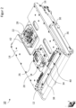
- Figure 1 shows a perspective view of a preferred embodiment of a test device 10 for testing electrical modules.
- the test device 10 has a first support member 12, which is connected to a second support member 14 by means of a connecting element 16, so that the first support member 12 and the second support member 14 are designed to be movable relative to one another.
- the connecting element 16 can be designed, for example, as a hinge.
- the first support member 12 and the second support member 14 are designed to be pivotable relative to one another by means of the connecting element 16.
- the first support member 12 spans an area which is defined, for example, by a circuit board 13.
- the circuit board 13 can also be arranged on a frame 36.
- an inner module receiving unit 18 is arranged, which is designed to accommodate a module 24 to be tested.
- the inner module receiving unit 18 also has contacting means for electrically contacting the module 24 to be accommodated, so that an electrical connection can be established between the test device 10 and the module 24 by means of the contacting means.
- the contacting means can preferably be designed as spring contact pins.
- Figure 1 shows an example of a test configuration position of the test device 10, in which the module 24 of the inner module receiving unit 18 is accessible in order to be able to exchange the module 24.
- the second support member 14 spans a surface, on which a first module receiving unit 20 is designed as a permanently accessible module receiving unit.
- a second module receiving unit 22 which is arranged on the first side 38 of the first support member 12 and which is also designed as a permanently accessible module receiving unit.
- a permanently accessible module receiving unit is understood to mean a module receiving unit which, among other things, makes it possible to provide access to the recorded module in an operating position of the test device 10, so that a module exchange of a module accommodated in a permanently accessible module receiving unit is possible.
- the operating position of the test device 10 is explained.
- the first support member 12 and the second support member 14 are arranged opposite one another, preferably in parallel opposite one another.
- the first side 38 of the first support member 12 is arranged opposite the second support member 14 in the operating position.
- the second support member 14 covers the inner module receiving unit 18, so that the inner module receiving unit 18 is inaccessible in the operating position for replacing the module 24 to be tested.
- the first module receiving unit 20 is arranged on a side of the second support member 14, which faces away from the first support member 12 in the operating position.
- a module 26 to be tested which is accommodated by the first module receiving unit 20, can also be exchanged in the operating position of the test device 10.
- the second support member 14 has a first recess 40 in which the first module receiving unit 20 is arranged at least in sections.
- the first module receiving unit 20 is preferably positioned on the second support member 14 in such a way that in the operating position of the test device 10, the position of the first module receiving unit 20 is congruent with the position of the inner module receiving unit 18. This makes it possible for the first module receiving unit 20 to secure or fix the module 24 in the inner module receiving unit 18 in the operating position of the test device 10.
- the second module receiving unit 20 has a movable securing means 34, with which a module 26 accommodated in the first module receiving unit 20 can be secured or fixed.
- the second support member 14 has a second recess 42, which makes the second module receiving unit 22 accessible for module replacement in the operating position of the test device 10.
- Figure 3 shows a cross-sectional view of the test device 10, which is in the operating position.
- This shows Figure 3 the inner module receiving unit 18 arranged on the first support member 12, which has received a module 24 to be tested.
- the inner module receiving unit 18 also has first contacting means 44 in order to electrically connect the received module 24 to the test device 10.
- Fig. 3 the first module receiving unit 20 arranged on the second support member 14, in which a module 26 to be tested is arranged.
- the module 26 is secured or fixed in the first module receptacle 20 by the securing means 34.
- the first module receiving unit 20 has second contacting means 46, which are designed to directly electrically connect the module 24 arranged in the inner module receiving unit 18 to the module 26 arranged in the first module receiving unit 20.
- the second contacting means 46 can have spring contact pins which are designed to establish electrical contact between the module 24 and the module 26. This makes it possible to establish electrical contact between the module 24 in the inner module receiving unit 18 and the module 26 in the first module receiving unit 18 by assuming the operating position of the test device 10.
- FIG 4 shows a perspective view of the second module receiving unit 28, which, as in the Figures 1 and 2 shown, is arranged on the first support member 12.
- the second module receiving unit 22 is arranged on the first side 38 of the first support member 12.
- the second module receiving unit 22 has a first module receiving unit section 48 and a second module receiving unit section 50, which can be connected to one another.
- the first module receiving unit section 48 is arranged on the first support member 12.
- the second module receiving unit 22 is designed to accommodate an adapter module 52, which can be arranged between the first module receiving unit section 48 and the second module receiving unit section 50.
- the adapter module 52 is secured between the first module receiving unit section 48 and the second module receiving unit section 50, so that the adapter module 52 remains in the second module receiving unit 22 when the module 28 is removed.
- the first module receiving unit section 48 has third contacting means (not shown) in order to electrically connect the test device 10 to an electrical contact 54 of the adapter module 52.
- the electrical contact 54 of the adapter module 52 is further designed to electrically connect the module 28 accommodated in the second module receiving unit 22 to the test device 10.
- the adapter module 52 can be quickly replaced in the event of a defect by detaching the second module receiving unit section 50 from the first module receiving unit section 48.
- the third contacting means are designed to be detachable. In other words, the third contacting means enable electrical contact by pressing the adapter module 52 onto the first module receiving unit section 48.
- the second module receiving unit section 50 has a receiving opening 56, through which the module 28 to be tested is received in the second module receiving unit 22, in particular by the adapter module 52.
- the test device 10 as in the Figures 1 and 2 1 shows a movement support member 30 that assists in moving the first support member 12 and the second support member 14 to the operating position and/or to the test configuration position.
- the movement support member 30 can be designed as a gas pressure spring 30, which is particularly temperature-resistant.
- the gas pressure spring 30 can preferably be designed to be usable for a temperature range of 0°C to 50°C, of -10°C to 80°C and particularly preferably of -40°C to 125°C.
- the test device 10 has a locking unit 32, which enables the first support member 12 and the second support member 14 to be securely locked in the operating position and/or in the test configuration position.
Description
Die Erfindung betrifft eine Testvorrichtung zum Testen elektrischer Module, die Verwendung dieser Testvorrichtung und ein Verfahren zum Testen elektrischer Module mittels der Testvorrichtung.The invention relates to a test device for testing electrical modules, the use of this test device and a method for testing electrical modules using the test device.
Testvorrichtungen zum Testen elektrischer Module, beispielsweise Halbleiterbausteine und oder Printed Circuit Boards (PCB), werden dazu genutzt, um ein zu testendes elektrisches Modul einem Funktionstest und/oder Belastungstest zu unterziehen. Dazu kann vorgesehen sein, dass die Testvorrichtung eine Modulaufnahmeeinheit aufweist, in die das zu testende Modul eingelegt wird. Durch die Modulaufnahmeeinheit wird das zu testende Modul mit der Testvorrichtung elektrisch verbunden. Anschließend kann eine Testprozedur zum Prüfen des zu testenden Moduls mit einer mit der Testvorrichtung gekoppelten Prüfvorrichtung durchgeführt werden. Beispielsweise können in das zu testende Modul Eingabesignale eingegeben werden. Daraufhin durch das zu testende Modul ausgegebene Ausgabesignale können durch die Prüfvorrichtung mit Referenzsignalen verglichen werden, um die Fehlerfreiheit des zu testenden Moduls zu verifizieren. Ferner ist es wünschenswert, das zu testende Modul diverser Testparameter, beispielsweise verschiedene Temperaturen, Luftdrücke, Vibrationen usw. auszusetzen.Test devices for testing electrical modules, for example semiconductor components and/or printed circuit boards (PCB), are used to subject an electrical module to be tested to a functional test and/or load test. For this purpose, it can be provided that the test device has a module receiving unit into which the module to be tested is inserted. The module to be tested is electrically connected to the test device through the module receiving unit. A test procedure for testing the module to be tested can then be carried out using a testing device coupled to the test device. For example, input signals can be entered into the module to be tested. Output signals then emitted by the module to be tested can be compared with reference signals by the testing device in order to verify that the module to be tested is free of errors. Furthermore, it is desirable to expose the module to be tested to various test parameters, for example different temperatures, air pressures, vibrations, etc.
Bekannte Testvorrichtungen lassen jedoch lediglich zu, dass nur ein einzelnes zu testendes Modul getestet werden. Es ist jedoch wünschenswert, verschiedene Module gleichzeitig zu testen, so dass die verschiedenen Module während eines Tests den gleichen Testparametern ausgesetzt sind. Des Weiteren ist es erstrebenswert, Umrüstzeiten, d.h. die Dauer der Durchführung eines Modulwechsels, zu reduzieren.However, known test devices only allow only a single module to be tested to be tested. However, it is desirable to test different modules simultaneously so that the different modules are exposed to the same test parameters during a test. Furthermore, it is desirable to reduce changeover times, i.e. the time it takes to change a module.
Ferner ist aus der
Die
Die
Die
Es ist daher Aufgabe der vorliegenden Erfindung, eine Testvorrichtung bereitzustellen, mit der verschiedene Module schnell und zuverlässig getestet werden können und welche kurze Umrüstzeiten ermöglicht. Des Weiteren ist es Aufgabe der Erfindung, ein entsprechendes Testverfahren und eine Verwendung der Testvorrichtung vorzuschlagen.It is therefore the object of the present invention to provide a test device with which various modules can be tested quickly and reliably and which enables short changeover times. Furthermore, it is the object of the invention to propose a corresponding test method and a use of the test device.
Die Aufgabe wird durch die Gegenstände der unabhängigen Ansprüche gelöst. Bevorzugte Ausführungsformen sind in den abhängigen Ansprüchen definiert.The task is solved by the subjects of the independent claims. Preferred embodiments are defined in the dependent claims.
Ein Aspekt betrifft eine Testvorrichtung zum Testen elektrischer Module, aufweisend:
- ein erstes Unterstützungsglied und ein zweites Unterstützungsglied, die zueinander beweglich ausgebildet sind und in einer Betriebsposition der Testvorrichtung zum Testen der elektrischen Module gegenüberliegend angeordnet sind;
- eine an dem ersten Unterstützungsglied angeordnete innere Modulaufnahmeeinheit zum elektrischen Kontaktieren eines zu testenden Moduls, wobei die innere Modulaufnahmeeinheit in der Betriebsposition zum Austauschen des zu testenden Moduls unzugänglich ist; und
- mindestens eine permanent zugängliche Modulaufnahmeeinheit zum elektrischen Kontaktieren eines weiteren zu testenden Moduls,
- wobei die mindestens eine permanent zugängliche Modulaufnahmeeinheit derart an der Testvorrichtung angeordnet ist, dass die mindestens eine permanent zugängliche Modulaufnahmeeinheit in der Betriebsposition zum Austauschen des zu testenden Moduls zugänglich ist, und
- wobei die innere Modulaufnahmeeinheit und die mindestens eine permanent zugängliche Modulaufnahmeeinheit dazu ausgebildet sind, die zu testenden Module elektrisch mit der Testvorrichtung zu verbinden.
- a first support member and a second support member, which are designed to be movable relative to one another and are arranged opposite one another in an operating position of the test device for testing the electrical modules;
- an inner module receiving unit arranged on the first support member for electrically contacting a module to be tested, the inner module receiving unit being inaccessible in the operating position for replacing the module to be tested; and
- at least one permanently accessible module receiving unit for electrically contacting another module to be tested,
- wherein the at least one permanently accessible module receiving unit is arranged on the test device in such a way that the at least one permanently accessible module receiving unit is accessible in the operating position for replacing the module to be tested, and
- wherein the inner module receiving unit and the at least one permanently accessible module receiving unit are designed to electrically connect the modules to be tested to the test device.
Die offenbarte Testvorrichtung ermöglicht es, dass mehrere Module, nämlich das zu testende Modul and das weitere zu testende Modul, gleichzeitig getestet werden können. Insbesondere ermöglicht es die Testvorrichtung, das in der inneren Modulaufnahmeeinheit angeordnete Modul und das in der mindestens einen permanent zugänglichen Modulaufnahmeeinheit angeordnete Modul gleichzeitig zu testen, so dass beide Module gleichen Testparametern ausgesetzt werden können.The disclosed test device makes it possible for several modules, namely the module to be tested and the further module to be tested, to be tested simultaneously. In particular, the test device makes it possible to simultaneously test the module arranged in the inner module receiving unit and the module arranged in the at least one permanently accessible module receiving unit, so that both modules can be exposed to the same test parameters.
Ferner kann die Testvorrichtung zum Testen der Module ein Prüfmodul aufweisen oder die Testvorrichtung ist derart ausgebildet, um mit einer Prüfvorrichtung verbunden zu werden. Mittels der Prüfvorrichtung können Eingabesignale für die zu testenden Module, nämlich für das in der inneren Modulaufnahmeeinheit angeordnete Modul und für das in der mindestens einen permanent zugänglichen Modulaufnahmeeinheit angeordnete Modul, bereitgestellt werden. Daraufhin ausgegebene Ausgabesignale der jeweiligen Module können mittels der Prüfvorrichtung mit entsprechenden Referenzsignalen verglichen werden, um zu bestimmen, ob die zu testenden Module fehlerfrei sind.Furthermore, the test device can have a test module for testing the modules or the test device is designed to be connected to a test device. By means of the testing device, input signals can be provided for the modules to be tested, namely for the module arranged in the inner module receiving unit and for the module arranged in the at least one permanently accessible module receiving unit. Output signals from the respective modules can then be compared with corresponding reference signals using the testing device in order to determine whether the modules to be tested are error-free.
Des Weiteren ermöglicht die vorgeschlagene Testvorrichtung, dass das in der mindestens einen permanent zugänglichen Modulaufnahmeeinheit angeordnete Modul austauschbar ist obwohl die ersten und zweiten Unterstützungsglieder sich in der Betriebsposition befinden. Somit muss die Position der ersten und zweiten Unterstützungsglieder für einen Austausch des in der mindestens einen permanent zugänglichen Modulaufnahmeeinheit angeordneten Moduls nicht verändert werden, wodurch Umrüstzeiten der Testvorrichtung verkürzt werden.Furthermore, the proposed test device enables the module arranged in the at least one permanently accessible module receiving unit to be exchangeable even though the first and second support members are in the operating position. Thus, the position of the first and second support members does not have to be changed for an exchange of the module arranged in the at least one permanently accessible module receiving unit, which shortens changeover times of the test device.
Vorzugsweise ist die mindestens eine permanent zugängliche Modulaufnahmeeinheit derart an der Testvorrichtung angeordnet ist, dass die mindestens eine permanent zugängliche Modulaufnahmeeinheit auch in einer Testkonfigurationsposition der Testvorrichtung, welche einen Austausch des in der inneren Modulaufnahmeeinheit angeordneten zu testenden Moduls ermöglicht, einen Austausch des Weiteren zu testenden Moduls ermöglicht. Unter dem Begriff "Testkonfigurationsposition" wird eine Anordnung des ersten Unterstützungsglieds und des zweiten Unterstützungsglieds zu einander verstanden, welche es ermöglicht, ein in der inneren Modulaufnahmeeinheit angeordnetes Modul zu tauschen bzw. aufzunehmen.Preferably, the at least one permanently accessible module receiving unit is arranged on the test device in such a way that the at least one permanently accessible module receiving unit also allows an exchange of the further module to be tested in a test configuration position of the test device, which enables an exchange of the module to be tested arranged in the inner module receiving unit enabled. The term “test configuration position” is understood to mean an arrangement of the first support member and the second support member relative to one another, which makes it possible to exchange or accommodate a module arranged in the inner module receiving unit.
Ferner ist es vorteilhaft, die mindestens eine permanent zugängliche Modulaufnahmeeinheit für zu testende Module vorzusehen, welche eine höhere Fehlerrate aufweisen und somit gegebenenfalls öfter getauscht werden müssen als Module, welche von der inneren Modulaufnahmeeinheit aufgenommen sind. Folglich ist es möglich, Umrüstzeiten der Testvorrichtung weiter zu reduzieren.Furthermore, it is advantageous to provide the at least one permanently accessible module receiving unit for modules to be tested, which have a higher error rate and therefore may have to be replaced more often than modules which are accommodated by the inner module receiving unit. Consequently, it is possible to further reduce changeover times of the test device.
Vorzugsweise ist die Testvorrichtung dazu ausgebildet, dass in der inneren Modulaufnahmeeinheit angeordnete Modul mit dem in der mindestens einen permanent zugänglichen Modulaufnahmeeinheit angeordneten Modul elektrisch zu verbinden. Insbesondere kann vorgesehen sein, Kontaktierungsmittel der inneren Modulaufnahmeeinheit, welche zum elektrischen kontaktieren des zu testenden Moduls ausgebildet sind, direkt mit Kontaktierungsmitteln der mindestens einen permanent zugänglichen Modulaufnahmeeinheit, welche zum elektrischen kontaktieren des Weiteren zu testenden Moduls ausgebildet sind, elektrisch zu verbinden. Unter direkt elektrisch zu verbinden wird verstanden, die Kontaktierungsmittel der inneren Modulaufnahmeeinheit mit den Kontaktierungsmitteln der mindestens einen permanent zugänglichen Modulaufnahmeeinheit über einen elektrischen Leiter zu verbinden. Bevorzugt ist vorgesehen, dass die elektrische Verbindung nicht über etwaige Schaltungen der Testvorrichtung erfolgt.Preferably, the test device is designed to be in the inner To electrically connect the module arranged in the module receiving unit to the module arranged in the at least one permanently accessible module receiving unit. In particular, it can be provided to electrically connect contacting means of the inner module receiving unit, which are designed for electrical contact with the module to be tested, directly to contacting means of the at least one permanently accessible module receiving unit, which are designed to electrically contact the further module to be tested. Direct electrical connection means connecting the contacting means of the inner module receiving unit to the contacting means of the at least one permanently accessible module receiving unit via an electrical conductor. It is preferably provided that the electrical connection does not take place via any circuits of the test device.
Auf vorteilhafte Weise können so funktional zusammengehörige Module direkt miteinander verbunden und getestet werden, ohne dass weitere Schaltungen in der Testvorrichtung vorgehalten werden müssen. So kann beispielsweise das zu testende Modul in der inneren Modulaufnahmeeinheit ein Kontrollmodul sein, welches direkt mit einem Kameramodul, beispielsweise einem Charge-Coupled-Device (CCD), als weiteres zu testendes Modul in der mindestens einen permanent zugängliche Modulaufnahmeeinheit elektrisch verbunden wird. Somit kann gewährleistet werden, dass das Kontrollmodul das Kameramodul unmittelbar ansteuert.In an advantageous manner, functionally related modules can be directly connected to one another and tested without additional circuits having to be provided in the test device. For example, the module to be tested in the inner module receiving unit can be a control module, which is electrically connected directly to a camera module, for example a charge-coupled device (CCD), as a further module to be tested in the at least one permanently accessible module receiving unit. This can ensure that the control module directly controls the camera module.
Vorzugsweise spannt das erste Unterstützungslied eine Fläche auf, welche in der Betriebsposition im Wesentlichen horizontal verläuft. Ferner spannt das zweite Unterstützungsglied eine Fläche auf, welche in der Betriebsposition der ersten Fläche gegenüberliegend angeordnet ist. Bevorzugt können das erste Unterstützungsglied und das zweite Unterstützungsglied in der Betriebsposition im Wesentlichen parallel zu einander angeordnet sein.Preferably, the first support member spans a surface which runs essentially horizontally in the operating position. Furthermore, the second support member spans a surface which is arranged opposite the first surface in the operating position. Preferably, the first support member and the second support member can be arranged substantially parallel to one another in the operating position.
Bevorzugt kann die innere Modulaufnahmeeinheit an einer ersten Seite des ersten Unterstützungsglieds angeordnet sein, welche in der Betriebsposition dem zweiten Unterstützungsglied gegenüberliegt. Ferner kann die innere Modulaufnahmeeinheit auf der ersten Seite des ersten Unterstützungsglieds angeordnet sein, so dass in der Betriebsposition die innere Modulaufnahmeeinheit zwischen dem ersten Unterstützungsglied und dem zweiten Unterstützungsglied angeordnet ist. Alternativ kann die innere Modulaufnahmeeinheit in einer Aussparung des ersten Unterstützungsglieds angeordnet sein, so dass die innere Modulaufnahmeeinheit in der Betriebsposition zumindest abschnittsweise zwischen dem ersten Unterstützungsglied und dem zweiten Unterstützungsglied angeordnet ist. Ferner wird in der Betriebsposition das in der inneren Modulaufnahmeeinheit aufgenommene Modul mittels des zweiten Unterstützungsglieds in der inneren Modulaufnahmeeinheit fixiert bzw. gesichert.Preferably, the inner module receiving unit can be arranged on a first side of the first support member, which is opposite the second support member in the operating position. Furthermore, the inner module receiving unit be arranged on the first side of the first support member, so that in the operating position the inner module receiving unit is arranged between the first support member and the second support member. Alternatively, the inner module receiving unit can be arranged in a recess in the first support member, so that the inner module receiving unit is arranged at least in sections between the first support member and the second support member in the operating position. Furthermore, in the operating position, the module accommodated in the inner module receiving unit is fixed or secured in the inner module receiving unit by means of the second support member.
Vorzugsweise sind das erste Unterstützungsglied und das zweite Unterstützungsglied zueinander verschwenkbar ausgebildet und/oder zueinander parallel verschiebbar ausgebildet, um das erste Unterstützungsglied und das zweite Unterstützungsglied in der Betriebsposition anzuordnen.Preferably, the first support member and the second support member are designed to be pivotable relative to one another and/or designed to be displaceable parallel to one another in order to arrange the first support member and the second support member in the operating position.
Vorzugsweise sind in der Testkonfigurationsposition der Testvorrichtung, die zwei zueinander beweglich ausgebildeten Unterstützungslieder dazu ausgebildet, den Zugang zu der inneren Modulaufnahmeeinheit freizugeben. Mit anderen Worten, das erste Unterstützungsglied und das zweite Unterstützungsglied können derart zueinander bewegt werden, dass in der Testkonfigurationsposition ein Zugriff auf das zu testende Modul in der inneren Modulaufnahmeeinheit möglich ist. Unter dem Begriff "Testkonfigurationsposition" wird ferner verstanden, dass ein Einsetzen bzw. Tauschen der Module in der inneren Modulaufnahmeeinheit und in der mindestens einen permanent zugänglichen Modulaufnahmeeinheit möglich ist.Preferably, in the test configuration position of the test device, the two mutually movable support members are designed to enable access to the inner module receiving unit. In other words, the first support member and the second support member can be moved relative to one another in such a way that access to the module to be tested in the inner module receiving unit is possible in the test configuration position. The term “test configuration position” also means that it is possible to insert or exchange the modules in the inner module receiving unit and in the at least one permanently accessible module receiving unit.
Vorzugsweise ist die mindestens eine permanent zugängliche Modulaufnahmeeinheit als eine erste Modulaufnahmeeinheit ausgebildet ist, die an dem zweiten Unterstützungsglied angeordnet ist. Insbesondere kann die erste Modulaufnahmeeinheit derart an dem zweiten Unterstützungsglied angeordnet sein, dass in der Betriebsposition der Testvorrichtung die erste Modulaufnahmeeinheit für einen Modulaustausch zugänglich ist. Beispielsweise kann die erste Modulaufnahmeeinheit an einer ersten Seite des zweiten Unterstützungsglieds angeordnet sein, welche in der Betriebsposition von dem ersten Unterstützungsglied abgewandt ist.Preferably, the at least one permanently accessible module receiving unit is designed as a first module receiving unit which is arranged on the second support member. In particular, the first module receiving unit can be arranged on the second support member in such a way that in the operating position of the test device, the first module receiving unit is accessible for module replacement. For example, the first module receiving unit can be on a first side of the second support member be arranged, which faces away from the first support member in the operating position.
Vorzugsweise kann die erste Modulaufnahmeeinheit an dem zweiten Unterstützungsglied derart angeordnet sein, dass in der Betriebsposition die Position der inneren Modulaufnahmeeinheit an dem ersten Unterstützungsglied und die Position der ersten Modulaufnahmeeinheit an dem zweiten Unterstützungsglied deckungsgleich sind. Ferner kann die erste Modulaufnahmeeinheit zumindest abschnittsweise in einer Aussparung des zweiten Unterstützungsglieds angeordnet sein, so dass vorteilhafter Weise in der Betriebsposition die erste Modulaufnahmeeinheit das zu testende Modul in der inneren Modulaufnahmeeinheit sichert bzw. fixiert.Preferably, the first module receiving unit can be arranged on the second support member in such a way that in the operating position, the position of the inner module receiving unit on the first support member and the position of the first module receiving unit on the second support member are congruent. Furthermore, the first module receiving unit can be arranged at least in sections in a recess in the second support member, so that in the operating position the first module receiving unit advantageously secures or fixes the module to be tested in the inner module receiving unit.
Vorzugsweise weist die erste Modulaufnahmeeinheit Kontaktierungsmittel auf, die dazu ausgebildet sind, ein für die erste Modulaufnahmeeinheit vorgesehenes Modul mit einem für die innere Modulaufnahmeeinheit vorgesehenen Modul elektrisch zu kontaktieren. Ferner kann das Kontaktierungsmittel als elektrischer Leiter ausgebildet sein, welcher das für die erste Modulaufnahmeeinheit vorgesehene Modul direkt mit dem für die innere Modulaufnahmeeinheit vorgesehenem Modul elektrisch verbindet. Insbesondere ermöglicht das Kontaktierungsmittel, eine direkte elektrische Kontaktierung beider Module, ohne dass es weiterer Schaltungen bzw. Schaltungselemente der Testvorrichtung bedarf. Somit ist es möglich, funktional zusammengehörige Module miteinander zu testen, ohne dass diese einzeln über die Testvorrichtung angesteuert werden müssen.The first module receiving unit preferably has contacting means which are designed to electrically contact a module provided for the first module receiving unit with a module provided for the inner module receiving unit. Furthermore, the contacting means can be designed as an electrical conductor which electrically connects the module provided for the first module receiving unit directly to the module provided for the inner module receiving unit. In particular, the contacting means enables direct electrical contacting of both modules without the need for additional circuits or circuit elements of the test device. This makes it possible to test functionally related modules with each other without having to control them individually via the test device.
Vorzugsweise sind die Kontaktierungsmittel der ersten Modulaufnahmeeinheit als Federkontaktstifte ausgebildet, um das in der inneren Modulaufnahmeeinheit angeordnete Modul mit dem in der ersten Modulaufnahmeeinheit angeordneten Modul elektrisch zu verbinden. Somit kann zwischen den Modulen ein elektrischer Kontakt ohne Löten bereitgestellt werden da der Kontakt über ein entsprechendes an Pressen in der Betriebsposition erfolgt. Vorzugsweise sind die Kontaktierungsmittel beidseitig als Federkontaktstifte ausgebildet, so dass ein erstes Ende eines der Federkontaktstifte das in der inneren Modulaufnahmeeinheit angeordnete Modul elektrisch kontaktiert und ein zweites Ende der Federkontaktstifte das in der ersten Modulaufnahmeeinheit angeordnete Modul elektrisch kontaktiert.Preferably, the contacting means of the first module receiving unit are designed as spring contact pins in order to electrically connect the module arranged in the inner module receiving unit to the module arranged in the first module receiving unit. This means that an electrical contact can be provided between the modules without soldering since the contact is made via appropriate pressing in the operating position. Preferably, the contacting means are designed on both sides as spring contact pins, so that a first end of one of the spring contact pins electrically contacts the module arranged in the inner module receiving unit and a second end of the spring contact pins electrically contacts that in the first Module arranged in the module receiving unit is electrically contacted.
Vorzugsweise weist die erste Modulaufnahmeeinheit ein Sicherungsmittel auf, welches dazu ausgebildet ist, ein für die erste Modulaufnahmeeinheit vorgesehenes Modul in der ersten Modulaufnahmeeinheit zu sichern. Insbesondere kann das Sicherungsmittel mit der ersten Modulaufnahmeeinheit verschwenkbar ausgebildet sein. Ferner wird durch Einnehmen einer Sicherungsposition des Sicherungsmittels gewährleistet, dass das in der ersten Modulaufnahmeeinheit angeordnete Modul gesichert wird und ein elektrischer Kontakt zwischen dem Kontaktierungsmittel und dem Modul hergestellt wird.Preferably, the first module receiving unit has a securing means which is designed to secure a module provided for the first module receiving unit in the first module receiving unit. In particular, the securing means can be designed to be pivotable with the first module receiving unit. Furthermore, by assuming a securing position of the securing means, it is ensured that the module arranged in the first module receiving unit is secured and electrical contact is established between the contacting means and the module.
Vorzugsweise ist die mindestens eine permanent zugängliche Modulaufnahmeeinheit als eine zweite Modulaufnahmeeinheit ausgebildet ist, die an dem ersten Unterstützungsglied angeordnet ist. Ferner kann die Testvorrichtung dazu ausgebildet sein, dass die zweite Modulaufnahmeeinheit in der Betriebsposition der Testvorrichtung für einen Modulaustausch zugänglich ist. Dazu kann beispielsweise vorgesehen sein, dass das zweite Unterstützungsglied eine Aussparung vorsieht, so dass die zweite Modulaufnahmeeinheit in der Betriebsposition durch das zweite Unterstützungsglied nicht verdeckt wird bzw. in der Betriebsposition der Zugang zu der zweiten Modulaufnahmeeinheit freigegeben ist. Insbesondere kann vorgesehen sein, dass die zweite Modulaufnahmeeinheit an der ersten Seite des ersten Unterstützungsglieds angeordnet ist.Preferably, the at least one permanently accessible module receiving unit is designed as a second module receiving unit which is arranged on the first support member. Furthermore, the test device can be designed so that the second module receiving unit is accessible for a module exchange in the operating position of the test device. For this purpose, it can be provided, for example, that the second support member provides a recess so that the second module receiving unit is not covered by the second support member in the operating position or access to the second module receiving unit is enabled in the operating position. In particular, it can be provided that the second module receiving unit is arranged on the first side of the first support member.
Vorzugsweise sind die innere Modulaufnahmeeinheit, die erste Modulaufnahmeeinheit und die zweite Modulaufnahmeeinheit elektrisch miteinander verbunden, so dass die in den entsprechenden Modulaufnahmeeinheiten angeordneten Module miteinander getestet werden können.Preferably, the inner module receiving unit, the first module receiving unit and the second module receiving unit are electrically connected to one another, so that the modules arranged in the corresponding module receiving units can be tested with one another.
Vorzugsweise ist die Aussparung des zweiten Unterstützungsglieds derart ausgebildet, dass in der Betriebsposition der Zugang zu der zweiten Modulaufnahmeeinheit freigegeben ist. Ferner ist das zweite Unterstützungsglied derart ausgebildet, dass in der Testkonfigurationsposition der Zugang zu der zweiten Modulaufnahmeeinheit freigegeben ist.Preferably, the recess in the second support member is designed such that access to the second module receiving unit is enabled in the operating position. Furthermore, the second support member is designed such that access to the second module receiving unit is enabled in the test configuration position.
Vorzugsweise ist die zweite Modulaufnahmeeinheit dazu ausgebildet, ein für die zweite Modulaufnahmeeinheit vorgesehenes Modul mittels eines wechselbaren Adaptermoduls elektrisch zu kontaktieren. Mit anderen Worten, das Adaptermodul wird zwischen der zweiten Modulaufnahmeeinheit und dem für die zweite Modulaufnahmeeinheit vorgesehenen Modul zwischengeschaltet. Insbesondere kann das Adaptermodul modulaufnahmeeinheitsspezifische Kontaktierungsmittel aufweisen, mit denen das Adaptermodul und die zweite Modulaufnahmeeinheit elektrisch verbunden werden. Ferner kann das Adaptermodul modulspezifische Kontaktierungsmittel aufweisen, mit denen das Adaptermodul und das für die zweite Modulaufnahmeeinheit vorgesehenen Modul elektrisch verbunden werden. Vorzugsweise wird das Adaptermodul verwendet, um Module mit der zweiten Modulaufnahme zu verbinden, welche über eine nicht einfach lösbare elektrische Verbindung verfügen, beispielsweise Steckverbinder oder Steckermodule.Preferably, the second module receiving unit is designed to electrically contact a module provided for the second module receiving unit by means of a replaceable adapter module. In other words, the adapter module is interposed between the second module receiving unit and the module provided for the second module receiving unit. In particular, the adapter module can have module-receiving unit-specific contacting means with which the adapter module and the second module receiving unit are electrically connected. Furthermore, the adapter module can have module-specific contacting means with which the adapter module and the module provided for the second module receiving unit are electrically connected. The adapter module is preferably used to connect modules to the second module receptacle that have an electrical connection that cannot be easily detached, for example plug connectors or plug modules.
Ein direktes Verbinden solcher Steckermodule mit der zweiten Modulaufnahmeeinheit und wiederholtes Lösen der Steckermodule führt zu einer hohen physischen Beanspruchung der zweiten Modulaufnahmeeinheit und damit zu einer hohen Ausfallrate der zweiten Modulaufnahmeeinheit. Durch die Verwendung eines Adaptermoduls kann die Beanspruchung der zweiten Modulaufnahmeeinheit reduziert werden, da die Beanspruchung durch das Adaptermodul kompensiert wird.Directly connecting such plug modules to the second module receiving unit and repeatedly releasing the plug modules leads to high physical stress on the second module receiving unit and thus to a high failure rate of the second module receiving unit. By using an adapter module, the stress on the second module receiving unit can be reduced, since the stress is compensated for by the adapter module.
Bei Auftreten eines Defekts des Adaptermoduls, kann dieses einfach ersetzt werden, ohne dass es eines Austauschs der zweiten Modulaufnahmeeinheit bedarf.If a defect occurs in the adapter module, it can simply be replaced without the second module receiving unit having to be replaced.
Vorzugsweise sind das erste Unterstützungsglied und das zweite Unterstützungsglied mittels eines Bewegungsunterstützungsglieds miteinander verbunden. Das Bewegungsunterstützungsglied ist ferner dazu ausgebildet, die Bewegung des ersten Unterstützungsglieds und des zweiten Unterstützungsglieds zum Einnehmen der Betriebsposition und/oder Testkonfigurationsposition zu unterstützen. Insbesondere kann das Bewegungsunterstützungsglied als Gasdruckfeder ausgebildet sein, welche das Einnehmen der Testkonfigurationsposition unterstützt. Bevorzugt ist das Bewegungsunterstützungsglied dazu ausgebildet, hohen Temperaturen zu widerstehen, damit die Testvorrichtung entsprechenden Testparametern ausgesetzt werden kann. Bevorzugt kann das Bewegungsunterstützungsglied dazu ausgebildet sein, für einen Temperaturbereich von 0°C bis 50°C, von -10°C bis 80°C und besonders bevorzugt von -40°C bis 125°C einsetzbar zu sein. Beispielsweise kann das Bewegungsunterstützungsglied als eine Gasdruckfeder ausgebildet sein. Ferner können auch mehrere Bewegungsunterstützungsglieder vorgesehen sein, so dass die Testvorrichtung beispielsweise mindesten zwei Gasdruckfedern aufweist.Preferably, the first support member and the second support member are connected to each other by means of a movement support member. The movement support member is further configured to support the movement of the first support member and the second support member to assume the operating position and/or test configuration position. In particular, the movement support member can be designed as a gas pressure spring, which supports the assumption of the test configuration position. Preferably, the movement support member is designed to withstand high temperatures in order to expose the test device to appropriate test parameters can be. The movement support member can preferably be designed to be usable for a temperature range of 0°C to 50°C, of -10°C to 80°C and particularly preferably of -40°C to 125°C. For example, the movement support member can be designed as a gas pressure spring. Furthermore, several movement support members can also be provided, so that the test device has, for example, at least two gas pressure springs.
Vorzugsweise sind das erste Unterstützungsglied und das zweite Unterstützungsglied mittels eines Scharniers miteinander verbunden und die Testvorrichtung kann eine Verriegelungseinheit aufweisen, um das erste Unterstützungsglied und das zweite Unterstützungsglied in der Betriebsposition und/oder Testkonfigurationsposition zu verriegeln. Insbesondere kann somit erreicht werden, dass die Testvorrichtung bei einem Vibrationstest sicher in der Betriebsposition verharrt.Preferably, the first support member and the second support member are connected to each other by means of a hinge and the test device may have a locking unit for locking the first support member and the second support member in the operating position and/or test configuration position. In particular, it can thus be achieved that the test device remains safely in the operating position during a vibration test.
Ein weiterer Aspekt der Erfindung betrifft eine Verwendung einer Testvorrichtung gemäß den obigen Ausführungen zum Testen elektrischer Module.A further aspect of the invention relates to the use of a test device according to the above statements for testing electrical modules.
Ein weiterer Aspekt betrifft ein Verfahren zum Testen elektrischer Module mit einer Testvorrichtung gemäß den obigen Ausführungen, aufweisend:
- Aufnehmen eines zu testenden Moduls in der inneren Modulaufnahmeeinheit;
- Herstellen der Betriebsposition der Testvorrichtung;
- Aufnehmen eines weiteren zu testenden Moduls in der mindestens einen permanent zugänglichen Modulaufnahmeeinheit; und
- Durchführen einer Testprozedur zum Testen der aufgenommenen Module.
- Receiving a module to be tested in the inner module receiving unit;
- Establishing the operating position of the test device;
- Receiving a further module to be tested in the at least one permanently accessible module receiving unit; and
- Perform a test procedure to test the recorded modules.
Nachfolgend wird eine bevorzugte Ausführungsform der Erfindung anhand
der beigefügten Figuren beispielhaft erläutert. Dabei zeigen:
-
Figur 1 : eine perspektivische Ansicht einer Testvorrichtung, welche sich in einer Testkonfigurationsposition befindet; -
Figur 2 : eine weitere perspektivische Ansicht der Testvorrichtung, welche sich in einer Betriebsposition befindet; -
Figur 3 : eine Ansicht eines Querschnitts der Testvorrichtung; und -
Figur 4 : eine perspektivische Ansicht einer Modulaufnahmeeinheit.
the attached figures are explained by way of example. Show:
-
Figure 1 : a perspective view of a test device located in a test configuration position; -
Figure 2 : another perspective view of the test device, which is in an operating position; -
Figure 3 : a view of a cross section of the test device; and -
Figure 4 : a perspective view of a module receiving unit.
Das erste Unterstützungsglied 12 spannt dabei eine Fläche auf, welche beispielsweise durch eine Leiterplatte 13 definiert wird. Die Leiterplatte 13 kann ferner an einem Gestell 36 angeordnet sein. An einer ersten Seite des ersten Unterstützungsglieds 12 ist eine innere Modulaufnahmeeinheit 18 angeordnet, welche dazu ausgelegt ist, ein zu testendes Modul 24 aufzunehmen. Die innere Modulaufnahmeeinheit 18 weist ferner Kontaktierungsmittel auf, um das aufzunehmende Modul 24 elektrisch zu kontaktieren, so dass mittels der Kontaktierungsmittel eine elektrische Verbindung zwischen der Testvorrichtung 10 und dem Modul 24 hergestellt werden kann. Die Kontaktierungsmittel können bevorzugt als Federkontaktstifte ausgebildet werden.The
Ferner zeigt
Unter Bezugnahme auf
Ferner weist die zweite Modulaufnahmeeinheit 20 ein beweglich ausgebildetes Sicherungsmittel 34 auf, mit der ein in der ersten Modulaufnahmeeinheit 20 aufgenommenes Modul 26 gesichert bzw. fixiert werden kann.Furthermore, the second
Des Weiteren weist das zweite Unterstützungsglied 14 eine zweite Aussparung 42 auf, welche in der Betriebsposition der Testvorrichtung 10 die zweite Modulaufnahmeeinheit 22 für einen Modulaustausch zugänglich macht.Furthermore, the
Ferner weist die erste Modulaufnahmeeinheit 20 zweite Kontaktierungsmittel 46 auf, welche dazu ausgebildet sind, das in der inneren Modulaufnahmeeinheit 18 angeordnet Modul 24 mit dem in der ersten Modulaufnahmeeinheit 20 angeordneten Modul 26 direkt elektrisch zu verbinden. Insbesondere kann das zweite Kontaktierungsmittel 46 Federkontaktstifte aufweisen, welche dazu ausgebildet sind, einen elektrischen Kontakt zwischen dem Modul 24 und dem Modul 26 herzustellen. Dadurch ist es möglich, durch Einnehmen der Betriebsposition der Testvorrichtung 10 einen elektrischen Kontakt zwischen dem Modul 24 in der inneren Modulaufnahmeeinheit 18 und dem Modul 26 in der ersten Modulaufnahmeeinheit 18 herzustellen.Furthermore, the first
Ferner weist der zweite Modulaufnahmeeinheitabschnitt 50 eine Aufnahmeöffnung 56 auf, durch welche das zu testende Modul 28 in der zweiten Modulaufnahmeeinheit 22, insbesondere von dem Adaptermodul 52, aufgenommen wird.Furthermore, the second module receiving
Ferner weist die Testvorrichtung 10 wie in den
- 1010
- TestvorrichtungTest device
- 1212
- erstes Unterstützungsgliedfirst support link
- 1414
- zweites Unterstützungsgliedsecond support link
- 1616
- Verbindungselementconnecting element
- 1818
- innere Modulaufnahmeeinheitinner module receiving unit
- 2020
- erste Modulaufnahmeeinheitfirst module receiving unit
- 2222
- zweite Modulaufnahmeeinheitsecond module receiving unit
- 2424
- Modul (innere Modulaufnahmeeinheit)Module (inner module receiving unit)
- 2626
- Modul (erste Modulaufnahmeeinheit)Module (first module receiving unit)
- 2828
- Modul (zweite Modulaufnahmeeinheit)Module (second module receiving unit)
- 3030
- BewegungsunterstützungsgliedMovement support member
- 3232
- VerriegelungseinheitLocking unit
- 3434
- Sicherungsmittelsecurity means
- 3636
- Gestellframe
- 3838
- erste Seite des ersten Unterstützungsliedsfirst side of the first support song
- 4040
- erste Aussparung des zweiten Unterstützungsgliedsfirst recess of the second support link
- 4242
- zweite Aussparung des zweiten Unterstützungsgliedssecond recess of the second support link
- 4444
- erstes Kontaktierungsmittelfirst contacting means
- 4646
- zweites Kontaktierungsmittelsecond contacting means
- 4848
- erster Modulaufnahmeeinheitabschnittfirst module receiving unit section
- 5050
- zweiter Modulaufnahmeeinheitabschnittsecond module receiving unit section
- 5454
- elektrische Kontaktierungelectrical contacting
- 5656
- AufnahmeöffnungRecording opening
Claims (13)
- Test device (10) for testing electrical modules (24, 26, 28), comprising:a first support member (12) and a second support member (14) which are configured so as to be movable relative to each other and are oppositely arranged in an operating position of the test device for testing electrical modules (24, 26, 28); andan internal module receiving unit (18), arranged on the first support member (12), for electrically contacting a module to be tested (24), wherein the internal module receiving unit (18) is inaccessible in the operating position for replacing the module to be tested (24); characterized in that the test device further comprises:at least one permanently accessible module receiving unit (20, 22) for electrically contacting another module to be tested (26, 28),wherein the at least one permanently accessible module receiving unit (20, 22) is arranged on the test device (10) in such a way that the permanently accessible module receiving unit is accessible in the operating position for replacing the module to be tested (26, 28), andwherein the internal module receiving unit (18) and the at least one permanently accessible module receiving unit (20, 22) are configured to electrically connect the modules to be tested (24, 26, 28) to the test device.
- Test device (10) according to claim 1, wherein, in a test configuration position of the test device, the two support members (12, 14) configured so as to be movable relative to each other are configured to release access to the internal module receiving unit (18).
- Test device (10) according to claim 1 or 2, wherein the at least one permanently accessible module receiving unit (20, 22) comprises a first module receiving unit (20) arranged on the second support member (14).
- Test device (10) according to claim 3, wherein the first module receiving unit (20) comprises contacting means (46) configured to electrically contact a module (26) provided for the first module receiving unit (20) with a module (24) provided for the internal module receiving unit (18).
- Test device (10) according to claim 4, wherein the contacting means (46) are configured as spring contact pins for electrically connecting a module (24) arranged in the internal module receiving unit (18) to a module (26) arranged in the first module receiving unit (20).
- Test device (10) according to any one of the preceding claims 3-5, wherein the first module receiving unit (20) comprises a securing means (34) configured to secure a module (26) provided for the first module receiving unit (20) in the first module receiving unit (20).
- Test device (10) according to any one of the preceding claims, wherein the at least one permanently accessible module receiving unit comprises a second module receiving unit (22) arranged on the first support member (12).
- Test device (10) according to claim 7, wherein the second support member (14) comprises a recess (40) configured to release access to the second module receiving unit (22) in the operating position.
- Test device (10) according to claim 7 or 8, wherein the second module receiving unit (22) is configured to electrically contact a module (28) provided for the second module receiving unit (22) by means of an interchangeable adapter module (52).
- Test device (10) according to any one of the preceding claims, wherein the first support member (12) and the second support member (14) are connected to each other by means of a movement support member (30).
- Test device (10) according to any one of the preceding claims, wherein the first support member (12) and the second support member (14) are connected to each other by means of a hinge (16) and the test device (10) preferably comprises a locking unit (32) for locking the first support member (12) and the second support member (14) in the operating position.
- Use of a test device (10) according to any one of the preceding claims for testing electrical modules (24, 26, 28).
- Method for testing electrical modules (24, 26, 28) with a test device (10) according to any one of the preceding claims 1-11, comprising:- receiving a module to be tested (24) in the internal module receiving unit (18);- establishing the operating position of the test device (10);- receiving another module to be tested (26) in the at least one permanently accessible module receiving unit (20); and- executing a test procedure for testing the received modules (24, 26).
Applications Claiming Priority (1)
| Application Number | Priority Date | Filing Date | Title |
|---|---|---|---|
| DE102019003341.8A DE102019003341B3 (en) | 2019-05-10 | 2019-05-10 | Test device for testing electrical modules, use of a test device and method for testing electrical modules |
Publications (2)
| Publication Number | Publication Date |
|---|---|
| EP3736581A1 EP3736581A1 (en) | 2020-11-11 |
| EP3736581B1 true EP3736581B1 (en) | 2023-10-11 |
Family
ID=70616944
Family Applications (1)
| Application Number | Title | Priority Date | Filing Date |
|---|---|---|---|
| EP20173428.2A Active EP3736581B1 (en) | 2019-05-10 | 2020-05-07 | Test device for testing electrical modules, use of a test device and method for testing electrical modules |
Country Status (2)
| Country | Link |
|---|---|
| EP (1) | EP3736581B1 (en) |
| DE (1) | DE102019003341B3 (en) |
Families Citing this family (1)
| Publication number | Priority date | Publication date | Assignee | Title |
|---|---|---|---|---|
| DE102019007773A1 (en) * | 2019-11-08 | 2021-05-12 | Yamaichi Electronics Deutschland Gmbh | Modular test system for testing electrical assemblies |
Family Cites Families (6)
| Publication number | Priority date | Publication date | Assignee | Title |
|---|---|---|---|---|
| US6353329B1 (en) * | 2000-03-14 | 2002-03-05 | 3M Innovative Properties Company | Integrated circuit test socket lid assembly |
| KR100723503B1 (en) * | 2005-09-13 | 2007-05-30 | 삼성전자주식회사 | Test system of a memory module having a rotary-type module mounter |
| DE102011016299A1 (en) * | 2011-04-07 | 2012-10-11 | Yamaichi Electronics Deutschland Gmbh | Test contactor for a printed circuit board, use and method of testing |
| KR20140021913A (en) * | 2012-08-13 | 2014-02-21 | 엘지이노텍 주식회사 | Camera module test socket |
| US9182444B2 (en) * | 2012-12-10 | 2015-11-10 | Dell Products, L.P. | System and methods for memory installation in functional test fixture |
| US10656200B2 (en) * | 2016-07-25 | 2020-05-19 | Advantest Test Solutions, Inc. | High volume system level testing of devices with pop structures |
-
2019
- 2019-05-10 DE DE102019003341.8A patent/DE102019003341B3/en active Active
-
2020
- 2020-05-07 EP EP20173428.2A patent/EP3736581B1/en active Active
Also Published As
| Publication number | Publication date |
|---|---|
| EP3736581A1 (en) | 2020-11-11 |
| DE102019003341B3 (en) | 2020-10-15 |
Similar Documents
| Publication | Publication Date | Title |
|---|---|---|
| DE19616810C2 (en) | Semiconductor test device | |
| DE112006001477B4 (en) | Probe card | |
| DE212009000130U1 (en) | Headers arrangement | |
| EP3736581B1 (en) | Test device for testing electrical modules, use of a test device and method for testing electrical modules | |
| WO2004068150A1 (en) | Universal measuring adapter system | |
| EP3716414B1 (en) | Test adapter and method | |
| DE10333913A1 (en) | Wiring connection module for circuit boards, uses contacts allowing longitudinal axes of insulation-piercing contacts to lie parallel to circuit-board surface | |
| EP1518127A2 (en) | Test device for integrated circuit components | |
| EP3819646A1 (en) | Modular test system for testing electrical modules | |
| DE602005003455T2 (en) | Electronic device | |
| EP0372666A1 (en) | Multicompatible holding fixture for printed-circuit boards or SMT devices to be tested, and for contact boards and supporting boards for use in testing apparatuses | |
| DE69836606T2 (en) | Security feature for printed circuit boards | |
| DE102021105431A1 (en) | Method for mounting and electrical contacting of a first printed circuit board vertically to a second printed circuit board | |
| DE19716945C2 (en) | Test adapter for electrical printed circuit boards | |
| DE10300532A1 (en) | Socket or adapter for use in semiconductor component testing systems, especially for memory component testing, is designed to permit solder-free mounting on a contact assembly | |
| DE102004033999A1 (en) | Testing method for functionality of electronic switching elements on a printed circuit board (PCB) fastens a PCB to be tested on a first area of an adapter PCB with a removal option | |
| DE69909677T2 (en) | Electronic arrangement | |
| DE102004033302A1 (en) | Populated circuit board test unit has needle bed adapter with overlapping metallised connector holes containing test pin holders | |
| DE4338135C2 (en) | Adapter device for connecting contact points of a test object to a test device | |
| DE19955783C2 (en) | Mounting system for the row installation of plug-in modules | |
| DE102022129345A1 (en) | System control and system control method, adapter component | |
| DE19816670C2 (en) | Standard circuit with variable pin assignment | |
| DE19604781C2 (en) | Carrier for holding and holding a test socket for integrated circuits | |
| DE102022206358A1 (en) | Device and method for testing electrical control units with a support frame for holding the control unit to be tested and an intermediate printed circuit board | |
| DE102004061549A1 (en) | System for testing semiconductor devices |
Legal Events
| Date | Code | Title | Description |
|---|---|---|---|
| PUAI | Public reference made under article 153(3) epc to a published international application that has entered the european phase |
Free format text: ORIGINAL CODE: 0009012 |
|
| STAA | Information on the status of an ep patent application or granted ep patent |
Free format text: STATUS: THE APPLICATION HAS BEEN PUBLISHED |
|
| AK | Designated contracting states |
Kind code of ref document: A1 Designated state(s): AL AT BE BG CH CY CZ DE DK EE ES FI FR GB GR HR HU IE IS IT LI LT LU LV MC MK MT NL NO PL PT RO RS SE SI SK SM TR |
|
| AX | Request for extension of the european patent |
Extension state: BA ME |
|
| STAA | Information on the status of an ep patent application or granted ep patent |
Free format text: STATUS: REQUEST FOR EXAMINATION WAS MADE |
|
| 17P | Request for examination filed |
Effective date: 20210506 |
|
| RBV | Designated contracting states (corrected) |
Designated state(s): AL AT BE BG CH CY CZ DE DK EE ES FI FR GB GR HR HU IE IS IT LI LT LU LV MC MK MT NL NO PL PT RO RS SE SI SK SM TR |
|
| GRAP | Despatch of communication of intention to grant a patent |
Free format text: ORIGINAL CODE: EPIDOSNIGR1 |
|
| STAA | Information on the status of an ep patent application or granted ep patent |
Free format text: STATUS: GRANT OF PATENT IS INTENDED |
|
| RIC1 | Information provided on ipc code assigned before grant |
Ipc: G01R 1/04 20060101ALN20230406BHEP Ipc: G01R 31/28 20060101AFI20230406BHEP |
|
| INTG | Intention to grant announced |
Effective date: 20230503 |
|
| GRAS | Grant fee paid |
Free format text: ORIGINAL CODE: EPIDOSNIGR3 |
|
| GRAA | (expected) grant |
Free format text: ORIGINAL CODE: 0009210 |
|
| STAA | Information on the status of an ep patent application or granted ep patent |
Free format text: STATUS: THE PATENT HAS BEEN GRANTED |
|
| AK | Designated contracting states |
Kind code of ref document: B1 Designated state(s): AL AT BE BG CH CY CZ DE DK EE ES FI FR GB GR HR HU IE IS IT LI LT LU LV MC MK MT NL NO PL PT RO RS SE SI SK SM TR |
|
| REG | Reference to a national code |
Ref country code: GB Ref legal event code: FG4D Free format text: NOT ENGLISH |
|
| REG | Reference to a national code |
Ref country code: CH Ref legal event code: EP |
|
| REG | Reference to a national code |
Ref country code: DE Ref legal event code: R081 Ref document number: 502020005578 Country of ref document: DE Owner name: YAMAICHI ELECTRONICS DEUTSCHLAND GMBH, DE Free format text: FORMER OWNER: YAMAICHI ELECTRONICS DEUTSCHLAND GMBH, 85609 ASCHHEIM, DE |
|
| REG | Reference to a national code |
Ref country code: IE Ref legal event code: FG4D Free format text: LANGUAGE OF EP DOCUMENT: GERMAN |
|
| REG | Reference to a national code |
Ref country code: DE Ref legal event code: R096 Ref document number: 502020005578 Country of ref document: DE |
|
| REG | Reference to a national code |
Ref country code: LT Ref legal event code: MG9D |
|
| REG | Reference to a national code |
Ref country code: NL Ref legal event code: MP Effective date: 20231011 |
|
| PG25 | Lapsed in a contracting state [announced via postgrant information from national office to epo] |
Ref country code: NL Free format text: LAPSE BECAUSE OF FAILURE TO SUBMIT A TRANSLATION OF THE DESCRIPTION OR TO PAY THE FEE WITHIN THE PRESCRIBED TIME-LIMIT Effective date: 20231011 |
|
| PG25 | Lapsed in a contracting state [announced via postgrant information from national office to epo] |
Ref country code: GR Free format text: LAPSE BECAUSE OF FAILURE TO SUBMIT A TRANSLATION OF THE DESCRIPTION OR TO PAY THE FEE WITHIN THE PRESCRIBED TIME-LIMIT Effective date: 20240112 |
|
| PG25 | Lapsed in a contracting state [announced via postgrant information from national office to epo] |
Ref country code: IS Free format text: LAPSE BECAUSE OF FAILURE TO SUBMIT A TRANSLATION OF THE DESCRIPTION OR TO PAY THE FEE WITHIN THE PRESCRIBED TIME-LIMIT Effective date: 20240211 |
|
| PG25 | Lapsed in a contracting state [announced via postgrant information from national office to epo] |
Ref country code: LT Free format text: LAPSE BECAUSE OF FAILURE TO SUBMIT A TRANSLATION OF THE DESCRIPTION OR TO PAY THE FEE WITHIN THE PRESCRIBED TIME-LIMIT Effective date: 20231011 |
|
| PG25 | Lapsed in a contracting state [announced via postgrant information from national office to epo] |
Ref country code: ES Free format text: LAPSE BECAUSE OF FAILURE TO SUBMIT A TRANSLATION OF THE DESCRIPTION OR TO PAY THE FEE WITHIN THE PRESCRIBED TIME-LIMIT Effective date: 20231011 |
|
| PG25 | Lapsed in a contracting state [announced via postgrant information from national office to epo] |
Ref country code: LT Free format text: LAPSE BECAUSE OF FAILURE TO SUBMIT A TRANSLATION OF THE DESCRIPTION OR TO PAY THE FEE WITHIN THE PRESCRIBED TIME-LIMIT Effective date: 20231011 Ref country code: IS Free format text: LAPSE BECAUSE OF FAILURE TO SUBMIT A TRANSLATION OF THE DESCRIPTION OR TO PAY THE FEE WITHIN THE PRESCRIBED TIME-LIMIT Effective date: 20240211 Ref country code: GR Free format text: LAPSE BECAUSE OF FAILURE TO SUBMIT A TRANSLATION OF THE DESCRIPTION OR TO PAY THE FEE WITHIN THE PRESCRIBED TIME-LIMIT Effective date: 20240112 Ref country code: ES Free format text: LAPSE BECAUSE OF FAILURE TO SUBMIT A TRANSLATION OF THE DESCRIPTION OR TO PAY THE FEE WITHIN THE PRESCRIBED TIME-LIMIT Effective date: 20231011 Ref country code: BG Free format text: LAPSE BECAUSE OF FAILURE TO SUBMIT A TRANSLATION OF THE DESCRIPTION OR TO PAY THE FEE WITHIN THE PRESCRIBED TIME-LIMIT Effective date: 20240111 Ref country code: PT Free format text: LAPSE BECAUSE OF FAILURE TO SUBMIT A TRANSLATION OF THE DESCRIPTION OR TO PAY THE FEE WITHIN THE PRESCRIBED TIME-LIMIT Effective date: 20240212 |