EP3736396A1 - Agencement d'outil pour faire pivoter une tour ou un segment de tour d'une position non érigée à une position érigée - Google Patents
Agencement d'outil pour faire pivoter une tour ou un segment de tour d'une position non érigée à une position érigée Download PDFInfo
- Publication number
- EP3736396A1 EP3736396A1 EP19172753.6A EP19172753A EP3736396A1 EP 3736396 A1 EP3736396 A1 EP 3736396A1 EP 19172753 A EP19172753 A EP 19172753A EP 3736396 A1 EP3736396 A1 EP 3736396A1
- Authority
- EP
- European Patent Office
- Prior art keywords
- tower
- tool
- section
- tool device
- attachment
- Prior art date
- Legal status (The legal status is an assumption and is not a legal conclusion. Google has not performed a legal analysis and makes no representation as to the accuracy of the status listed.)
- Withdrawn
Links
Images


Classifications
-
- E—FIXED CONSTRUCTIONS
- E04—BUILDING
- E04H—BUILDINGS OR LIKE STRUCTURES FOR PARTICULAR PURPOSES; SWIMMING OR SPLASH BATHS OR POOLS; MASTS; FENCING; TENTS OR CANOPIES, IN GENERAL
- E04H12/00—Towers; Masts or poles; Chimney stacks; Water-towers; Methods of erecting such structures
- E04H12/34—Arrangements for erecting or lowering towers, masts, poles, chimney stacks, or the like
- E04H12/345—Arrangements for tilting up whole structures or sections thereof
-
- F—MECHANICAL ENGINEERING; LIGHTING; HEATING; WEAPONS; BLASTING
- F03—MACHINES OR ENGINES FOR LIQUIDS; WIND, SPRING, OR WEIGHT MOTORS; PRODUCING MECHANICAL POWER OR A REACTIVE PROPULSIVE THRUST, NOT OTHERWISE PROVIDED FOR
- F03D—WIND MOTORS
- F03D13/00—Assembly, mounting or commissioning of wind motors; Arrangements specially adapted for transporting wind motor components
- F03D13/10—Assembly of wind motors; Arrangements for erecting wind motors
-
- F—MECHANICAL ENGINEERING; LIGHTING; HEATING; WEAPONS; BLASTING
- F03—MACHINES OR ENGINES FOR LIQUIDS; WIND, SPRING, OR WEIGHT MOTORS; PRODUCING MECHANICAL POWER OR A REACTIVE PROPULSIVE THRUST, NOT OTHERWISE PROVIDED FOR
- F03D—WIND MOTORS
- F03D13/00—Assembly, mounting or commissioning of wind motors; Arrangements specially adapted for transporting wind motor components
- F03D13/40—Arrangements or methods specially adapted for transporting wind motor components
-
- F—MECHANICAL ENGINEERING; LIGHTING; HEATING; WEAPONS; BLASTING
- F05—INDEXING SCHEMES RELATING TO ENGINES OR PUMPS IN VARIOUS SUBCLASSES OF CLASSES F01-F04
- F05B—INDEXING SCHEME RELATING TO WIND, SPRING, WEIGHT, INERTIA OR LIKE MOTORS, TO MACHINES OR ENGINES FOR LIQUIDS COVERED BY SUBCLASSES F03B, F03D AND F03G
- F05B2230/00—Manufacture
- F05B2230/60—Assembly methods
- F05B2230/61—Assembly methods using auxiliary equipment for lifting or holding
-
- Y—GENERAL TAGGING OF NEW TECHNOLOGICAL DEVELOPMENTS; GENERAL TAGGING OF CROSS-SECTIONAL TECHNOLOGIES SPANNING OVER SEVERAL SECTIONS OF THE IPC; TECHNICAL SUBJECTS COVERED BY FORMER USPC CROSS-REFERENCE ART COLLECTIONS [XRACs] AND DIGESTS
- Y02—TECHNOLOGIES OR APPLICATIONS FOR MITIGATION OR ADAPTATION AGAINST CLIMATE CHANGE
- Y02E—REDUCTION OF GREENHOUSE GAS [GHG] EMISSIONS, RELATED TO ENERGY GENERATION, TRANSMISSION OR DISTRIBUTION
- Y02E10/00—Energy generation through renewable energy sources
- Y02E10/70—Wind energy
- Y02E10/72—Wind turbines with rotation axis in wind direction
-
- Y—GENERAL TAGGING OF NEW TECHNOLOGICAL DEVELOPMENTS; GENERAL TAGGING OF CROSS-SECTIONAL TECHNOLOGIES SPANNING OVER SEVERAL SECTIONS OF THE IPC; TECHNICAL SUBJECTS COVERED BY FORMER USPC CROSS-REFERENCE ART COLLECTIONS [XRACs] AND DIGESTS
- Y02—TECHNOLOGIES OR APPLICATIONS FOR MITIGATION OR ADAPTATION AGAINST CLIMATE CHANGE
- Y02P—CLIMATE CHANGE MITIGATION TECHNOLOGIES IN THE PRODUCTION OR PROCESSING OF GOODS
- Y02P70/00—Climate change mitigation technologies in the production process for final industrial or consumer products
- Y02P70/50—Manufacturing or production processes characterised by the final manufactured product
Definitions
- the present invention relates to a tool arrangement for pivoting a tower or a tower segment from a non-erected position to an erected position.
- tower structures especially tower structures of wind turbines, are pre-casted or comprise several pre-casted towers or tower segments. After transporting these towers or tower segments to the respective construction site, they have to be erected from a lying into a standing position.
- typically flange-like mounting sections of the tower or the tower segment are used, wherein two fastening bases are screwed to each of the mounting sections.
- Ropes or the like are then attached to the fastening bases and the tower or the tower segment is erected by two cranes, i.e. one crane for each mounting section of the tower or the tower segment.
- both cranes lift the tower or the tower segment a bit and then the crane on the mounting section on the upper side of the tower or the tower segment hoists the tower or the tower segment to erect it. Hoisting the tower or the tower segment on its lower side is required to avoid the tower or the tower segment being deformed or damaged during the erecting process.
- a tool arrangement as initially described comprises a bottom tool device with a first device section with an attachment means to removably attach the first device section to a bottom mounting section of the tower or the tower segment, and with a second device section adapted to be arranged on the ground and being attachable or attached to the first device section, wherein the bottom tool device comprises a pivot axis at least when the first and the second device sections are attached to each other, wherein the tower or the tower segment, when fixed to the bottom tool device, is pivotable around the pivot axis when being erected, wherein, when the tower or the tower segment is fixed to the bottom tool device, the pivot axis is perpendicular to the longitudinal axis of the tower or the tower segment.
- tower structures especially of wind turbines, consist either of only one pre-cased tower or of several pre-casted tower segments which are attached to each other at their front ends. While in the following only the word “tower” is mentioned, the whole disclosure refers to tower segments as well.
- each of the towers typically comprises the bottom mounting section and a top mounting section.
- These mounting sections can be flange-like protrusions located on the tower wall on the top or bottom forehead of the tower directing radially inwards and can comprise several holes.
- the mounting sections are typically adapted to be connected with another mounting section of an adjacent tower segment or, if the bottom mounting section belongs to the undermost tower, to the ground or, if the top mounting section belongs to the uppermost tower, to the bottom of the nacelle of the wind turbine by connection means, e.g. bolts and nuts.
- the first device section and/or the second device section can be or can comprise a plate and/or a frame with several beams. While the first device section of the bottom tool device can be attached to the bottom mounting section of the tower, the second device section of the bottom tool device can be located on the ground of the respective construction site comprising a paved or gravelled or another suitable underground.
- the first device section and the second device section are attached or attachable to each other, providing a pivot or rotation axis. Since the first device section is attached to the bottom mounting section of the tower and the second device section is arranged on the ground, where the tower will be erected, there is no further safety arrangement required to secure the tower on its bottom side against slipping away or being damaged during the erecting process. Especially, for this purpose no crane is needed to hang up the tower on its bottom mounting section for the erecting process.
- the pivot axis is perpendicular to the longitudinal axis of the tower and preferably parallel to the plane defined by the ground.
- hoisting the tower e.g. by a crane lifting the top section of the tower via a rope connected to the top mounting section, leads to a defined rotation of the tower about the pivot axis during the erecting process. Since there is only one crane needed to bring the tower from the non-erected position to the erected position, i.e. from a lying position to a standing position, the present invention provides a simpler and cheaper opportunity to erect the tower compared to the previous method using two cranes.
- the first device section and the second device section are attached to each other non-detachably.
- the bottom tool device can be brought into a space-saving folded state by pivoting the second device section about the pivot axis.
- both device sections can be removably attached to each other.
- Axis forming means can be arranged at the first and the second device section, which axis forming means engage with each other when the first device section is attached to the second device section building the pivot axis.
- Components, which are attached to the first and/or the second device section or which are part of the first and/or the second device section can be used for this purpose.
- the geometrical shape of these components can allow these components to act together in such a way that the first device section and the second device section can rotate relatively to each other around the pivot axis.
- the axis forming means can comprise a rod or at least two separate pins arranged at the first or the second device section and a rod or pin support arranged at the second or the first device section, wherein the rod or the pins engage in the rod or pin support building the pivot axis.
- The, preferably vertical, direction along the rod or pin is moved while getting inserted into the rod or pin support can be perpendicular to the longitudinal axis of the rod or the pin.
- the rod or pin support can be U-shaped to hold the respective rod or pin regarding the horizontal direction.
- the pivot axis is preferably defined by the longitudinal axis of the rod or the pin.
- the axis forming means can comprise rolling element bearings or wheels interacting with round, especially cupped, support sections.
- the second device section can comprise a ground plate or frame with several ground spikes protruding from the plate or frame for fixing the plate or frame to the ground.
- horizontal forces can occur acting on the second device section.
- the spikes sticking into the ground lead to a stabilisation regarding a possible horizontal slipping of the second device section.
- the spikes can be sticked into the ground by applying a vertical force to the second device section before erecting the tower and/or by the weight of the second device section and/or by the weight of the tower while being erected.
- the tool arrangement can comprise a top tool device adapted to be coupled to a hoisting means, especially to a rope or a chain, comprising an attachment means to removably attach the top tool device to a top mounting section of the tower or the tower segment.
- a hoisting means i.e. the rope or the chain or the like
- the hoisting means can be mounted directly to the top mounting section of the tower to lift or erect the tower by a crane
- coupling the top tool device to the hoisting means ensures a safe attachment of the tower to the hoisting means and a uniform force distribution acting on the top mounting section while erecting the tower.
- the top tool device can comprise a first hoisting fastener and a second hoisting fastener to connect the top tool device to the hoisting means to hoist the tower or the tower segment attached to the top tool device.
- the first hoisting fastener and the second hoisting fastener can be positioned along a diameter of the circular cross section of the tower being connected to the top tool device.
- the attachment means of the bottom tool device and/or of the top tool device can comprise a first attachment device and a second attachment device, wherein the relative position between the first attachment device and the second attachment device is adjustable. It is possible that the position of only one attachment device is adjustable and the other attachment device is located at a fixed position regarding of the top tool device. In a preferred embodiment, the position of both attachment devices can be adjusted. By adjusting the relative position between the first attachment device and the second attachment device, towers with different diameters can be attached to the respective tool device.
- the relative position between the first attachment device and the second attachment device are preferably adjustable such that the attachment devices can be attached to the respective mounting flange of the tower on opposite positions of the mounting flange.
- the attachment devices can be clamping devices. Clamping the attachment devices to the, especially flange-like, mounting section of the tower provides a simple but also reliable connection between these components.
- the attachment devices can also be or comprise connecting means like bolts or screws or the like.
- Each clamping device can comprise a first clamping part and a second clamping part adapted to clamp the bottom mounting section or the top mounting section, especially the respective mounting flange, of the tower or the tower section in between.
- the first device section of the bottom tool device and/or the top tool device can be or can comprise an, especially horizontal, main beam, wherein the first attachment device and/or the second attachment device is, along a longitudinal main beam axis, movably mounted on the main beam.
- both attachment devices are movably mounted on the main beam.
- the main beam can act as a guiding rail for the attachment devices, wherein guiding means between the main beam and the respective attaching device like, e.g. sliding shoes or the like, can be provided.
- the main beam can be, with respect to the ground, positioned at an elevated position.
- the tool can be used together with supporting feet, which are often used as supporting means for towers in the non-erected position.
- Such supporting feet typically comprise a plain contact area adapted to rest on the ground and an arched or two chock-like contact areas (preferably matching the tower diameter) adapted to support the tower.
- the tool device can be attached to the respective mounting section of the tower even while it is stored on supporting feet. Although such supporting feet are obsolete by using a tool arrangement according to the present invention, supporting feet are and will probably still be used widely.
- the first device section of the bottom tool device and/or the top tool device can be or comprise a V-shaped beam arrangement with a first beam and a second beam, wherein the first attachment device is, along a longitudinal first beam axis, movably arranged on the first beam and the second attachment device is, along a longitudinal second beam axis, movably arranged on the second beam.
- the attachment means is movably in a diagonal direction.
- the attachment means can be brought into a position, where they can be attached to the respective mounting flange from both sides.
- the longitudinal axes of the first and the second beam can be perpendicular to each other.
- the relative position between the first attachment means and the second attachment means can be adjusted in a way that they can be attached to a circular mounting flange of the tower at, concerning the diameter of the tower, opposite sides.
- the V-shaped beam arrangement and the ground or a horizontal beam connected with the V-shaped beam arrangement enclose an angle of 45°
- the lower side of the mounting flange of the tower being in the non-erected position is, independent from the diameter of the tower, at the same position regarding the respective tool device allowing an optimized usage of support sections, as will be described later in more detail.
- the first beam can act as a guiding rail for the first attachment device and the second beam can act as a guiding rail for the second attachment device.
- guiding means between the respective beam and the respective attachment device like e.g. sliding shoes or the like, can be provided.
- the first beam can comprise a, regarding its longitudinal axis, extendable first beam bar and the second beam can comprise a, regarding its longitudinal axis, extendable second beam bar, wherein the respective attachment device is attached to the respective beam bar.
- the respective attachment device is attached to an axial front end of the respective beam bar.
- the first hoisting fastener and the second hoisting fastener of the top tool device are located along a connecting line defined by the first attachment device and the second attachment device.
- the respective positioning of the hoisting fasteners allow hanging the tower vertically, i.e. avoiding a vertical tilt, when hanging on a rope of the crane.
- the top tool device can furthermore comprise a third hoisting fastener adapted to be connected with another rope of the crane.
- a third hoisting fastener adapted to be connected with another rope of the crane.
- the first device section of the bottom tool device and/or the top tool device comprises a support section, wherein the tower or the tower segment rests on the support section if the tower or the tower segment is in the non-erected position and attached to the respective tool.
- the weight of the tower is not only held by the attachment means, especially by the clamping connection provided by the attachment means, but also by the support section.
- the support section can be a nose or a support plate.
- the support section can be located on or near the lower point of the V-shaped beam arrangement. Since, as described above, in this embodiment the lower point of the circular cross section of the tower is always at the same position, the support section supports the tower independently from the diameter of the tower.
- the support section can also be part of or attached to a plate of the respective tool device.
- a horizontal beam which is connected to the lower point of the V-shaped beam arrangement, or the frame of the respective tool device can comprise two support sections.
- the tool support sections are preferably symmetrically spaced apart from the longitudinal middle axis (which is preferably a symmetry axis) of the tool device.
- the support section(s) can be support plates or noses or the like. If one central support section is provided to hold the tower at a central position, the contact area of the support section holding the tower is preferably horizontal. There can also be provided two or more support sections additionally or alternatively to the central support section. These support sections are preferably eccentrically positioned on the tool device, i.e. positioned apart to its middle axis, wherein the contact area of the support section is preferably slanted. In this embodiment, the support sections can be used independently from the diameter of the tower.
- the support section can be rotatably or pivotally attached to the respective tool device.
- the contact area of the support sections automatically adjusts to the diameter of the tower when the tool device gets attached to the tower.
- the bottom tool device and the top tool device can comprise a lifting means to lift the tower or the tower segment, when the tower or the tower segment is in the non-erected position and attached to the respective tool device.
- the tower is loaded on a truck by clamping the tower between two trailers of the truck or attaching it on a trailer of the truck by, e.g. tension belts or the like.
- the top tool device can be attached to the top mounting flange of the tower and the bottom tool device can be attached to the bottom mounting flange.
- the lifting means of the top tool device and the bottom tool device can be used to lift the tower so that the weight of the tower weighs on the tower lifting means instead of the truck. After this, the unloaded truck can be driven away. Hence, no crane for unloading the tower is required. Furthermore, the tower can be stored temporarily on the construction site in the non-erected position without needing the truck or cranes or the like but only being supported by the bottom tool device and the top tool device.
- Each lifting means can be or can comprise at least two extendable pillars. Assuming that the tower is in the non-erected position and the tool devices are attached to the respective mounting flanges, the extendable pillars can be extended downwards to lift the tower. The tower can be lifted just a few centimetres or decimetres. After this, the unloaded truck can drive away, i.e., when the tower is lifted, the truck can drive beneath the tower, along the longitudinal axis of the tower, between two extended pillars until he has completely left the area of the tower.
- the pillars can be arranged at the sides of the bottom and the top tool device.
- the distance between the pillars is maximised leading to a safe storage of the tower, e.g. wind or the like cannot upset the system with the tower and the tool devices easily.
- the bottom tool device and/or the top tool device can comprise pneumatic or hydraulic means for operating and/or positioning the attachment means and/or for operating the lifting means.
- a control device for controlling the operation of the pneumatic or hydraulic means can be provided.
- the control device can be configured to generate respective control commands depending on signals from an input device, e.g. from a non-portable input device attached to the respective tool device or a portable input device, e.g. a mobile phone, tablet or the like.
- the bottom tool device or the top tool device can comprise an, especially box-like, power pack to provide the power supply for the respective tool device, especially for the pneumatic or hydraulic means.
- the power pack can comprise or be equipped with an accumulator.
- the power pack can be mounted freely rotatably on the respective tool device and can be equipped with balance weights to ensure that the power pack is aligned horizontally at all times, especially during the erecting process of the tower. In this embodiment, a leakage or spill of battery liquid is avoided.
- the top tool device and/or the bottom tool device can comprise a tool box. Alternatively, tools can also be stored within the power pack.
- the tool arrangement can comprise a transportation device attachable to the top tool device and the bottom tool device.
- a transportation device attachable to the top tool device and the bottom tool device.
- the tool arrangement further comprises the, preferably frame- or plate-like, transportation device.
- the transportation device is adapted to be connected to one tool at one side and to another tool at the opposite side, e.g. screws, clamping fasteners and/or other suitable attaching means.
- the top tool device and/or the bottom tool device can comprise a mounting means allowing the tool device to be brought to the respective mounting flange simply.
- the mounting means being attachable or attached to the respective tool device and comprises two fork pockets allowing the respective tool device to be transported and hoisted to the mounting flange (of the tower typically already loaded on the truck) by a telescopic handler or pallet transporter.
- the top tool device and the bottom tool device can furthermore comprise storing pillars.
- the storing pillars can be extendable from the frame of the respective tool device. Alternatively, the storing pillars can also be attachable to the frame by suitable attachment means. When attached to the frame, the storing pillars can point into a direction perpendicular to the plate or the frame of the respective tool device, especially into a direction perpendicular to the extendable pillars acting as the lifting means.
- Several tool devices can be stored or transported by stacking them, wherein each storing pillar rests on a respective storing pillar support of the tool device located next to the respective tool device.
- the storing pillar support can be a recessed section of the surface of the plate or the frame of the tool device.
- the top tool device and the bottom tool device are mainly discussed apart from each other, basically the top tool device can be used as the bottom tool device and vice versa. Since the top mounting section and the bottom mounting section, which are in many cases mounting flanges, are based on the same principle the top tool device can be connected to the bottom mounting section as well and also the bottom tool device (or at least the first device section of the bottom tool device) can be connected to the top mounting section.
- the tool arrangement can comprise a top tool device, which is identically to the bottom tool device or the first device section of the bottom tool device. Providing components of the tool arrangement based on the same construction simplifies the handling of the tool arrangement as well as its manufacturing.
- a tool arrangement 1 comprises a bottom tool device 2 and a top tool device 3.
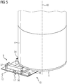
- the tool arrangement 1 is provided to simply pivot the tower 4 from a non-erected position ( figs. 1 - 4 ) to an erected position ( fig. 5 ) and to unload the tower 4 from a transport vehicle and store the tower 4 on a construction site with only little effort ( figs. 11 and 12 ).
- the tower 4 is exemplarily a hollow, tubular and pre-casted tower segment of a tower structure of a wind turbine.
- the tower 4 has a circular cross section and comprises a bottom mounting section 5 on its lower axial end and a top mounting section 6 on its upper axial end.
- the mounting sections 5, 6 are mounting flanges pointing radially inwards and comprising several holes.
- the complete tower structure of the wind turbine consists of several towers 4 standing one above the other, wherein the towers 4 are attached to each other by the mounting sections 5, 6 by screws and nuts or other suitable attachment means.
- the bottom tool device 2 comprises an attachment means 7 consisting of two attachment devices 8.
- the attachment devices 8 are mounted on a first device section 9 of the bottom tool device 2.
- the first device section 9 is removably attachable to the bottom mounting section 5 of the tower 4 by the attachment means 7.
- the first device section 9 is not attached to the bottom mounting section 5 and in fig. 2 the first device section 9 is attached to the bottom mounting section 5.
- the attachment means 7 are moved along a horizontal axis to attach the first device section 9 to the tower 4.
- the second device section 10 of the bottom tool device 2 will be explained in more detail. As it will be described later, in fig. 3 the first device section 9 is standing on the ground carrying the weight of the tower 4. The second device section 10 is also arranged on the ground beneath the first device section 9.
- the first device section 9 and the second device section 10 are attachable to each other by axis forming means 11.
- Fig. 3 shows the device sections 9, 10 not attached to each other and
- fig. 4 shows the device sections 9, 10 attached to each other.
- the axis forming means 11 engage with each other when the device sections 9, 10 are attached to each other and build a pivot axis 12 of the bottom tool device 2.
- the tower 4 when fixed to the bottom tool device 2, can be pivoted around the pivot axis 12, wherein the pivot axis 12 is perpendicular to a longitudinal axis 48 of the tower 4 and parallel to the second device section 10 to the ground where the tower 4 will be erected.
- Rotating the tower 4 around the pivot axis 12 allows for pivoting the tower 4 from the non-erected position ( fig. 4 ) to the erected position ( fig. 5 ).
- the tower 4 only needs to be lifted or hoisted by a crane, e.g. by a rope attached to the top mounting section 6 of the tower 4.
- Another crane securing the tower 4 on the bottom mounting section 5 while erecting the tower is not required, since the bottom tool device 2 provides a safe and secure support of the lower tower end while getting erected.
- the first device section 9 comprises a horizontal main beam 13, wherein the attachment devices 8 are movably mounted on the main beam 13 along a longitudinal axis of the main beam 13.
- Figs. 1 and 2 illustrate the mechanism attaching the attachment devices 8 to the bottom mounting section 5.
- the attachment devices 8 are moved away from each other along the longitudinal axis of the main beam 13 leading the attachment devices 8 to engage behind the bottom mounting section 5.
- the bottom mounting section 5 is clamped between each of the attachment devices 8 and the main beam 13 of the first device section 9. Since, as will be described later in more detail, the tower 4 furthermore rests on support sections 34, a safe and secure fixation, especially during the erecting process, of the tower 4 is ensured.
- the first device section 9 comprises the pins 14 and the second device section 10 comprises the pin supports 15.
- the pins 14 are adapted to be inserted into the U-shaped pin supports 15, wherein the longitudinal axis of the pins 14 are aligned to each other forming the pivot axis 12. Inserting the pins 14 into the pin supports 15 is illustrated by figs. 3 and 4 .
- the tower 4, together with the first device section 9, is lowered to insert the pins 14 into the pin supports 15. Details concerning this lowering will be described later in more detail.
- the second device section 10 comprises a ground plate 16 with several ground spikes 17 protruding from the plate 16.
- the spikes 17 are provided to protect the second device section 10 from slipping on the ground while the tower 4 is erected.
- the tower 4 is lowered (like shown in figs. 3 and 4 ) the weight of the tower 4 leads the ground plate 16 getting pressed towards the ground, leading the spikes 17 getting sticked into the ground.
- the ground can be gravelled.
- the top tool device 3 is a frame-like structure comprising a V-shaped beam arrangement 18 with a first beam 19 and a second beam 20, wherein the longitudinal axes of the beams 19, 20 are perpendicular to each other ( fig. 6 ).
- the first beam 19 comprises an extendable first beam bar 21 and the second beam 20 comprises an extendable second beam bar 22.
- Each attachment means 23 is an attachment device 24 located at the axial front end one of the beam bars 21, 22.
- the attachment devices 24 are clamping devices comprising a first clamping part 25 and a second clamping part 26.
- FIGS 7 and 8 Details of attaching the top tool device 3 to the top mounting section 6 are illustrated in figures 7 and 8 , where an enlarged view of the attachment device 24 of the second beam bar 22 is shown.
- the top tool device 3 is not attached to the top mounting section 6.
- the beam bars 21, 22 are extended to position the top mounting section 6 between the clamping parts 25, 26.
- the top mounting section 6 can be attached to the top tool device 3 by clamping the clamping parts 25, 26. Extending the beam bars 21, 22 and clamping the attachment devices 24 occurs via hydraulic or pneumatic means (not shown).
- the top tool device 3 Due to the right angle between the first beam 19 and the second beam 20, the attachment devices 24 can be clamped to the top mounting section 6 diametrically opposed to each other.
- the top tool device 3 comprises a first hoisting fastener 27 and a second hoisting fastener 28 to connect the top tool device 3 to hoisting means 29, i.e. to ropes of a crane.
- the hoisting fasteners 27, 28 can be loops or hooks.
- the tower 4 After being erected, the tower 4 is hoisted to the position where it has to be mounted by the crane. If the tower 4 is the undermost tower section of the complete tower, the tower 4 has to be hoisted or brought to the foundation where it has to be mounted. Otherwise, the tower 4 has to be hoisted to the (already erected and mounted) tower section, on whose top mounting section the bottom mounting section 5 of the tower 4 will be mounted. However, after the tower 4 has been erected and before it gets hoisted to its designated position, the bottom tool device 2 has to be detached from the bottom mounting section 5 of the tower 4. For this purpose, immediately after the tower 4 has been erected and still hangs on the hoisting means 29 of the crane, staff can detach the attachment means 7. After this, the crane can hoist the tower 4 away, wherein the bottom tool device 2 remains at its position on the ground.
- the top tool device 3 can be detached from the top mounting section 6, e.g. by climbing staff. Next, the top tool device 3 can be hoisted or brought away from the tower 4 by the crane. To avoid the top tool device 3 swinging around the axis provided by the hoisting fasteners 27, 28, respectively, a third hoisting fastener 30 of the top tool device 3 is provided to be connected with another hoisting means 31, e.g. another rope, of the crane.
- another hoisting means 31 e.g. another rope
- the top tool device 3 comprises two support sections 32 attached to a horizontal beam 33 on which the V-shaped beam arrangement 18 is attached.
- the tower 4 rests on the support sections 32 when the tower is in the non-erected position and attached to the top tool device 3.
- the support sections 32 of the top tool device 3 are arranged symmetrically to the symmetry axis of the also symmetric V-shaped beam arrangement 18. Hence, the weight of the tower 4 is not only held by the attachment devices 24 but also by the support sections 32. Additionally or alternatively, a support section can also be provided on the V-shaped beam arrangement 18, especially on its lower edge.
- the bottom tool device 2 also comprises two support sections 34, which are attached to a bar 49 protruding vertically downwards from the main beam 13 (see e.g. fig. 1 ).
- the support sections 34 are positioned symmetrically to a vertical symmetry axis of the bottom tool device 2.
- the support sections 32, 34 are rotatably attached to the respective tool device 2, 3. Hence, the contact area of the support sections 32, 34 automatically adjusts to the diameter of the tower 4 when the tool device 2, 3 gets attached to the respective mounting section 5, 6.
- the tower 4 is loaded on the truck 45.
- the tower 4 is fastened to the truck 45 by attaching it on a trailer of the truck 45 by, e.g. tension belts.
- the first device section 9 of the bottom tool device 2 is attached to the bottom mounting section 5 and the top tool device 3 is attached to the top mounting section 6.
- Fig. 11 shows the situation, where the tool devices 2, 3 are attached to the tower 4, wherein the tower 4 is loaded on the truck 45.
- the first device section 9 of the bottom tool device 2 comprises a lifting means 35 and the top tool device 3 comprises a lifting means 36.
- the lifting means 35 comprises two extendable pillars 37 which can be extended from vertical beams 38 of the first device section 9 of the bottom tool device 2.
- the lifting means 36 also comprises two extendable pillars 39, which are extendable from vertical beams 40 of the top tool device 3.
- the pillars 37, 39 are not extended while the tower 4 is transported to the construction side by the truck 45 (see Fig. 11 ). In this situation, the weight of the tower 4 weighs on the truck 45.
- the pillars 37, 39 of the tool devices 2, 3 are extended towards the ground by hydraulic and pneumatic means. During the extending process, the pillars 37, 39 get in contact with the ground (which should be firm and stable). Preferably all pillars 37, 39 get in touch with the ground at the same time. After this, the pillars 37, 39 are extended further (exemplarily some centimetres or decimetres) so that the weight of the tower 4 does not weigh on the truck 45 anymore, but on the pillars 37, 39. Additionally the tower 4 will be lifted or raised during this process, ideally by the same distance as the pillars 37, 39 are further extended after getting into contact with the ground.
- Fig. 12 shows the tower 4 with the tool devices 2, 3 being attached to the mounting sections 5, 6 and the pillars 37, 39 being extended after the truck 45 is leaving the tower 4.
- Fig. 13 shows the tower 4 after the truck 45 has left the construction site.
- the tool arrangement 1 allows for unloading the tower 4 from the truck 45 without the need of a crane. So far, for unloading the tower 4 even two cranes have been required, wherein each side of the tower 4 has been hoisted by one of the two cranes, the truck 45 has been driven away and the cranes have lowered the tower 4 to store it on supporting feet.
- Supporting feet are often used as supporting means for towers in the non-erected or lying position. Such supporting feet typically comprise a plain contact area adapted to rest on the ground and an arched or two chock-like contact areas adapted to support the tower 4 on its outer wall.
- the tool arrangement 1 can be used to store the tower 4 temporarily on the construction site, being supported by the tool devices 2, 3 (see. fig. 13 ). For this, no further action is needed to store the tower 4 after being unloaded from the truck 45 as described above. Since the tool devices 2, 3 are attached to the tower 4 on its attachment means 5, 6, a contact of the outer wall to the ground or tower feet, leading to an unwanted deformation or scratches of the tower 4, during the storage of the tower 4 is avoided.
- the tower 4 can be erected.
- the second device section 10 of the bottom tool device 2 is located beneath the first device section 9, as shown in fig. 3 .
- Retracting the pillars 37, 39 makes the axis forming means 11 to engage with each other forming the pivot axis 12 (as shown in fig. 4 ).
- the top tool device 3 comprises a power pack 41.
- the power pack 41 comprises an accumulator (not shown) and is freely rotatable about a horizontal axis to be always aligned horizontally, especially during erecting the tower 4.
- the power pack 41 is equipped with weights at its lower side avoiding battery liquid getting spilled.
- the tool arrangement 1 further comprises transportation means 42 with two fork pockets 43.
- the transportation means 42 can be removably attached to the tool devices 2, 3, wherein a telescopic handler 44 can be used to lift the respective tool device 3, 4 to attach it to the tower, which is already loaded on the truck 45.
- Fig. 15 shows three top tool devices 3 which are stacked.
- Each of the top tool devices 3 comprises four storing pillars 46 which are detachably attached to the vertical beams 38.
- the axes of the storing pillars 46 and the vertical beams 38 are rectangular to each other.
- the storing pillars 45 enable the top tool devices 3 to be stacked for, e.g. transportation or storing or the like.
- each storing pillar 46 rests on a respective storing pillar support, which can be a recessed section of the adjacent top tool device 3.
- the tool arrangement 1 further comprises a frame-like connecting piece 47 which is removably attachable to the bottom tool device 2 and to the top tool device 3 on opposite sides of the connecting piece 47.
- the tool devices 2, 3 can be attached to the connecting piece 47 by attaching means like screws, clamping devices or the like (not shown).
Landscapes
- Engineering & Computer Science (AREA)
- Architecture (AREA)
- Civil Engineering (AREA)
- Structural Engineering (AREA)
- Life Sciences & Earth Sciences (AREA)
- Sustainable Development (AREA)
- Sustainable Energy (AREA)
- Chemical & Material Sciences (AREA)
- Combustion & Propulsion (AREA)
- Mechanical Engineering (AREA)
- General Engineering & Computer Science (AREA)
- Conveying And Assembling Of Building Elements In Situ (AREA)
- Cutting Tools, Boring Holders, And Turrets (AREA)
Priority Applications (6)
| Application Number | Priority Date | Filing Date | Title |
|---|---|---|---|
| EP19172753.6A EP3736396A1 (fr) | 2019-05-06 | 2019-05-06 | Agencement d'outil pour faire pivoter une tour ou un segment de tour d'une position non érigée à une position érigée |
| EP20718198.3A EP3942124A1 (fr) | 2019-05-06 | 2020-03-27 | Agencement d'outil servant à faire pivoter une tour ou un segment de tour d'une position non érigée à une position érigée |
| US17/606,805 US11713586B2 (en) | 2019-05-06 | 2020-03-27 | Tool arrangement for pivoting a tower or a tower segment from a non-erected position to an erected position |
| PCT/EP2020/058685 WO2020224868A1 (fr) | 2019-05-06 | 2020-03-27 | Agencement d'outil servant à faire pivoter une tour ou un segment de tour d'une position non érigée à une position érigée |
| BR112021021406A BR112021021406A2 (pt) | 2019-05-06 | 2020-03-27 | Arranjo de ferramenta para girar uma torre ou um segmento de torre de uma posição não erguida para uma posição erguida |
| CN202080033946.1A CN113795642B (zh) | 2019-05-06 | 2020-03-27 | 用于将塔架或塔架段从非竖立位置枢转至竖立位置的工具布置结构 |
Applications Claiming Priority (1)
| Application Number | Priority Date | Filing Date | Title |
|---|---|---|---|
| EP19172753.6A EP3736396A1 (fr) | 2019-05-06 | 2019-05-06 | Agencement d'outil pour faire pivoter une tour ou un segment de tour d'une position non érigée à une position érigée |
Publications (1)
| Publication Number | Publication Date |
|---|---|
| EP3736396A1 true EP3736396A1 (fr) | 2020-11-11 |
Family
ID=66429256
Family Applications (2)
| Application Number | Title | Priority Date | Filing Date |
|---|---|---|---|
| EP19172753.6A Withdrawn EP3736396A1 (fr) | 2019-05-06 | 2019-05-06 | Agencement d'outil pour faire pivoter une tour ou un segment de tour d'une position non érigée à une position érigée |
| EP20718198.3A Pending EP3942124A1 (fr) | 2019-05-06 | 2020-03-27 | Agencement d'outil servant à faire pivoter une tour ou un segment de tour d'une position non érigée à une position érigée |
Family Applications After (1)
| Application Number | Title | Priority Date | Filing Date |
|---|---|---|---|
| EP20718198.3A Pending EP3942124A1 (fr) | 2019-05-06 | 2020-03-27 | Agencement d'outil servant à faire pivoter une tour ou un segment de tour d'une position non érigée à une position érigée |
Country Status (5)
| Country | Link |
|---|---|
| US (1) | US11713586B2 (fr) |
| EP (2) | EP3736396A1 (fr) |
| CN (1) | CN113795642B (fr) |
| BR (1) | BR112021021406A2 (fr) |
| WO (1) | WO2020224868A1 (fr) |
Cited By (1)
| Publication number | Priority date | Publication date | Assignee | Title |
|---|---|---|---|---|
| EP4043721A1 (fr) * | 2021-02-15 | 2022-08-17 | Siemens Gamesa Renewable Energy A/S | Système d'installation et procédé de basculement et d'installation d'une tour de turbine éolienne |
Families Citing this family (1)
| Publication number | Priority date | Publication date | Assignee | Title |
|---|---|---|---|---|
| EP3736442A1 (fr) * | 2019-05-06 | 2020-11-11 | Siemens Gamesa Renewable Energy A/S | Agencement d'outil pour décharger une tour ou d'un segment de tour à partir d'un véhicule de transport et/ou pour le stockage de la tour ou le segment de tour |
Citations (4)
| Publication number | Priority date | Publication date | Assignee | Title |
|---|---|---|---|---|
| US4127199A (en) * | 1977-01-25 | 1978-11-28 | Sparrows Contract Services Limited | Lifting apparatus |
| DE3731931A1 (de) * | 1987-09-23 | 1989-04-06 | Pfleiderer Fa G A | Mast fuer mess- oder beleuchtungszwecke, insbesondere fuer flugbefeuerung |
| EP1873332A1 (fr) * | 2006-06-27 | 2008-01-02 | Siemens Aktiengesellschaft | Outil et procédé pour ériger un segment de tour |
| WO2011134472A1 (fr) * | 2010-04-29 | 2011-11-03 | Vestas Wind Systems A/S | Manœuvre d'une grue sapine destinée à être utilisée dans le montage et l'entretien d'éléments de génératrices d'éolienne |
Family Cites Families (10)
| Publication number | Priority date | Publication date | Assignee | Title |
|---|---|---|---|---|
| US3638375A (en) * | 1970-08-04 | 1972-02-01 | Mikhail Ivanovich Vasiliev | Hoisting equipment and method of use |
| US4079559A (en) | 1976-11-01 | 1978-03-21 | Kim Lighting, Inc. | Hinged base for lighting pole |
| US4451198A (en) * | 1978-07-17 | 1984-05-29 | Sanderson Edward T | Material handling device |
| US20070114799A1 (en) | 2005-11-18 | 2007-05-24 | Andre Riesberg | Systems and methods for damping a displacement of a wind turbine tower |
| FR2918649B1 (fr) * | 2007-07-10 | 2012-02-10 | Transnuclear Inc | Emballage de stockage longue duree a fond amovible. |
| CN101599619B (zh) | 2008-06-06 | 2012-02-29 | 上海市电力公司 | 跨越架立柱的安装装置及其安装方法 |
| IN2014MN01496A (fr) * | 2012-02-01 | 2015-07-03 | Vsl Int Ag | |
| CN104555734A (zh) | 2013-10-15 | 2015-04-29 | 烟台中集来福士海洋工程有限公司 | 一种海工吊机的上立柱翻转装置及方法 |
| CN106744312B (zh) | 2016-12-28 | 2018-11-30 | 新疆金风科技股份有限公司 | 塔筒翻转装置及塔筒的吊装方法 |
| CN109667721B (zh) | 2019-01-02 | 2021-01-29 | 武汉船用机械有限责任公司 | 一种塔筒单元竖立工装 |
-
2019
- 2019-05-06 EP EP19172753.6A patent/EP3736396A1/fr not_active Withdrawn
-
2020
- 2020-03-27 BR BR112021021406A patent/BR112021021406A2/pt unknown
- 2020-03-27 WO PCT/EP2020/058685 patent/WO2020224868A1/fr unknown
- 2020-03-27 US US17/606,805 patent/US11713586B2/en active Active
- 2020-03-27 CN CN202080033946.1A patent/CN113795642B/zh active Active
- 2020-03-27 EP EP20718198.3A patent/EP3942124A1/fr active Pending
Patent Citations (4)
| Publication number | Priority date | Publication date | Assignee | Title |
|---|---|---|---|---|
| US4127199A (en) * | 1977-01-25 | 1978-11-28 | Sparrows Contract Services Limited | Lifting apparatus |
| DE3731931A1 (de) * | 1987-09-23 | 1989-04-06 | Pfleiderer Fa G A | Mast fuer mess- oder beleuchtungszwecke, insbesondere fuer flugbefeuerung |
| EP1873332A1 (fr) * | 2006-06-27 | 2008-01-02 | Siemens Aktiengesellschaft | Outil et procédé pour ériger un segment de tour |
| WO2011134472A1 (fr) * | 2010-04-29 | 2011-11-03 | Vestas Wind Systems A/S | Manœuvre d'une grue sapine destinée à être utilisée dans le montage et l'entretien d'éléments de génératrices d'éolienne |
Cited By (2)
| Publication number | Priority date | Publication date | Assignee | Title |
|---|---|---|---|---|
| EP4043721A1 (fr) * | 2021-02-15 | 2022-08-17 | Siemens Gamesa Renewable Energy A/S | Système d'installation et procédé de basculement et d'installation d'une tour de turbine éolienne |
| CN114941606A (zh) * | 2021-02-15 | 2022-08-26 | 西门子歌美飒可再生能源公司 | 竖立和安装风力涡轮机塔架的安装系统和方法 |
Also Published As
| Publication number | Publication date |
|---|---|
| WO2020224868A1 (fr) | 2020-11-12 |
| BR112021021406A2 (pt) | 2022-02-15 |
| CN113795642B (zh) | 2023-03-28 |
| US20220205269A1 (en) | 2022-06-30 |
| EP3942124A1 (fr) | 2022-01-26 |
| CN113795642A (zh) | 2021-12-14 |
| US11713586B2 (en) | 2023-08-01 |
Similar Documents
| Publication | Publication Date | Title |
|---|---|---|
| US9446932B2 (en) | Pole lifting and setting device | |
| US9266701B2 (en) | Enhanced stability crane and methods of use | |
| US8640340B2 (en) | Offshore wind turbine installation | |
| US11713586B2 (en) | Tool arrangement for pivoting a tower or a tower segment from a non-erected position to an erected position | |
| US11971013B2 (en) | Tool arrangement for unloading a tower or a tower segment from a transportation vehicle and/or for storing the tower or the tower segment | |
| US10968895B1 (en) | Wind turbine shipping method | |
| US6048012A (en) | Understructure lifting beam | |
| US10202262B2 (en) | Method of operating a crane, and crane | |
| US8932000B2 (en) | Methods for positioning a large load into a transport position and for positioning a large load into a storage position, trailer and/or lorry | |
| KR102228841B1 (ko) | 4축 전동식 갠트리 크레인 조립체 | |
| AU2013219246A1 (en) | Hopper Handling Kit and Apparatus | |
| EP3632833A1 (fr) | Ensemble de levage pour éolienne | |
| US7634890B2 (en) | Tower segment erection tool and method of erecting a tower segment | |
| NL2011985C2 (en) | Saddle and hook system. | |
| EP1801318A1 (fr) | Véhicule pour le transport de matériaux sur l'extérieur de bâtiments | |
| US7017963B1 (en) | Counter weighted lifting beam | |
| RU202754U1 (ru) | Грузоподъемный механизм для спуска и подъема кассет огнепреградителей на резервуарах вертикальных стальных | |
| CN110402317B (zh) | 用于处理、储存和运输的系统和方法 | |
| JP3242775B2 (ja) | 竪型容器の据付方法 | |
| JP2002037589A (ja) | 地下埋設設備の吊上装置、及び該設備の吊上作業方法 | |
| AU2004293121B2 (en) | Lifting apparatus | |
| JP3278771B2 (ja) | 資材の運搬建込装置 |
Legal Events
| Date | Code | Title | Description |
|---|---|---|---|
| PUAI | Public reference made under article 153(3) epc to a published international application that has entered the european phase |
Free format text: ORIGINAL CODE: 0009012 |
|
| STAA | Information on the status of an ep patent application or granted ep patent |
Free format text: STATUS: THE APPLICATION HAS BEEN PUBLISHED |
|
| AK | Designated contracting states |
Kind code of ref document: A1 Designated state(s): AL AT BE BG CH CY CZ DE DK EE ES FI FR GB GR HR HU IE IS IT LI LT LU LV MC MK MT NL NO PL PT RO RS SE SI SK SM TR |
|
| AX | Request for extension of the european patent |
Extension state: BA ME |
|
| STAA | Information on the status of an ep patent application or granted ep patent |
Free format text: STATUS: THE APPLICATION IS DEEMED TO BE WITHDRAWN |
|
| 18D | Application deemed to be withdrawn |
Effective date: 20210512 |