EP3736091B1 - Isolator system - Google Patents
Isolator system Download PDFInfo
- Publication number
- EP3736091B1 EP3736091B1 EP18898181.5A EP18898181A EP3736091B1 EP 3736091 B1 EP3736091 B1 EP 3736091B1 EP 18898181 A EP18898181 A EP 18898181A EP 3736091 B1 EP3736091 B1 EP 3736091B1
- Authority
- EP
- European Patent Office
- Prior art keywords
- gas
- glove box
- flow rate
- exhaust
- operation space
- Prior art date
- Legal status (The legal status is an assumption and is not a legal conclusion. Google has not performed a legal analysis and makes no representation as to the accuracy of the status listed.)
- Active
Links
Images


Classifications
-
- B—PERFORMING OPERATIONS; TRANSPORTING
- B25—HAND TOOLS; PORTABLE POWER-DRIVEN TOOLS; MANIPULATORS
- B25J—MANIPULATORS; CHAMBERS PROVIDED WITH MANIPULATION DEVICES
- B25J21/00—Chambers provided with manipulation devices
- B25J21/02—Glove-boxes, i.e. chambers in which manipulations are performed by the human hands in gloves built into the chamber walls; Gloves therefor
-
- B—PERFORMING OPERATIONS; TRANSPORTING
- B01—PHYSICAL OR CHEMICAL PROCESSES OR APPARATUS IN GENERAL
- B01L—CHEMICAL OR PHYSICAL LABORATORY APPARATUS FOR GENERAL USE
- B01L1/00—Enclosures; Chambers
- B01L1/02—Air-pressure chambers; Air-locks therefor
-
- G—PHYSICS
- G21—NUCLEAR PHYSICS; NUCLEAR ENGINEERING
- G21F—PROTECTION AGAINST X-RADIATION, GAMMA RADIATION, CORPUSCULAR RADIATION OR PARTICLE BOMBARDMENT; TREATING RADIOACTIVELY CONTAMINATED MATERIAL; DECONTAMINATION ARRANGEMENTS THEREFOR
- G21F7/00—Shielded cells or rooms
- G21F7/04—Shielded glove-boxes
- G21F7/041—Glove-box atmosphere, temperature or pressure control devices
-
- C—CHEMISTRY; METALLURGY
- C12—BIOCHEMISTRY; BEER; SPIRITS; WINE; VINEGAR; MICROBIOLOGY; ENZYMOLOGY; MUTATION OR GENETIC ENGINEERING
- C12M—APPARATUS FOR ENZYMOLOGY OR MICROBIOLOGY; APPARATUS FOR CULTURING MICROORGANISMS FOR PRODUCING BIOMASS, FOR GROWING CELLS OR FOR OBTAINING FERMENTATION OR METABOLIC PRODUCTS, i.e. BIOREACTORS OR FERMENTERS
- C12M37/00—Means for sterilizing, maintaining sterile conditions or avoiding chemical or biological contamination
Definitions
- the present invention relates to a technique of exhausting a gas in a glove box which is provided in an isolator system.
- a glove box (hereinafter, which is also referred to as a "GB") that is capable of performing the handling of a substance in an operation space which is isolated from outside (internal operation), in order to prevent the substance from leaking outside when handling the substance affecting the human body or the environment.
- a glove which is inserted into the operation space is connected to a front surface of the GB, and an operator inserts the arm into the glove to perform an internal operation in the operation space.
- the operation space (the inside of the GB) is maintained at a pressure (negative pressure) which is lower than an outside pressure.
- Patent Documents 1 and 2 describe a technique of controlling forced exhaust means (Patent Document 1) for forcibly exhausting a gas in the GB or an exhaust valve (Patent Document 2) provided in an exhaust system, based on a result of detecting a differential pressure between inside and outside the GB.
- Patent Document 3 A conventional isolator system according to the preamble portion of claim 1 of the present application is disclosed in Patent Document 3.
- Patent Document 4 A further conventional isolator system is disclosed in Patent Document 4.
- a method for controlling the exhaust of a gas from the GB based on the result of detecting the differential pressure between inside and outside the GB is used as the method for maintaining the inside of the GB at a negative pressure.
- Patent Document 1 pressure sensors 41 and 42, a first opening and closing valve 13, and a second opening and closing valve 22, and Patent Document 2: a differential pressure gauge 16, a negative pressure gauge 18, a gas supply valve 22, an exhaust valve 26, and a bypass valve 32
- Patent Document 2 a differential pressure gauge 16, a negative pressure gauge 18, a gas supply valve 22, an exhaust valve 26, and a bypass valve 32
- control in a case where a large damage opening is formed in the GB due to the falling off of the glove or the like, since the pressure difference between inside and outside the GB decreases rapidly, control is performed to greatly increase the amount of exhaust from the GB within a short period of time in order to secure a target differential pressure.
- the invention is made under the above-described background, and provides an isolator system that is capable of stably maintaining a pressure in an operation space at a negative pressure with a simple configuration.
- This isolator system includes, in particular:
- the isolator system may have the following characteristics.
- the isolator system further includes a partition member which partitions an inside of the glove box into the operation space and a buffer space where the exhaust port is formed, and in which a communication port is formed to communicate the operation space and the buffer space with each other, and a buffer side gas supply unit that includes the intake port and supplies a buffer gas to the buffer space, wherein the buffer side gas supply unit includes a supply stop mechanism which, when a damage opening is formed due to the operation portion falling off from the glove box which forms the operation space, stops supplying the buffer gas such that the gas passing from the operation room, in which the glove box is located, into the operation space through the damage opening flows in at the predetermined speed or greater, said predetermined speed being set in advance.
- the supply stop mechanism stops supplying the buffer gas.
- an exhaust flow rate of a gas from an exhaust port of a glove box is regulated to an exhaust flow rate where a differential pressure which is set in advance can be formed in a differential pressure forming portion provided in an intake port of the glove box, with a simple configuration, it is possible to maintain the internal pressure of the glove box at a negative pressure.
- a configuration example of an isolator system including a glove box (GB) 11 for inputting a raw material into a reaction vessel 4 which proceeds with a reaction for producing, for example, an intermediate product or a final product will be described with reference to Figs. 1 and 2 .
- the supply amount of a gas (for example, air) from outside to an operation room 3 provided with the reaction vessel 4 is restricted for the purpose of maintaining a differential pressure between the operation room 3 and an adjacent area, or the like.
- the GB 11 has, for example, a structure where a panel portion (not illustrated) made of glass is provided in a front surface of a housing made of metal, and the GB 11 forms an operation space 10 which is isolated from an outside space.
- a glove 14 is airtightly attached to the front surface of the GB 11 which is arranged to face an operator.
- the glove 14 corresponds to an operation portion for performing an internal operation in the operation space 10.
- a side surface of the operation space 10 may include, for example, a bag import to which a carry in and carry out bag for carrying in and out a substance from the GB 11 is attached (the carry in and carry out bag and the bag import are not illustrated).
- a bottom surface of the GB 11 is provided with an input pipe 15 which is configured to be connectable to a receiving pipe 41 provided in the reaction vessel 4, and through which a raw material is input thereinto.
- the input pipe 15 is provided to penetrate a bottom plate of the GB 11.
- a lower end portion of the input pipe 15 is provided with a flange which can be fastened to the receiving pipe 41.
- an upper end portion of the input pipe 15 is inserted into the operation space 10.
- an upper surface of the GB 11 is provided with an intake port 12 for taking a gas (for example, air) in the operation room 3 into the operation space 10, and an exhaust port 13 for exhausting a gas (for example, air) in the operation space 10.
- a gas for example, air
- the intake port 12 is provided with a filter 121 which forms a differential pressure forming portion in this embodiment.
- the differential pressure forming portion (the filter 121) has the function of forming a differential pressure which is set in advance between the inside (the operation space 10) and the outside (the operation room 3) of the GB 11.
- the filter 121 provided in the intake port 12 it is possible to select a particle filter such as a high efficiency particulate air (HEPA) filter or a mesh filter with coarser meshes in order to answer the purpose such as preventing dust or foreign matter from infiltrating into the operation space 10 in addition to the function as the above-described differential pressure forming portion.
- a particle filter such as a high efficiency particulate air (HEPA) filter or a mesh filter with coarser meshes
- the exhaust port 13 is provided with a filter 131 for preventing the leak of a substance being handled (in this example, a raw material for producing an intermediate product or a final product) in the operation space 10.
- An exhaust pipe 21 is connected to an outlet side of the exhaust port 13.
- the exhaust pipe 21 penetrates a ceiling portion 31 of the operation room 3 to extend outside the operation room 3 and be connected to an exhaust mechanism (not illustrated) including an exhaust fan and the like.
- the exhaust pipe 21 which leads out to an upper surface side of the operation room 3 is provided with a flow rate regulation mechanism 22 for regulating the exhaust flow rate of the gas which is exhausted from the exhaust port 13 to the exhaust pipe 21.
- the flow rate regulation mechanism 22 includes a damper capable of regulating the opening angle and the like.
- a controller 222 regulates the opening angle based on a result of measuring the exhaust flow rate with a flow meter 221 provided in the exhaust pipe 21, such that an actual exhaust flow rate approaches a target exhaust flow rate (target flow rate) which is set in advance.
- the target flow rate for the exhaust flow rate of the gas which is regulated by the flow rate regulation mechanism 22 is set from the following three viewpoints.
- the target flow rate is set such that the differential pressure which is set in advance is formed in the filter 121 which is the differential pressure forming portion provided in the intake port 12.
- the differential pressure is formed in the filter 121; and thereby, it is possible to maintain a negative pressure state where the pressure in the operation space 10 is lower than the pressure in the operation room 3.
- the exhaust flow rate where a differential pressure which corresponds to the pressure difference between the pressure of the outside (the operation room 3) of the GB 11 and the pressure in the operation space 10 can be formed in the filter 121 is set as the target flow rate.
- the target flow rate is set such that a differential pressure of 100 Pa (initial value before the differential pressure increases due to the collection of particles or the like) within a range of 50 to 200 Pa is formed as an example of the differential pressure which is formed in the filter 121.
- a differential pressure of 100 Pa initial value before the differential pressure increases due to the collection of particles or the like
- a range of 50 to 200 Pa is formed as an example of the differential pressure which is formed in the filter 121.
- the target flow rate is set such that when the GB 11 is damaged, the leak of a substance being handled can be prevented.
- the GB 11 is a housing made of metal
- the glove 14 attached to the front surface of the GB 11 falls off from an attachment port thereof, or the carry in and carry out bag is removed from the bag import provided in a side surface of the GB 11, and thus, a relatively large opening (damage opening 110) is formed.
- the target flow rate may be set such that even in a case where the damage opening 110 described above is formed, an airflow which flows from the operation room 3 into the operation space 10 at a predetermined lowest air speed or greater is formed by continuously exhausting the gas inside the damage opening 110 through the exhaust port 13.
- the lowest air speed of the gas which flows in through the damage opening 110 it is possible to provide an air speed of 0.5 m/s within a range of 0.4 to 1.0 m/s. It is possible to specify the target flow rate by multiplying the lowest air speed by the opening area of the damage opening 110 (the attachment port for the glove 14 or the bag import).
- the exhaust flow rate is set based on assuming the event where the damage opening 110 which is the largest may occur such as the falling off of the glove 14 or the bag import, even in a case where the event occurs such as the occurrence of the damage opening 110 which is smaller, the flow speed of the gas flowing into the damage opening 110 can be maintained at the predetermined lowest air speed or greater.
- a third viewpoint is that a pressure increase in the operation space 10 which is involved by performing an internal operation has to be prevented.
- the largest target flow rate is adopted and the exhaust flow rate is regulated; and thereby, it is possible to attain the effects such as maintaining a negative pressure in the operation space 10, preventing the outflow of the gas when the damage opening 110 is formed, and maintaining a negative pressure in the operation space 10 when an internal operation which involves a change in the internal volume is performed.
- the target flow rate is set in order to satisfy all of the viewpoints.
- the target flow rate may be set in order to satisfy at least the first viewpoint (forming the differential pressure for maintaining a negative pressure in the operation space 10) depending on the function required for the GB 11.
- the input pipe 15 is connected to the receiving pipe 41 of the reaction vessel 4 into which a raw material is input or the like, and thus, the operation space 10 which is isolated from outside is formed ( Fig. 1 ) .
- the exhaust air volume may be regulated in response to the entering and exiting of the gas.
- an operator performs a necessary internal operation using the operation portion such as the glove 14 or the bag import, and in addition thereto, instruments and the like provided in the operation space 10.
- the exhaust flow rate of the gas from the exhaust port 13 is set to an exhaust flow rate which is obtained by adding an exhaust flow rate, which is equivalent to the change speed of the internal volume when the internal volume decreases, to the already described exhaust flow rate for maintaining a negative pressure in the operation space 10; and thereby, it is possible to maintain a negative pressure state in the operation space 10.
- the exhaust flow rate is, for example, an exhaust flow rate where when the pressure of a secondary side of the flow rate regulation mechanism 22 is maintained constant, the pressure difference between the operation room 3 and the secondary side of the flow rate regulation mechanism 22 and a pressure loss which occurs in the filter 121 or 131, the exhaust pipe 21, or the flow rate regulation mechanism 22 balance out each other.
- the flow rate regulation mechanism 22 prevents an increase in the exhaust flow rate which is involved by a pressure increase in the operation space 10, and performs the regulation of the flow rate in order to maintain the exhaust flow rate constant.
- the flow speed of the gas which flows in through the damage opening 110 can be maintained at the predetermined lowest air speed (for example, 0.5 m/s), and the outflow of a substance which is being handled in the operation space 10 can be prevented.
- the isolator system according to this embodiment provides the following effects. Since the exhaust flow rate of the gas from the exhaust port 13 of the GB 11 is regulated to the exhaust flow rate where the differential pressure which is set in advance can be formed in the differential pressure forming portion (the filter 121) provided in the intake port 12 of the GB 11, with a simple configuration, the internal pressure of the GB 11 can be maintained at a negative pressure.
- the embodiment is not limited to a case where the differential pressure forming portion provided in the intake port 12 includes only the filter 121 which is described with reference to Figs. 1 and 2 .
- a differential pressure regulation valve 122 which is a damper or the like may be provided.
- the configuration where the installation of the filter 121 is omitted and only the differential pressure regulation valve 122 is provided in the intake port 12 may be adopted (not illustrated).
- the exhaust pipe 21 extends outside the operation room 3.
- the configuration where the exhaust pipe 21 is connected to an exhaust fan 23 provided in the operation room 3, and the gas exhausted from the exhaust port 13 returns to the operation room 3 may be adopted.
- the GB 11 of this example is applicable to a case where in maintaining an atmosphere of an inert gas such as a nitrogen gas in the operation space 10, the amount of consumption of the inert gas is reduced, or the like.
- the inside of the GB 11 is partitioned into the operation space 10 and a buffer space 10a by a partition member 18, and the operation space 10 and the buffer space 10a communicate with each other through a communication port 181.
- the partition member 18 is provided with a filter 182, and a substance which is being handled in the operation space 10 is not allowed to enter the buffer space 10a.
- the partition member 18 is provided with the glove 14 or the input pipe 15 which is already described. Instead of the intake port 12, an operation space side gas supply unit 17 for supplying an inert gas (in this example, a nitrogen gas), which is an operation space gas, to the operation space 10 is provided in the partition member 18.
- an inert gas in this example, a nitrogen gas
- the operation space side gas supply unit 17 includes a nitrogen gas supply unit 171 including a nitrogen storage unit or a flow rate regulation unit, and a nitrogen gas supply pipe 173 which is provided with an opening and closing valve 172. A distal end portion of the nitrogen gas supply pipe 173 is inserted into the operation space 10.
- the intake port 12 which is provided with, for example, the filter 121 that is the differential pressure forming portion, is provided in the buffer space 10a. Furthermore, a supply stop mechanism 161 which is an opening and closing damper or the like is provided in the intake port 12, and is capable of stopping taking the gas in through the intake port 12.
- the intake port 12 and the supply stop mechanism 161 are equivalent to a buffer side gas supply unit 16 which supplies a buffer gas (in this example, air) to the buffer space 10a.
- a buffer side gas supply unit 16 which supplies a buffer gas (in this example, air) to the buffer space 10a.
- the supply stop mechanism 161 is instructed by a controller 162 to perform an opening and closing operation based on a result of measuring a differential pressure between inside and outside the operation space 10 with a differential pressure measurement unit 163.
- the controller 162 controls the operation of the supply stop mechanism 161 such that when the differential pressure in the operation space 10 with respect to the operation room 3 reaches a negative pressure with a magnitude set in advance, the supply stop mechanism 161 is closed to stop the gas (buffer gas) from being taken into the buffer space 10a.
- the controller 162 does not necessarily have an opening angle regulation function.
- the taking in of the buffer gas may be stopped using a manual damper which regulates the pressure, and a lid where only closing is allowed.
- the configuration where the opening angle of a damper is manually regulated and only the closing operation of the damper is automatically performed may be adopted.
- the target flow rate for the exhaust flow rate from the exhaust port 13 is set from, for example, the above-described three viewpoints (forming a negative pressure in the operation space 10, ensuring the flow speed of the gas which flows into the operation space 10 when the damage opening 110 is formed, and maintaining a negative pressure in the operation space 10 when an internal operation which involves a change in internal volume is performed).
- the flow rate of the operation space gas (nitrogen gas) supplied from the operation space side gas supply unit 17 is set at a flow rate where a pressure loss occurring when the buffer gas (air) taken in from the intake port 12 passes through the filter (differential pressure forming portion) 121 provided in the buffer side gas supply unit 16 becomes larger than a pressure loss occurring when the operation space gas passes through the filter 182 provided in the partition member 18.
- the pressure in the operation space 10 and the buffer space 10a can be maintained at a negative pressure with respect to the operation room 3 by the differential pressure which occurs in the filter 121 of the intake port 12 by the above-described setting of the flow rate. Then, in a case where the supply amount of the operation space gas which is an inert gas is restricted to a small amount, the pressure in the operation space 10 approaches the pressure of the buffer space 10a; and thereby, it is possible to maintain a negative pressure in the operation space 10 while filling the operation space 10 with the inert gas.
- the input pipe 15 is connected to the receiving pipe 41 of the reaction vessel 4, and thus, the operation space 10 which is isolated from outside is formed ( Fig. 5 ). Subsequently, an inert gas is introduced at a flow rate which is set in advance from the operation space side gas supply unit 17, and thus, the inside of the operation space 10 becomes an atmosphere of the inert gas.
- each gas Since the flow rate of each gas is regulated such that the differential pressure occurring when the gas (buffer gas) taken in from the intake port 12 passes through the filter 121 becomes larger than the differential pressure occurring when the inert gas (operation space gas) in the operation space 10 passes through the filter 182 of the communication port 181, the operation space 10 is maintained in a negative pressure state with respect to the operation room 3.
- This embodiment is the same as the first embodiment in that at the time, even in a case where the internal operation involves a change in the internal volume of the operation space 10, the exhaust flow rate of the gas from the exhaust port 13 is set to an exhaust flow rate which is obtained by adding an exhaust flow rate, which is equivalent to the change speed of the internal volume when the internal volume decreases, to the already described exhaust flow rate for maintaining a negative pressure in the operation space 10 (including the exhaust flow rate which corresponds to the supply flow rate of the inert gas); and thereby, it is possible to maintain a negative pressure state in the operation space 10.
- the flow rate regulation mechanism 22 prevents an increase in the exhaust flow rate which is involved by a pressure increase in the operation space 10, and performs the regulation of the flow rate in order to maintain the exhaust flow rate constant.
- the flow speed of the gas which flows in through the damage opening 110 can be maintained at the predetermined lowest air speed (for example, 0.5 m/s), and the outflow of a substance which is being handled in the operation space 10 can be prevented.
- the filter 182 since the inside of the operation space 10 is maintained at a negative pressure by introducing the buffer gas into the buffer space 10a, it is preferable to select the filter 182 with as small pressure loss as possible which is provided in the communication port 181 between the operation space 10 and the buffer space 10a. From this viewpoint, it is not indispensable to provide the filter 182 in the communication port 181. In a case where the substance which is being handled in the operation space 10 does not need to be prevented from entering the buffer space 10a, only the communication port 181 may be provided.
- the operation space side gas supply unit 17 it is not indispensable to provide the operation space side gas supply unit 17 and supply the operation space gas.
- the configuration where the gas is not introduced into the operation space 10 may be adopted.
- the plurality of reaction vessels 4 are arranged side by side in a state where an upper portion side of each of the reaction vessels 4 including the receiving pipes 41 described above is inserted into the operation room 3.
- a pair of two travel paths 51 having a rail shape are arranged on the ceiling portion 31 of the operation room 3, which is positioned above the reaction vessels 4, to extend along an arrangement direction of the reaction vessels 4.
- a traveling body 52 including, for example, wheels and an axle is movably arranged on the travel paths 51.
- Suspension support portions 53 for supporting the GB 11 in a suspended manner are attached to the axle of the traveling body 52.
- the GB 11 is capable of freely moving in the operation room 3 along the travel paths 51 ( Fig. 7 ).
- the exhaust pipe 21 which exhausts the gas from the GB 11 is divided into an indoor side exhaust pipe portion 211 attached to the GB 11, and an outdoor side exhaust pipe portion 212 which is arranged in a fixed manner in a state where the outdoor side exhaust pipe portion 212 extends on an upper surface side of the ceiling portion 31.
- the indoor side exhaust pipe portion 211 of the GB 11 is capable of moving in the operation room 3.
- a plurality of the outdoor side exhaust pipe portions 212 are arranged in a fixed manner on a ceiling portion side of the operation room 3 to each correspond to the arrangement position of each of the reaction vessels 4. Then, the flow rate regulation mechanism 22, the flow meter 221, or the controller 222 which is already described is provided in each of the outdoor side exhaust pipe portions 212 (only the flow rate regulation mechanism 22 is illustrated in Fig. 7 ).
- connection port portion 213 is arranged on the ceiling portion of the operation room 3, and a distal end portion of the indoor side exhaust pipe portion 211 is detachable to the connection port portion 213.
- the GB 11 moves toward the reaction vessel 4 which is a target where an internal operation is performed ( Fig. 8 ), the input pipe 15 is connected to the reaction vessel 4, and a distal end portion of the indoor side exhaust pipe portion 211 is connected to the outdoor side exhaust pipe portion 212 ( Figs. 7 and 9 ); and thereby, it is possible to form the isolator system which is described with reference to Figs. 1 and 2 , Figs. 5 and 6 , or the like.
- the exhaust mechanism which is provided downstream of the outdoor side exhaust pipe portions 212 is common thereto, it is not necessary to provide a plurality of electric motors such as the exhaust fans, and it is not necessary to switch between the electric motors, which is a merit.
Landscapes
- Engineering & Computer Science (AREA)
- Robotics (AREA)
- Mechanical Engineering (AREA)
- Physics & Mathematics (AREA)
- General Engineering & Computer Science (AREA)
- High Energy & Nuclear Physics (AREA)
- Health & Medical Sciences (AREA)
- Clinical Laboratory Science (AREA)
- Chemical & Material Sciences (AREA)
- Chemical Kinetics & Catalysis (AREA)
- Devices For Use In Laboratory Experiments (AREA)
- Manipulator (AREA)
Description
- The present invention relates to a technique of exhausting a gas in a glove box which is provided in an isolator system.
- There is known a glove box (hereinafter, which is also referred to as a "GB") that is capable of performing the handling of a substance in an operation space which is isolated from outside (internal operation), in order to prevent the substance from leaking outside when handling the substance affecting the human body or the environment.
- For example, a glove which is inserted into the operation space is connected to a front surface of the GB, and an operator inserts the arm into the glove to perform an internal operation in the operation space.
- At the time, in order to prevent the leak of a substance being handled, the operation space (the inside of the GB) is maintained at a pressure (negative pressure) which is lower than an outside pressure.
- As a method for maintaining the inside of the GB at a negative pressure, Patent Documents 1 and 2 describe a technique of controlling forced exhaust means (Patent Document 1) for forcibly exhausting a gas in the GB or an exhaust valve (Patent Document 2) provided in an exhaust system, based on a result of detecting a differential pressure between inside and outside the GB.
- A conventional isolator system according to the preamble portion of claim 1 of the present application is disclosed in
Patent Document 3. A further conventional isolator system is disclosed inPatent Document 4. -
- Patent Document 1:
JP-A-2013-86183 - Patent Document 2:
Japanese Patent No. 2,537,689 - Patent Document 3: US Patent Publication No.
US 5 730 777 A - Patent Document 4: Japanese Patent Publication No.
JP 2015 226970 A - As described above, generally, a method for controlling the exhaust of a gas from the GB based on the result of detecting the differential pressure between inside and outside the GB is used as the method for maintaining the inside of the GB at a negative pressure.
- However, in order to realize this control based on the detection of the differential pressure, it is necessary to detect the differential pressure between inside and outside the GB with a high sensitivity, and provide a plurality of pressure regulation valves with good responsiveness (Patent Document 1:
pressure sensors 41 and 42, a first opening andclosing valve 13, and a second opening andclosing valve 22, and Patent Document 2: adifferential pressure gauge 16, anegative pressure gauge 18, agas supply valve 22, an exhaust valve 26, and a bypass valve 32) . For this reason, a pressure control mechanism of the GB becomes large in scale, and the above-described requirement also becomes a factor which increases the cost of the apparatus. - In addition, in the above-described control method, in a case where a large damage opening is formed in the GB due to the falling off of the glove or the like, since the pressure difference between inside and outside the GB decreases rapidly, control is performed to greatly increase the amount of exhaust from the GB within a short period of time in order to secure a target differential pressure.
- As a result, a pressure change occurs, so that the inside of an operation room where the GB is arranged enters a rapidly reduced pressure atmosphere, and it is not possible to properly maintain the differential pressure between rooms with respect to an area adjacent to the operation room, which is a concern.
- The invention is made under the above-described background, and provides an isolator system that is capable of stably maintaining a pressure in an operation space at a negative pressure with a simple configuration.
- According to the invention, there is provided an isolator system as defined in claim 1. This isolator system includes, in particular:
- a glove box that includes an operation portion including a glove for performing an internal operation, and forms an operation space which is isolated from outside,
- an intake port for taking a gas into the glove box,
- an exhaust port connected to an exhaust pipe for exhausting the gas in the glove box, and
- a flow rate regulation mechanism that regulates an exhaust flow rate of the gas, which is exhausted from the exhaust port to the exhaust pipe, to an exhaust flow rate where a differential pressure which is set in advance can be formed between the operation space and the outside of the glove box by a differential pressure forming portion provided in the intake port.
- The isolator system may have the following characteristics.
- (a) The exhaust flow rate is set such that in a case where the operation portion falls off from the glove box, the gas which passes from an operation room, in which the glove box is located, into the operation space through a damage opening formed in the glove box flows in at a predetermined speed or greater, said predetermined speed being set in advance. Alternatively, the exhaust flow rate is set at an exhaust flow rate which is obtained by adding an exhaust flow rate, which is equivalent to a change speed of an internal volume of the glove box when the internal volume decreases, to the exhaust flow rate where the differential pressure which is set in advance can be formed.
- (b) The differential pressure forming portion is a filter. Alternatively, the differential pressure forming portion is a differential pressure regulation valve.
- (c) The glove box is provided in the operation room into which a supply amount of the gas from outside is restricted, the intake port takes the gas in from the operation room, and the exhaust pipe exhausts the gas in the glove box outside the operation room. Alternatively, the glove box is provided in an operation room, the exhaust pipe exhausts the gas in the glove box outside the operation room, and the flow rate regulation mechanism is provided outside the operation room.
- According to the invention, the isolator system further includes a partition member which partitions an inside of the glove box into the operation space and a buffer space where the exhaust port is formed, and in which a communication port is formed to communicate the operation space and the buffer space with each other, and a buffer side gas supply unit that includes the intake port and supplies a buffer gas to the buffer space, wherein the buffer side gas supply unit includes a supply stop mechanism which, when a damage opening is formed due to the operation portion falling off from the glove box which forms the operation space, stops supplying the buffer gas such that the gas passing from the operation room, in which the glove box is located, into the operation space through the damage opening flows in at the predetermined speed or greater, said predetermined speed being set in advance.
- Advantageously,
in a case where the damage opening is formed, when a differential pressure which is measured by a differential pressure measurement unit provided in order to measure the differential pressure between the operation space and the outside of the glove box reaches a negative pressure with a magnitude set in advance, the supply stop mechanism stops supplying the buffer gas. - (g) The isolator system may further include a travel path that extends along an arrangement direction of a plurality of reaction vessels and is arranged above the reaction vessels in an operation room where the reaction vessels connectable to the glove box are arranged, a traveling body that is provided to be movable along the travel path in a state where the traveling body is supported on the travel path, and a suspension support portion for supporting the glove box in a suspended manner from the traveling body.
- (h) In (g), the exhaust pipe is connected to the exhaust port, and the exhaust pipe includes an indoor side exhaust pipe portion that moves along the travel path as the glove box moves, and outdoor side exhaust pipe portions that are provided at a plurality of locations to correspond to the plurality of reaction vessels, and extend on an upper surface side of a ceiling portion of the operation room from connection port portions which are provided in the ceiling portion and are configured to be detachable from a distal end portion of the indoor side exhaust pipe portion in a state where the glove box is connected to the reaction vessel.
- According to the invention, since an exhaust flow rate of a gas from an exhaust port of a glove box is regulated to an exhaust flow rate where a differential pressure which is set in advance can be formed in a differential pressure forming portion provided in an intake port of the glove box, with a simple configuration, it is possible to maintain the internal pressure of the glove box at a negative pressure.
-
-
Fig. 1 is a configuration diagram of an isolator system according to a first embodiment, which is not in accordance with the invention. -
Fig. 2 is a diagram of the operation of the GB when a glove falls off. -
Fig. 3 is a configuration diagram of a GB where a differential pressure regulation valve is provided on an intake port side. -
Fig. 4 is a configuration diagram of an isolator system which exhausts a gas in an operation room. -
Fig. 5 is a configuration diagram of an isolator system according to a second embodiment, which is in accordance with the invention. -
Fig. 6 is a diagram of the operation of a GB according to the second embodiment when a glove falls off. -
Fig. 7 is a configuration diagram of a GB which is configured to be detachable from a plurality of reaction vessels. -
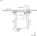
Fig. 8 is a diagram showing the GB before being connected to the reaction vessel. -
Fig. 9 is a diagram showing the GB after being connected to the reaction vessel. - Hereinafter, as a first embodiment which is not in accordance with the invention, a configuration example of an isolator system including a glove box (GB) 11 for inputting a raw material into a
reaction vessel 4 which proceeds with a reaction for producing, for example, an intermediate product or a final product will be described with reference toFigs. 1 and2 . The supply amount of a gas (for example, air) from outside to anoperation room 3 provided with thereaction vessel 4 is restricted for the purpose of maintaining a differential pressure between theoperation room 3 and an adjacent area, or the like. - The GB 11 has, for example, a structure where a panel portion (not illustrated) made of glass is provided in a front surface of a housing made of metal, and the
GB 11 forms anoperation space 10 which is isolated from an outside space. - A
glove 14 is airtightly attached to the front surface of theGB 11 which is arranged to face an operator. Theglove 14 corresponds to an operation portion for performing an internal operation in theoperation space 10. - In addition to the
glove 14, as another example of the operation portion provided in theGB 11, a side surface of theoperation space 10 may include, for example, a bag import to which a carry in and carry out bag for carrying in and out a substance from theGB 11 is attached (the carry in and carry out bag and the bag import are not illustrated). - A bottom surface of the
GB 11 is provided with aninput pipe 15 which is configured to be connectable to a receivingpipe 41 provided in thereaction vessel 4, and through which a raw material is input thereinto. Theinput pipe 15 is provided to penetrate a bottom plate of theGB 11. A lower end portion of theinput pipe 15 is provided with a flange which can be fastened to the receivingpipe 41. On the other hand, an upper end portion of theinput pipe 15 is inserted into theoperation space 10. - For example, an upper surface of the
GB 11 is provided with anintake port 12 for taking a gas (for example, air) in theoperation room 3 into theoperation space 10, and anexhaust port 13 for exhausting a gas (for example, air) in theoperation space 10. - The
intake port 12 is provided with afilter 121 which forms a differential pressure forming portion in this embodiment. The differential pressure forming portion (the filter 121) has the function of forming a differential pressure which is set in advance between the inside (the operation space 10) and the outside (the operation room 3) of theGB 11. - As the
filter 121 provided in theintake port 12, it is possible to select a particle filter such as a high efficiency particulate air (HEPA) filter or a mesh filter with coarser meshes in order to answer the purpose such as preventing dust or foreign matter from infiltrating into theoperation space 10 in addition to the function as the above-described differential pressure forming portion. - In addition, the
exhaust port 13 is provided with afilter 131 for preventing the leak of a substance being handled (in this example, a raw material for producing an intermediate product or a final product) in theoperation space 10. Anexhaust pipe 21 is connected to an outlet side of theexhaust port 13. - For example, the
exhaust pipe 21 penetrates aceiling portion 31 of theoperation room 3 to extend outside theoperation room 3 and be connected to an exhaust mechanism (not illustrated) including an exhaust fan and the like. - The
exhaust pipe 21 which leads out to an upper surface side of theoperation room 3 is provided with a flowrate regulation mechanism 22 for regulating the exhaust flow rate of the gas which is exhausted from theexhaust port 13 to theexhaust pipe 21. The flowrate regulation mechanism 22 includes a damper capable of regulating the opening angle and the like. Acontroller 222 regulates the opening angle based on a result of measuring the exhaust flow rate with aflow meter 221 provided in theexhaust pipe 21, such that an actual exhaust flow rate approaches a target exhaust flow rate (target flow rate) which is set in advance. - In the isolator system with the above-described configuration, the target flow rate for the exhaust flow rate of the gas which is regulated by the flow
rate regulation mechanism 22 is set from the following three viewpoints. - From a first viewpoint, the target flow rate is set such that the differential pressure which is set in advance is formed in the
filter 121 which is the differential pressure forming portion provided in theintake port 12. - When a pressure change along the flow of the gas which is taken into the GB 11 (the operation space 10) and then is exhausted to the
exhaust pipe 21 through theexhaust port 13 is observed, the pressure of the gas becomes the highest in theoperation room 3, and becomes the lowest in an inflow portion of the exhaust mechanism (not illustrated) which is positioned at a downstream end of theexhaust pipe 21. - At the time, in a case where the
intake port 12 is provided with thefilter 121 which is the differential pressure forming portion, the differential pressure is formed in thefilter 121; and thereby, it is possible to maintain a negative pressure state where the pressure in theoperation space 10 is lower than the pressure in theoperation room 3. - Therefore, based on a set pressure value which has to be maintained in the
operation space 10 while an internal operation is performed or the like, the exhaust flow rate where a differential pressure which corresponds to the pressure difference between the pressure of the outside (the operation room 3) of theGB 11 and the pressure in theoperation space 10 can be formed in thefilter 121 is set as the target flow rate. - As an example, it is possible to provide a case where the target flow rate is set such that a differential pressure of 100 Pa (initial value before the differential pressure increases due to the collection of particles or the like) within a range of 50 to 200 Pa is formed as an example of the differential pressure which is formed in the
filter 121. Incidentally, since the target flow rate is changed depending on the volume of theoperation space 10, the opening area of theintake port 12, and the like, it is difficult to generally specify the target flow rate. - From a second viewpoint, the target flow rate is set such that when the
GB 11 is damaged, the leak of a substance being handled can be prevented. - For example, in a case where the
GB 11 is a housing made of metal, there is a possibility that theglove 14 attached to the front surface of theGB 11 falls off from an attachment port thereof, or the carry in and carry out bag is removed from the bag import provided in a side surface of theGB 11, and thus, a relatively large opening (damage opening 110) is formed. - In a case where the
damage opening 110 is formed, there is almost no differential pressure between theoperation room 3 and inside of theoperation space 10, and for example, the flow of a fine-particle substance being handled, or the flow of a gas generated from the substance being handled, both of which flow from the inside of theoperation space 10 to theoperation room 3, is formed, which is also a concern. - Therefore, the target flow rate may be set such that even in a case where the
damage opening 110 described above is formed, an airflow which flows from theoperation room 3 into theoperation space 10 at a predetermined lowest air speed or greater is formed by continuously exhausting the gas inside thedamage opening 110 through theexhaust port 13. - As an example of the lowest air speed of the gas which flows in through the
damage opening 110, it is possible to provide an air speed of 0.5 m/s within a range of 0.4 to 1.0 m/s. It is possible to specify the target flow rate by multiplying the lowest air speed by the opening area of the damage opening 110 (the attachment port for theglove 14 or the bag import). - Incidentally, in a case where the exhaust flow rate is set based on assuming the event where the
damage opening 110 which is the largest may occur such as the falling off of theglove 14 or the bag import, even in a case where the event occurs such as the occurrence of thedamage opening 110 which is smaller, the flow speed of the gas flowing into thedamage opening 110 can be maintained at the predetermined lowest air speed or greater. - A third viewpoint is that a pressure increase in the
operation space 10 which is involved by performing an internal operation has to be prevented. The internal operation in theGB 11, for example, the case of inserting theglove 14 which leads outside into theoperation space 10 through the attachment port, the case of raising a cylinder-shaped elevation mechanism (not illustrated) which is provided in theoperation space 10, or the like, involves a change in the internal volume of theoperation space 10. - At the time, in a case where the change in the internal volume occurs at a speed exceeding the exhaust flow rate in the
operation space 10, the pressure in theoperation space 10 increases to become a positive pressure, which is a concern. - Therefore, the internal operation which involves a change in the internal volume of the
operation space 10 is assumed, and an exhaust flow rate larger than the change speed of the internal volume is set as the target flow rate; and thereby, it is possible to prevent a pressure increase in theoperation space 10 caused by an internal operation. - In a case where the target flow rates which are obtained from the above-described three viewpoints differ from each other, the largest target flow rate is adopted and the exhaust flow rate is regulated; and thereby, it is possible to attain the effects such as maintaining a negative pressure in the
operation space 10, preventing the outflow of the gas when thedamage opening 110 is formed, and maintaining a negative pressure in theoperation space 10 when an internal operation which involves a change in the internal volume is performed. - Incidentally, in the
GB 11, it is not an indispensable requirement that the target flow rate is set in order to satisfy all of the viewpoints. The target flow rate may be set in order to satisfy at least the first viewpoint (forming the differential pressure for maintaining a negative pressure in the operation space 10) depending on the function required for theGB 11. - The operation of the isolator system with the above-described configuration will be described.
- In performing an internal operation, while the exhaust flow rate is regulated by the flow
rate regulation mechanism 22, theinput pipe 15 is connected to the receivingpipe 41 of thereaction vessel 4 into which a raw material is input or the like, and thus, theoperation space 10 which is isolated from outside is formed (Fig. 1 ) . At the time, in a case where the gas enters and exits from thereaction vessel 4 through the receivingpipe 41, the exhaust air volume may be regulated in response to the entering and exiting of the gas. As theoperation space 10 is formed, the gas in theoperation room 3 is taken into theoperation space 10 through theintake port 12, and the differential pressure which is set in advance is formed in thefilter 121, and thus, the inside of theoperation space 10 is maintained in a negative pressure state with respect to theoperation room 3. - Thereafter, an operator performs a necessary internal operation using the operation portion such as the
glove 14 or the bag import, and in addition thereto, instruments and the like provided in theoperation space 10. - At the time, even in a case where the internal operation involves a change in the internal volume of the
operation space 10, the exhaust flow rate of the gas from theexhaust port 13 is set to an exhaust flow rate which is obtained by adding an exhaust flow rate, which is equivalent to the change speed of the internal volume when the internal volume decreases, to the already described exhaust flow rate for maintaining a negative pressure in theoperation space 10; and thereby, it is possible to maintain a negative pressure state in theoperation space 10. - Here, the exhaust flow rate is, for example, an exhaust flow rate where when the pressure of a secondary side of the flow
rate regulation mechanism 22 is maintained constant, the pressure difference between theoperation room 3 and the secondary side of the flowrate regulation mechanism 22 and a pressure loss which occurs in thefilter exhaust pipe 21, or the flowrate regulation mechanism 22 balance out each other. - Subsequently, as illustrated in
Fig. 2 , it is assumed that as the operation portion such as theglove 14 falls off, thedamage opening 110 is formed. In this case, the gas flows in through thedamage opening 110 more easily than through theintake port 12 where a large differential pressure is formed, the pressure in theoperation space 10 increases, and almost no pressure loss occurs in thefilter 121. For this reason, in a case where any regulation is not performed, the exhaust flow rate increases such that the pressure loss in thefilter 121 before thedamage opening 110 is formed and the pressure loss occurring in thefilter 131, theexhaust pipe 21, or the flowrate regulation mechanism 22 balance out each other. - However, in the isolator system of this example, the flow
rate regulation mechanism 22 prevents an increase in the exhaust flow rate which is involved by a pressure increase in theoperation space 10, and performs the regulation of the flow rate in order to maintain the exhaust flow rate constant. - As a result, the flow speed of the gas which flows in through the
damage opening 110 can be maintained at the predetermined lowest air speed (for example, 0.5 m/s), and the outflow of a substance which is being handled in theoperation space 10 can be prevented. - Then, at the time, in the
GB 11 of this example, since the exhaust flow rate from theexhaust port 13 is maintained constant before and after thedamage opening 110 is formed, a large pressure change does not occur in theoperation room 3. - The isolator system according to this embodiment provides the following effects. Since the exhaust flow rate of the gas from the
exhaust port 13 of theGB 11 is regulated to the exhaust flow rate where the differential pressure which is set in advance can be formed in the differential pressure forming portion (the filter 121) provided in theintake port 12 of theGB 11, with a simple configuration, the internal pressure of theGB 11 can be maintained at a negative pressure. - Here, the embodiment is not limited to a case where the differential pressure forming portion provided in the
intake port 12 includes only thefilter 121 which is described with reference toFigs. 1 and2 . For example, as illustrated inFig. 3 , in addition to thefilter 121, a differentialpressure regulation valve 122 which is a damper or the like may be provided. In addition, the configuration where the installation of thefilter 121 is omitted and only the differentialpressure regulation valve 122 is provided in theintake port 12 may be adopted (not illustrated). - In addition, as illustrated in
Figs. 1 and2 , in a case where the flowrate regulation mechanism 22 is provided in theexhaust pipe 21 which leads out outside theoperation room 3, since a maintenance worker completes maintenance without entering theoperation room 3, the maintenance of the flowrate regulation mechanism 22 is facilitated. - However, it is not an indispensable requirement that the
exhaust pipe 21 extends outside theoperation room 3. For example, as illustrated inFig. 4 , the configuration where theexhaust pipe 21 is connected to anexhaust fan 23 provided in theoperation room 3, and the gas exhausted from theexhaust port 13 returns to theoperation room 3 may be adopted. - Subsequently, an isolator system according to a second embodiment will be described with reference to
Figs. 5 and6 . This embodiment is in accordance with the invention. In each drawing which will be described hereinafter, the reference signs which are common toFigs. 1 to 4 are assigned to the configuration elements which are common to theGB 11 described with reference to these drawings. - The
GB 11 of this example is applicable to a case where in maintaining an atmosphere of an inert gas such as a nitrogen gas in theoperation space 10, the amount of consumption of the inert gas is reduced, or the like. - The inside of the
GB 11 is partitioned into theoperation space 10 and a buffer space 10a by apartition member 18, and theoperation space 10 and the buffer space 10a communicate with each other through acommunication port 181. In this example, thepartition member 18 is provided with afilter 182, and a substance which is being handled in theoperation space 10 is not allowed to enter the buffer space 10a. - The
partition member 18 is provided with theglove 14 or theinput pipe 15 which is already described. Instead of theintake port 12, an operation space sidegas supply unit 17 for supplying an inert gas (in this example, a nitrogen gas), which is an operation space gas, to theoperation space 10 is provided in thepartition member 18. - For example, the operation space side
gas supply unit 17 includes a nitrogengas supply unit 171 including a nitrogen storage unit or a flow rate regulation unit, and a nitrogengas supply pipe 173 which is provided with an opening and closingvalve 172. A distal end portion of the nitrogengas supply pipe 173 is inserted into theoperation space 10. - Then, in the
GB 11 of this example, theintake port 12, which is provided with, for example, thefilter 121 that is the differential pressure forming portion, is provided in the buffer space 10a. Furthermore, asupply stop mechanism 161 which is an opening and closing damper or the like is provided in theintake port 12, and is capable of stopping taking the gas in through theintake port 12. - The
intake port 12 and thesupply stop mechanism 161 are equivalent to a buffer sidegas supply unit 16 which supplies a buffer gas (in this example, air) to the buffer space 10a. - The
supply stop mechanism 161 is instructed by acontroller 162 to perform an opening and closing operation based on a result of measuring a differential pressure between inside and outside theoperation space 10 with a differentialpressure measurement unit 163. Thecontroller 162 controls the operation of thesupply stop mechanism 161 such that when the differential pressure in theoperation space 10 with respect to theoperation room 3 reaches a negative pressure with a magnitude set in advance, thesupply stop mechanism 161 is closed to stop the gas (buffer gas) from being taken into the buffer space 10a. - Incidentally, the
controller 162 does not necessarily have an opening angle regulation function. In addition, the taking in of the buffer gas may be stopped using a manual damper which regulates the pressure, and a lid where only closing is allowed. On the contrary, the configuration where the opening angle of a damper is manually regulated and only the closing operation of the damper is automatically performed may be adopted. - Here, similar to the
GB 11 according to the first embodiment which is described with reference toFigs. 1 and2 , the target flow rate for the exhaust flow rate from theexhaust port 13 is set from, for example, the above-described three viewpoints (forming a negative pressure in theoperation space 10, ensuring the flow speed of the gas which flows into theoperation space 10 when thedamage opening 110 is formed, and maintaining a negative pressure in theoperation space 10 when an internal operation which involves a change in internal volume is performed). - Furthermore, in the
GB 11 of this example, the flow rate of the operation space gas (nitrogen gas) supplied from the operation space sidegas supply unit 17 is set at a flow rate where a pressure loss occurring when the buffer gas (air) taken in from theintake port 12 passes through the filter (differential pressure forming portion) 121 provided in the buffer sidegas supply unit 16 becomes larger than a pressure loss occurring when the operation space gas passes through thefilter 182 provided in thepartition member 18. - The pressure in the
operation space 10 and the buffer space 10a can be maintained at a negative pressure with respect to theoperation room 3 by the differential pressure which occurs in thefilter 121 of theintake port 12 by the above-described setting of the flow rate. Then, in a case where the supply amount of the operation space gas which is an inert gas is restricted to a small amount, the pressure in theoperation space 10 approaches the pressure of the buffer space 10a; and thereby, it is possible to maintain a negative pressure in theoperation space 10 while filling theoperation space 10 with the inert gas. - Subsequently, an operation of an isolator system according to the second embodiment will be described.
- In performing an internal operation, while the exhaust flow rate is regulated by the flow
rate regulation mechanism 22, theinput pipe 15 is connected to the receivingpipe 41 of thereaction vessel 4, and thus, theoperation space 10 which is isolated from outside is formed (Fig. 5 ). Subsequently, an inert gas is introduced at a flow rate which is set in advance from the operation space sidegas supply unit 17, and thus, the inside of theoperation space 10 becomes an atmosphere of the inert gas. - Since the flow rate of each gas is regulated such that the differential pressure occurring when the gas (buffer gas) taken in from the
intake port 12 passes through thefilter 121 becomes larger than the differential pressure occurring when the inert gas (operation space gas) in theoperation space 10 passes through thefilter 182 of thecommunication port 181, theoperation space 10 is maintained in a negative pressure state with respect to theoperation room 3. - Thereafter, an operator performs a necessary internal operation. This embodiment is the same as the first embodiment in that at the time, even in a case where the internal operation involves a change in the internal volume of the
operation space 10, the exhaust flow rate of the gas from theexhaust port 13 is set to an exhaust flow rate which is obtained by adding an exhaust flow rate, which is equivalent to the change speed of the internal volume when the internal volume decreases, to the already described exhaust flow rate for maintaining a negative pressure in the operation space 10 (including the exhaust flow rate which corresponds to the supply flow rate of the inert gas); and thereby, it is possible to maintain a negative pressure state in theoperation space 10. - Subsequently, as illustrated in
Fig. 6 , it can be considered that as the operation portion such as theglove 14 falls off, thedamage opening 110 is formed. In this case, when the differentialpressure measurement unit 163 detects a decrease in the differential pressure between theoperation room 3 and theoperation space 10, and the differential pressure reaches a negative pressure with a magnitude set in advance, an operation is performed to close thesupply stop mechanism 161 which is provided close to theintake port 12. - As a result, the taking in of the buffer gas from the
intake port 12 is stopped, and the gas which flows into theGB 11 is only the gas which flows into theoperation space 10 through thedamage opening 110. Subsequently, since the pressure in theoperation space 10 and the buffer space 10a increases, in a case where any regulation is not performed, the exhaust flow rate increases so that the pressure loss of thefilter 121 which disappears by the formation of thedamage opening 110 can be compensated by thefilter 131, theexhaust pipe 21, or the flowrate regulation mechanism 22. - However, in the isolator system of this example, the flow
rate regulation mechanism 22 prevents an increase in the exhaust flow rate which is involved by a pressure increase in theoperation space 10, and performs the regulation of the flow rate in order to maintain the exhaust flow rate constant. - As a result, the flow speed of the gas which flows in through the
damage opening 110 can be maintained at the predetermined lowest air speed (for example, 0.5 m/s), and the outflow of a substance which is being handled in theoperation space 10 can be prevented. - Then, also in the
GB 11 of this example, since the exhaust flow rate from theexhaust port 13 is maintained constant before and after thedamage opening 110 is formed, a large pressure change does not occur in theoperation room 3. - As described above, in the
GB 11 of this example, since the inside of theoperation space 10 is maintained at a negative pressure by introducing the buffer gas into the buffer space 10a, it is preferable to select thefilter 182 with as small pressure loss as possible which is provided in thecommunication port 181 between theoperation space 10 and the buffer space 10a. From this viewpoint, it is not indispensable to provide thefilter 182 in thecommunication port 181. In a case where the substance which is being handled in theoperation space 10 does not need to be prevented from entering the buffer space 10a, only thecommunication port 181 may be provided. - In addition, it is not indispensable to provide the operation space side
gas supply unit 17 and supply the operation space gas. The configuration where the gas is not introduced into theoperation space 10 may be adopted. - Subsequently, an example of an isolator system where the
GB 11 is configured to be movable between a plurality of thereaction vessels 4 will be described with reference toFigs. 7 and8 . - In the example illustrated in
Fig. 7 , the plurality ofreaction vessels 4 are arranged side by side in a state where an upper portion side of each of thereaction vessels 4 including the receivingpipes 41 described above is inserted into theoperation room 3. - For example, a pair of two
travel paths 51 having a rail shape are arranged on theceiling portion 31 of theoperation room 3, which is positioned above thereaction vessels 4, to extend along an arrangement direction of thereaction vessels 4. As illustrated inFig. 8 , a travelingbody 52 including, for example, wheels and an axle is movably arranged on thetravel paths 51.Suspension support portions 53 for supporting theGB 11 in a suspended manner are attached to the axle of the travelingbody 52. - With the above-described configuration, the
GB 11 is capable of freely moving in theoperation room 3 along the travel paths 51 (Fig. 7 ). - In addition, as illustrated in
Fig. 8 , theexhaust pipe 21 which exhausts the gas from theGB 11 is divided into an indoor sideexhaust pipe portion 211 attached to theGB 11, and an outdoor sideexhaust pipe portion 212 which is arranged in a fixed manner in a state where the outdoor sideexhaust pipe portion 212 extends on an upper surface side of theceiling portion 31. - As a result, together with the
GB 11 which is supported on thesuspension support portions 53, the indoor sideexhaust pipe portion 211 of theGB 11 is capable of moving in theoperation room 3. - On the other hand, as illustrated in
Fig. 7 , a plurality of the outdoor sideexhaust pipe portions 212 are arranged in a fixed manner on a ceiling portion side of theoperation room 3 to each correspond to the arrangement position of each of thereaction vessels 4. Then, the flowrate regulation mechanism 22, theflow meter 221, or thecontroller 222 which is already described is provided in each of the outdoor side exhaust pipe portions 212 (only the flowrate regulation mechanism 22 is illustrated inFig. 7 ). - Furthermore, for each of the outdoor side
exhaust pipe portions 212, aconnection port portion 213 is arranged on the ceiling portion of theoperation room 3, and a distal end portion of the indoor sideexhaust pipe portion 211 is detachable to theconnection port portion 213. - With the above-described configuration, the
GB 11 moves toward thereaction vessel 4 which is a target where an internal operation is performed (Fig. 8 ), theinput pipe 15 is connected to thereaction vessel 4, and a distal end portion of the indoor sideexhaust pipe portion 211 is connected to the outdoor side exhaust pipe portion 212 (Figs. 7 and9 ); and thereby, it is possible to form the isolator system which is described with reference toFigs. 1 and2 ,Figs. 5 and6 , or the like. - At the time, since the plurality of outdoor side
exhaust pipe portions 212 including the flowrate regulation mechanisms 22 are arranged in a fixed manner on theoperation room 3 to correspond to the plurality ofreaction vessels 4, it is not necessary to install a control mechanism of the flowrate regulation mechanism 22 which is configured to be movable together with theGB 11, and the like, thereby contributing to the weight reduction and the cost saving of theGB 11. - In addition, since, for example, the exhaust mechanism which is provided downstream of the outdoor side
exhaust pipe portions 212 is common thereto, it is not necessary to provide a plurality of electric motors such as the exhaust fans, and it is not necessary to switch between the electric motors, which is a merit. -
- 10
- Operation space
- 10a
- Buffer space
- 11
- Glove box (GB)
- 110
- Damage opening
- 12
- Intake port
- 121
- Filter
- 122
- Differential pressure regulation valve
- 13
- Exhaust port
- 14
- Glove
- 22
- Flow rate regulation mechanism
- 3
- Operation room
- 4
- Reaction vessel
- 41
- Receiving pipe
Claims (3)
- An isolator system comprising:a glove box (11) that includes an operation portion (14) including a glove for performing an internal operation, and forms an operation space (10) which is isolated from outside;an intake port (12) for taking a gas into the glove box (11);an exhaust port (13) connected to an exhaust pipe (21) for exhausting the gas in the glove box (11);a flow rate regulation mechanism (22) that regulates an exhaust flow rate of the gas, which is exhausted from the exhaust port (13) to the exhaust pipe (21), to an exhaust flow rate where a differential pressure which is set in advance can be formed between the operation space (10) and the outside of the glove box (11) by a differential pressure forming portion (121) provided in the intake port (12), characterized bya partition member (18) which partitions an inside of the glove box (11) into the operation space (10) and a buffer space (10a) where the exhaust port (13) is formed, and in which a communication port (181) is formed to communicate the operation space (10) and the buffer space (10a) with each other; anda buffer side gas supply unit (16) that includes the intake port (12) and supplies a buffer gas to the buffer space (10a),wherein the buffer side gas supply unit (16) includes a supply stop mechanism (161) which, when a damage opening (110) is formed due to the operation portion (14) falling off from the glove box (11) which forms the operation space (10), stops supplying the buffer gas such that the gas passing from an operation room (3), in which the glove box (11) is located, into the operation space (10) through the damage opening (110) flows in at a predetermined speed or greater, said predetermined speed being set in advance.
- The isolator system according to claim 1,
wherein in a case where the damage opening (110) is formed, when a differential pressure which is measured by a differential pressure measurement unit (163) provided in order to measure the differential pressure between the operation space (10) and the outside of the glove box (11) reaches a negative pressure with a magnitude set in advance, the supply stop mechanism (161) stops supplying the buffer gas. - The isolator system according to claim 1, further comprising:a travel path (51) that extends along an arrangement direction of a plurality of reaction vessels (4) and is arranged above the reaction vessels (4) in an operation room where the reaction vessels (4) connectable to the glove box (11) are arranged;a traveling body (52) that is provided to be movable along the travel path (51) in a state where the traveling body (52) is supported on the travel path (51); anda suspension support portion (53) for supporting the glove box (11) in a suspended manner from the traveling body (52),wherein the exhaust pipe (21) is connected to the exhaust port (13), and the exhaust pipe (21) includes an indoor side exhaust pipe portion (211) that moves along the travel path (51) as the glove box (11) moves, and outdoor side exhaust pipe portions (212) that are provided at a plurality of locations to correspond to the plurality of reaction vessels (4), and extend on an upper surface side of a ceiling portion of the operation room from connection port portions (213) which are provided in the ceiling portion and are configured to be detachable from a distal end portion of the indoor side exhaust pipe portion in a state where the glove box (11) is connected to the reaction vessel (4).
Priority Applications (1)
| Application Number | Priority Date | Filing Date | Title |
|---|---|---|---|
| EP21205180.9A EP3964289B1 (en) | 2018-01-05 | 2018-01-05 | Isolator system |
Applications Claiming Priority (1)
| Application Number | Priority Date | Filing Date | Title |
|---|---|---|---|
| PCT/JP2018/000105 WO2019135283A1 (en) | 2018-01-05 | 2018-01-05 | Isolator system |
Related Child Applications (2)
| Application Number | Title | Priority Date | Filing Date |
|---|---|---|---|
| EP21205180.9A Division-Into EP3964289B1 (en) | 2018-01-05 | 2018-01-05 | Isolator system |
| EP21205180.9A Division EP3964289B1 (en) | 2018-01-05 | 2018-01-05 | Isolator system |
Publications (4)
| Publication Number | Publication Date |
|---|---|
| EP3736091A1 EP3736091A1 (en) | 2020-11-11 |
| EP3736091A4 EP3736091A4 (en) | 2021-04-28 |
| EP3736091C0 EP3736091C0 (en) | 2024-03-06 |
| EP3736091B1 true EP3736091B1 (en) | 2024-03-06 |
Family
ID=65270594
Family Applications (2)
| Application Number | Title | Priority Date | Filing Date |
|---|---|---|---|
| EP18898181.5A Active EP3736091B1 (en) | 2018-01-05 | 2018-01-05 | Isolator system |
| EP21205180.9A Active EP3964289B1 (en) | 2018-01-05 | 2018-01-05 | Isolator system |
Family Applications After (1)
| Application Number | Title | Priority Date | Filing Date |
|---|---|---|---|
| EP21205180.9A Active EP3964289B1 (en) | 2018-01-05 | 2018-01-05 | Isolator system |
Country Status (4)
| Country | Link |
|---|---|
| EP (2) | EP3736091B1 (en) |
| JP (1) | JP6463569B1 (en) |
| SG (1) | SG11202002150QA (en) |
| WO (1) | WO2019135283A1 (en) |
Families Citing this family (6)
| Publication number | Priority date | Publication date | Assignee | Title |
|---|---|---|---|---|
| EP3736091B1 (en) | 2018-01-05 | 2024-03-06 | JGC Japan Corporation | Isolator system |
| CN110450195A (en) * | 2019-09-06 | 2019-11-15 | 威格气体纯化科技(苏州)股份有限公司 | Pressure chamber and seal box with it |
| CN111113493B (en) * | 2020-01-08 | 2025-01-24 | 长沙米淇仪器设备有限公司 | A vacuum operation box for a robotic arm |
| CN114225974B (en) * | 2022-01-18 | 2024-11-19 | 东莞市升微机电设备科技有限公司 | Clean anaerobic chamber |
| CN114939445B (en) * | 2022-03-29 | 2023-12-22 | 合肥通用机械研究院有限公司 | Large vacuum degree change test device and test method using same |
| CN116196721A (en) * | 2023-03-31 | 2023-06-02 | 世源科技工程有限公司 | Dry-type adsorption device |
Family Cites Families (14)
| Publication number | Priority date | Publication date | Assignee | Title |
|---|---|---|---|---|
| JPS5781338U (en) * | 1980-11-07 | 1982-05-19 | ||
| JPS60113079A (en) * | 1983-11-24 | 1985-06-19 | Hitachi Plant Eng & Constr Co Ltd | Negative pressure chamber control equipment |
| JP2537689B2 (en) | 1990-02-22 | 1996-09-25 | 動力炉・核燃料開発事業団 | How to adjust negative pressure and air volume of glove box |
| DK85093D0 (en) * | 1993-07-16 | 1993-07-16 | Landsforeningen Til Kraeftens | METHOD AND APPARATUS FOR PERFORMING OPERATIONS |
| JPH09168992A (en) * | 1995-12-19 | 1997-06-30 | Toshiba Corp | Glove box |
| JP2002228242A (en) * | 2001-02-06 | 2002-08-14 | Hitachi Plant Eng & Constr Co Ltd | Room pressure control method and device |
| AT412264B (en) * | 2002-09-16 | 2004-12-27 | Konstantin Technologies Gmbh | METHOD FOR FULLY FILLING THE GLOVE BOX WITH A GAS AND GLOVE BOX |
| JP2013086183A (en) | 2011-10-13 | 2013-05-13 | Als Technology Co Ltd | Pressure regulating device for glove box |
| JP5588574B1 (en) * | 2014-06-03 | 2014-09-10 | 日揮株式会社 | Isolator system and reaction equipment |
| WO2016183513A1 (en) * | 2015-05-13 | 2016-11-17 | Biospherix Ltd. | Transportable conditioned cell culture enclosure |
| JP6546463B2 (en) * | 2015-06-25 | 2019-07-17 | ヤマト科学株式会社 | Equipment containment device |
| JP6542609B2 (en) * | 2015-08-19 | 2019-07-10 | ヤマト科学株式会社 | Equipment containment device |
| JP6622069B2 (en) * | 2015-11-27 | 2019-12-18 | 株式会社エアレックス | Apparatus having a shielded working room and method of using the same |
| EP3736091B1 (en) | 2018-01-05 | 2024-03-06 | JGC Japan Corporation | Isolator system |
-
2018
- 2018-01-05 EP EP18898181.5A patent/EP3736091B1/en active Active
- 2018-01-05 EP EP21205180.9A patent/EP3964289B1/en active Active
- 2018-01-05 WO PCT/JP2018/000105 patent/WO2019135283A1/en not_active Ceased
- 2018-01-05 SG SG11202002150QA patent/SG11202002150QA/en unknown
- 2018-01-05 JP JP2018552093A patent/JP6463569B1/en active Active
Also Published As
| Publication number | Publication date |
|---|---|
| SG11202002150QA (en) | 2020-07-29 |
| EP3736091C0 (en) | 2024-03-06 |
| WO2019135283A1 (en) | 2019-07-11 |
| JPWO2019135283A1 (en) | 2020-01-16 |
| EP3736091A1 (en) | 2020-11-11 |
| JP6463569B1 (en) | 2019-02-06 |
| EP3964289B1 (en) | 2023-09-20 |
| EP3964289A1 (en) | 2022-03-09 |
| EP3736091A4 (en) | 2021-04-28 |
Similar Documents
| Publication | Publication Date | Title |
|---|---|---|
| EP3964289B1 (en) | Isolator system | |
| CN112429188B (en) | Laboratory for controlling positive air pressure and negative air pressure states of ship cabin | |
| KR101171478B1 (en) | Pressure control with coarse and fine adjustment | |
| KR101574682B1 (en) | Fume hood system for laboratory with indoor suction and exhaust | |
| CN101368833B (en) | Testing bench used for detecting air leakage of automobile air conditioner ventiduct | |
| KR20200012175A (en) | Air conditioning system of negative pressure type special facility | |
| NL2023680B1 (en) | Air sampler device for particle concentration sensor | |
| JP2019100588A (en) | Control method of heat exchange type ventilation fan | |
| CN107774653A (en) | System and method for controlling the pollutant in the isolating device of laboratory | |
| JP6278532B2 (en) | Weighing system | |
| JP2005326093A (en) | Simple bioclean room | |
| KR101903549B1 (en) | Energy Saving System using Control of Exhaust Air Amount and Controlling Air Inflow Rate of Inflow Air Speed Control of Multi - Fume Hood | |
| CN113614456B (en) | Drying chamber and control method thereof | |
| JP5486439B2 (en) | Room pressure control system | |
| KR102348591B1 (en) | Air volume control system for fan filter unit | |
| JP5035043B2 (en) | Cell culture facility | |
| JPH02293554A (en) | Clean room system | |
| JPH02192537A (en) | Indoor absolute pressure controller device | |
| CN219103205U (en) | Dust removal air conditioning system with air pressure detection | |
| CN202578041U (en) | Negative pressure weighing room | |
| FI12412U1 (en) | Ventilation system | |
| CN107917488A (en) | A kind of ultra-precision machine tool environment temperature control system | |
| JPH083861Y2 (en) | Exhaust duct outside air amount control device | |
| JP2021008998A (en) | Air conditioner and air conditioning installation | |
| CN112162511A (en) | Laboratory ventilation control system based on thing networking |
Legal Events
| Date | Code | Title | Description |
|---|---|---|---|
| STAA | Information on the status of an ep patent application or granted ep patent |
Free format text: STATUS: THE INTERNATIONAL PUBLICATION HAS BEEN MADE |
|
| PUAI | Public reference made under article 153(3) epc to a published international application that has entered the european phase |
Free format text: ORIGINAL CODE: 0009012 |
|
| STAA | Information on the status of an ep patent application or granted ep patent |
Free format text: STATUS: REQUEST FOR EXAMINATION WAS MADE |
|
| 17P | Request for examination filed |
Effective date: 20200313 |
|
| AK | Designated contracting states |
Kind code of ref document: A1 Designated state(s): AL AT BE BG CH CY CZ DE DK EE ES FI FR GB GR HR HU IE IS IT LI LT LU LV MC MK MT NL NO PL PT RO RS SE SI SK SM TR |
|
| AX | Request for extension of the european patent |
Extension state: BA ME |
|
| RIC1 | Information provided on ipc code assigned before grant |
Ipc: B25J 21/02 20060101AFI20201201BHEP |
|
| DAV | Request for validation of the european patent (deleted) | ||
| DAX | Request for extension of the european patent (deleted) | ||
| A4 | Supplementary search report drawn up and despatched |
Effective date: 20210330 |
|
| RIC1 | Information provided on ipc code assigned before grant |
Ipc: B25J 21/02 20060101AFI20210324BHEP |
|
| STAA | Information on the status of an ep patent application or granted ep patent |
Free format text: STATUS: EXAMINATION IS IN PROGRESS |
|
| 17Q | First examination report despatched |
Effective date: 20230124 |
|
| GRAP | Despatch of communication of intention to grant a patent |
Free format text: ORIGINAL CODE: EPIDOSNIGR1 |
|
| STAA | Information on the status of an ep patent application or granted ep patent |
Free format text: STATUS: GRANT OF PATENT IS INTENDED |
|
| INTG | Intention to grant announced |
Effective date: 20230802 |
|
| GRAS | Grant fee paid |
Free format text: ORIGINAL CODE: EPIDOSNIGR3 |
|
| GRAA | (expected) grant |
Free format text: ORIGINAL CODE: 0009210 |
|
| STAA | Information on the status of an ep patent application or granted ep patent |
Free format text: STATUS: THE PATENT HAS BEEN GRANTED |
|
| AK | Designated contracting states |
Kind code of ref document: B1 Designated state(s): AL AT BE BG CH CY CZ DE DK EE ES FI FR GB GR HR HU IE IS IT LI LT LU LV MC MK MT NL NO PL PT RO RS SE SI SK SM TR |
|
| REG | Reference to a national code |
Ref country code: GB Ref legal event code: FG4D |
|
| REG | Reference to a national code |
Ref country code: CH Ref legal event code: EP |
|
| REG | Reference to a national code |
Ref country code: DE Ref legal event code: R096 Ref document number: 602018066406 Country of ref document: DE |
|
| REG | Reference to a national code |
Ref country code: IE Ref legal event code: FG4D |
|
| U01 | Request for unitary effect filed |
Effective date: 20240308 |
|
| U07 | Unitary effect registered |
Designated state(s): AT BE BG DE DK EE FI FR IT LT LU LV MT NL PT SE SI Effective date: 20240315 |
|
| PG25 | Lapsed in a contracting state [announced via postgrant information from national office to epo] |
Ref country code: GR Free format text: LAPSE BECAUSE OF FAILURE TO SUBMIT A TRANSLATION OF THE DESCRIPTION OR TO PAY THE FEE WITHIN THE PRESCRIBED TIME-LIMIT Effective date: 20240607 |
|
| PG25 | Lapsed in a contracting state [announced via postgrant information from national office to epo] |
Ref country code: RS Free format text: LAPSE BECAUSE OF FAILURE TO SUBMIT A TRANSLATION OF THE DESCRIPTION OR TO PAY THE FEE WITHIN THE PRESCRIBED TIME-LIMIT Effective date: 20240606 Ref country code: HR Free format text: LAPSE BECAUSE OF FAILURE TO SUBMIT A TRANSLATION OF THE DESCRIPTION OR TO PAY THE FEE WITHIN THE PRESCRIBED TIME-LIMIT Effective date: 20240306 |
|
| PG25 | Lapsed in a contracting state [announced via postgrant information from national office to epo] |
Ref country code: ES Free format text: LAPSE BECAUSE OF FAILURE TO SUBMIT A TRANSLATION OF THE DESCRIPTION OR TO PAY THE FEE WITHIN THE PRESCRIBED TIME-LIMIT Effective date: 20240306 |
|
| PG25 | Lapsed in a contracting state [announced via postgrant information from national office to epo] |
Ref country code: RS Free format text: LAPSE BECAUSE OF FAILURE TO SUBMIT A TRANSLATION OF THE DESCRIPTION OR TO PAY THE FEE WITHIN THE PRESCRIBED TIME-LIMIT Effective date: 20240606 Ref country code: NO Free format text: LAPSE BECAUSE OF FAILURE TO SUBMIT A TRANSLATION OF THE DESCRIPTION OR TO PAY THE FEE WITHIN THE PRESCRIBED TIME-LIMIT Effective date: 20240606 Ref country code: HR Free format text: LAPSE BECAUSE OF FAILURE TO SUBMIT A TRANSLATION OF THE DESCRIPTION OR TO PAY THE FEE WITHIN THE PRESCRIBED TIME-LIMIT Effective date: 20240306 Ref country code: GR Free format text: LAPSE BECAUSE OF FAILURE TO SUBMIT A TRANSLATION OF THE DESCRIPTION OR TO PAY THE FEE WITHIN THE PRESCRIBED TIME-LIMIT Effective date: 20240607 Ref country code: ES Free format text: LAPSE BECAUSE OF FAILURE TO SUBMIT A TRANSLATION OF THE DESCRIPTION OR TO PAY THE FEE WITHIN THE PRESCRIBED TIME-LIMIT Effective date: 20240306 |
|
| PG25 | Lapsed in a contracting state [announced via postgrant information from national office to epo] |
Ref country code: IS Free format text: LAPSE BECAUSE OF FAILURE TO SUBMIT A TRANSLATION OF THE DESCRIPTION OR TO PAY THE FEE WITHIN THE PRESCRIBED TIME-LIMIT Effective date: 20240706 |
|
| PG25 | Lapsed in a contracting state [announced via postgrant information from national office to epo] |
Ref country code: SM Free format text: LAPSE BECAUSE OF FAILURE TO SUBMIT A TRANSLATION OF THE DESCRIPTION OR TO PAY THE FEE WITHIN THE PRESCRIBED TIME-LIMIT Effective date: 20240306 |
|
| PG25 | Lapsed in a contracting state [announced via postgrant information from national office to epo] |
Ref country code: CZ Free format text: LAPSE BECAUSE OF FAILURE TO SUBMIT A TRANSLATION OF THE DESCRIPTION OR TO PAY THE FEE WITHIN THE PRESCRIBED TIME-LIMIT Effective date: 20240306 |
|
| PG25 | Lapsed in a contracting state [announced via postgrant information from national office to epo] |
Ref country code: PL Free format text: LAPSE BECAUSE OF FAILURE TO SUBMIT A TRANSLATION OF THE DESCRIPTION OR TO PAY THE FEE WITHIN THE PRESCRIBED TIME-LIMIT Effective date: 20240306 |
|
| PG25 | Lapsed in a contracting state [announced via postgrant information from national office to epo] |
Ref country code: SK Free format text: LAPSE BECAUSE OF FAILURE TO SUBMIT A TRANSLATION OF THE DESCRIPTION OR TO PAY THE FEE WITHIN THE PRESCRIBED TIME-LIMIT Effective date: 20240306 |
|
| PG25 | Lapsed in a contracting state [announced via postgrant information from national office to epo] |
Ref country code: SM Free format text: LAPSE BECAUSE OF FAILURE TO SUBMIT A TRANSLATION OF THE DESCRIPTION OR TO PAY THE FEE WITHIN THE PRESCRIBED TIME-LIMIT Effective date: 20240306 Ref country code: SK Free format text: LAPSE BECAUSE OF FAILURE TO SUBMIT A TRANSLATION OF THE DESCRIPTION OR TO PAY THE FEE WITHIN THE PRESCRIBED TIME-LIMIT Effective date: 20240306 Ref country code: RO Free format text: LAPSE BECAUSE OF FAILURE TO SUBMIT A TRANSLATION OF THE DESCRIPTION OR TO PAY THE FEE WITHIN THE PRESCRIBED TIME-LIMIT Effective date: 20240306 Ref country code: PL Free format text: LAPSE BECAUSE OF FAILURE TO SUBMIT A TRANSLATION OF THE DESCRIPTION OR TO PAY THE FEE WITHIN THE PRESCRIBED TIME-LIMIT Effective date: 20240306 Ref country code: IS Free format text: LAPSE BECAUSE OF FAILURE TO SUBMIT A TRANSLATION OF THE DESCRIPTION OR TO PAY THE FEE WITHIN THE PRESCRIBED TIME-LIMIT Effective date: 20240706 Ref country code: CZ Free format text: LAPSE BECAUSE OF FAILURE TO SUBMIT A TRANSLATION OF THE DESCRIPTION OR TO PAY THE FEE WITHIN THE PRESCRIBED TIME-LIMIT Effective date: 20240306 |
|
| REG | Reference to a national code |
Ref country code: DE Ref legal event code: R097 Ref document number: 602018066406 Country of ref document: DE |
|
| U20 | Renewal fee for the european patent with unitary effect paid |
Year of fee payment: 8 Effective date: 20241205 |
|
| PLBE | No opposition filed within time limit |
Free format text: ORIGINAL CODE: 0009261 |
|
| STAA | Information on the status of an ep patent application or granted ep patent |
Free format text: STATUS: NO OPPOSITION FILED WITHIN TIME LIMIT |
|
| 26N | No opposition filed |
Effective date: 20241209 |
|
| PG25 | Lapsed in a contracting state [announced via postgrant information from national office to epo] |
Ref country code: MC Free format text: LAPSE BECAUSE OF FAILURE TO SUBMIT A TRANSLATION OF THE DESCRIPTION OR TO PAY THE FEE WITHIN THE PRESCRIBED TIME-LIMIT Effective date: 20240306 |
|
| PGFP | Annual fee paid to national office [announced via postgrant information from national office to epo] |
Ref country code: GB Payment date: 20251127 Year of fee payment: 9 |
|
| U20 | Renewal fee for the european patent with unitary effect paid |
Year of fee payment: 9 Effective date: 20251205 |
|
| PG25 | Lapsed in a contracting state [announced via postgrant information from national office to epo] |
Ref country code: IE Free format text: LAPSE BECAUSE OF NON-PAYMENT OF DUE FEES Effective date: 20250105 |
|
| REG | Reference to a national code |
Ref country code: CH Ref legal event code: U11 Free format text: ST27 STATUS EVENT CODE: U-0-0-U10-U11 (AS PROVIDED BY THE NATIONAL OFFICE) Effective date: 20260201 |
|
| PGFP | Annual fee paid to national office [announced via postgrant information from national office to epo] |
Ref country code: CH Payment date: 20260201 Year of fee payment: 9 |