EP3736052A1 - A device and a method for sorting spherical objects - Google Patents
A device and a method for sorting spherical objects Download PDFInfo
- Publication number
- EP3736052A1 EP3736052A1 EP19173412.8A EP19173412A EP3736052A1 EP 3736052 A1 EP3736052 A1 EP 3736052A1 EP 19173412 A EP19173412 A EP 19173412A EP 3736052 A1 EP3736052 A1 EP 3736052A1
- Authority
- EP
- European Patent Office
- Prior art keywords
- objects
- region
- sorting
- transferring
- good
- Prior art date
- Legal status (The legal status is an assumption and is not a legal conclusion. Google has not performed a legal analysis and makes no representation as to the accuracy of the status listed.)
- Granted
Links
- 238000000034 method Methods 0.000 title claims description 11
- 230000002950 deficient Effects 0.000 claims abstract description 49
- 238000011144 upstream manufacturing Methods 0.000 claims description 5
- 230000007423 decrease Effects 0.000 description 2
- 238000007373 indentation Methods 0.000 description 2
- 239000000463 material Substances 0.000 description 2
- 241000208125 Nicotiana Species 0.000 description 1
- 235000002637 Nicotiana tabacum Nutrition 0.000 description 1
- 125000003118 aryl group Chemical group 0.000 description 1
- 239000002775 capsule Substances 0.000 description 1
- 239000011248 coating agent Substances 0.000 description 1
- 238000000576 coating method Methods 0.000 description 1
- 238000010276 construction Methods 0.000 description 1
- 230000007547 defect Effects 0.000 description 1
- 238000009826 distribution Methods 0.000 description 1
- 238000009828 non-uniform distribution Methods 0.000 description 1
- 238000005381 potential energy Methods 0.000 description 1
- 239000007787 solid Substances 0.000 description 1
- 239000000126 substance Substances 0.000 description 1
Images


Classifications
-
- B—PERFORMING OPERATIONS; TRANSPORTING
- B07—SEPARATING SOLIDS FROM SOLIDS; SORTING
- B07B—SEPARATING SOLIDS FROM SOLIDS BY SIEVING, SCREENING, SIFTING OR BY USING GAS CURRENTS; SEPARATING BY OTHER DRY METHODS APPLICABLE TO BULK MATERIAL, e.g. LOOSE ARTICLES FIT TO BE HANDLED LIKE BULK MATERIAL
- B07B13/00—Grading or sorting solid materials by dry methods, not otherwise provided for; Sorting articles otherwise than by indirectly controlled devices
- B07B13/003—Separation of articles by differences in their geometrical form or by difference in their physical properties, e.g. elasticity, compressibility, hardness
-
- B—PERFORMING OPERATIONS; TRANSPORTING
- B07—SEPARATING SOLIDS FROM SOLIDS; SORTING
- B07B—SEPARATING SOLIDS FROM SOLIDS BY SIEVING, SCREENING, SIFTING OR BY USING GAS CURRENTS; SEPARATING BY OTHER DRY METHODS APPLICABLE TO BULK MATERIAL, e.g. LOOSE ARTICLES FIT TO BE HANDLED LIKE BULK MATERIAL
- B07B13/00—Grading or sorting solid materials by dry methods, not otherwise provided for; Sorting articles otherwise than by indirectly controlled devices
- B07B13/10—Grading or sorting solid materials by dry methods, not otherwise provided for; Sorting articles otherwise than by indirectly controlled devices using momentum effects
- B07B13/11—Grading or sorting solid materials by dry methods, not otherwise provided for; Sorting articles otherwise than by indirectly controlled devices using momentum effects involving travel of particles over surfaces which separate by centrifugal force or by relative friction between particles and such surfaces, e.g. helical sorters
-
- B—PERFORMING OPERATIONS; TRANSPORTING
- B07—SEPARATING SOLIDS FROM SOLIDS; SORTING
- B07B—SEPARATING SOLIDS FROM SOLIDS BY SIEVING, SCREENING, SIFTING OR BY USING GAS CURRENTS; SEPARATING BY OTHER DRY METHODS APPLICABLE TO BULK MATERIAL, e.g. LOOSE ARTICLES FIT TO BE HANDLED LIKE BULK MATERIAL
- B07B13/00—Grading or sorting solid materials by dry methods, not otherwise provided for; Sorting articles otherwise than by indirectly controlled devices
- B07B13/14—Details or accessories
- B07B13/16—Feed or discharge arrangements
-
- B—PERFORMING OPERATIONS; TRANSPORTING
- B07—SEPARATING SOLIDS FROM SOLIDS; SORTING
- B07C—POSTAL SORTING; SORTING INDIVIDUAL ARTICLES, OR BULK MATERIAL FIT TO BE SORTED PIECE-MEAL, e.g. BY PICKING
- B07C5/00—Sorting according to a characteristic or feature of the articles or material being sorted, e.g. by control effected by devices which detect or measure such characteristic or feature; Sorting by manually actuated devices, e.g. switches
- B07C5/34—Sorting according to other particular properties
-
- B—PERFORMING OPERATIONS; TRANSPORTING
- B07—SEPARATING SOLIDS FROM SOLIDS; SORTING
- B07C—POSTAL SORTING; SORTING INDIVIDUAL ARTICLES, OR BULK MATERIAL FIT TO BE SORTED PIECE-MEAL, e.g. BY PICKING
- B07C5/00—Sorting according to a characteristic or feature of the articles or material being sorted, e.g. by control effected by devices which detect or measure such characteristic or feature; Sorting by manually actuated devices, e.g. switches
- B07C5/36—Sorting apparatus characterised by the means used for distribution
- B07C5/363—Sorting apparatus characterised by the means used for distribution by means of air
- B07C5/365—Sorting apparatus characterised by the means used for distribution by means of air using a single separation means
- B07C5/366—Sorting apparatus characterised by the means used for distribution by means of air using a single separation means during free fall of the articles
-
- B—PERFORMING OPERATIONS; TRANSPORTING
- B07—SEPARATING SOLIDS FROM SOLIDS; SORTING
- B07C—POSTAL SORTING; SORTING INDIVIDUAL ARTICLES, OR BULK MATERIAL FIT TO BE SORTED PIECE-MEAL, e.g. BY PICKING
- B07C2501/00—Sorting according to a characteristic or feature of the articles or material to be sorted
- B07C2501/0018—Sorting the articles during free fall
Definitions
- the present disclosure relates to sorting spherical objects.
- a device as described herein may be used for sorting different types of spherical objects, such as uniform or multi-part objects, solid or partially empty objects, objects comprising one material coated by another material or other types of such objects.
- the device is particularly useful when there is a need for fast sorting of spherical objects to select objects corresponding with certain requirements in terms of uniformness of an outer surface and/or distribution of the internal mass.
- the present disclosure presents the device in relation to an example related to sorting capsules used in tobacco industry, i.e. spheres having a stiff coating filled with aromatic substances.
- spheres having a stiff coating filled with aromatic substances i.e. spheres having a stiff coating filled with aromatic substances.
- such device may be used for all other types of spherical objects.
- a JP1999319728A patent application discloses a device for sorting having an inclined plate, which is inclined such as to separate good and faulty objects, wherein they fall into different containers located at plate edges, wherein good and defective objects move only downwards.
- the object of the invention is a device for sorting spherical objects, the device comprising: a feeder for feeding the spherical objects; and a sorting plate comprising a receiving region for receiving the spherical objects and a sorting region, the sorting region comprising a good objects transferring region for transferring good spherical objects and a defective objects transferring region for transferring defective spherical objects; characterized in that the sorting plate comprises a sorting surface that ascends between the receiving region and the good objects transferring region.
- the sorting surface of the sorting plate may descend between the receiving region and the defective objects transferring region.
- the sorting plate may comprise an accelerating region between the receiving region and the good objects transferring region.
- the accelerating region may have a form of a feeding duct formed by the sorting surface of the sorting plate and by a rail located on the sorting surface.
- the accelerating region may be located upstream of the receiving region.
- the accelerating region may be located upstream of the sorting plate.
- the accelerating region may be formed by a tube.
- the sorting plate may have a form of a gutter element, wherein the good spherical objects move from the receiving region transversally through the gutter element to the good objects transferring region, and the defective spherical objects move downwards the sorting plate to the defective objects transferring region.
- the sorting surface may comprise a section of a cylinder, wherein the sorting surface is located such that generating lines of the section of the cylinder are directed towards the defective objects transferring region.
- the sorting surface may comprise a section of a cylinder, wherein the sorting surface is located such that generating lines of the section of the cylinder are directed transversally to a feeding duct, wherein the generating lines of the cylinder are inclined from a horizontal direction downwards below the feeding duct.
- the sorting plate may have an adjustable angular position, such that an edge of the sorting plate that adjoins the good objects transferring region may change its position in a vertical direction.
- the feeding duct may have an angular position that is adjustable with respect to a horizontal direction.
- the angular position of the feeding duct may be adjustable along with the angular position of the sorting plate.
- the sorting plate may have an angular position that is adjustable in a plane transversal to the feeding duct.
- the feeder may comprise a feeding drum that has on its circumferential surface sockets for transferring the spherical objects and a storage of the spherical objects located above the feeding drum.
- the feeding drum may have a circumferential groove that passes through the sockets, and wherein an ejector is located in the circumferential groove for ejecting the spherical objects from the sockets.
- a negative pressure may be supplied to the sockets.
- a method for sorting spherical objects comprising the steps of: feeding the spherical objects from a feeder onto a sorting plate, wherein the sorting plate comprises a receiving region for receiving the spherical objects and a sorting region, the sorting region comprising a good objects transferring region for transferring good spherical objects and a defective objects transferring region for transferring defective spherical objects; receiving the good spherical objects from the good objects transferring region and receiving defective spherical objects from the defective objects transferring region; characterized by: positioning the sorting plate such that a sorting surface of the sorting plate ascends between the receiving region and the good objects transferring region.
- the method may further comprise changing the configuration of the sorting plate during the sorting by means of at least one of the following methods:
- the device according to the invention has a simple construction and may be easily utilized for sorting objects of different sizes and weights.
- a device for sorting spherical objects 1 is presented in a first embodiment in Figs. 1 and 2 .
- the device comprises a feeder 2 for feeding the spherical objects 1 and a sorting plate 3.
- the sorting plate 3 comprises a receiving region 4 for receiving the spherical objects 1 from the feeder 2 and a sorting region 5.
- the sorting region 5 comprises a good objects transferring region 6 for transferring good spherical objects 1G and a defective objects transferring region 7 for transferring defective spherical objects 1D. At least a portion of a sorting surface 3A of the sorting plate 3 ascends between the receiving region 4 and the good objects transferring region 6.
- the good objects transferring region 6 is located substantially above the receiving region 4, wherein a height level of the receiving region 4 may be referenced in relation to the height level of a point for receiving the spherical objects 1 from the feeder 2.
- An accelerating region 8 is located upstream (according to the direction of flow of the spherical objects 1) of the receiving region 4. While moving along the accelerating region 8, the spherical objects 1 gain kinetic energy that is useful in the sorting process.
- the accelerating region 8 is a feeding duct 9 in a form of a tube that delivers the spherical objects 1 from a storage 10 of the feeder 2.
- the sorting plate 3 may have a form of a low trough element - in this embodiment the sorting plate 3 has a form of a cylindrical section, wherein generating lines of the cylinder are located transversally to the feeding duct 9 downwards to the defective objects transferring region 7.
- the sorting surface 3A of the sorting plate 3 in the sorting region 5 descends between the receiving region 4 and the defective objects transferring region 7, i.e. the defective objects transferring region 7 is located below the receiving region 4.
- the device for sorting the spherical objects 1 comprises a good objects container 11 for receiving the good spherical objects 1G, which is located below the good objects transferring region 6, as well as a defective objects container 12 for receiving the defective spherical objects ID, which is located below the defective objects transferring region 7.
- the good spherical objects 1G which attained a certain velocity, roll along the sorting region 5 towards the good objects transferring region 6, pass an edge 3B that is adjacent to the good objects transferring region 6 and fall into the good objects container 11.
- the defective spherical objects 1D may have a non-spherical surface, for example may be elongated, indented, chipped, empty, or may be glued to each other or may have a non-uniform distribution of the internal mass.
- Such defective spherical objects ID even though they attained some kinetic energy, may during their travel change their trajectory away from the trajectory expected for the good spherical objects 1G. Consequently, the defective spherical objects 1D do not reach the good objects transferring region 6, their velocity decreases, and consequently they slide or roll downwards to the defective objects transferring region 7, pass an edge 3C and fall into the defective objects container 12.
- Dashed lines present examples of trajectories of the spherical objects, wherein a line G presents the trajectory of the good spherical object 1G, and lines D1 and D2 present trajectories of the defective spherical objects 1D.
- the actual trajectories of the good spherical objects 1G and the defective spherical objects 1D depend on the shape of particular objects, a weight of the objects and a shape of the sorting surface, wherein each defect of the shape of the defective spherical objects 1D may influence the trajectory of movement.
- the exemplary trajectories G, D1 and D2 are also shown for the other embodiments.
- Figs. 3 , 4 and 5 show a second embodiment of a device for sorting spherical objects 1.
- This device comprises a feeder 2' for feeding the spherical objects 1 and a sorting plate 3'.
- the sorting plate 3' comprises the receiving region 4 for receiving the spherical objects 1 from the feeder 2' and the sorting region 5, which comprises the good objects transferring region 6 and the defective objects transferring region 7.
- the sorting surface 3A in the sorting region 5 first descends and subsequently ascends between the receiving region 4 and the good objects transferring region 6.
- the accelerating region 8 wherein the spherical objects 1 gain kinetic energy, is defined by the descending portion of the sorting region 5.
- a feeding duct 9' is located in the accelerating region 8.
- the feeding duct 9' is formed by the sorting surface 3A and a rail 13 having a curvature corresponding to the curvature of the sorting surface 3A and mounted on a surface 13A and on a protrusion 3D.
- the sorting plate 3 has a shape of a gutter element.
- the spherical objects 1 attain the kinetic energy, the good spherical objects 1G roll transversally across the sorting plate 3 and reach the good objects transferring region 6, and the defective spherical objects 1D slide down or roll to the defective objects transferring region 7.
- the feeder 2' of the spherical objects 1 comprises the storage 10, a duct 10A and a feeding drum 14, from which the spherical objects 1 are transferred to the receiving region 4.
- the feeding drum 14 has sockets 15 located on its circumferential surface 16.
- the sockets 15 have a form of indentations, for example conical or spherical indentations, in which the spherical objects 1 are placed.
- a groove 17 is made in the circumferential surface 16 of the feeding drum 14, wherein the groove 17 passes through the sockets 15.
- a negative pressure may be supplied to the sockets 15 thorough ducts 18 from a supply duct 19 (the components of the negative pressure supply system are not shown for simplicity of the drawing).
- An ejector 20, in a form of a flat arc, is inserted into the circumferential groove 17, wherein during the rotation of the feeding drum 14, the ejector is intended to push (eject) the spherical objects 1 out of the sockets 15.
- Fig. 5 shows the sorting plate 3' of the device of Fig. 3 and 4 after performing an angular adjustment by rotating the sorting plate 3' with respect to an X axis of the feeding drum.
- the edge 3B may be lowered or raised with respect to the position presented in Fig. 3 (in Fig. 5 , the edge is lowered).
- Such adjustment may be necessary after changing the weight of the spherical objects, which results in that the spherical objects 1 are given different kinetic energy. Part of the kinetic energy of the good spherical objects 1G is converted into potential energy, and the velocity of the good spherical objects 1G decreases.
- the adjustment of the height of the edge 3B allows to adapt the operation of the device to sort spherical objects 1 of different weights.
- the adjustment of the position of the sorting plate 3 or its components may be performed before starting the sorting, depending on the parameters of the spherical objects 1 being sorted.
- the adjustment may also be conducted during sorting, based on observation of the spherical objects 1G, 1D which are received from the good objects transferring region 6 and from the defective objects transferring region 7, such as to minimize the amount of the defective objects 1D received from the good objects transferring region 6 and/or to minimize the amount of the good spherical objects 1G received from the defective objects transferring region 7.
- a third embodiment of the device for sorting the spherical objects 1 that is presented in Fig. 6 comprises a plurality of single devices presented in Figs. 3 , 4 and 5 .
- a feeder 2" of the spherical objects 1 comprises a plurality of feeding drums 14, wherein the spherical objects 1 are fed onto a plurality of sorting plates 3.
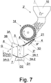
- a fourth embodiment of the device for sorting the spherical objects 1 that is presented in Fig. 7 comprises the feeder 2' of the spherical objects 1 and a sorting plate 3".
- the sorting plate 3" has the receiving region 4 for receiving the spherical objects from the feeder 2', as well as the sorting region 5, which comprises the good objects transferring region 6 and the defective objects transferring region 7.
- the sorting surface 3A in the sorting region 5 of the sorting plate 3" firstly descends and subsequently ascends between the receiving region 4 and the good objects transferring region 6.
- the sorting surface 3A comprises a first flat portion 3A-1, a second portion 3A-2 being a section of a cylinder and a third flat portion 3A-3.
- the sorting surface 3A between the receiving region 4 and the good objects transferring region 6 descends along the first flat portion 3A-1 and partly in the second portion 3A-2 and ascends partly in the second portion 3A-2 and in the third flat portion 3A-3. Downstream the receiving region 4 (in the direction of movement of the spherical objects 1 in the region where the sorting surface 3A descends), there is located the accelerating region 8 in which the spherical objects 1 are given kinetic energy, which is necessary for conducting the sorting process.
- the sorting plate 3" has a shape of a gutter element.
- the good spherical objects 1G reach the good objects transferring region 6, and the defective spherical objects 1D slide down to the defective objects transferring region 7.
- the feeder 2' of the spherical objects 1 and the feeding drum 14 are constructed similarly as in the previous embodiment.
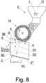
- a fifth embodiment of the device for sorting the spherical objects 1 shown in Fig. 8 comprises the feeder 2' of the spherical objects 1 and a flat sorting plate 3"'.
- the sorting plate 3'" has the receiving region 4 for receiving the spherical objects 1, the sorting region 5, which comprises the good objects transferring region 6 and the defective objects transferring region 7.
- the sorting surface 3A of the sorting plate 3"' ascends between the receiving region 4 and the good objects transferring region 6.
- the spherical objects 1 are accelerated by means of a rotary motion of the feeding drum 14, wherein any other feeding drum may be used for feeding the spherical objects 1.
Landscapes
- Sorting Of Articles (AREA)
- Feeding Of Articles To Conveyors (AREA)
Abstract
Description
- The present disclosure relates to sorting spherical objects.
- A device as described herein may be used for sorting different types of spherical objects, such as uniform or multi-part objects, solid or partially empty objects, objects comprising one material coated by another material or other types of such objects. The device is particularly useful when there is a need for fast sorting of spherical objects to select objects corresponding with certain requirements in terms of uniformness of an outer surface and/or distribution of the internal mass.
- The present disclosure presents the device in relation to an example related to sorting capsules used in tobacco industry, i.e. spheres having a stiff coating filled with aromatic substances. However, such device may be used for all other types of spherical objects.
- There are known various devices for sorting spherical objects. A
JP1999319728A - The object of the invention is a device for sorting spherical objects, the device comprising: a feeder for feeding the spherical objects; and a sorting plate comprising a receiving region for receiving the spherical objects and a sorting region, the sorting region comprising a good objects transferring region for transferring good spherical objects and a defective objects transferring region for transferring defective spherical objects; characterized in that the sorting plate comprises a sorting surface that ascends between the receiving region and the good objects transferring region.
- The sorting surface of the sorting plate may descend between the receiving region and the defective objects transferring region.
- The sorting plate may comprise an accelerating region between the receiving region and the good objects transferring region.
- The accelerating region may have a form of a feeding duct formed by the sorting surface of the sorting plate and by a rail located on the sorting surface.
- The accelerating region may be located upstream of the receiving region.
- The accelerating region may be located upstream of the sorting plate.
- The accelerating region may be formed by a tube.
- The sorting plate may have a form of a gutter element, wherein the good spherical objects move from the receiving region transversally through the gutter element to the good objects transferring region, and the defective spherical objects move downwards the sorting plate to the defective objects transferring region.
- The sorting surface may comprise a section of a cylinder, wherein the sorting surface is located such that generating lines of the section of the cylinder are directed towards the defective objects transferring region.
- The sorting surface may comprise a section of a cylinder, wherein the sorting surface is located such that generating lines of the section of the cylinder are directed transversally to a feeding duct, wherein the generating lines of the cylinder are inclined from a horizontal direction downwards below the feeding duct.
- The sorting plate may have an adjustable angular position, such that an edge of the sorting plate that adjoins the good objects transferring region may change its position in a vertical direction.
- The feeding duct may have an angular position that is adjustable with respect to a horizontal direction.
- The angular position of the feeding duct may be adjustable along with the angular position of the sorting plate.
- The sorting plate may have an angular position that is adjustable in a plane transversal to the feeding duct.
- The feeder may comprise a feeding drum that has on its circumferential surface sockets for transferring the spherical objects and a storage of the spherical objects located above the feeding drum.
- The feeding drum may have a circumferential groove that passes through the sockets, and wherein an ejector is located in the circumferential groove for ejecting the spherical objects from the sockets.
- A negative pressure may be supplied to the sockets.
- There is also disclosed a method for sorting spherical objects, the method comprising the steps of: feeding the spherical objects from a feeder onto a sorting plate, wherein the sorting plate comprises a receiving region for receiving the spherical objects and a sorting region, the sorting region comprising a good objects transferring region for transferring good spherical objects and a defective objects transferring region for transferring defective spherical objects; receiving the good spherical objects from the good objects transferring region and receiving defective spherical objects from the defective objects transferring region; characterized by: positioning the sorting plate such that a sorting surface of the sorting plate ascends between the receiving region and the good objects transferring region.
- The method may further comprise changing the configuration of the sorting plate during the sorting by means of at least one of the following methods:
- changing a vertical position of an edge of the sorting plate that is adjacent to the good objects transferring region;
- changing an angular position of a feeding duct for feeding the spherical objects with respect to a horizontal direction;
- changing an angular position of both a sorting plate and a feeding duct for feeding the spherical objects with respect to a horizontal direction;
- changing an angular position of the sorting plate in a plane which is transversal to a feeding duct for feeding the spherical objects.
- The device according to the invention has a simple construction and may be easily utilized for sorting objects of different sizes and weights.
- The present invention is shown by means of example embodiments in a drawing, in which:
-
Fig. 1 presents a device for sorting in a first embodiment in a side view; -
Fig. 2 presents the device for sorting in the first embodiment in a top view; -
Fig. 3 presents the device for sorting in a second embodiment in a side view; -
Fig. 4 presents the device for sorting in the second embodiment in a top view; -
Fig. 5 presents the device for sorting offigs. 3 and4 after angular adjustment of a sorting plate; -
Fig. 6 presents the device for sorting in a third embodiment in a top view; -
Fig. 7 presents the device for sorting in a fourth embodiment in a side view; and -
Fig. 8 presents the device for sorting in a fifth embodiment in a side view. - A device for sorting
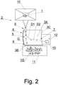
spherical objects 1 is presented in a first embodiment inFigs. 1 and2 . The device comprises afeeder 2 for feeding thespherical objects 1 and asorting plate 3. Thesorting plate 3 comprises areceiving region 4 for receiving thespherical objects 1 from thefeeder 2 and asorting region 5. Thesorting region 5 comprises a goodobjects transferring region 6 for transferring goodspherical objects 1G and a defectiveobjects transferring region 7 for transferring defectivespherical objects 1D. At least a portion of asorting surface 3A of thesorting plate 3 ascends between thereceiving region 4 and the goodobjects transferring region 6. Preferably, the goodobjects transferring region 6 is located substantially above thereceiving region 4, wherein a height level of thereceiving region 4 may be referenced in relation to the height level of a point for receiving thespherical objects 1 from thefeeder 2. An acceleratingregion 8 is located upstream (according to the direction of flow of the spherical objects 1) of thereceiving region 4. While moving along theaccelerating region 8, thespherical objects 1 gain kinetic energy that is useful in the sorting process. In this embodiment, the acceleratingregion 8 is afeeding duct 9 in a form of a tube that delivers thespherical objects 1 from astorage 10 of thefeeder 2. Thesorting plate 3 may have a form of a low trough element - in this embodiment thesorting plate 3 has a form of a cylindrical section, wherein generating lines of the cylinder are located transversally to thefeeding duct 9 downwards to the defectiveobjects transferring region 7. Thesorting surface 3A of thesorting plate 3 in thesorting region 5 descends between thereceiving region 4 and the defectiveobjects transferring region 7, i.e. the defectiveobjects transferring region 7 is located below thereceiving region 4. - The device for sorting the
spherical objects 1 comprises agood objects container 11 for receiving the goodspherical objects 1G, which is located below the goodobjects transferring region 6, as well as adefective objects container 12 for receiving the defective spherical objects ID, which is located below the defectiveobjects transferring region 7. The goodspherical objects 1G, which attained a certain velocity, roll along thesorting region 5 towards the goodobjects transferring region 6, pass anedge 3B that is adjacent to the goodobjects transferring region 6 and fall into thegood objects container 11. The defectivespherical objects 1D may have a non-spherical surface, for example may be elongated, indented, chipped, empty, or may be glued to each other or may have a non-uniform distribution of the internal mass. Such defective spherical objects ID, even though they attained some kinetic energy, may during their travel change their trajectory away from the trajectory expected for the goodspherical objects 1G. Consequently, the defectivespherical objects 1D do not reach the goodobjects transferring region 6, their velocity decreases, and consequently they slide or roll downwards to the defectiveobjects transferring region 7, pass anedge 3C and fall into thedefective objects container 12. Dashed lines present examples of trajectories of the spherical objects, wherein a line G presents the trajectory of the goodspherical object 1G, and lines D1 and D2 present trajectories of the defectivespherical objects 1D. The actual trajectories of the goodspherical objects 1G and the defectivespherical objects 1D depend on the shape of particular objects, a weight of the objects and a shape of the sorting surface, wherein each defect of the shape of the defectivespherical objects 1D may influence the trajectory of movement. The exemplary trajectories G, D1 and D2 are also shown for the other embodiments. -
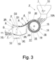
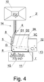
Figs. 3 ,4 and5 show a second embodiment of a device for sortingspherical objects 1. This device comprises a feeder 2' for feeding thespherical objects 1 and a sorting plate 3'. The sorting plate 3' comprises the receivingregion 4 for receiving thespherical objects 1 from the feeder 2' and the sortingregion 5, which comprises the goodobjects transferring region 6 and the defectiveobjects transferring region 7. The sortingsurface 3A in thesorting region 5 first descends and subsequently ascends between the receivingregion 4 and the goodobjects transferring region 6. In this embodiment, the acceleratingregion 8, wherein thespherical objects 1 gain kinetic energy, is defined by the descending portion of the sortingregion 5. A feeding duct 9' is located in the acceleratingregion 8. The feeding duct 9' is formed by the sortingsurface 3A and arail 13 having a curvature corresponding to the curvature of thesorting surface 3A and mounted on a surface 13A and on aprotrusion 3D. The sortingplate 3 has a shape of a gutter element. Thespherical objects 1 attain the kinetic energy, the goodspherical objects 1G roll transversally across the sortingplate 3 and reach the goodobjects transferring region 6, and the defectivespherical objects 1D slide down or roll to the defectiveobjects transferring region 7. The feeder 2' of thespherical objects 1 comprises thestorage 10, aduct 10A and a feedingdrum 14, from which thespherical objects 1 are transferred to the receivingregion 4. The feedingdrum 14 hassockets 15 located on itscircumferential surface 16. Thesockets 15 have a form of indentations, for example conical or spherical indentations, in which thespherical objects 1 are placed. Agroove 17 is made in thecircumferential surface 16 of the feedingdrum 14, wherein thegroove 17 passes through thesockets 15. A negative pressure may be supplied to thesockets 15thorough ducts 18 from a supply duct 19 (the components of the negative pressure supply system are not shown for simplicity of the drawing). Anejector 20, in a form of a flat arc, is inserted into thecircumferential groove 17, wherein during the rotation of the feedingdrum 14, the ejector is intended to push (eject) thespherical objects 1 out of thesockets 15.Fig. 5 shows the sorting plate 3' of the device ofFig. 3 and4 after performing an angular adjustment by rotating the sorting plate 3' with respect to an X axis of the feeding drum. During the adjustment, theedge 3B may be lowered or raised with respect to the position presented inFig. 3 (inFig. 5 , the edge is lowered). Such adjustment may be necessary after changing the weight of the spherical objects, which results in that thespherical objects 1 are given different kinetic energy. Part of the kinetic energy of the goodspherical objects 1G is converted into potential energy, and the velocity of the goodspherical objects 1G decreases. The adjustment of the height of theedge 3B allows to adapt the operation of the device to sortspherical objects 1 of different weights. - The adjustment of the position of the
sorting plate 3 or its components may be performed before starting the sorting, depending on the parameters of thespherical objects 1 being sorted. The adjustment may also be conducted during sorting, based on observation of thespherical objects objects transferring region 6 and from the defectiveobjects transferring region 7, such as to minimize the amount of thedefective objects 1D received from the goodobjects transferring region 6 and/or to minimize the amount of the goodspherical objects 1G received from the defectiveobjects transferring region 7. - A third embodiment of the device for sorting the
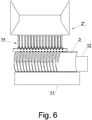
spherical objects 1 that is presented inFig. 6 comprises a plurality of single devices presented inFigs. 3 ,4 and5 . Afeeder 2" of thespherical objects 1 comprises a plurality of feedingdrums 14, wherein thespherical objects 1 are fed onto a plurality of sortingplates 3. - A fourth embodiment of the device for sorting the
spherical objects 1 that is presented inFig. 7 comprises the feeder 2' of thespherical objects 1 and asorting plate 3". The sortingplate 3" has the receivingregion 4 for receiving the spherical objects from the feeder 2', as well as the sortingregion 5, which comprises the goodobjects transferring region 6 and the defectiveobjects transferring region 7. The sortingsurface 3A in thesorting region 5 of thesorting plate 3" firstly descends and subsequently ascends between the receivingregion 4 and the goodobjects transferring region 6. The sortingsurface 3A comprises a firstflat portion 3A-1, asecond portion 3A-2 being a section of a cylinder and a thirdflat portion 3A-3. The sortingsurface 3A between the receivingregion 4 and the goodobjects transferring region 6 descends along the firstflat portion 3A-1 and partly in thesecond portion 3A-2 and ascends partly in thesecond portion 3A-2 and in the thirdflat portion 3A-3. Downstream the receiving region 4 (in the direction of movement of thespherical objects 1 in the region where thesorting surface 3A descends), there is located the acceleratingregion 8 in which thespherical objects 1 are given kinetic energy, which is necessary for conducting the sorting process. In the acceleratingregion 8 there is located the feeding duct 9' formed in thesorting plate 3" by theflat portion 3A-1 of thesorting surface 3A and theprotrusion 3D and thestraight rail 13 mounted on the portion of thesurface 3A-1 and on theprotrusion 3D. The sortingplate 3" has a shape of a gutter element. The goodspherical objects 1G reach the goodobjects transferring region 6, and the defectivespherical objects 1D slide down to the defectiveobjects transferring region 7. The feeder 2' of thespherical objects 1 and the feedingdrum 14 are constructed similarly as in the previous embodiment. - A fifth embodiment of the device for sorting the
spherical objects 1 shown inFig. 8 comprises the feeder 2' of thespherical objects 1 and aflat sorting plate 3"'. The sorting plate 3'" has the receivingregion 4 for receiving thespherical objects 1, the sortingregion 5, which comprises the goodobjects transferring region 6 and the defectiveobjects transferring region 7. The sortingsurface 3A of thesorting plate 3"' ascends between the receivingregion 4 and the goodobjects transferring region 6. Thespherical objects 1 are accelerated by means of a rotary motion of the feedingdrum 14, wherein any other feeding drum may be used for feeding thespherical objects 1. - Although the invention is presented in the drawings and the description and in relation to its preferred embodiments, these embodiments do not restrict nor limit the presented invention. It is therefore evident that changes, which come within the meaning and range of equivalency of the essence of the invention, may be made. The presented embodiments are therefore to be considered in all aspects as illustrative and not restrictive. According to the abovementioned, the scope of the invention is not restricted to the presented embodiments but is indicated by the appended claims.
Claims (15)
- A device for sorting spherical objects (1), the device comprising:- a feeder (2, 2', 2") for feeding the spherical objects (1); and- a sorting plate (3, 3', 3", 3"') comprising a receiving region (4) for receiving the spherical objects (1) and a sorting region (5), the sorting region (5) comprising a good objects transferring region (6) for transferring good spherical objects (1G) and a defective objects transferring region (7) for transferring defective spherical objects (1D);
characterized in that- the sorting plate (3, 3', 3", 3"') comprises a sorting surface (3A) that ascends between the receiving region (4) and the good objects transferring region (6). - The device according to claim 1, wherein the sorting surface (3A) of the sorting plate (3, 3', 3", 3"') descends between the receiving region (4) and the defective objects transferring region (7).
- The device according to claim 1 or 2, wherein the sorting plate (3, 3', 3", 3"') comprises an accelerating region (8) between the receiving region (4) and the good objects transferring region (6).
- The device according to claim 3, wherein the accelerating region (8) has a form of a feeding duct (9', 9") formed by the sorting surface (3A) of the sorting plate (3, 3', 3") and by a rail (13, 21) located on the sorting surface (3A).
- The device according to claim 1 or 2, wherein the accelerating region (8) is located upstream of the receiving region (4).
- The device according to claim 1 or 2, wherein the accelerating region (8) is located upstream of the sorting plate (3, 3', 3").
- The device according to claim 6, wherein the accelerating region (8) is formed by a tube.
- The device according to any of claims from 1 to 7, wherein the sorting plate (3, 3', 3") has a form of a trough element, wherein the good spherical objects (1G) move from the receiving region (4) transversally through the trough element to the good objects transferring region (6), and the defective spherical objects (1D) move downwards the sorting plate (3, 3', 3") to the defective objects transferring region (7).
- The device according to claim 8, wherein the sorting surface (3A) comprises a section of a cylinder, wherein the sorting surface (3A) is located such that generating lines of the section of the cylinder are directed towards the defective objects transferring region (7).
- The device according to claim 8, wherein the sorting surface (3A) comprises a section of a cylinder, wherein the sorting surface (3A) is located such that generating lines of the section of the cylinder are directed transversally to a feeding duct (9, 9', 9"), wherein the generating lines of the cylinder are inclined from a horizontal direction downwards below the feeding duct (9, 9', 9").
- The device according to any of claims from 1 to 10, wherein the sorting plate (3) has an adjustable angular position, such that an edge (3B) of the sorting plate (3) that adjoins the good objects transferring region (6) may change its position in a vertical direction.
- The device according to claim 4, wherein the feeding duct (9) has an angular position that is adjustable with respect to a horizontal direction.
- The device according to any of previous claims, wherein the feeder (2, 2', 2") comprises a feeding drum (14) that has on its circumferential surface (16) sockets (15) for transferring the spherical objects (1) and a storage (10) of the spherical objects (1) located above the feeding drum (14).
- A method for sorting spherical objects (1), the method comprising the steps of:- feeding the spherical objects (1) from a feeder (2, 2', 2") onto a sorting plate (3, 3', 3", 3"'), wherein the sorting plate (3, 3', 3", 3"') comprises a receiving region (4) for receiving the spherical objects (1) and a sorting region (5), the sorting region (5) comprising a good objects transferring region (6) for transferring good spherical objects (1G) and a defective objects transferring region (7) for transferring defective spherical objects (1D);- receiving the good spherical objects (1G) from the good objects transferring region (6) and receiving defective spherical objects (1D) from the defective objects transferring region (7);characterized by:- positioning the sorting plate (3, 3', 3", 3"') such that a sorting surface (3A) of the sorting plate (3, 3', 3", 3"') ascends between the receiving region (4) and the good objects transferring region (6).
- The method according to claim 14, further comprising changing the configuration of the sorting plate (3, 3', 3", 3"') during the sorting by means of at least one of the following methods:- changing a vertical position of an edge (3B) of the sorting plate (3) that is adjacent to the good objects transferring region (6);- changing an angular position of a feeding duct (9, 9', 9") for feeding the spherical objects (1) with respect to a horizontal direction;- changing an angular position of both a sorting plate (3) and a feeding duct (9, 9', 9") for feeding the spherical objects (1) with respect to a horizontal direction;- changing an angular position of the sorting plate (3) in a plane which is transversal to a feeding duct (9) for feeding the spherical objects (1).
Priority Applications (5)
| Application Number | Priority Date | Filing Date | Title |
|---|---|---|---|
| PL19173412T PL3736052T3 (en) | 2019-05-09 | 2019-05-09 | A device and a method for sorting spherical objects |
| EP19173412.8A EP3736052B1 (en) | 2019-05-09 | 2019-05-09 | A device and a method for sorting spherical objects |
| US16/853,459 US20200353509A1 (en) | 2019-05-09 | 2020-04-20 | Device and a method for sorting spherical objects |
| RU2020115324A RU2765907C2 (en) | 2019-05-09 | 2020-05-01 | Apparatus and method for sorting spherical objects |
| CN202010383948.5A CN111906030A (en) | 2019-05-09 | 2020-05-08 | Device and method for sorting spherical objects |
Applications Claiming Priority (1)
| Application Number | Priority Date | Filing Date | Title |
|---|---|---|---|
| EP19173412.8A EP3736052B1 (en) | 2019-05-09 | 2019-05-09 | A device and a method for sorting spherical objects |
Publications (2)
| Publication Number | Publication Date |
|---|---|
| EP3736052A1 true EP3736052A1 (en) | 2020-11-11 |
| EP3736052B1 EP3736052B1 (en) | 2022-02-16 |
Family
ID=66476437
Family Applications (1)
| Application Number | Title | Priority Date | Filing Date |
|---|---|---|---|
| EP19173412.8A Active EP3736052B1 (en) | 2019-05-09 | 2019-05-09 | A device and a method for sorting spherical objects |
Country Status (5)
| Country | Link |
|---|---|
| US (1) | US20200353509A1 (en) |
| EP (1) | EP3736052B1 (en) |
| CN (1) | CN111906030A (en) |
| PL (1) | PL3736052T3 (en) |
| RU (1) | RU2765907C2 (en) |
Families Citing this family (2)
| Publication number | Priority date | Publication date | Assignee | Title |
|---|---|---|---|---|
| CN113714110A (en) * | 2021-09-01 | 2021-11-30 | 福建永荣锦江股份有限公司 | Spinning masterbatch screening processingequipment |
| CN117900167B (en) * | 2024-03-20 | 2024-05-14 | 济南厚德耐磨材料有限公司 | Automatic sorting device for steel balls with surface defects |
Citations (3)
| Publication number | Priority date | Publication date | Assignee | Title |
|---|---|---|---|---|
| JPH11319728A (en) | 1998-05-15 | 1999-11-24 | Sumitomo Metal Mining Co Ltd | Single sphere sorting apparatus |
| US20100170832A1 (en) * | 2006-11-20 | 2010-07-08 | Hitachi Metals, Ltd. | Device and method of screening for individual balls |
| WO2014154626A1 (en) * | 2013-03-27 | 2014-10-02 | Heraeus Materials Technology Gmbh & Co. Kg | Solder sphere sorting |
Family Cites Families (9)
| Publication number | Priority date | Publication date | Assignee | Title |
|---|---|---|---|---|
| GB1144780A (en) * | 1966-09-27 | 1969-03-12 | Gunsons Sortex Ltd | Feeding device for elongated objects |
| NL7413994A (en) * | 1973-11-05 | 1975-05-07 | Hoechst Ag | METHOD AND DEVICE FOR THE SEPARATION OF NON-SPHERICAL PARTICLES FROM SPHERICAL PARTICLES |
| SU831226A1 (en) * | 1979-04-04 | 1981-05-23 | Предприятие П/Я А-1857 | Apparatus for sorting loose materials |
| SU1699666A1 (en) * | 1989-07-26 | 1991-12-23 | Курганский сельскохозяйственный институт | Metering distributor of seed cleaning machine |
| JP4697566B2 (en) * | 2000-08-08 | 2011-06-08 | 日立金属株式会社 | Oval sphere sorting method and apparatus |
| FR2844212B1 (en) * | 2002-09-06 | 2006-05-05 | Delarue Sas | METHOD AND INSTALLATION FOR THE AUTOMATIC MORPHOLOGICAL SORTING OF SUBSTANTIALLY SPHERICAL OBJECTS. |
| CN200981056Y (en) * | 2006-12-08 | 2007-11-28 | 华南农业大学 | Detection separator for table tennis |
| EP2859963A1 (en) * | 2013-10-11 | 2015-04-15 | Sikora Ag | Method and device for sorting bulk material |
| RU187553U1 (en) * | 2018-03-27 | 2019-03-12 | Валентин Яковлевич Потапов | SEPARATOR FOR SEPARATION OF BULK MATERIALS BY FRICTIONAL MAGNETIC CHARACTERISTICS |
-
2019
- 2019-05-09 EP EP19173412.8A patent/EP3736052B1/en active Active
- 2019-05-09 PL PL19173412T patent/PL3736052T3/en unknown
-
2020
- 2020-04-20 US US16/853,459 patent/US20200353509A1/en not_active Abandoned
- 2020-05-01 RU RU2020115324A patent/RU2765907C2/en active
- 2020-05-08 CN CN202010383948.5A patent/CN111906030A/en active Pending
Patent Citations (3)
| Publication number | Priority date | Publication date | Assignee | Title |
|---|---|---|---|---|
| JPH11319728A (en) | 1998-05-15 | 1999-11-24 | Sumitomo Metal Mining Co Ltd | Single sphere sorting apparatus |
| US20100170832A1 (en) * | 2006-11-20 | 2010-07-08 | Hitachi Metals, Ltd. | Device and method of screening for individual balls |
| WO2014154626A1 (en) * | 2013-03-27 | 2014-10-02 | Heraeus Materials Technology Gmbh & Co. Kg | Solder sphere sorting |
Also Published As
| Publication number | Publication date |
|---|---|
| PL3736052T3 (en) | 2022-05-23 |
| RU2765907C2 (en) | 2022-02-04 |
| RU2020115324A (en) | 2021-11-01 |
| RU2020115324A3 (en) | 2021-12-01 |
| EP3736052B1 (en) | 2022-02-16 |
| US20200353509A1 (en) | 2020-11-12 |
| CN111906030A (en) | 2020-11-10 |
Similar Documents
| Publication | Publication Date | Title |
|---|---|---|
| US20200353509A1 (en) | Device and a method for sorting spherical objects | |
| EP2349875B1 (en) | Inspecting and sorting apparatus, and method for retrofitting | |
| US6367228B1 (en) | Capsule part carrier in a filling and sealing machine for two-part capsules | |
| US7789215B1 (en) | Centrifugal/vibratory feeder system | |
| US20090151305A1 (en) | Method and apparatus for orienting articles | |
| US20010010788A1 (en) | Method and apparatus for application of 360 degree coatings to articles | |
| CN101456485A (en) | Pre-form sorting apparatus | |
| EP3135089A1 (en) | Sowing machine and method for operating a sowing machine | |
| US7040489B2 (en) | Object orienting and sorting apparatus | |
| JPH04361914A (en) | Method and device for feeding columnar articles from irregular set thereof at high speed to assemble them | |
| EP2295350A1 (en) | Apparatus for unscrambling and aligning preforms | |
| EP3137278A1 (en) | Device and method for transporting preforms in the region of a blow-molding machine | |
| DE102008027624A1 (en) | Method for controlling and sorting small articles, involves supplying number of small articles by conveying unit per time unit up to separation unit, and small articles are lined up and transported one behind other in conveying tracks | |
| FI61452B (en) | OVER ANCHORAGE FOER AOTSKILJANDE AV MONTAGEDELAR FRAON VARANDRA | |
| US20240131595A1 (en) | Powder supply assembly for additive manufacturing | |
| US2764351A (en) | Machines for delivering predetermined quantities of articles | |
| US9592967B2 (en) | Preform conveying apparatus and method | |
| US8122921B2 (en) | Device for distribution of at least one granular product in a container filling device and method for filling using such a device | |
| US8894904B2 (en) | Star distributor | |
| JP2001122432A (en) | Supply device for small parts and carrier channel | |
| US6978899B2 (en) | Apparatus for sorting wood chips in separate fractions | |
| DK151250B (en) | SPREADING ORGANIZATION IN A STORAGE CONTAINER FOR EQUAL FILLING OF THE CONTAINER WITH A GRANULATED MATERIAL | |
| PL241335B1 (en) | Device for sorting spherical objects and a method of sorting spherical objects | |
| DE102015114155A1 (en) | Dosing device for granular material with pre-metering unit | |
| CA2595076A1 (en) | Pressing system |
Legal Events
| Date | Code | Title | Description |
|---|---|---|---|
| PUAI | Public reference made under article 153(3) epc to a published international application that has entered the european phase |
Free format text: ORIGINAL CODE: 0009012 |
|
| STAA | Information on the status of an ep patent application or granted ep patent |
Free format text: STATUS: THE APPLICATION HAS BEEN PUBLISHED |
|
| AK | Designated contracting states |
Kind code of ref document: A1 Designated state(s): AL AT BE BG CH CY CZ DE DK EE ES FI FR GB GR HR HU IE IS IT LI LT LU LV MC MK MT NL NO PL PT RO RS SE SI SK SM TR |
|
| AX | Request for extension of the european patent |
Extension state: BA ME |
|
| STAA | Information on the status of an ep patent application or granted ep patent |
Free format text: STATUS: REQUEST FOR EXAMINATION WAS MADE |
|
| 17P | Request for examination filed |
Effective date: 20210508 |
|
| RBV | Designated contracting states (corrected) |
Designated state(s): AL AT BE BG CH CY CZ DE DK EE ES FI FR GB GR HR HU IE IS IT LI LT LU LV MC MK MT NL NO PL PT RO RS SE SI SK SM TR |
|
| GRAP | Despatch of communication of intention to grant a patent |
Free format text: ORIGINAL CODE: EPIDOSNIGR1 |
|
| STAA | Information on the status of an ep patent application or granted ep patent |
Free format text: STATUS: GRANT OF PATENT IS INTENDED |
|
| GRAJ | Information related to disapproval of communication of intention to grant by the applicant or resumption of examination proceedings by the epo deleted |
Free format text: ORIGINAL CODE: EPIDOSDIGR1 |
|
| GRAP | Despatch of communication of intention to grant a patent |
Free format text: ORIGINAL CODE: EPIDOSNIGR1 |
|
| INTG | Intention to grant announced |
Effective date: 20211012 |
|
| INTG | Intention to grant announced |
Effective date: 20211027 |
|
| GRAS | Grant fee paid |
Free format text: ORIGINAL CODE: EPIDOSNIGR3 |
|
| GRAA | (expected) grant |
Free format text: ORIGINAL CODE: 0009210 |
|
| STAA | Information on the status of an ep patent application or granted ep patent |
Free format text: STATUS: THE PATENT HAS BEEN GRANTED |
|
| AK | Designated contracting states |
Kind code of ref document: B1 Designated state(s): AL AT BE BG CH CY CZ DE DK EE ES FI FR GB GR HR HU IE IS IT LI LT LU LV MC MK MT NL NO PL PT RO RS SE SI SK SM TR |
|
| REG | Reference to a national code |
Ref country code: GB Ref legal event code: FG4D |
|
| REG | Reference to a national code |
Ref country code: CH Ref legal event code: EP |
|
| REG | Reference to a national code |
Ref country code: DE Ref legal event code: R096 Ref document number: 602019011591 Country of ref document: DE |
|
| REG | Reference to a national code |
Ref country code: AT Ref legal event code: REF Ref document number: 1468564 Country of ref document: AT Kind code of ref document: T Effective date: 20220315 |
|
| REG | Reference to a national code |
Ref country code: IE Ref legal event code: FG4D |
|
| REG | Reference to a national code |
Ref country code: LT Ref legal event code: MG9D |
|
| REG | Reference to a national code |
Ref country code: AT Ref legal event code: MK05 Ref document number: 1468564 Country of ref document: AT Kind code of ref document: T Effective date: 20220216 |
|
| PG25 | Lapsed in a contracting state [announced via postgrant information from national office to epo] |
Ref country code: SE Free format text: LAPSE BECAUSE OF FAILURE TO SUBMIT A TRANSLATION OF THE DESCRIPTION OR TO PAY THE FEE WITHIN THE PRESCRIBED TIME-LIMIT Effective date: 20220216 Ref country code: RS Free format text: LAPSE BECAUSE OF FAILURE TO SUBMIT A TRANSLATION OF THE DESCRIPTION OR TO PAY THE FEE WITHIN THE PRESCRIBED TIME-LIMIT Effective date: 20220216 Ref country code: PT Free format text: LAPSE BECAUSE OF FAILURE TO SUBMIT A TRANSLATION OF THE DESCRIPTION OR TO PAY THE FEE WITHIN THE PRESCRIBED TIME-LIMIT Effective date: 20220616 Ref country code: NO Free format text: LAPSE BECAUSE OF FAILURE TO SUBMIT A TRANSLATION OF THE DESCRIPTION OR TO PAY THE FEE WITHIN THE PRESCRIBED TIME-LIMIT Effective date: 20220516 Ref country code: NL Free format text: LAPSE BECAUSE OF FAILURE TO SUBMIT A TRANSLATION OF THE DESCRIPTION OR TO PAY THE FEE WITHIN THE PRESCRIBED TIME-LIMIT Effective date: 20220216 Ref country code: LT Free format text: LAPSE BECAUSE OF FAILURE TO SUBMIT A TRANSLATION OF THE DESCRIPTION OR TO PAY THE FEE WITHIN THE PRESCRIBED TIME-LIMIT Effective date: 20220216 Ref country code: HR Free format text: LAPSE BECAUSE OF FAILURE TO SUBMIT A TRANSLATION OF THE DESCRIPTION OR TO PAY THE FEE WITHIN THE PRESCRIBED TIME-LIMIT Effective date: 20220216 Ref country code: ES Free format text: LAPSE BECAUSE OF FAILURE TO SUBMIT A TRANSLATION OF THE DESCRIPTION OR TO PAY THE FEE WITHIN THE PRESCRIBED TIME-LIMIT Effective date: 20220216 |
|
| PG25 | Lapsed in a contracting state [announced via postgrant information from national office to epo] |
Ref country code: LV Free format text: LAPSE BECAUSE OF FAILURE TO SUBMIT A TRANSLATION OF THE DESCRIPTION OR TO PAY THE FEE WITHIN THE PRESCRIBED TIME-LIMIT Effective date: 20220216 Ref country code: GR Free format text: LAPSE BECAUSE OF FAILURE TO SUBMIT A TRANSLATION OF THE DESCRIPTION OR TO PAY THE FEE WITHIN THE PRESCRIBED TIME-LIMIT Effective date: 20220517 Ref country code: FI Free format text: LAPSE BECAUSE OF FAILURE TO SUBMIT A TRANSLATION OF THE DESCRIPTION OR TO PAY THE FEE WITHIN THE PRESCRIBED TIME-LIMIT Effective date: 20220216 Ref country code: AT Free format text: LAPSE BECAUSE OF FAILURE TO SUBMIT A TRANSLATION OF THE DESCRIPTION OR TO PAY THE FEE WITHIN THE PRESCRIBED TIME-LIMIT Effective date: 20220216 |
|
| PG25 | Lapsed in a contracting state [announced via postgrant information from national office to epo] |
Ref country code: IS Free format text: LAPSE BECAUSE OF FAILURE TO SUBMIT A TRANSLATION OF THE DESCRIPTION OR TO PAY THE FEE WITHIN THE PRESCRIBED TIME-LIMIT Effective date: 20220617 |
|
| PG25 | Lapsed in a contracting state [announced via postgrant information from national office to epo] |
Ref country code: SM Free format text: LAPSE BECAUSE OF FAILURE TO SUBMIT A TRANSLATION OF THE DESCRIPTION OR TO PAY THE FEE WITHIN THE PRESCRIBED TIME-LIMIT Effective date: 20220216 Ref country code: SK Free format text: LAPSE BECAUSE OF FAILURE TO SUBMIT A TRANSLATION OF THE DESCRIPTION OR TO PAY THE FEE WITHIN THE PRESCRIBED TIME-LIMIT Effective date: 20220216 Ref country code: RO Free format text: LAPSE BECAUSE OF FAILURE TO SUBMIT A TRANSLATION OF THE DESCRIPTION OR TO PAY THE FEE WITHIN THE PRESCRIBED TIME-LIMIT Effective date: 20220216 Ref country code: EE Free format text: LAPSE BECAUSE OF FAILURE TO SUBMIT A TRANSLATION OF THE DESCRIPTION OR TO PAY THE FEE WITHIN THE PRESCRIBED TIME-LIMIT Effective date: 20220216 Ref country code: DK Free format text: LAPSE BECAUSE OF FAILURE TO SUBMIT A TRANSLATION OF THE DESCRIPTION OR TO PAY THE FEE WITHIN THE PRESCRIBED TIME-LIMIT Effective date: 20220216 Ref country code: CZ Free format text: LAPSE BECAUSE OF FAILURE TO SUBMIT A TRANSLATION OF THE DESCRIPTION OR TO PAY THE FEE WITHIN THE PRESCRIBED TIME-LIMIT Effective date: 20220216 |
|
| REG | Reference to a national code |
Ref country code: DE Ref legal event code: R097 Ref document number: 602019011591 Country of ref document: DE |
|
| PG25 | Lapsed in a contracting state [announced via postgrant information from national office to epo] |
Ref country code: AL Free format text: LAPSE BECAUSE OF FAILURE TO SUBMIT A TRANSLATION OF THE DESCRIPTION OR TO PAY THE FEE WITHIN THE PRESCRIBED TIME-LIMIT Effective date: 20220216 |
|
| PLBE | No opposition filed within time limit |
Free format text: ORIGINAL CODE: 0009261 |
|
| STAA | Information on the status of an ep patent application or granted ep patent |
Free format text: STATUS: NO OPPOSITION FILED WITHIN TIME LIMIT |
|
| REG | Reference to a national code |
Ref country code: BE Ref legal event code: MM Effective date: 20220531 |
|
| 26N | No opposition filed |
Effective date: 20221117 |
|
| PG25 | Lapsed in a contracting state [announced via postgrant information from national office to epo] |
Ref country code: MC Free format text: LAPSE BECAUSE OF FAILURE TO SUBMIT A TRANSLATION OF THE DESCRIPTION OR TO PAY THE FEE WITHIN THE PRESCRIBED TIME-LIMIT Effective date: 20220216 Ref country code: LU Free format text: LAPSE BECAUSE OF NON-PAYMENT OF DUE FEES Effective date: 20220509 |
|
| PG25 | Lapsed in a contracting state [announced via postgrant information from national office to epo] |
Ref country code: SI Free format text: LAPSE BECAUSE OF FAILURE TO SUBMIT A TRANSLATION OF THE DESCRIPTION OR TO PAY THE FEE WITHIN THE PRESCRIBED TIME-LIMIT Effective date: 20220216 |
|
| PG25 | Lapsed in a contracting state [announced via postgrant information from national office to epo] |
Ref country code: IE Free format text: LAPSE BECAUSE OF NON-PAYMENT OF DUE FEES Effective date: 20220509 Ref country code: FR Free format text: LAPSE BECAUSE OF NON-PAYMENT OF DUE FEES Effective date: 20220531 |
|
| PG25 | Lapsed in a contracting state [announced via postgrant information from national office to epo] |
Ref country code: BE Free format text: LAPSE BECAUSE OF NON-PAYMENT OF DUE FEES Effective date: 20220531 |
|
| PGFP | Annual fee paid to national office [announced via postgrant information from national office to epo] |
Ref country code: PL Payment date: 20230309 Year of fee payment: 5 |
|
| P01 | Opt-out of the competence of the unified patent court (upc) registered |
Effective date: 20230528 |
|
| PGFP | Annual fee paid to national office [announced via postgrant information from national office to epo] |
Ref country code: IT Payment date: 20230519 Year of fee payment: 5 Ref country code: DE Payment date: 20230530 Year of fee payment: 5 Ref country code: CH Payment date: 20230610 Year of fee payment: 5 Ref country code: BG Payment date: 20230511 Year of fee payment: 5 |
|
| PGFP | Annual fee paid to national office [announced via postgrant information from national office to epo] |
Ref country code: GB Payment date: 20230529 Year of fee payment: 5 |
|
| PG25 | Lapsed in a contracting state [announced via postgrant information from national office to epo] |
Ref country code: MK Free format text: LAPSE BECAUSE OF FAILURE TO SUBMIT A TRANSLATION OF THE DESCRIPTION OR TO PAY THE FEE WITHIN THE PRESCRIBED TIME-LIMIT Effective date: 20220216 Ref country code: CY Free format text: LAPSE BECAUSE OF FAILURE TO SUBMIT A TRANSLATION OF THE DESCRIPTION OR TO PAY THE FEE WITHIN THE PRESCRIBED TIME-LIMIT Effective date: 20220216 |