EP3735898B1 - Dispositif de dilatation à ballonnet - Google Patents
Dispositif de dilatation à ballonnet Download PDFInfo
- Publication number
- EP3735898B1 EP3735898B1 EP19192372.1A EP19192372A EP3735898B1 EP 3735898 B1 EP3735898 B1 EP 3735898B1 EP 19192372 A EP19192372 A EP 19192372A EP 3735898 B1 EP3735898 B1 EP 3735898B1
- Authority
- EP
- European Patent Office
- Prior art keywords
- dilation device
- balloon
- balloon dilation
- shaft
- sensor coil
- Prior art date
- Legal status (The legal status is an assumption and is not a legal conclusion. Google has not performed a legal analysis and makes no representation as to the accuracy of the status listed.)
- Active
Links
- 230000010339 dilation Effects 0.000 title claims description 347
- 239000012530 fluid Substances 0.000 claims description 82
- 239000003550 marker Substances 0.000 claims description 49
- 238000001514 detection method Methods 0.000 claims description 48
- 238000000034 method Methods 0.000 claims description 25
- 230000005672 electromagnetic field Effects 0.000 claims description 22
- 238000012800 visualization Methods 0.000 claims description 15
- 239000000463 material Substances 0.000 claims description 7
- 238000007493 shaping process Methods 0.000 description 18
- 238000005452 bending Methods 0.000 description 16
- 210000002388 eustachian tube Anatomy 0.000 description 16
- 238000001356 surgical procedure Methods 0.000 description 12
- 238000009429 electrical wiring Methods 0.000 description 9
- 230000000916 dilatatory effect Effects 0.000 description 7
- 230000008901 benefit Effects 0.000 description 4
- 210000000959 ear middle Anatomy 0.000 description 4
- 210000003097 mucus Anatomy 0.000 description 4
- 210000003695 paranasal sinus Anatomy 0.000 description 4
- 229920001343 polytetrafluoroethylene Polymers 0.000 description 4
- 239000004810 polytetrafluoroethylene Substances 0.000 description 4
- 229910000831 Steel Inorganic materials 0.000 description 3
- 230000009286 beneficial effect Effects 0.000 description 3
- 230000008859 change Effects 0.000 description 3
- 238000010438 heat treatment Methods 0.000 description 3
- 239000007788 liquid Substances 0.000 description 3
- 239000010959 steel Substances 0.000 description 3
- 238000002591 computed tomography Methods 0.000 description 2
- 238000010586 diagram Methods 0.000 description 2
- 230000005489 elastic deformation Effects 0.000 description 2
- 239000000835 fiber Substances 0.000 description 2
- 238000003780 insertion Methods 0.000 description 2
- 230000037431 insertion Effects 0.000 description 2
- 230000002262 irrigation Effects 0.000 description 2
- 238000003973 irrigation Methods 0.000 description 2
- 239000000203 mixture Substances 0.000 description 2
- 210000003928 nasal cavity Anatomy 0.000 description 2
- HLXZNVUGXRDIFK-UHFFFAOYSA-N nickel titanium Chemical compound [Ti].[Ti].[Ti].[Ti].[Ti].[Ti].[Ti].[Ti].[Ti].[Ti].[Ti].[Ni].[Ni].[Ni].[Ni].[Ni].[Ni].[Ni].[Ni].[Ni].[Ni].[Ni].[Ni].[Ni].[Ni] HLXZNVUGXRDIFK-UHFFFAOYSA-N 0.000 description 2
- 229910001000 nickel titanium Inorganic materials 0.000 description 2
- -1 polytetrafluoroethylene Polymers 0.000 description 2
- 229920002635 polyurethane Polymers 0.000 description 2
- 239000004814 polyurethane Substances 0.000 description 2
- 230000008569 process Effects 0.000 description 2
- 201000009890 sinusitis Diseases 0.000 description 2
- 210000003625 skull Anatomy 0.000 description 2
- 238000003325 tomography Methods 0.000 description 2
- 238000013519 translation Methods 0.000 description 2
- 230000014616 translation Effects 0.000 description 2
- 208000036829 Device dislocation Diseases 0.000 description 1
- 206010020751 Hypersensitivity Diseases 0.000 description 1
- 239000004677 Nylon Substances 0.000 description 1
- 206010033078 Otitis media Diseases 0.000 description 1
- 230000007815 allergy Effects 0.000 description 1
- 238000000137 annealing Methods 0.000 description 1
- 238000004891 communication Methods 0.000 description 1
- 201000010099 disease Diseases 0.000 description 1
- 208000037265 diseases, disorders, signs and symptoms Diseases 0.000 description 1
- 238000006073 displacement reaction Methods 0.000 description 1
- 229940079593 drug Drugs 0.000 description 1
- 239000003814 drug Substances 0.000 description 1
- 230000000694 effects Effects 0.000 description 1
- 210000001214 frontal sinus Anatomy 0.000 description 1
- 230000006698 induction Effects 0.000 description 1
- 208000015181 infectious disease Diseases 0.000 description 1
- 210000004086 maxillary sinus Anatomy 0.000 description 1
- 239000012528 membrane Substances 0.000 description 1
- 239000002184 metal Substances 0.000 description 1
- 210000001989 nasopharynx Anatomy 0.000 description 1
- 229920001778 nylon Polymers 0.000 description 1
- 239000004033 plastic Substances 0.000 description 1
- 229920003023 plastic Polymers 0.000 description 1
- 229920000728 polyester Polymers 0.000 description 1
- 229920001296 polysiloxane Polymers 0.000 description 1
- 238000012545 processing Methods 0.000 description 1
- 210000003718 sphenoid sinus Anatomy 0.000 description 1
- 230000009747 swallowing Effects 0.000 description 1
- 230000008961 swelling Effects 0.000 description 1
- 210000001519 tissue Anatomy 0.000 description 1
- 230000009466 transformation Effects 0.000 description 1
Images


Classifications
-
- A—HUMAN NECESSITIES
- A61—MEDICAL OR VETERINARY SCIENCE; HYGIENE
- A61B—DIAGNOSIS; SURGERY; IDENTIFICATION
- A61B5/00—Measuring for diagnostic purposes; Identification of persons
- A61B5/06—Devices, other than using radiation, for detecting or locating foreign bodies ; determining position of probes within or on the body of the patient
- A61B5/061—Determining position of a probe within the body employing means separate from the probe, e.g. sensing internal probe position employing impedance electrodes on the surface of the body
- A61B5/062—Determining position of a probe within the body employing means separate from the probe, e.g. sensing internal probe position employing impedance electrodes on the surface of the body using magnetic field
-
- A—HUMAN NECESSITIES
- A61—MEDICAL OR VETERINARY SCIENCE; HYGIENE
- A61B—DIAGNOSIS; SURGERY; IDENTIFICATION
- A61B17/00—Surgical instruments, devices or methods, e.g. tourniquets
- A61B17/24—Surgical instruments, devices or methods, e.g. tourniquets for use in the oral cavity, larynx, bronchial passages or nose; Tongue scrapers
-
- A—HUMAN NECESSITIES
- A61—MEDICAL OR VETERINARY SCIENCE; HYGIENE
- A61B—DIAGNOSIS; SURGERY; IDENTIFICATION
- A61B34/00—Computer-aided surgery; Manipulators or robots specially adapted for use in surgery
- A61B34/20—Surgical navigation systems; Devices for tracking or guiding surgical instruments, e.g. for frameless stereotaxis
-
- A—HUMAN NECESSITIES
- A61—MEDICAL OR VETERINARY SCIENCE; HYGIENE
- A61B—DIAGNOSIS; SURGERY; IDENTIFICATION
- A61B5/00—Measuring for diagnostic purposes; Identification of persons
- A61B5/68—Arrangements of detecting, measuring or recording means, e.g. sensors, in relation to patient
- A61B5/6846—Arrangements of detecting, measuring or recording means, e.g. sensors, in relation to patient specially adapted to be brought in contact with an internal body part, i.e. invasive
- A61B5/6847—Arrangements of detecting, measuring or recording means, e.g. sensors, in relation to patient specially adapted to be brought in contact with an internal body part, i.e. invasive mounted on an invasive device
- A61B5/6852—Catheters
- A61B5/6853—Catheters with a balloon
-
- A—HUMAN NECESSITIES
- A61—MEDICAL OR VETERINARY SCIENCE; HYGIENE
- A61M—DEVICES FOR INTRODUCING MEDIA INTO, OR ONTO, THE BODY; DEVICES FOR TRANSDUCING BODY MEDIA OR FOR TAKING MEDIA FROM THE BODY; DEVICES FOR PRODUCING OR ENDING SLEEP OR STUPOR
- A61M29/00—Dilators with or without means for introducing media, e.g. remedies
- A61M29/02—Dilators made of swellable material
-
- A—HUMAN NECESSITIES
- A61—MEDICAL OR VETERINARY SCIENCE; HYGIENE
- A61B—DIAGNOSIS; SURGERY; IDENTIFICATION
- A61B34/00—Computer-aided surgery; Manipulators or robots specially adapted for use in surgery
- A61B34/10—Computer-aided planning, simulation or modelling of surgical operations
- A61B2034/101—Computer-aided simulation of surgical operations
- A61B2034/105—Modelling of the patient, e.g. for ligaments or bones
-
- A—HUMAN NECESSITIES
- A61—MEDICAL OR VETERINARY SCIENCE; HYGIENE
- A61B—DIAGNOSIS; SURGERY; IDENTIFICATION
- A61B34/00—Computer-aided surgery; Manipulators or robots specially adapted for use in surgery
- A61B34/20—Surgical navigation systems; Devices for tracking or guiding surgical instruments, e.g. for frameless stereotaxis
- A61B2034/2046—Tracking techniques
- A61B2034/2051—Electromagnetic tracking systems
-
- A—HUMAN NECESSITIES
- A61—MEDICAL OR VETERINARY SCIENCE; HYGIENE
- A61B—DIAGNOSIS; SURGERY; IDENTIFICATION
- A61B90/00—Instruments, implements or accessories specially adapted for surgery or diagnosis and not covered by any of the groups A61B1/00 - A61B50/00, e.g. for luxation treatment or for protecting wound edges
- A61B90/39—Markers, e.g. radio-opaque or breast lesions markers
- A61B2090/3966—Radiopaque markers visible in an X-ray image
Definitions
- the invention relates to a balloon dilation device, a medical system comprising a balloon dilation device and a method for determining position and orientation of a balloon dilation device.
- Balloon dilation refers to the dilation of a cavity or passageway of a human body with a balloon.
- the human skull comprises a group of four paired air-filled spaces known as paranasal sinuses that surround the nasal cavity.
- Each of the paranasal sinuses opens into the nasal cavity via small orifices.
- Sinusitis can be treated, e.g., by means of balloon sinuplasty.
- Sinuplasty often includes using a balloon over-a-wire catheter to dilate sinus passageways to restore the normal drainage.
- a flexible guide wire is inserted through the nostril and guided to a sinus cavity.
- guide wires are used that have a light source at their tip for emitting light that can be seen by a surgeon through the patient's skin. The surgeon can thus follow the guide wire tip through the skin of a patient.
- a balloon catheter is advanced over the guide wire and positioned in the blocked sinus cavity. When the balloon catheter is positioned in the sinus cavity, its balloon is inflated to dilate the sinus openings and to restore normal drainage.
- Balloon catheters that include a movable shaft and methods for treating a sinus cavity of a subject with such a balloon catheter are described inter alia in US 10,022,525 B2 and US 2017/0028112 A1 .
- a passageway in the human skull that can be dilated with a balloon is the Eustachian tube which links the nasopharynx to the middle ear.
- the Eustachian tube is closed, however, it can open, e.g., during swallowing. In its open state the Eustachian tube can provide pressure equalization between the middle ear and the atmosphere.
- Another function of the Eustachian tube is to drain mucus from the middle ear.
- the function of the Eustachian tube can be disrupted, e.g., by swelling or by blockage, e.g., as a result of a cold or allergies.
- the Eustachian tube can be dilated with a balloon of a balloon dilation catheter to restore normal drainage and to achieve pressure equalization.
- a method for dilating a Eustachian tube of a patient with a dilation device is described, e.g., in US 2010/0274188 A1 .
- a device including a guide catheter and a balloon dilation catheter for dilating a Eustachian tube of a patient is disclosed in US 2018/0296811 A1 .
- US 2006/0004286 A1 discloses a sensor equipped dilation catheter comprising a shaft comprising a single, multi-lumen tube, a proximal Luer hub, a balloon, sensor(s) and sensor leads.
- US 2018/0036009 A1 discloses a catheter including a position sensor, a device and a handle.
- the device can comprise an inflatable balloon.
- the position sensor is attached to a distal end of the catheter.
- the device is movable along the catheter.
- the object is achieved by a balloon dilation device having a distal end and a proximal end.
- the balloon dilation device comprises a handle, a shaft, an inflatable balloon and at least one sensor coil.
- the handle extends from the proximal end of the balloon dilation device towards the distal end of the balloon dilation device.
- the shaft extends from the distal end of the balloon dilation device towards the proximal end of the balloon dilation device, said shaft having an inflation lumen.
- the inflatable balloon is fixedly arranged at the shaft.
- the balloon is fluidly connected to the inflation lumen such that the balloon can be inflated and deflated by feeding a fluid through the inflation lumen into or out of the balloon.
- the at least one sensor coil is arranged at the shaft.
- the at least one sensor coil is configured for capturing an electromagnetic field and for providing a sensor coil signal representing position and orientation of the sensor coil.
- the balloon dilation device comprises a second sensor coil that is arranged at the shaft, wherein the second sensor coil is displaced at a distance in longitudinal direction from the at least one sensor coil.
- the shaft has a malleable tip region extending from the distal end of the balloon dilation device toward the proximal end of the balloon dilation device.
- the at least one sensor coil is arranged at or at least close to the distal end of the shaft in the malleable region.
- the second sensor coil is arranged at the shaft adjacent to the malleable tip region.
- the balloon dilation device according to the invention is suitable for dilating a sinus cavity and the Eustachian tube of a patient.
- the balloon dilation device does not need to be modified in order to dilate either a sinus cavity or a Eustachian tube.
- the balloon dilation device can be inserted through the nostril of a patient and guided to either the sinus cavity or a Eustachian tube.
- the invention includes the recognition that a balloon dilation device such as a balloon catheter has to be guided through the human body in minimal invasive surgery and positioned in a sinus cavity before inflating the balloon.
- a guide wire has to be inserted into the human body over which, in a second step, the balloon dilation device is advanced.
- a typical guide wire used in sinuplasty has a light source at its tip.
- the surgeon typically, has to rely on a light spot as seen from outside through the skin. Thus, the surgeon cannot follow the guide wire or balloon dilation device inside the human body while guiding the guide wire or balloon dilation device.
- position and orientation of the balloon dilation device in relation to a human body can be determined by means of an electromagnetic position detection system.
- position and orientation of the at least one sensor coil are determined with the position detection system.
- position and orientation of the balloon dilation device can be calculated.
- positions of the at least one sensor coil can be determined while moving the at least one sensor coil relative to, e.g., a field generator generating an electromagnetic field. From repeatedly determined positions of the at least one sensor coil, positions of the balloon dilation device moved relative to a position detection system can be determined and, thus, the position of the balloon dilation device can be tracked while guiding the balloon dilation device.
- an electromagnetic position detection system for determining position and orientation of the at least one sensor coil, can be used that comprises a field generator for generating an alternating electromagnetic field.
- a current is induced in the at least one sensor coil.
- the current induced in the at least one sensor coil depends on the position and orientation of the sensor coil in the alternating electromagnetic field.
- position and orientation of the at least one sensor coil can be determined.
- position and orientation of the balloon dilation device can be calculated by a position detection system based on the detected position and orientation of the at least one sensor coil.
- position and orientation of the balloon dilation device equipped with at least one sensor coil can be detected by means of such a position detection system and the position of the balloon dilation device can be displayed in sectional images of a patient's body part obtained, e.g., by tomography.
- the surgeon using the balloon dilation device according to the invention can follow the position of the balloon dilation device inside a human body on a monitor displaying sectional images and a digital representation of the balloon dilation device while guiding the balloon dilation device through the human body.
- a surgeon can adapt the way of the moving the balloon dilation device, e.g., an applied pressure or an angle of the balloon dilation device to a body part, according to the determined actual position and orientation of the balloon dilation device inside the human body.
- position and orientation of the balloon dilation device equipped with at least one sensor coil can be directly tracked with a position detection system, initially using a guide wire for finding a cavity becomes obsolete.
- the balloon dilation device according to invention the number of steps necessary to position a balloon dilation device in a balloon cavity can be reduced and likewise surgery time can be saved.
- a fluid can be a gas or a liquid.
- a gas e.g., air
- a liquid can be fed into the balloon through the inflation lumen.
- balloon and inflation lumen are in fluid communication.
- the fluid inside the balloon can be removed, i.e., fed out of the balloon, to deflate the balloon.
- the handle comprises an attachment for attaching a fluid source to the inflation lumen, e.g., via a tube, for feeding a fluid through the inflation lumen into the balloon.
- the inflation lumen can extend from said attachment for attaching a fluid source through the handle and the shaft up to a connecting point where the balloon is fluidly connected to the inflation lumen.
- the balloon is fixedly arranged at the shaft such that the balloon cannot be shifted along the shaft in longitudinal direction.
- the shaft is attached to the handle.
- the shaft can extend at least through a part of the handle.
- the shaft can also extend through the handle along the full length of the handle up to the proximal end of the balloon dilation device.
- the shaft has a length between 80 mm and 220 mm. It can be advantageous if the shaft has a length that is between 90 mm and 180 mm. For various applications it is beneficial if shaft has a length that is between 110 mm and 140 mm, e.g., 130 mm.
- the shaft length refers to the distance between the distal end of the balloon dilation device and the distal end of the handle and, thus, refers to the visible part of the shaft.
- the shaft can have an outer diameter between 1.2 mm and 1.8 mm. It is advantageous if the shaft has an outer diameter that is between 1.2 mm and 1.6 mm. For various applications it is beneficial if the shaft has an outer diameter that is between 1.2 mm and 1.4 mm. It is possible that the shaft has various sections, the sections having different outer diameters. For example, if the shaft has a malleable tip region, in the malleable tip region the shaft can have an outer diameter that is smaller than the outer diameter of the rest of the shaft.
- the shaft can be made of one piece, e.g., one hypo tube. It is also possible that the shaft comprises different pieces, e.g., two hypo tubes having different outer diameters that are chosen such that one hypo tube can be arranged at last partly inside the lumen of the other hypo tube.
- a shaft with the dimensions specified above is suitable for being inserted into a nostril and guided to a sinus cavity or a Eustachian tube also with a deflated balloon being arranged at the shaft.
- the shaft can comprise at least one hypo tube that is made of, e.g., polytetrafluoroethylene (PTFE), steel or nitinol.
- PTFE polytetrafluoroethylene
- a hypo tube is a long metal tube with micro-engineered features along its length that shall provide the desired mechanical properties of the hypo tube. If the shaft comprises more than one hypo tube, the hypo tubes can be made of different materials.
- the shaft is configured such that external forces as to be expected during use of the balloon dilation device do not cause a plastic deformation of the shaft. Accordingly, the shaft shall not deform plastically when exposed to external forces having a magnitude typically occurring when the shaft is inserted into a cavity or passageway.
- the shaft can be configured such that it deforms elastically when an external force typically occurring during surgery is exerted on the shaft. In this case, after release of the force the shaft returns to its rest position.
- the handle preferably, has a length that is between 100 mm and 200 mm, preferably, between 120 mm and 130 mm. For various applications it is advantageous if the shaft and the handle have a similar length.
- the balloon dilation device can have a total length that is between 180 mm and 440 mm. However, it is preferred that the total length of the balloon dilation device is between 200 mm and 300 mm.
- the shaft has a malleable tip region extending from a distal end of the balloon dilation device towards the proximal end of the balloon dilation device.
- the inflatable balloon preferably, is fixedly arranged at the shaft in the malleable tip region. It is preferred that the balloon is arranged in the malleable tip region adjacent to the distal end of the balloon dilation device.
- a shaft with the dimensions (length and diameter) as specified above can have a malleable tip region extending from a distal end of the balloon dilation device towards the proximal end of the balloon dilation device in which the balloon is fixedly arranged.
- the malleable tip region can have a length of between 10 mm and 60 mm. It is advantageous if the length of the malleable tip region is between 20 mm and 50 mm. In various embodiments, the malleable tip region has a length of between 25 mm and 35 mm, e.g. 30 mm. The length of the malleable tip region is included into the length of the shaft and, thus, does not add to the shaft length. In particular, in the malleable tip region, the shaft can have an outer diameter that is smaller than the outer diameter in the rest of the shaft.
- the malleable tip region can be produced, e.g., by treating the shaft with heat.
- the shaft comprises a hypo tube that is made of steel
- the shaft can be annealed at its distal end for fabricating the malleable tip region.
- the shaft is made of one piece, the shaft can be annealed in a selected region, e.g., in a region adjacent to the tip of the balloon dilation device, to produce the malleable tip region.
- the shaft can comprise a completely annealed inner hypo tube and an outer hypo tube.
- the inner hypo tube can be at least partly arranged inside a lumen of the outer hypo tube.
- the inner hypo tube can extend only partly into the lumen of the outer hypo tube or can extend along the full length of the outer hypo tube.
- the outer hypo tube is attached to the handle.
- the length of the outer hypo tube is shorter than the total length of the shaft.
- the outer hypo tube ends before the distal end of the balloon dilation device.
- at least a part of the inner hypo tube extends from the distal end of the outer hypo tube to the distal end of the balloon dilation device.
- the total length of the shaft is the sum of the lengths of the visible parts of the inner and outer hypo tubes.
- the balloon of the balloon dilation device preferably, is attached to the inner hypo tube, only.
- the malleable tip region of the shaft preferably, is made from a material having an ultimate tensile strength of up to 750 Nmm -2 . It is also possible that the shaft comprises a different material or material composition in the malleable tip region as in the rest of the shaft. However, it is preferred that the shaft is made of only one material or material composition and that the malleable tip region is produced by heat treatment of the shaft in that region.
- the shaft in the malleable tip region can be deformed plastically without modifying the shape of the rest of the shaft.
- the shape of the malleable tip region of the shaft can be designed in a way that is suitable for surgery with the balloon dilation device.
- the tip of the shaft can be arranged at an angle with respect to the rest of the shaft.
- the shaft can be rotated to position the tip of the shaft at an angle suitable for entering a certain passageway, e.g. a passageway branching off a first passageway.
- an external force can be exerted on the malleable tip region of the shaft that is sufficient to deform the malleable tip region of the shaft plastically.
- the amount of external force required to be exerted at the malleable tip region of the shaft in order to change the malleable tip region shape with respect to the rest of the shaft is greater than a force that typically acts on the shaft during insertion into the sinuses.
- the malleable tip region of the shaft is formed into the desired shape, the malleable tip region will not plastically change shape during insertion into the desired sinus cavity. Elastic deformation of the malleable tip region may occur, however, while using the device.
- the malleable tip region of the shaft can only be deformed when an external force is applied that is larger than forces typically occurring during surgery, while inserting the shaft into a cavity or passageway the malleable tip region of the shaft is deformed elastically, only. Thus, after releasing an external force during surgery the malleable tip region of the shaft returns to its prior defined rest position.
- an external shaping tool can be used for the plastically shaping of the malleable tip region of the shaft into a desired shape.
- a shaping tool can comprise a region for inserting the malleable tip region of the shaft.
- Such shaping tool can be used to apply an external force to the malleable tip region of the shaft for shaping of the malleable tip region of the shaft with respect to the rest of the shaft.
- the shaping tool comprises a number of pre-fixed shaping position options for shaping the malleable tip region of the shaft into one of the pre-fixed shapes.
- Such pre-fixed shape positions can be defined for a suitable angle degree needed for accessing, e.g., particular sinuses, for example, 120-130 degrees bend for accessing the maxillary sinuses, 70-90 degrees bend for accessing the frontal sinuses, and 10-15 degrees for accessing the sphenoid sinuses.
- the shaping tool preferably, is designed to take account of potential recoil or spring back due to elastic deformation.
- the shaft has a rounded and smoothed tip. This advantageous as tissue or other body parts of a human body are less likely to become damaged during surgery with the balloon dilation device.
- the at least one sensor coil is arranged at the shaft at the distal end or at least close to the distal end of the balloon dilation device. This is advantageous since for guiding and positioning the balloon dilation device, typically, the position of the tip of the balloon dilation device has to be determined which can be achieved with high accuracy when the at least one sensor coil is arranged at the distal end of the balloon dilation device. Further, the at least one sensor coil being arranged at the distal end or at least close to the distal end of the balloon dilation device is arranged at that point of the shaft that typically is bend most with respect to the rest of the shaft under an external force.
- the at least one sensor coil is connected to electrical wiring running up to the proximal end of the balloon dilation device and being configured for transmitting sensor coil signals.
- the electrical wiring can be connected to a cable, e.g., at an electrical connection, the cable connecting the balloon dilation device to a position detection system.
- one sensor coil typically, five degrees of freedom can be detected, namely, three translations and two rotations. Based on the detected translations and rotations, position and orientation of the sensor coil can be determined. However, the rotation around the longitudinal axis of a sensor coil cannot not be detected. This sixths degree of freedom can be obtained, e.g., by simultaneously determining position and orientation of a second sensor coil that is arranged at a non-zero angle to the first sensor coil.
- the balloon dilation device additionally to the at least one sensor coil, comprises a second sensor coil that is arranged at the shaft.
- the second sensor coil is displaced at a distance in longitudinal direction from the at least one sensor coil.
- the respective rotational degree of freedom representing rotations around a respective longitudinal axis of a respective sensor coil can be determined from the position and orientation determined for the respective other sensor coil.
- two sensor coils can be arranged at the shaft such that after plastically shaping the shaft in its malleable tip region, the respective longitudinal axis of the two sensor coils having a non-zero angle to each other.
- the second sensor coil is displaced in longitudinal direction from the first sensor coil either more towards the tip or more towards the handle.
- the balloon is arranged between the two sensor coils.
- the second sensor coil is arranged at the shaft adjacent to the malleable tip region.
- the first sensor coil that is arranged in the malleable tip region e.g., at the distal end of the balloon dilation device, follows the bending and thus changes its angle with respect to the second sensor coil.
- a bending of the shaft in the malleable tip region can be calculated and thus the shape of the shaft in the malleable tip region can be reconstructed and visualized on a monitor.
- the balloon dilation device can have a central lumen extending from the distal end of the balloon dilation device towards the proximal end of the balloon dilation device.
- the central lumen extends between the distal end and the proximal end of the balloon dilation device and has a distal opening at the distal end of the balloon dilation device and a proximal opening at the proximal end of the balloon dilation device.
- the central lumen preferably, extends from an opening in the shaft at the distal end of the balloon dilation device to an opening in the handle at the proximal end of the balloon dilation device.
- an attachment can be provided, e.g., at the handle for inserting, e.g., a marker carrier equipped with a sensor coil and/or fluoroscopically detectable markers, a light fibre or a suction tube into the central lumen.
- the central lumen has a diameter between 0.5 mm and 1.0 mm. It can be advantageous if the central lumen has a diameter that is between 0.6 mm and 1.0 mm. In various embodiments it is beneficial if the central lumen has a diameter that is between 0.7 mm and 1.0 mm.
- the diameter of the central lumen likewise constitutes an inner diameter of the shaft or - if the shaft comprises a hypo tube - an inner diameter of the hypo tube.
- the central lumen can be used for various purposes.
- a marker carrier can be removably arranged in the central lumen.
- a marker carrier comprises at least one sensor coil and can thus be used to connect a balloon dilation device to a position detection system.
- a balloon dilation device whose position and orientation could not be determined with a position detection system before can then be used with a position detection system.
- a surgeon using the balloon dilation device with a marker carrier can be supported by a position detection system in guiding the balloon dilation device to a cavity inside a human body.
- the marker carrier can be removed and the central lumen can be used for other purposes.
- a passable lumen can, e.g., be used for suction and irrigation purposes, i.e., for inserting a fluid, e.g. medication, into or removing a fluid from a sinus cavity.
- the balloon dilation device comprises a central lumen it is preferred that the balloon dilation device comprises a marker carrier that is removably arranged inside and extends along the length of the central lumen. It is further preferred that the marker carrier comprises the at least one sensor coil.
- the at least one sensor coil sometimes is not needed anymore and can be removed as part of the marker carrier from the central lumen as not to require space in the balloon dilation device.
- a balloon dilation device with marker carrier can be delivered in calibrated state such that it can be directly used within a position detection system. Calibrating the at least one sensor coil to the distal tip of the balloon dilation device before surgery then is not necessary. For example, calibration data can be fed into and used by a position detection system for determining position and orientation of the balloon dilation device in relation to the position detection system.
- a marker carrier that is arranged in the central lumen can be a marker carrier that has a proximal end and a distal end, the marker carrier comprising at least one sensor coil that is configured for capturing an alternating electromagnetic field. Position and orientation of the at least one sensor coil can be determined with a position detection system.
- the at least one sensor coil is arranged at the distal end of the marker carrier or at least close to the distal end of the marker carrier.
- the at least one sensor coil is then likewise arranged at the or at least close to the distal end of the balloon dilation device having the marker carrier arranged in its central lumen.
- a distal end region of the marker carrier extends from the distal end of the marker carrier to the proximal end of the at least one sensor coil such that the at least one sensor coil is arranged within the distal end region of the marker carrier.
- the distal end region of the marker carrier can have the same length as a malleable tip region of the shaft of the balloon dilation device.
- the distal end region of the marker carrier can also have a smaller length than a malleable tip region of the shaft of the balloon dilation device such that the distal end region of the marker carrier lies within the malleable tip region of the shaft.
- the marker carrier has at least in one section a bending stiffness of less than 10 Nmm 2 .
- the at least one sensor coil of the marker carrier is connected to electrical wiring running up to the proximal end of the marker carrier for transmitting sensor coil signals.
- the electrical wiring can be connected to an electrical connection located at the proximal end of the marker carrier, the electrical connection serving for connecting the marker carrier to a cable of a position detection system.
- the at least one sensor coil of the marker carrier has a length that is at least ten times greater than the diameter of the sensor coil.
- the at least one sensor coil has an induction that is between 2 mH and 4 mH.
- a marker carrier is an auxiliary device that can be removably arranged in the central lumen of the balloon dilation device for using the balloon dilation device together with a position detection system. Due the marker carrier that is arranged in the central lumen of the balloon dilation device, position and orientation of the balloon dilation device can be determined with a position detection system.
- the balloon of the balloon dilation device has a length of between 10 mm and 25 mm. It can be advantageous if the balloon has a length that is between 15 mm and 20 mm. In various embodiments a length of 18 mm is preferred.
- the balloon can be made, e.g., of polyester or nylon or polyurethanes. For certain applications it is of advantage if the balloon is made of polyurethane or silicone.
- the balloon when inflated - the balloon has a maximum diameter that is between 3 mm and 10 mm, preferably between 5 mm and 8 mm, even more preferably of 6 mm. It is also preferred that the balloon is configured for holding an inflation pressure of up to 12 atm.
- the balloon is configured for withstanding bending multiple times at angles of up to 120 degrees. This is of particular importance if the balloon is arranged in the malleable tip region of the shaft and thus is exposed to bending of the shaft under an external force.
- the balloon dilation device can advantageously be used in balloon sinuplasty.
- the balloon dilation device according to the invention can be used for the treatment of blocked sinuses by inflating the balloon inside the human body.
- the balloon dilation device is equipped with at least one sensor coil, position and orientation of the balloon dilation device can be determined with an electromagnetic position detection system while a surgeon guides and positions the balloon dilation device inside a human body.
- the position of the balloon dilation device can be displayed in sectional images, e.g., of a 3D model, of a patient to assist a surgeon in guiding and positioning the balloon dilation device inside a patient's body.
- a medical system comprising a balloon dilation device, a position detection system, a fluid source and a visualization unit comprising a monitor.
- the balloon dilation device has an inflatable balloon and at least one sensor coil.
- the position detection system is configured for determining position and orientation of the balloon dilation device based on sensor coil signals provided by the at least one sensor coil of the balloon dilation device.
- the fluid source is attached to the balloon dilation device for feeding a fluid into the balloon.
- the visualization unit is configured for visualizing at least a part of the balloon dilation device on a monitor based on the determined position and orientation of the balloon dilation device.
- the balloon dilation device of the medical system is configured according to one of the embodiments of the balloon dilation device according to the invention as described before.
- the visualization unit is configured for visualizing at least a part of the balloon dilation device on a monitor together with a preoperatively obtained model or images of a body part of a patient.
- Visualizing at least a part of the balloon dilation device refers to visualizing a digital representation of a part of the balloon dilation device, e.g., the balloon dilation device tip, that can also be visualized as an icon.
- the medical system can comprise a device shape reconstruction unit.
- the device shape reconstruction unit is configured for reconstructing the shape of the balloon dilation device based on position and orientation of the balloon dilation device as determined by the position detection system.
- the visualization unit preferably, is configured for visualizing the balloon dilation device in its reconstructed shape.
- the device shape reconstruction unit is configured for reconstructing the shape of the balloon dilation device based on position and orientation determined for at least two sensor coils that are arranged at a relative distance from each other along the shaft of the balloon dilation device. In particular, based on position and orientation determined for at least two sensor coils, the shape of the part of balloon dilation device that lies between the two sensor coils can be reconstructed. If further sensor coils, e.g.
- a third and a fourth sensor coil are arranged at the shaft it is possible that the accuracy of reconstructing the shape can be improved, e.g., comparable to a spline interpolation.
- the shaft comprises a malleable tip region it is preferred that at least one coil is arranged at the tip, thus, at the distal end of the balloon dilation device.
- At least a second sensor coil is arranged adjacent to the malleable tip region. Under an external force, e.g., exerted by a shaping tool, the malleable tip region is bend such that the first sensor coil is displaced with respect to the second sensor coil.
- the displacement of the first sensor coil with respect to the second sensor coil yields that the first sensor coil is positioned at a non-zero angle to the second sensor coil with respect to their respective longitudinal axis such that a degree of bending of the part of the shaft that lies between these two sensor coils can be determined and the shape of the shaft in the malleable tip region reconstructed.
- the determined degree of bending can be used to visualize a digital representation of the balloon dilation device on a monitor taking into account the bending of the shaft as reconstructed with the device shape reconstruction unit.
- the fluid source comprises at least one fluid sensor for measuring a physical quantity of a fluid that is provided by the fluid source for inflating or deflating the balloon.
- the at least one fluid sensor is configured for providing fluid sensor signals representing the measured a physical quantity.
- the medical system preferably, comprises a balloon shape computation unit.
- the balloon shape computation unit is configured for computing the shape of the balloon based on fluid sensor signals provided by the at least one fluid sensor of the fluid source.
- the fluid sensor can be an inflation pressure sensor for measuring an inflation pressure.
- the fluid sensor can also be a fluid volume sensor for measuring an amount of fluid that has been fed into the balloon. From the measured inflation pressure and/or the amount of fluid that has been fed into or out of the balloon, the shape of the balloon can be calculated by means of the balloon shape computation unit, in particular, when further taking into account the constraints of the balloon geometry.
- the visualization unit is configured for visualizing the balloon dilation device having a balloon shape as computed by the balloon shape computation unit.
- the balloon dilation device can be visualized with a balloon in its inflated or deflated state as computed by the balloon shape computation unit.
- the aforementioned object is achieved by a method for determining position and orientation of a balloon dilation device according to the invention as described before.
- the method comprises the steps of
- a digital representation of at least a part of the balloon dilation device is visualized on a monitor together with images of a patient, e.g., sectional images obtained preoperatively or intraoperatively by tomography.
- images of a patient e.g., sectional images obtained preoperatively or intraoperatively by tomography.
- the method comprises at least one of the steps of
- the determined position and orientation of the balloon dilation device with inflated or deflated balloon can be used to calculate a future position of the balloon dilation device.
- the calculated future position of the balloon dilation device can be used to visualize the balloon dilation device in a possible future state, e.g., located at a possible future position inside a cavity.
- a surgeon is able to see in advance the outcome of inflating or deflating the balloon of the balloon dilation device at a certain position of the balloon dilation device, e.g., inside a cavity.
- a measured inflation pressure and/or an amount of fluid fed into the balloon as well as the balloon geometry can be taken into account for calculating future positions of the balloon dilation device.
- a surgeon can thus estimate the consequence of inflating or deflating the balloon at a certain of the balloon dilation device inside, e.g., a sinus cavity. If a surgeon is not convinced of the possible future result, the surgeon can amend the actual position of the balloon dilation device such that a further future position of the balloon dilation device can be calculated starting from this amended actual position of the balloon dilation device.
- the method according to the invention can comprise the step of
- position and orientation of the first and second sensor coils are determined simultaneously.
- the second sensor coil is displaced at a distance in longitudinal direction from the at least one sensor coil. It is particularly preferred that if the balloon dilation device comprises a malleable tip region, the at least one sensor coil is arranged at the distal end of the balloon dilation device.
- the shaft is bend in the malleable tip region, e.g., using a shaping tool, preferably, the at least one sensor coil arranged in the malleable tip region is displaced with respect to the rest of the shaft.
- the second sensor coil is arranged at the shaft outside the malleable tip region, preferably, adjacent to the malleable tip region such that the first sensor coil is also displaced with respect to the second sensor coil.
- the second sensor coil then represents position and orientation of the rest of the shaft that stays unbend and provides a reference for determining the bending of the shaft in its malleable tip region.
- the two sensor coils are arranged at an angle with respect to each other. From position and orientation of the two sensor coils that with the shaft being bend in the malleable tip region are displaced at an angle to each other, the shape of the balloon dilation device with bended shaft can be determined.
- the method then comprises the step of
- this allows a surgeon to see the actual shape of the balloon dilation device having a bend shaft and adapt the use of the balloon dilation device accordingly. If the surgeon can see the balloon dilation device in its actual shape on a monitor, the surgeon can decide more reliably whether or not the actual position in a cavity or passageway is suitable for inflating the balloon.
- the method can comprise the step of
- a surgeon can thus see the balloon dilation device with inflated balloon in images of a patient. It is also possible to follow the inflation state on a monitor while increasing the inflation pressure and/or the amount of fluid feed into the balloon.
- the 3D shape of balloon is visualized in the 3D model of patient.
- a 3D model can be generated, e.g., by overlying multiple 2D computer tomography (CT) orthogonal views of a patient.
- CT computer tomography
- the method can comprise the step of
- a preview of the expanded balloon can be visualized before dilation.
- a surgeon can estimate whether inflation of the balloon yields the desired effect and if not, change the position of the balloon dilation device.
- the balloon dilation device can be used in balloon sinuplasty.
- the balloon dilation device can be used for dilating a Eustachian tube.
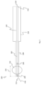
- Figure 1 schematically shows a balloon dilation device 100 having a balloon 102 and a sensor coil (not shown) arranged at the distal end 106 of the balloon dilation device 100.
- the balloon dilation device 100 can be used for dilating a sinus cavity and a Eustachian tube.
- the balloon dilation device 100 comprises a shaft 108, the shaft 108 comprising a hypo tube 110.
- the hypo tube 110 can be made of, e.g., polytetrafluoroethylene (PTFE), steel, or nitinol.
- the hypo tube 110 has an outer diameter of 1.4 mm.
- the balloon dilation device is realised with a hypo tube having an outer diameter of between 1.2 mm and 1.5 mm.
- the hypo tube 110 has a central lumen (not visible) having a diameter of 0.8 mm thus constituting an inner diameter of the hypo tube.
- the balloon dilation device is realised with a hypo tube having an inner diameter of between 0.7 mm and 1.0 mm.
- the shaft can be realized without a central lumen and with the at least one sensor coil, e.g., being embedded into or attached to the shaft, preferably, at or close to the distal end of the balloon dilation device.
- the shaft of the balloon dilation device 100 can be configured the same way as the shafts being described with respect to figures 6 , 7 , 8 , and 9 , thus, having an inner and an outer hypo tube.
- the hypo tube 110 is attached to a handle 112, the handle extending from the proximal end 114 of the balloon dilation device 100 towards the distal end 106 of the balloon dilation device 100.
- the central lumen extends through the handle 112 to an attachment 116 for inserting, e.g., a marker carrier (equipped with one or more sensor coils), a light fibre or a suction tube.
- the handle 112 has a length L1 of 130 mm and a diameter D1 of 19 mm.
- the handle 112 comprises an attachment 118 for attaching a fluid source (not shown) to the balloon dilation device, e.g., via a tube.
- a fluid source not shown
- an inflation lumen extends through the handle 112 and the shaft 108 to a connecting point (not visible) for feeding a fluid into or out of a balloon 102 that is arranged adjacent to the distal end 106 of the balloon dilation device 100.
- the balloon 102 can be inflated by feeding a fluid through the inflation lumen into the balloon 102.
- the balloon 102 can be deflated by feeding a fluid out of the balloon 102 through the inflation lumen.
- the balloon When being inflated, the balloon has a diameter D2 of 6 mm. In other embodiments that are not shown the diameter of the balloon in its inflated state can be different, e.g., the diameter can lie between 3 mm and 10 mm.
- the balloon 102 is fixedly arranged at the shaft 108 and has a length L2 of 18 mm. In various embodiments, however, the balloon can have a different length that, e.g., is between 10 mm and 25 mm, preferably, between 15 mm and 20 mm.
- the shaft 108 has a length L3 of 128 mm. Extending from the distal end 106 of the balloon dilation device 100 towards the proximal end 114 of the balloon dilation device 100, the shaft 108 comprises a malleable tip region 122 having a length L4 of 30 mm. Preferably, the malleable tip region 122 of the shaft 108 is produced by heat treatment of the shaft 108.
- a balloon dilation device having a shaft with a length of 128 mm can also have a malleable tip region having different length, e.g., a length that is between 10 mm and 60 mm, preferably between 20 mm and 50 mm, even more preferably between 25 mm and 35 mm.
- the balloon dilation device can also have a shaft having a different length, e.g., a length of between 1.2 mm and 1.8 mm, preferably between 1.2 mm and 1.6 mm, even more preferably between 1.2 mm and 1.4 mm.
- a balloon dilation device having a shaft with a length of between 1.2 mm and 1.8 mm can also have a malleable tip region extending from the distal end of the balloon dilation device towards the proximal end of the balloon dilation device, the malleable tip region having a length that is between 10 mm and 60 mm.
- position and orientation of the balloon dilation device 100 can be determined with a position detection system (not shown).
- position and orientation of the balloon dilation device 100 can be calculated using a determined position and orientation of the sensor coil. Therefore, the balloon dilation device 100 is exposed to an alternating electromagnetic field such that a current is induced in the sensor coil. The current induced depends on position and orientation of the sensor coil in relation to the alternating electromagnetic field.
- a sensor coil signal is transmitted from the sensor coil to the position detection system, e.g., via a cable connecting the sensor coil to the position detection system.
- the sensor coil signal can be processed by the position detection system to determine position and orientation of the sensor coil. Having calculated position and orientation of the balloon dilation device based on the determined position and orientation of the sensor coil, the position of the balloon dilation device can be displayed in images of a patient for supporting a surgeon in navigating the balloon dilation device inside a human body.
- Figure 2 schematically shows a balloon dilation device 200 in a longitudinal sectional view with a marker carrier 202, the marker carrier 202 comprising two sensor coils 204, 206 that are displaced in longitudinal direction along the shaft 208.
- the marker carrier 202 is arranged in a central lumen 210, the central lumen 210 extending from the distal end 212 of the balloon dilation device 200 to the proximal end 214 of the balloon dilation device 200.
- the marker carrier 202 extends through the full length of the central lumen 210 and can be removed from the lumen through an opening 216 at the proximal end 214 of the balloon dilation device 200, e.g., after having positioned the balloon dilation device 200, e.g., in a sinus cavity. Because the central lumen 210 also has an opening 218 at the distal end of the balloon dilation device 200, after removing the marker carrier 202 the central lumen 210 can be used for suction or irrigation purposes.
- a suction tube can be inserted into the central lumen 210 for drainage of mucus from the paranasal sinuses.
- the central lumen 210 extends through the shaft 208 and through the handle 220 from the distal end 212 of the balloon dilation device 200 to the proximal end 214 of the balloon dilation device 200.
- the shaft can comprise one hypo tube as described with reference to figure 1 or can have an inner and an outer hypo tube as described with reference to figures 5 , 6 , 7 , 8 , or 9 .
- an inflation lumen extends from the proximal end 214 of the balloon dilation device 200 to a connecting point (not shown). At the connecting point the inflation lumen is fluidly connected to a balloon 222 that is arranged at the shaft 208. Through the inflation lumen a fluid can be fed into or out of the balloon for inflating and deflating the balloon 222, respectively.
- the balloon 222 is arranged within a malleable tip region 224 of the shaft 208.
- the shaft can be plastically deformed to facilitate accessing passageways and positioning of the balloon dilation device 200, e.g., in sinus cavities.
- the first sensor coil 204 is arranged at the distal end 212 of the balloon dilation device 200 such that when the shaft is plastically deformed in the malleable tip region 224, e.g., using a shaping tool, the sensor coil 204 is displaced with respect to the rest of the shaft.
- the second sensor coil 206 is arranged at the shaft but adjacent to the malleable tip region 224. Hence, if the shaft 208 is bend in the malleable tip region 224, the second sensor coil 206 is not displaced with respect to the rest of the shaft 208. Position and orientation of the second sensor coil thus represent position and orientation of the part of the shaft that stays unbend. However, when plastically deforming the shaft in the malleable tip region 224, the first 204 sensor coil is displaced with respect to the second sensor coil 206 such that the two sensor coils 204, 206 have a non-zero angle enclosed between their longitudinal axis.
- the degree of bending of the shaft 208 can be calculated from the determined position and orientation of each of the two sensor coils 204, 206.
- the shape of the balloon dilation device in that section of the shaft that lies between the two sensor coils 204, 206 can be reconstructed based on the determined position and orientation of each of the two sensor coils 204, 206.
- the balloon dilation device 200 can be visualized on monitor in its actual shape thus having a bend malleable tip region 224.
- Figure 3 schematically shows a medical system 300 comprising a balloon dilation device 302, the balloon dilation device 302 comprising a sensor coil 304 and a balloon 306.
- the balloon dilation device 302 can be configured the same way as the balloon dilation device described with reference to figure 1 or the balloon dilation device described with reference to figure 2 or the balloon dilation device as described with reference to figure 5 .
- the balloon dilation device 302 is connected to a fluid source 308 via a tube.
- the fluid source is configured for providing a fluid, i.e., a gas or a liquid.
- a fluid is fed into the balloon 306.
- the fluid source 308 comprises an optional fluid sensor 310 for measuring a physical quantity of a fluid that is fed into the balloon.
- the fluid sensor can be an inflation pressure sensor for measuring an inflation pressure or a fluid volume sensor for measuring an amount of fluid that has been fed into or out of the balloon. Also both sensors can be present at the same time.
- the balloon dilation device itself can have one or more fluid sensors.
- These fluid sensor of the balloon dilation device can likewise be an inflation pressure sensor or a fluid volume sensor.
- the balloon dilation device can also comprise a sensor that is configured for directly detecting the shape of the balloon.
- Fluid sensor 310 of the fluid source 308 and, if present, fluid sensors comprised by the balloon dilation device 302 itself are configured for providing fluid sensor signals representing the measured a physical quantity of the fluid.
- Fluid sensor signals representing a measured physical quantity of the fluid can be transmitted to a balloon shape computation unit 312, e.g., via a cable or wireless.
- the balloon shape computation unit 312 is configured for computing the shape of the balloon 306 based on fluid sensor signals provided by the fluid sensor 310 of the fluid source 308. If no fluid sensor 310 for measuring a physical quantity of the fluid is present in the medical system 300, also no balloon shape computation unit 312 needs to be present which is thus an optional element.
- the balloon shape computation unit 312 is connected to a visualization unit 314, the visualization unit 314, preferably, being configured to access and use the computed balloon shape.
- the visualization unit 314 is configured to process the computed balloon shape, in particular, for visualizing the balloon dilation device 302 having a balloon shape as computed by the balloon shape computation unit 308 on a monitor 316.
- the medical system 300 comprises a position detection system 318 for determining position and orientation of the balloon dilation device 302 based on sensor coil signals provided by the sensor coil 304Preferably, the sensor coil 304 is arranged at the shaft of the balloon dilation device 302 at the distal end of the balloon dilation device 302.
- the position detection system 318 can comprise a field generator (not shown) for generating an alternating electromagnetic field.
- the balloon dilation device 302 equipped with the sensor coil 304 is exposed to the alternating electromagnetic field such that a current is induced in the sensor coil 304.
- respective a sensor coil signal can be transmitted to the position detection system 318, e.g., via a cable or wirelessly.
- the position detection system 318 is configured for processing a received sensor coil signal for calculating position and orientation of the balloon dilation device 302. This often includes that position and orientation represented by the sensor coil signal are determined and used together with transformation functions obtained by calibrating the sensor coil to the tip of the balloon dilation device 302 to calculate position and orientation of the balloon dilation device 302 relative to the position detections system 318.
- the position detection system 318 is connected to the visualization unit 314.
- the visualization unit 314 is configured for visualizing a digital representation of at least a part of the balloon dilation device 302, e.g., the balloon dilation device tip, on the monitor 316 based on the position and orientation of the balloon dilation device 302 as determined by the position detection system 318.
- a digital representation of the balloon dilation device 302 is visualized together with images of a patient to support a surgeon in handling the balloon dilation device 302 while guiding the balloon dilation device 302 inside the human body.
- the medical system can comprise an optional device shape reconstruction unit 320.
- the device shape reconstruction unit 320 is connected to the position detection system 318 and to the visualization unit 314.
- the device shape reconstruction unit 320 is configured for reconstructing the shape of the balloon dilation device 302 based on position and orientation of the sensor coil 304 determined by the position detection system 318.
- the device shape reconstruction unit 320 is configured for accessing the determined position and orientation for each sensor coil present in the balloon dilation device 302 and to process the determined positions and orientations of the sensor coils for reconstructing the shape of the balloon dilation device 302.
- the visualization unit 314 is configured for visualizing the balloon dilation device 302 in its reconstructed shape.
- the shape of the balloon dilation device can be reconstructed taking into account a possible bending of the shaft in its malleable tip region.
- Figure 4 shows a flow diagram representing a method for determining position and orientation of a balloon dilation device. The method described in the following can be implemented using a medical system as described with reference to figure 3 .
- the method comprises the steps of
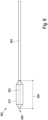
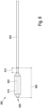
- Figure 5 shows a balloon dilation device 500 comprising a balloon 502, a shaft 504, a handle 506 and at least one sensor coil (not shown).
- the shaft 504 extends from the distal end 508 of the balloon dilation device 500 towards the proximal end 510 of the balloon dilation device 500 and has an inflation lumen (not visible).
- the shaft 504 comprises an inner hypo tube 512 and an outer hypo tube 514.
- the inner hypo tube 512 has an outer diameter that is equal to or smaller than the diameter of a lumen of the outer hypo tube 514.
- the inner hypo tube 512 is at least partly arranged inside the lumen of the outer hypo tube 514. At least with the outer hypo tube 514, the shaft 504 is attached to the handle 506.
- the outer hypo tube 514 does not extend up to the distal end 508 of the balloon dilation device 500 but ends before.
- the inner hypo tube 512 extends up to the distal end 508 of the balloon dilation device 500.
- the total length of the shaft 504 thus is the sum of the lengths of the visible part of the outer hypo tube 514 and the visible part of the inner hypo tube 512.
- the inner hypo tube 512 is completely annealed such that it has an ultimate tensile strength of up to 750 N/mm 2 . That part of the inner hypo tube 512 that extends between the distal end 508 of the balloon dilation device 500 and the distal end of the outer hypo tube 514, i.e., the visible part of the inner hypo tube 512, forms a malleable tip region 516 of the shaft.
- the inflatable balloon 502 is fixedly arranged at the shaft 504, i.e., attached to the inner hypo tube 512 of the shaft 504.
- the balloon 502 has a length that is approximately equal to the length of the malleable tip region 516.
- the balloon 502 itself also deforms accordingly.
- the malleable tip region 516 is formed to have an angle, typically, the balloon 502, too, shows a corresponding bend.
- the balloon 502 is fluidly connected to the inflation lumen of the balloon dilation device 500 such that the balloon 502 can be inflated and deflated by feeding a fluid through the inflation lumen into or out of the balloon 502.
- the fluid for inflating the balloon 502 can be provided by a fluid source (not shown) that is connect to the inflation lumen, e.g., via a tube, at the attachment 518 arranged at the handle 506.
- the inflation lumen thus extends from the attachment 518 through the handle 506 and the shaft 504 to a connecting point (not visible) for feeding a fluid into or out of a balloon 502.
- the balloon dilation device 500 comprises a central lumen (not visible).
- the central lumen extends from an opening of the inner hypo tube 512 at the distal end 508 of the balloon dilation device 500 to an attachment 520 that is arranged at the handle 506.
- the central lumen can extend from the attachment 520 through the handle 506 and the shaft and end before the distal end 508 of the balloon dilation device 500.
- the shaft can be closed at the distal end 508 of the balloon dilation device 500, i.e., in this case no opening is present at the distal end 508 of the balloon dilation device 500.
- At least one sensor coil (not shown) is arranged that is configured for capturing an electromagnetic field and for providing a sensor coil signal representing position and orientation of the sensor coil.
- the balloon dilation device 500 can be connected to a position detection system that is configured for determining position and orientation of the balloon dilation device 500 in an electromagnetic field.
- the at least one sensor coil can also be comprised in a marker carrier that is arranged inside the central lumen of the balloon dilation device 500.
- a marker carrier comprising, e.g., two sensor coils can be inserted into the central lumen to be removably arranged inside the central lumen.
- a marker carrier comprises at least one sensor coil that is configured for capturing an electromagnetic field
- position and orientation of the sensor coil can be determined with an electromagnetic position detection system.
- the at least one sensor coil of a marker carrier can be used to connect the balloon dilation device 500 to a position detection system in order to track the position of the balloon dilation device 500.
- By connecting the balloon dilation device 500 to a position detection system it is possible to display the position of the balloon dilation device 500 in sectional images of a model of a patient in order to assist a surgeon in navigating the balloon dilation device 500.
- the marker carrier can be arranged removably inside the central lumen, after having positioned the balloon dilation device 500 in a cavity, the marker carrier can be removed from the central lumen and, e g., a suction tube can be inserted into the central lumen.
- a marker carrier comprising sensor coils is arranged inside the central lumen
- one sensor coil is arranged at the distal end 508 of the at least balloon dilation device 500 and a second coil is arranged adjacent to the malleable tip region 516, i.e., in that part of the shaft 504 in which the outer hypo tube 514 is present.
- the sensor coils of the marker carrier are arranged inside the central lumen such that, if the malleable tip region of the shaft is deformed plastically, a non-zero angle is enclosed between the longitudinal axis of the two coils.
- Figure 6 shows a shaft 600 that has an inner hypo tube 602 and an outer hypo tube 504.
- the shaft 600 can be attached to a handle (not shown) of a balloon dilation device, e.g., of a balloon dilation device as described with respect to figure 1 or of a balloon dilation device as described with respect to figure 5 .
- the inner hypo tube 602 is completely annealed.
- the outer hypo tube 604 is configured such that it does not plastically deform if an external force of a magnitude typically acting on the shaft during surgery is exerted on the outer hypo tube 604.
- the inner hypo tube 602 is at least partly arranged inside a lumen of the outer hypo tube 604.
- the outer hypo tube 604 ends before the distal end 606 of the shaft 600.
- the inner hypo tube 602 extends up to the distal end 606 of the shaft 600 such that the shaft's total length is the sum of the visible parts of the inner hypo tube 602 and the outer hypo tube 604.
- That part of the inner hypo tube 602 that extends from the distal end of the outer hypo tube 604 to the distal end 606 of the shaft 600 forms a malleable tip region 608 of the shaft 600.
- the shaft in the malleable tip region 608, can be plastically deformed, e.g., using a shaping tool. It is preferred that prior surgery, the shaft in its malleable tip region 608 is plastically deformed so that the shape of the shaft is suitable for a specific procedure to be carried out with a balloon dilation device.
- the shaft 600 can be plastically deformed to have a specifically selected angle with respect to the rest of the shaft, i.e., with respect to the outer hypo tube 604.
- a shaping tool can be used having several pre-fixed shape positions that are suitable, e.g., for accessing a particular cavity.
- the balloon 610 Fixed to the shaft 600 in the malleable tip region 608 there is an inflatable balloon 610.
- the balloon 610 has a length that corresponds to the length of the malleable tip region 608.
- the balloon 610 is fluidly connected to the inflation lumen (not visible) of the shaft 600 such that the balloon 610 can be inflated and deflated by feeding a fluid through the inflation lumen into or out of the balloon 600.
- At the shaft 600 at least one sensor coil (not visible) is arranged, the at least one sensor coil being configured for capturing an electromagnetic field and for providing a sensor coil signal representing position and orientation of the sensor coil in an electromagnetic field.
- the shaft 600 can comprise two sensor coils that are arranged at the shaft 600 as described with reference to figure 7 .
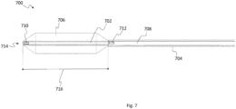
- a shaft 700 is shown in a longitudinal sectional view, the shaft 700 having an inner hypo tube 702 and an outer hypo tube 704 that are arranged and configured as described with reference to figure 6 . Also as described with reference to figure 6 there is a balloon 706 fixedly arranged at the shaft 700.
- the shaft 700 has a central lumen 708 and an inflation lumen (not visible).
- two sensor coils 710, 712 are arranged in the central lumen 708 in the central lumen 708 .
- the first sensor coil 710 is arranged at the distal end 714 of the shaft 700 and the second sensor coil 712 is arranged adjacent to the malleable tip region 716 of the shaft 700. If the malleable tip region 716 is plastically deformed to have an angle with respect to the rest of the shaft 700, preferably, the two sensor coils are displaced such that their longitudinal axis enclose a non-zero angle.
- Each of the sensor coils 710, 712 is connected to electrical wiring (not shown) running from the respective sensor coil 710, 712 towards a proximal end of the shaft 700.
- the electrical wiring run up to an electrical connection of the balloon dilation device at which the electrical wiring can be connected to a cable for connecting the balloon dilation device to a position detection system.
- sensor coil signals provided by the sensor coils 710, 712 can be transmitted to a position detection system that is configured for determining position and orientation of each of the sensor coils 710, 712 by analysing respective sensor coil signals. Based on determined position and orientation of the two sensor coils it is possible to determine the bending of the shaft 700 and to reconstruct the actual shape of the shaft 700 in case the malleable tip region 716 of the shaft 700 is plastically shaped.
- the sensor coils 710, 712 can be part of a marker carrier that is removably arranged inside the central lumen 708 of the shaft 700 to connect a balloon dilation device to a position detection system.
- the shaft comprises only one of the sensor coils 710, 712 or additional sensor coils that are distributed along the length of the shaft.
- a shaft 800 is shown having a completely annealed inner hypo tube 802 and an outer hypo tube 804.
- the outer hypo tube 804 is configured such that it does not plastically deform if an external force of a magnitude typically acting on the shaft 800 during surgery is exerted on the outer hypo tube 804.
- the shaft 800 can be attached to a handle (not shown) of a balloon dilation device, e.g., of a balloon dilation device as described with reference to figure 1 or of a balloon dilation device as described with reference to figure 5 .
- the inner hypo tube 802 is arranged at least partly in a lumen of the outer hypo tube 804.
- the outer hypo tube 804 ends before the distal end 806 of the shaft 800.
- the completely annealed inner hypo tube 802 extends up to the distal end 806 of the shaft 800 and that part of the inner hypo tube 802 that extends from the distal end of the outer hypo tube 804 to the distal end 806 of the shaft 800 forms the malleable tip region 808 of the shaft 800.
- a balloon 810 is fixedly arranged at the shaft 800.
- the balloon 810 is fluidly connected to the inflation lumen (not visible) of the shaft 800 such that the balloon 810 can be inflated and deflated by feeding a fluid through the inflation lumen into or out of the balloon 800.
- the balloon 810 is arranged adjacent to the distal end 806 of the shaft and has a length that is smaller than the length of the malleable tip region.
- the proximal end of the balloon 810 ends before proximal end of the malleable tip region 808 such that there is an exposed section 812 of the inner hypo tube 802 in which no balloon 810 is arranged.
- this exposed section 812 of the inner hypo tube 802 forms a bending section in which the malleable tip region 808 can be plastically deformed several times for shaping the malleable tip region 808.
- the malleable tip region 808 is deformed in the exposed section 812 such that the malleable tip region 808 has an angle to the rest of the shaft 800, i.e., to the outer hypo tube 804, the remaining part of the malleable tip region 808 in which the balloon 810 is arranged can maintain its shape.
- the balloon 810 itself is not mechanically stressed by shaping the malleable tip region 808 and can maintain its balloon shape.
- At the shaft 800 at least one sensor coil (not visible) is arranged.
- the shaft 800 can comprise two sensor coils that are arranged at the shaft 800 as described with reference to figure 9 .
- Figure 9 shows a shaft 900 in a longitudinal sectional view, the shaft 900 having a completely annealed inner hypo tube 902 and an outer hypo tube 904 that are arranged and configured as described with reference to figure 8 .
- the shaft 900 has a central lumen 906 and an inflation lumen (not visible).
- two sensor coils 908, 910 are arranged such that a first coil 908 is arranged at the distal end 912 of the shaft 900 and a second coil 910 is arranged adjacent to the malleable tip region 914.
- the two sensor coils 908, 910 are connected to electrical wiring (not shown) for connecting the two sensor coils 908, 910 to a position detection system. From sensor coil signals provided by the sensor coils 908, 910, position and orientation of each of the sensor coils can be determined with a connected position detection system.
- a balloon 916 is fixedly arranged at the shaft 900 and fluidly connected to the inflation lumen such that the balloon 916 can be inflated and deflated by feeding a fluid through the inflation lumen into or out of the balloon 916.
- the balloon 912 is arranged adjacent to the distal end 912 of the shaft 900 and ends before the distal end of the outer hypo tube 904.
- a section 918 of the inner hypo tube 902 that extends between the proximal end of the balloon 916 and the proximal end of the malleable tip region 914 is exposed, i.e., is visible from outside.
- the shaft can be plastically deformed to shape the malleable tip region 914 to have an angle to the rest of the shaft 900.
Claims (13)
- Un dispositif de dilatation par ballonnet (200) ayant une extrémité distale (212) et une extrémité proximale (214), ledit dispositif de dilatation par ballonnet (200) comprenant- une poignée (220), s'étendant de l'extrémité proximale (214) du dispositif de dilatation par ballonnet (200) vers l'extrémité distale (212) du dispositif de dilatation par ballonnet (100),- une tige (208), s'étendant de l'extrémité distale (212) du dispositif de dilatation par ballonnet (200) vers l'extrémité proximale (214) du dispositif de dilatation par ballonnet (200), ladite tige (208) ayant une lumière de gonflage,- un ballonnet gonflable (222), disposé de manière fixe sur la tige (208), dans lequel le ballon est relié de manière fluide à la lumière de gonflage de sorte que le ballon peut être gonflé et dégonflé en faisant entrer ou sortir un fluide par la lumière de gonflage, et- au moins une bobine de capteur (204) disposée sur la tige (208), dans laquelle au moins une bobine de capteur (204) est configurée pour capturer un champ électromagnétique et pour fournir un signal de bobine de capteur représentant la position et l'orientation de la bobine de capteur (204),dans lequelle dispositif de dilatation du ballonnet (200) comprend une deuxième bobine de capteur (206) disposée sur la tige (208), la deuxième bobine de capteur (206) étant déplacée à une certaine distance dans la direction longitudinale par rapport à la au moins une bobine de capteur (204, 206),la tige (208) comporte une zone de pointe malléable (224) s'étendant de l'extrémité distale (212) du dispositif de dilatation par ballonnet (200) vers l'extrémité proximale (214) du dispositif de dilatation par ballonnet (200), caractérisé par le fait quel'au moins une bobine de capteur (204) est disposée- à l'extrémité distale (212) de la tige (208) ou au moins à proximité de celle-ci- dans la zone de la pointe malléable (224),et en ce quela deuxième bobine du capteur (206) est disposée sur la tige (208) à côté de la zone de la pointe malléable (224).
- Le dispositif de dilatation par ballonnet (200) de la revendication 1, dans lequel le ballonnet gonflable (222) est disposé de manière fixe sur la tige (208) dans la région de la pointe malléable (224).
- Le dispositif de dilatation par ballonnet (200) d'au moins une des revendications 1 à 2, comportant une lumière centrale (210) s'étendant de l'extrémité distale (212) du dispositif de dilatation par ballonnet (200) vers l'extrémité proximale (214) du dispositif de dilatation par ballonnet (200), la lumière centrale (210) ayant une ouverture distale à l'extrémité distale (212) du dispositif de dilatation par ballonnet (200) et une ouverture proximale à l'extrémité proximale (214) du dispositif de dilatation par ballonnet (200).
- Le dispositif de dilatation par ballonnet (200) de la revendication 3, comprenant un support de marqueur (202) qui est disposé de manière amovible à l'intérieur et s'étend sur la longueur de la lumière centrale (210), dans lequel le support de marqueur (202) comprend au moins une bobine de capteur (204, 206).
- Le dispositif de dilatation par ballonnet (200) d'au moins une des revendications 2 à 4, dans lequel la région de la pointe malléable (224) a une longueur comprise entre 10 mm et 60 mm, de préférence entre 20 mm et 50 mm, encore plus préférentiellement entre 25 mm et 35 mm, par exemple 30 mm.
- Le dispositif de dilatation par ballonnet (200) d'au moins une des revendications 2 à 5, dans lequel, dans la région de la pointe malléable (224), la tige (208) est faite d'un matériau ayant une résistance à la traction ultime allant jusqu'à 720 Nmm-2.
- Un système médical (300) comprenant- le dispositif de dilatation par ballonnet (302) de l'une des revendications 1 à 6,- un système de détection de position (318), pour déterminer la position et l'orientation du dispositif de dilatation du ballonnet (302) sur la base des signaux de la bobine du capteur fournis par au moins une bobine du capteur (304) du dispositif de dilatation du ballonnet (302),- une source de fluide (308), fixée au dispositif de dilatation du ballonnet (302) pour alimenter le ballonnet en fluide, et- une unité de visualisation (314) pour visualiser au moins une partie du dispositif de dilatation du ballonnet (302) sur un moniteur (316) en fonction de la position et de l'orientation déterminées du dispositif de dilatation du ballonnet (302).
- Le système médical (300) de la revendication 7, comprenant- une unité de reconstruction de la forme du dispositif (320), pour reconstruire la forme du dispositif de dilatation du ballonnet (302) sur la base de la position et de l'orientation du dispositif de dilatation du ballonnet (302) déterminées par le système de détection de la position (318),l'unité de visualisation (314) est configurée pour visualiser le dispositif de dilatation par ballonnet (302) dans sa forme reconstruite.
- Le système médical (300) de la revendication 7 ou 8, dans lequel la source de fluide (308) comprend au moins un capteur de fluide (310) pour mesurer une quantité physique d'un fluide fourni par la source de fluide (308) et pour fournir des signaux de capteur de fluide représentant la quantité physique mesurée et dans lequel le système médical (300) comprend- une unité de calcul de la forme du ballon (312), configurée pour calculer la forme du ballon sur la base des signaux du capteur de fluide fournis par au moins un capteur de fluide (310) de la source de fluide (308),l'unité de visualisation (314) est configurée pour visualiser le dispositif de dilatation du ballonnet (302) ayant une forme de ballonnet telle que calculée par l'unité de calcul de la forme du ballonnet (312).
- Méthode de détermination de la position et de l'orientation d'un dispositif de dilatation par ballonnet selon les revendications 1 à 6, la méthode comprenant les étapes suivantes- générer un champ électromagnétique (S1),- exposer le dispositif de dilatation du ballon au champ électromagnétique, le dispositif de dilatation du ballon ayant une tige, un ballon gonflable disposé de manière fixe sur la tige et au moins une bobine de capteur (S2),- détection de la position et de l'orientation d'au moins une bobine de capteur (S3),- déterminer la position et l'orientation du dispositif de dilatation du ballonnet en fonction de la position et de l'orientation détectées de l'au moins une bobine de capteur (S4), et- visualiser au moins une partie du dispositif de dilatation du ballonnet sur un moniteur en fonction de la position et de l'orientation déterminées du dispositif de dilatation du ballonnet (S5).
- La méthode de la revendication 10, comprenant les étapes suivantes- déterminer la forme d'au moins une partie du dispositif de dilatation du ballonnet en fonction de la position et de l'orientation détectées de l'au moins une bobine de capteur et en fonction de la position et de l'orientation d'une deuxième bobine de capteur disposée sur une tige du dispositif de dilatation du ballonnet, la deuxième bobine de capteur étant déplacée à une certaine distance dans la direction longitudinale par rapport à l'au moins une bobine de capteur, et- visualiser le dispositif de dilatation du ballon dans une forme déterminée en fonction de la position et de l'orientation d'au moins une bobine de capteur et de la seconde bobine de capteur.
- La méthode de la revendication 10 ou 11, comprenant l'étape suivante- Visualisation de la forme du ballon en fonction de la pression de gonflage appliquée et/ou de la quantité de liquide introduite dans le ballon.
- La méthode d'au moins une des revendications 10 à 12, comprenant l'étape suivante- visualiser un aperçu du ballon gonflé avant de le gonfler réellement, en fonction de la position et de l'orientation déterminées du dispositif de dilatation du ballon.
Priority Applications (11)
| Application Number | Priority Date | Filing Date | Title |
|---|---|---|---|
| CA3138386A CA3138386A1 (fr) | 2019-05-02 | 2020-04-30 | Dispositif de dilatation de ballonnet |
| JP2021564754A JP2022530554A (ja) | 2019-05-02 | 2020-04-30 | バルーン拡張デバイス |
| EA202193001A EA202193001A1 (ru) | 2019-05-02 | 2020-04-30 | Устройство баллонной дилатации |
| AU2020264747A AU2020264747A1 (en) | 2019-05-02 | 2020-04-30 | Balloon dilation device |
| CN202080033111.6A CN113811240A (zh) | 2019-05-02 | 2020-04-30 | 球囊扩张装置 |
| SG11202110934WA SG11202110934WA (en) | 2019-05-02 | 2020-04-30 | Balloon dilation device |
| PCT/EP2020/062083 WO2020221882A1 (fr) | 2019-05-02 | 2020-04-30 | Dispositif de dilatation de ballonnet |
| KR1020217037827A KR20220005027A (ko) | 2019-05-02 | 2020-04-30 | 풍선 확장 장치 |
| EP20724041.7A EP3962355A1 (fr) | 2019-05-02 | 2020-04-30 | Dispositif de dilatation de ballonnet |
| IL287657A IL287657A (en) | 2019-05-02 | 2021-10-28 | Balloon dilation device |
| US17/516,580 US20220047854A1 (en) | 2019-05-02 | 2021-11-01 | Balloon dilation device |
Applications Claiming Priority (1)
| Application Number | Priority Date | Filing Date | Title |
|---|---|---|---|
| US201962844922P | 2019-05-08 | 2019-05-08 |
Publications (2)
| Publication Number | Publication Date |
|---|---|
| EP3735898A1 EP3735898A1 (fr) | 2020-11-11 |
| EP3735898B1 true EP3735898B1 (fr) | 2024-03-13 |
Family
ID=67659322
Family Applications (1)
| Application Number | Title | Priority Date | Filing Date |
|---|---|---|---|
| EP19192372.1A Active EP3735898B1 (fr) | 2019-05-02 | 2019-08-19 | Dispositif de dilatation à ballonnet |
Country Status (2)
| Country | Link |
|---|---|
| EP (1) | EP3735898B1 (fr) |
| WO (1) | WO2020221882A1 (fr) |
Families Citing this family (2)
| Publication number | Priority date | Publication date | Assignee | Title |
|---|---|---|---|---|
| US10322269B1 (en) | 2015-01-19 | 2019-06-18 | Dalent, LLC | Dilator device |
| US11672959B2 (en) | 2019-01-18 | 2023-06-13 | Intersect Ent, Inc. | Expandable member systems and methods for drug delivery |
Family Cites Families (9)
| Publication number | Priority date | Publication date | Assignee | Title |
|---|---|---|---|---|
| US7720521B2 (en) * | 2004-04-21 | 2010-05-18 | Acclarent, Inc. | Methods and devices for performing procedures within the ear, nose, throat and paranasal sinuses |
| WO2008042347A2 (fr) * | 2006-10-02 | 2008-04-10 | President And Fellows Of Harvard College | Cathéter à ballonnet intelligent |
| US20100274188A1 (en) | 2007-12-20 | 2010-10-28 | Acclarent, Inc. | Method and System for Treating Target Tissue Within the Eustachian Tube |
| US8834513B2 (en) | 2009-06-05 | 2014-09-16 | Entellus Medical, Inc. | Method and articles for treating the sinus system |
| US9486614B2 (en) | 2011-06-29 | 2016-11-08 | Entellus Medical, Inc. | Sinus dilation catheter |
| US20130274715A1 (en) | 2012-04-13 | 2013-10-17 | Acclarent, Inc. | Method and System for Eustachian Tube Dilation |
| US11478304B2 (en) * | 2015-03-31 | 2022-10-25 | Medtronic Navigation, Inc. | Flexible circuit coils |
| US10321913B2 (en) * | 2016-08-04 | 2019-06-18 | Biosense Webster (Israel) Ltd. | Balloon positioning in a sinuplasty procedure |
| US20180344202A1 (en) * | 2017-05-30 | 2018-12-06 | Biosense Webster (Israel) Ltd. | Catheter Splines as Location Sensors |
-
2019
- 2019-08-19 EP EP19192372.1A patent/EP3735898B1/fr active Active
-
2020
- 2020-04-30 WO PCT/EP2020/062083 patent/WO2020221882A1/fr unknown
Also Published As
| Publication number | Publication date |
|---|---|
| EP3735898A1 (fr) | 2020-11-11 |
| WO2020221882A1 (fr) | 2020-11-05 |
Similar Documents
| Publication | Publication Date | Title |
|---|---|---|
| US10842978B2 (en) | Catheters with non-removable guide members useable for treatment of sinusitis | |
| US10363402B2 (en) | Sinus dilation catheter | |
| US11020136B2 (en) | Deflectable guide catheters and related methods | |
| KR102213571B1 (ko) | 부비강 확장 시스템 및 방법 | |
| US20220047854A1 (en) | Balloon dilation device | |
| JP5848347B2 (ja) | 医療器具のための取り外し可能なナビゲーションシステムおよび方法 | |
| EP3735898B1 (fr) | Dispositif de dilatation à ballonnet | |
| US20150151095A1 (en) | Combined balloon dilation catheter and introducer for dilation of eustachian tube | |
| US8585680B2 (en) | Endovascular device tip assembly incorporating a marker device and method for making the same | |
| US20130281778A1 (en) | Treatment instrument for medical use and method | |
| CN111388841B (zh) | 具有球囊的耳鼻喉(ent)中空导丝 | |
| US20190274886A1 (en) | Device, system and method for treating a eustachian tube | |
| CN218923534U (zh) | 可调弯医用装置 | |
| WO2018146694A1 (fr) | Cathéter de sinuplastie | |
| CN117100982A (zh) | 介入手术用辅助通血导管、组件及医疗装置 |
Legal Events
| Date | Code | Title | Description |
|---|---|---|---|
| PUAI | Public reference made under article 153(3) epc to a published international application that has entered the european phase |
Free format text: ORIGINAL CODE: 0009012 |
|
| STAA | Information on the status of an ep patent application or granted ep patent |
Free format text: STATUS: THE APPLICATION HAS BEEN PUBLISHED |
|
| AK | Designated contracting states |
Kind code of ref document: A1 Designated state(s): AL AT BE BG CH CY CZ DE DK EE ES FI FR GB GR HR HU IE IS IT LI LT LU LV MC MK MT NL NO PL PT RO RS SE SI SK SM TR |
|
| AX | Request for extension of the european patent |
Extension state: BA ME |
|
| STAA | Information on the status of an ep patent application or granted ep patent |
Free format text: STATUS: REQUEST FOR EXAMINATION WAS MADE |
|
| 17P | Request for examination filed |
Effective date: 20210511 |
|
| RBV | Designated contracting states (corrected) |
Designated state(s): AL AT BE BG CH CY CZ DE DK EE ES FI FR GB GR HR HU IE IS IT LI LT LU LV MC MK MT NL NO PL PT RO RS SE SI SK SM TR |
|
| RAP3 | Party data changed (applicant data changed or rights of an application transferred) |
Owner name: INTERSECT ENT INTERNATIONAL GMBH |
|
| STAA | Information on the status of an ep patent application or granted ep patent |
Free format text: STATUS: EXAMINATION IS IN PROGRESS |
|
| 17Q | First examination report despatched |
Effective date: 20220824 |
|
| GRAP | Despatch of communication of intention to grant a patent |
Free format text: ORIGINAL CODE: EPIDOSNIGR1 |
|
| STAA | Information on the status of an ep patent application or granted ep patent |
Free format text: STATUS: GRANT OF PATENT IS INTENDED |
|
| INTG | Intention to grant announced |
Effective date: 20230913 |
|
| RIN1 | Information on inventor provided before grant (corrected) |
Inventor name: NORMAN, NICHOLAS Inventor name: DESINGER, KAI Inventor name: MUCHA, DIRK |
|
| GRAS | Grant fee paid |
Free format text: ORIGINAL CODE: EPIDOSNIGR3 |
|
| GRAA | (expected) grant |
Free format text: ORIGINAL CODE: 0009210 |
|
| STAA | Information on the status of an ep patent application or granted ep patent |
Free format text: STATUS: THE PATENT HAS BEEN GRANTED |
|
| RAP1 | Party data changed (applicant data changed or rights of an application transferred) |
Owner name: FIAGON GMBH |
|
| AK | Designated contracting states |
Kind code of ref document: B1 Designated state(s): AL AT BE BG CH CY CZ DE DK EE ES FI FR GB GR HR HU IE IS IT LI LT LU LV MC MK MT NL NO PL PT RO RS SE SI SK SM TR |
|
| REG | Reference to a national code |
Ref country code: GB Ref legal event code: FG4D |
|
| REG | Reference to a national code |
Ref country code: CH Ref legal event code: EP |
|
| REG | Reference to a national code |
Ref country code: DE Ref legal event code: R096 Ref document number: 602019048114 Country of ref document: DE |