EP3735809B1 - Mounting assembly for plough skimmers - Google Patents
Mounting assembly for plough skimmers Download PDFInfo
- Publication number
- EP3735809B1 EP3735809B1 EP19173026.6A EP19173026A EP3735809B1 EP 3735809 B1 EP3735809 B1 EP 3735809B1 EP 19173026 A EP19173026 A EP 19173026A EP 3735809 B1 EP3735809 B1 EP 3735809B1
- Authority
- EP
- European Patent Office
- Prior art keywords
- mounting rail
- skimmer
- support bracket
- mounting
- plough
- Prior art date
- Legal status (The legal status is an assumption and is not a legal conclusion. Google has not performed a legal analysis and makes no representation as to the accuracy of the status listed.)
- Active
Links
- 241000238634 Libellulidae Species 0.000 title description 218
- 230000013011 mating Effects 0.000 claims description 60
- 238000000034 method Methods 0.000 claims description 11
- 238000004519 manufacturing process Methods 0.000 claims description 7
- 239000002689 soil Substances 0.000 description 29
- 230000002441 reversible effect Effects 0.000 description 9
- 230000000694 effects Effects 0.000 description 7
- 238000003971 tillage Methods 0.000 description 7
- 241000196324 Embryophyta Species 0.000 description 6
- 125000006850 spacer group Chemical group 0.000 description 5
- 238000000429 assembly Methods 0.000 description 4
- 230000000712 assembly Effects 0.000 description 4
- 238000003466 welding Methods 0.000 description 4
- 238000005304 joining Methods 0.000 description 3
- 238000002360 preparation method Methods 0.000 description 3
- 238000004026 adhesive bonding Methods 0.000 description 2
- 238000004891 communication Methods 0.000 description 2
- 238000010586 diagram Methods 0.000 description 2
- 235000015097 nutrients Nutrition 0.000 description 2
- 230000003068 static effect Effects 0.000 description 2
- 239000004575 stone Substances 0.000 description 2
- 241000189524 Baccharis halimifolia Species 0.000 description 1
- 241000699670 Mus sp. Species 0.000 description 1
- 241000607479 Yersinia pestis Species 0.000 description 1
- 238000005273 aeration Methods 0.000 description 1
- 238000003491 array Methods 0.000 description 1
- 238000005056 compaction Methods 0.000 description 1
- 238000000151 deposition Methods 0.000 description 1
- 201000010099 disease Diseases 0.000 description 1
- 208000037265 diseases, disorders, signs and symptoms Diseases 0.000 description 1
- 238000009313 farming Methods 0.000 description 1
- 210000003608 fece Anatomy 0.000 description 1
- 230000035558 fertility Effects 0.000 description 1
- 238000001914 filtration Methods 0.000 description 1
- 230000012010 growth Effects 0.000 description 1
- 238000003306 harvesting Methods 0.000 description 1
- 238000003973 irrigation Methods 0.000 description 1
- 230000002262 irrigation Effects 0.000 description 1
- 239000010871 livestock manure Substances 0.000 description 1
- 230000007774 longterm Effects 0.000 description 1
- 230000014759 maintenance of location Effects 0.000 description 1
- 230000000149 penetrating effect Effects 0.000 description 1
- 230000035515 penetration Effects 0.000 description 1
- 230000008635 plant growth Effects 0.000 description 1
- 239000010908 plant waste Substances 0.000 description 1
- 239000011435 rock Substances 0.000 description 1
- 230000002786 root growth Effects 0.000 description 1
- 239000007787 solid Substances 0.000 description 1
- 238000009331 sowing Methods 0.000 description 1
- XLYOFNOQVPJJNP-UHFFFAOYSA-N water Substances O XLYOFNOQVPJJNP-UHFFFAOYSA-N 0.000 description 1
Images


Classifications
-
- A—HUMAN NECESSITIES
- A01—AGRICULTURE; FORESTRY; ANIMAL HUSBANDRY; HUNTING; TRAPPING; FISHING
- A01B—SOIL WORKING IN AGRICULTURE OR FORESTRY; PARTS, DETAILS, OR ACCESSORIES OF AGRICULTURAL MACHINES OR IMPLEMENTS, IN GENERAL
- A01B15/00—Elements, tools, or details of ploughs
- A01B15/14—Frames
-
- A—HUMAN NECESSITIES
- A01—AGRICULTURE; FORESTRY; ANIMAL HUSBANDRY; HUNTING; TRAPPING; FISHING
- A01B—SOIL WORKING IN AGRICULTURE OR FORESTRY; PARTS, DETAILS, OR ACCESSORIES OF AGRICULTURAL MACHINES OR IMPLEMENTS, IN GENERAL
- A01B17/00—Ploughs with special additional arrangements, e.g. means for putting manure under the soil, clod-crushers ; Means for breaking the subsoil
- A01B17/002—Means for putting manure, debris, straw or the like under the soil
-
- A—HUMAN NECESSITIES
- A01—AGRICULTURE; FORESTRY; ANIMAL HUSBANDRY; HUNTING; TRAPPING; FISHING
- A01B—SOIL WORKING IN AGRICULTURE OR FORESTRY; PARTS, DETAILS, OR ACCESSORIES OF AGRICULTURAL MACHINES OR IMPLEMENTS, IN GENERAL
- A01B15/00—Elements, tools, or details of ploughs
- A01B15/18—Coulters
-
- A—HUMAN NECESSITIES
- A01—AGRICULTURE; FORESTRY; ANIMAL HUSBANDRY; HUNTING; TRAPPING; FISHING
- A01B—SOIL WORKING IN AGRICULTURE OR FORESTRY; PARTS, DETAILS, OR ACCESSORIES OF AGRICULTURAL MACHINES OR IMPLEMENTS, IN GENERAL
- A01B3/00—Ploughs with fixed plough-shares
- A01B3/24—Tractor-drawn ploughs
- A01B3/26—Tractor-drawn ploughs without alternating possibility
-
- A—HUMAN NECESSITIES
- A01—AGRICULTURE; FORESTRY; ANIMAL HUSBANDRY; HUNTING; TRAPPING; FISHING
- A01B—SOIL WORKING IN AGRICULTURE OR FORESTRY; PARTS, DETAILS, OR ACCESSORIES OF AGRICULTURAL MACHINES OR IMPLEMENTS, IN GENERAL
- A01B3/00—Ploughs with fixed plough-shares
- A01B3/46—Ploughs supported partly by tractor and partly by their own wheels
- A01B3/462—Alternating ploughs with frame rotating about a vertical axis
-
- A—HUMAN NECESSITIES
- A01—AGRICULTURE; FORESTRY; ANIMAL HUSBANDRY; HUNTING; TRAPPING; FISHING
- A01B—SOIL WORKING IN AGRICULTURE OR FORESTRY; PARTS, DETAILS, OR ACCESSORIES OF AGRICULTURAL MACHINES OR IMPLEMENTS, IN GENERAL
- A01B3/00—Ploughs with fixed plough-shares
- A01B3/36—Ploughs mounted on tractors
- A01B3/40—Alternating ploughs
- A01B3/42—Turn-wrest ploughs
Definitions
- the present disclosure relates to a mounting assembly for agricultural vehicles, particularly a mounting assembly for ground engaging parts of agricultural implements.
- a mounting assembly for a plough skimmer there is provided a mounting assembly for a plough skimmer.
- Another aspect relates to a method for manufacturing such mounting assemblies.
- land preparation In agriculture, farming cycles are followed that can roughly be divided into the different steps of land preparation, seed sowing, fertilizing, irrigation, crop growth, and harvesting. Each of these steps is critical to yield optimal crop results and achieve the desired returns on initial investments.
- land preparation is typically further divided into steps of, as necessary, clearing obstructions (e.g. bushes, stones and rocks) and subsequent tillage.
- Tillage can be separated into primary (relatively deep) and secondary (relatively shallow) tillage.
- primary tillage such as ploughing
- the soil is turned over such that nutrients come to the surface.
- this process also aerates the earth - enabling it to hold more moisture.
- Secondary tillage e.g. seedbed cultivation
- the turnplough also known as the mouldboard plough
- the mouldboard plough includes a variety of plough bodies, which are blades for penetrating and turning over the soil in arrays of adjacent trenches, known as furrows.
- Modern ploughs typically include a plurality of plough bodies connected to a plough frame such that they are laterally offset manner from each other when the plough is in use.
- Each plough body is connected to the plough frame via corresponding beams.
- the plough frame is connected to a towing or pushing vehicle via a hitch arranged at a front or back end of the frame.
- plough skimmers In addition to the plough bodies, it is known to use so-called "plough skimmers". Typically, one skimmer is placed in front of every plough body. The purpose of the plough skimmers is primarily to cut a shallow layer off the top of the ground surface before the latter is turned over by the plough bodies. The use of plough skimmers results in a more even ploughing result and reduces the amount of plant residues left on the ground surface after ploughing. Accordingly, the use of skimmers further reduces the possibility of inadvertent plant growth in ploughed fields.
- the skimmer depth is typically adjustable to ensure that the skimmers can be placed in the correct working depth.
- skimmers are typically arranged up to 10cm below the ground surface. Arranging the skimmers in a position that is significantly higher or lower than this may reduce the quality of the ploughing result.
- a mounting bracket holds a shaft (or rail) that is connected to the skimmer.
- the skimmer shaft runs within the mounting bracket and may be fixed with respect to the bracket by tightening one or more threaded bolts against an outer surface of the shaft.
- the threaded bolts are loosened, and the shaft can be moved up and down with respect to the bracket. Once the depth is adjusted, the bolt is again tightened to fix the skimmer shaft in place. Adjusting the depth with this arrangement usually requires one or more tools to loosen and/or tighten the bolts.
- a tool-free solution is a skimmer mount type that utilises a pin interlocking the mounting bracket with the shaft to set the depth. To adjust the depth, the pin is removed, thereby allowing movement between the skimmer shaft and the mounting bracket. Once the desired depth is reached, the pin is reinserted in a new position along the shaft.
- this second solution requires no tools for depth adjustment, the connection between the mounting bracket and the skimmer shaft can exhibit significant play, leading to vibrating movements and thus wear between the mounting bracket and the skimmer shaft.
- DE 7415663 U discloses a skimmer support bracket in which a collar-like first part surrounds a support member in the form of a rod having a flattened portion against which a section of the interior of the first part bears in use.
- a bolt extends through a threaded hole in the first part to engage the rod and secure the skimmer to the rod.
- a mounting assembly for a plough skimmer comprising a mounting rail configured to be connected to the main frame of a plough and a skimmer support bracket adapted to connect a plough skimmer to the mounting rail.
- the skimmer support bracket is adapted to surround parts of the mounting rail, the mounting rail and the skimmer support bracket having aligned mating surfaces that are arranged obliquely to a ploughing direction such that the mounting rail and the skimmer support bracket are braced against each other in at least two directions when the plough skimmer is in use and wherein the skimmer support bracket is a two-piece structure comprising a first part for connection with a first side of the mounting rail and a second part for connection with an opposite, second side of the mounting rail, the mounting assembly being characterised in that the first and second parts of the skimmer support bracket are permanently connected to each other.
- a first force vector acts to brace the mounting rail and the skimmer support bracket against each other in a direction that is perpendicular to the mating surfaces.
- a second force vector acts to brace the mounting rail and the skimmer support bracket against each other in a direction that is parallel with the mating surfaces. Arranging the mounting rail and the skimmer support bracket such that they are braced against each other in more than one direction will result in a self-locking connection between the mounting rail and the skimmer support bracket.
- the mounting rail and the skimmer support bracket may be shaped or connected to each other in a way that allows the forces transferred from the ground into the mounting rail to be split in two directions that may be oblique to the ploughing direction. This self-locking connection in two directions significantly reduces play and thus wear between the mounting rail and the skimmer support bracket.
- the at least two directions may be perpendicular to each other.
- the mounting assembly will be locked in place in a two-dimensional plane defined by the at least two directions.
- Traditional skimmer arrangements in which the mounting rail and the skimmer support brackets are braced against each other in the ploughing direction only, tend to be susceptible to vibrations in a direction lateral to the ploughing direction.
- the mounting assembly of the invention avoids such vibrations by converting the force applied to the skimmer into separate force components applied to the skimmer support bracket and the mounting rail in perpendicular directions.
- the mating surfaces are arranged at an angle of 10 degrees to 80 degrees, preferably at an angle of 30 degrees to 60 degrees, with respect to the ploughing direction. Ranging the mating surfaces at an angle of, for example, 45 degrees will distribute the ploughing forces evenly between the two directions mentioned above. This will act to self-lock the mounting assembly in both directions equivalently. However, in order to avoid excessive forces in one of the two directions and/or to increase the force in one of the two directions, the angle of the mating surfaces may be changed. A larger share of the reactive force may be applied in one of the two directions, resulting in lower forces bracing the mounting bracket and the mounting rail together in the respective other direction.
- a first mating surface of the mounting rail is a bevelled edge.
- the mounting rail may have a substantially polygonal cross-section. If none of the side surfaces of the mounting rail are arranged oblique to the to the ploughing direction, then a bevelled edge connecting two side surfaces will be oblique and act to split the ploughing forces into two perpendicular directions to achieve the above self-locking effect.
- an outer surface contour of the mounting rail matches an inner surface contour of the skimmer support bracket.
- each of the sides on the outer surface of the mounting rail has a corresponding side on the inner surface of the mounting bracket.
- At least one pair of matching sides may be arranged obliquely to the ploughing direction such that the pair of matching sides represent oblique mating surfaces.
- the mounting rail and the skimmer support bracket are arranged such that the mounting bracket may be fixed to the mounting rail at a plurality of locations along the length of the mounting rail.
- the depth of the skimmer with respect to the plough frame may easily be adjusted by moving the skimmer support bracket up and down along the length of the mounting rail.
- the skimmer support bracket may be connected to the mounting rail by means of a mounting pin, the mounting rail comprising a plurality of mounting holes distributed along the length of the mounting rail and adapted to receive the mounting pin.
- the mounting pin may extend through both a mounting hole within the skimmer support bracket and one of the plurality of mounting holes along the mounting rail. Whilst the self-locking effect is designed to lock the mounting assembly in a horizontal plane, the mounting pin acts to interlock the mounting rail and the skimmer support bracket in a vertical direction. The self-locking effect together with the interlocking effect of the mounting pin, therefore, avoid movement of the skimmer support bracket with respect to the mounting rail in three translational degrees of freedom, during the ploughing operation. When the ploughing operation is stopped, the self-locking effect ceases, and the skimmer support bracket may be moved with respect to the mounting rail, simply, by removing the mounting pin.
- the skimmer support bracket is a two-piece structure.
- the term "two-piece structure" refers to two parts that are manufactured separately but may be connected to each other permanently or removably at a later stage.
- the skimmer support bracket is made up of at least two separate parts that will be connected to each other before use.
- the two-piece structure of the skimmer support bracket may be used to significantly reduce play between the support bracket and the corresponding mounting rail.
- the mounting rail may be sandwiched between the first and second parts of the support bracket.
- the first and second parts may be arranged on opposite sides of the mounting rail and temporarily fixed to the latter using mechanical clamps (or similar means) before being connected to each other.
- mechanical clamps or similar means
- the play between the skimmer support bracket and the mounting rail can be adjusted accurately. If both parts abut on their respective side with no gaps between them and the mounting rail, then there will be substantially no play and the skimmer support bracket may no longer be adjustable. Consequently, spacers may be used to create small gaps between the two parts and their respective sides of the mounting rail before joining the two parts of the skimmer support bracket.
- the gaps should be sized to reduce play whilst allowing for a smooth sliding movement of the skimmer support bracket on the mounting rail.
- first and second parts may be welded together.
- any other means of permanently connecting the first and second parts e.g. gluing may also be feasible.
- the first part has a generally U-shaped cross section.
- the first part may not to only cover the first but all sides of the mounting rail except the second side which, in turn, is covered by the second part of the support bracket.
- the U-shaped first part of the skimmer support bracket may cover three sides of the mounting rail, whereas the second part covers one side only, namely the second side of the mounting rail.
- the U-shaped first part may be formed in such a way that it can be slipped over the sides of the mounting rail.
- the second part may be plate shaped, preferably an L-shaped plate.
- the plate shaped second part may be sized to fit between the limbs of the U-shaped first part.
- the plate shaped second part and the U-shaped first part may be connected to each other to create a collar closely surrounding the mounting rail.
- the first part of the skimmer support bracket comprises a first mating surface arranged on an inner surface of the skimmer support bracket, the first mating surface being shaped to mate with a first mating surface of the mounting rail, when the skimmer support bracket is connected to the mounting rail.
- a method for manufacturing a mounting assembly for a plough skimmer comprising the following steps:
- the first part and the second part may be welded together.
- the first and second part may be temporarily connected to the sides of the mounting rail before the first and second parts are connected to each other.
- mechanical clamps may be used temporarily to connect the first and second part to the mounting rail.
- Spacers may be introduced between the first part and the first side of the mounting rail, before the first part and the second part are connected. Alternatively or additionally, spacers may be introduced between the second part and the second side of the mounting rail, before the first part and the second part are connected.
- an agricultural implement comprising a main frame and at least one skimmer connected to the main frame by means of any of the above mounting assemblies.
- the agricultural implement may be a plough, for example a reversible plough.
- agricultural machinery comprising the above agricultural implement connected to the front and/or rear of an agricultural vehicle, e.g. a tractor.
- the agricultural vehicle may include one or more control devices, such as but not limited to programmable or non-programmable processors.
- the agricultural implement may include one or more control devices, such as but not limited to programmable or non-programmable processors. Additionally or alternatively, the agricultural implement may be controlled by one or more control devices of the agricultural vehicle. Similarly, the agricultural vehicle may be controlled by one or more control devices of the agricultural implement.
- the agricultural vehicle and/or the agricultural implement may be remotely controllable, e.g. from a farm office. Accordingly, the agricultural vehicle may include one or more communication interfaces for connection to a remote processor and/or a remote controller. Similarly, the agricultural implement may include one or more communication interfaces for connection to a remote processor and/or a remote controller.
- a mounting assembly for a plough skimmer comprises a support bracket configured to be connected to the main frame of a plough and a skimmer mounting rail adapted to connect a plough skimmer to the support bracket rail.
- the support bracket is adapted to surround parts of the mounting rail, the mounting rail and the skimmer support bracket having aligned mating surfaces that are arranged obliquely to a ploughing direction such that the mounting rail and the skimmer support bracket are braced against each other in at least two directions when the plough skimmer is in use.
- the support bracket may be an integral part of the main frame. Further aspects of the support bracket and mounting rail, such as the bevelled edges, may be as described above.
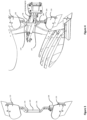
- Figures 1A to 1C show various views of an agricultural implement, particularly a plough 10.
- the plough 10 shown in Figures 1A to 1C is a reversible plough.
- the plough 10 comprises a main frame 12.
- the main frame 12 may be a rectangular tube extending between a headstock 14 at a front end 16 of the plough towards a plough wheel 20 at a rear end 18 of the plough.
- the main frame 12 supports a variety of ground-engaging tools.
- the ground engaging tools include plough bodies 22a, 22b, 24a, 24b, 26a, 26b, 28a, 28b, 30a, 30b and plough skimmers 32a, 32b, 34a, 34b, 36a, 36b, 38a, 38b, 40a, 40b.
- Each of the plough bodies 22a, 22b, 24a, 24b, 26a, 26b, 28a, 28b, 30a, 30b are connected to the main frame 12 by means of beams 42, 44, 46, 48, 50.
- Each of the beams 42, 44, 46, 48, 50 has a substantially Y-shaped structure, because it connects two plough bodies to the main frame 12, as discussed below.
- a first beam 42 supports a first pair of plough bodies 22a, 22b.
- a second beam 44 supports a second pair of plough bodies 24a, 24b.
- a third beam 46 supports a third pair of plough bodies 26a, 26b.
- a fourth beam 48 supports a fourth pair of plough bodies 28a, 28b.
- a fifth beam 50 supports a fifth pair of plough bodies 30a, 30b.
- Each of the pairs of plough bodies 22a, 22b, 24a, 24b, 26a, 26b, 28a, 28b, 30a, 30b is designed to create a furrow in the field when the plough is dragged behind or pushed by an agricultural vehicle such as a tractor. It follows that each run of the illustrated plough 10 through a field creates five adjacent furrows.
- FIG 8 a typical operation of agricultural machinery comprising a tractor 7 and a plough 10 is described.
- the plough 10 is drawn as an attachment (implement) behind an agricultural towing vehicle (e.g. tractor 7). It will be appreciated that it is equivalently feasible to locate the plough 10 in front of or both in front of and behind the tractor 7.
- Figure 8 shows a schematic work area 1, e.g. a crop field, which is divided into a main field 3 and headlands 5,6.
- a tractor 7 draws the plough 10 across the main field 3 in generally parallel working rows.
- the working rows are part of the trajectory of the tractor and typically run in parallel with a long edge of the work area 1.
- Each working row represents an individual run of the agricultural machinery across the field between headlands 5 and 6.
- a five-furrow plough such as the exemplary plough shown in Figures 1A to 1C creates a total of five furrows per run.
- the tractor 7 and plough 10 use the upcoming headland 5 or 6 for turning around, as indicated by trajectory 8.
- the soil of the headlands 5, 6 is subject to greater levels of soil compaction as it receives more traffic per unit area than the main field 3.
- the plough 10 is working on the main field 3 and, therefore, is arranged in the operating position. As the plough 10 reaches the border between the headland 5/6 and the main field 3, the plough 10 is transferred to a transfer position. It follows that each working row starts with an adjustment of the plough from the transfer position into the operating position and ends with an adjustment of the plough from the operating position into the transfer position.
- the plough 10 shown in Figures 1A to 1C is of the fully-mounted type.
- the weight of the plough is carried exclusively by the tractor when the plough is in its transfer position (on the headlands).
- the plough is then exclusively supported by the tractor 7 via headstock 14 and may be lifted off the ground with a lift cylinder of a tractor linkage.
- the plough 10 is also reversed. That is, the main frame 12 is rotated by about 180 degrees with respect to the headstock 14 to move the plough from a first configuration to a second configuration. It will be appreciated that if the operator is ploughing in the furrow (as shown in Figure 4 ), then the main frame 12 may not be rotated by exactly 180 degrees, it is more likely to be 190-200 degrees or 160-170 degrees depending on which direction the main frame 12 turns. If operator is ploughing on-land, then the main frame 12 may be rotated by an angle that is closer to 180 degrees, perhaps exactly 180 degrees.
- the plough 10 is set up such that plough bodies 22a, 24a, 26a, 28a, and 30a of each of the pairs are in contact with the soil.
- This first configuration is shown in Figure 8 and sometimes referred to as the "right turning configuration", since the mouldboards of the plough bodies 22a, 24a, 26a, 28a and 30a are arranged to move the soil sideways from left to right when viewed in the direction of travel.
- the plough 10 is set up such that plough bodies 22b, 24b, 26b, 28b, and 30b of each of the pairs are in contact with the soil.
- This second configuration is achieved after rotating the main frame by 180 degrees, such that the majority of plough bodies are arranged to the right of the tractor (not shown). It follows that the second configuration is also referred to as the "left turning configuration".
- Tilling the field with the plough 10 in this first configuration provides a first furrow created by the first plough body 22a, a second furrow created by the second plough body 24a, a third furrow created by the third plough body 26a, a fourth furrow created by the fourth plough body 28a, and a fifth furrow created by the fifth plough body 30a.
- a furrow width is determined by the lateral distance d between the plough bodies 22a, 22b, 24a, 24b, 26a, 26b, 28a, 28b, 30a, 30b, as illustrated in Figure 1C .
- the main frame 12 is rotated by 180 degrees (reversed) with respect to the headstock 14.
- a turning cylinder (not shown), attached to the headstock 14 is typically used to rotate (reverse) the plough 10.
- the first set of plough bodies e.g. 22a, 24a, 26a, 28a, 30a
- the second set of plough bodies e.g. 22b, 24b, 26b, 28b, 30b, that were not in use in the previous run is then transferred to the lower end of the plough 10 and will be submerged in the soil during the next run.
- the reversible plough is then in its second configuration (not shown).
- Executing a second run of the field with the plough 10 in this second configuration provides a first furrow created by the sixth plough body 22b, a second furrow created by the seventh plough body 24b, a third furrow created by the eighth plough body 26b, a fourth furrow created by the ninth plough body 28b, and a fifth furrow created by the tenth plough body 30b.
- Reversing the plough 10 between consecutive runs has the advantage that the plough bodies 22a, 22b, 24a, 24b, 26a, 26b, 28a, 28b, 30a, 30b that engage the soil always face the same side edge of the main field 3, irrespective of the tractor's orientation.
- skimmers 32a, 32b, 34a, 34b, 36a, 36b, 38a, 38b, 40a, 40b are attached in front of the plough bodies 22a, 22b, 24a, 24b, 26a, 26b, 28a, 28b, 30a, 30b.
- a first pair of skimmers 32a, 32b is arranged in front the first pair of plough bodies 22a, 22b.
- a second pair of skimmers 34a, 34b is arranged in front of the second pair of plough bodies 24a, 24b.
- a third pair of skimmers 36a, 36b is attached in front of the third pair of plough bodies 26a, 26b.
- a fourth pair of skimmers 38a, 38b is attached in front of the fourth pair of plough bodies 28a, 28b.
- a fifth pair of skimmers 40a, 40b is attached in front of the fifth pair of plough bodies 30a, 30b.
- skimmers 32a, 32b, 34a, 34b, 36a, 36b, 38a, 38b, 40a, 40b are arranged higher than their corresponding plough bodies 22a, 22b, 24a, 24b, 26a, 26b, 28a, 28b, 30a, 30b to not penetrate the soil as far as the plough bodies. It follows that the skimmers 32a, 32b, 34a, 34b, 36a, 36b, 38a, 38b, 40a, 40b are configured to only lift a top layer off the ground surface before the soil is turned over by the plough body that is arranged immediately behind the skimmer.
- Each pair of skimmers 32a, 32b, 34a, 34b, 36a, 36b, 38a, 38b, 40a, 40b is attached to the main frame 12 by means of a mounting assembly 52, 54, 56, 58, 60.
- the length of the mounting assemblies 52, 54, 56, 58, 60 determines the distance between the main frame 12 and the skimmers, and thus the working depth of the skimmers 32a, 32b, 34a, 34b, 36a, 36b, 38a, 38b, 40a, 40b.
- the length of the mounting assemblies 52, 54, 56, 58, 60 are non-adjustable.
- the plough bodies 22a, 22b, 24a, 24b, 26a, 26b, 28a, 28b, 30a, 30b, as traditional beams 42, 44, 46, 48, 50 are not adjustable. It follows that, in more traditional ploughs, the working depth relationship between the plough bodies and the skimmers is fixed, such that the working depth of the skimmers and plough bodies may only be adjusted together.
- Adjustment of the working depth of the skimmers 32a, 32b, 34a, 34b, 36a, 36b, 38a, 38b, 40a, 40b and the plough bodies 22a, 22b, 24a, 24b, 26a, 26b, 28a, 28b, 30a, 30b may be achieved by means of a linkage 62 that attaches the plough wheel 20 to the frame 12.
- the main frame 12 moves closer to the ground surface, thereby increasing the working depth of the plough bodies 22a, 22b, 24a, 24b, 26a, 26b, 28a, 28b, 30a, 30b and the skimmers 32a, 32b, 34a, 34b, 36a, 36b, 38a, 38b, 40a, 40b.
- linkage 62 is extended, such as the main frame 12 is distanced further from the ground surface, thereby pulling the plough bodies 22a, 22b, 24a, 24b, 26a, 26b, 28a, 28b, 30a, 30b and the skimmers 32a, 32b, 34a, 34b, 36a, 36b, 38a, 38b, 40a, 40b out of the ground.
- the mounting assembly of the invention allows for a working depth adjustment of the plough skimmers independently of the plough bodies.
- the mounting assembly renders the distance between the plough skimmers 32a, 32b, 34a, 34b, 36a, 36b, 38a, 38b, 40a, 40b and the main frame 12 adjustable.
- FIGs 2A and 2B show an embodiment of a mounting assembly according to the invention.
- the mounting assembly 100 is used to connect the skimmer 130 to the main frame 12 of the plough 10. It should be noted that the mounting assembly 100 may either be mounted on a conventional, non-reversible plough or on a reversible plough, such as the plough 10 shown in Figures 1Ato 1C .
- the skimmer 130 shown in Figures 2A and 2B generally comprises three parts that are removably attached to each other: a mouldboard 132, a saddle or frog 134, and a share 136.
- the mouldboard 132 of the skimmer 130 is connected to the saddle or frog 134.
- the mouldboard 132 is removably connected to the frog 134 by means of various fastening members 138.
- Adjacent to the mouldboard 132 there is provided the share 136.
- the share 136 is arranged below the mouldboard 132 in the configuration shown in Figures 2A and 2B .
- the share 136 is removably connected to the frog 134 by means of fastening member 139.
- the share 136 is designed to engage the soil and lift off a top layer of the soil while the mouldboard 132 will overturn the so lifted soil in preparation for the plough bodies.
- the skimmer 130 is connected to the mounting assembly 100 via a back end of the frog 134.
- the mounting assembly 100 shown in Figures 2A and 2B comprises a mounting rail 102, which is connected to the main frame 12, as will be described in more detail below.
- the mounting rail 102 may be a solid rail with a polygonal cross-section.
- the mounting rail has a first side 116 and an opposite second side 118.
- third and fourth sides 120, 122 extend transversely to and connect the first and second sides 116, 118.
- the mounting assembly 100 further comprises a skimmer support bracket 104.
- the skimmer support bracket 104 surrounds a part of the length of mounting rail 102, as is illustrated in Figures 2A and 2B .
- the skimmer support bracket 104 has a collar-like shape that matches the shape of the mounting rail 102.
- an inner surface of the skimmer support bracket 104 matches the outer surface of the mounting rail 102.
- the skimmer support bracket 104 is connected to the mounting rail 102 via a removable locking pin 106.
- the locking pin 106 may extend through the skimmer support bracket 104 and the mounting rail 102.
- the mounting rail 102 comprises a plurality of mounting holes 108 distributed along its length. In the example of Figures 2A and 2B , the mounting holes 108 of the mounting rail 102 are distributed equidistantly along the length of the mounting rail 102. The mounting holes 108 of the mounting rail 102 are sized to receive the locking pin 106.
- the mounting bracket 104 comprises mounting holes 110 sized to receive the locking pin 106.
- the mounting holes 110 of the skimmer support bracket 104 are arranged either side of the mounting rail 102, when the support bracket 104 is slipped over the mounting rail 102.
- the skimmer support bracket 104 comprises two mounting holes 110 on both sides of the mounting rail 102.
- the longitudinally spaced mounting holes 110 on each side of the skimmer support bracket 104 are offset from each other by a distance that is slightly larger than a distance between the mounting holes 108 of the mounting rail 102.
- the position of the skimmer support bracket 104 with respect to the mounting rail 102 can be changed either by aligning the support bracket 104 with different mounting holes 108 of the mounting rail 102 and/or by changing the pin from one pair of mounting holes 110 to the other pair of mounting holes 110.
- the mounting rail 102 is preferably rigidly attached to the main frame 12. Accordingly, any movement of the skimmer support bracket 104 with respect to the mounting rail 102 results in an adjustment of the skimmer support bracket with respect to the main frame 12. This adjustment of the position of the skimmer support bracket 104 with respect to the main frame 12 results in a depth adjustment of the skimmer 130 attached to the skimmer support bracket 104.
- the skimmer 130 is attached to the skimmer support bracket 104 at a back end of the frog 134.
- the frog 134 is connected to the skimmer support bracket via one or more fastening members 124.
- the skimmer support bracket 104 shown in Figures 2A and 2B is manufactured as a two-piece structure.
- the skimmer support bracket 104 comprises a first part 112 and a second part 114.
- the first and second parts 112, 114 are manufactured individually and permanently connected to each other thereafter.
- the first and second parts 112, 114 of the skimmer support bracket 104 are permanently attached to each other by means of welding (welds 160, 162 are shown in Figure 5B ).
- the first part 112 of the skimmer support bracket 104 is shaped to cover a first side 116 of the mounting rail 102. As set out in more detail below, the first part 112 of the skimmer support bracket 104 is shaped to contact first and second bevelled edges 126, 128 of the mounting rail.
- the second part 114 of the skimmer support bracket 104 is shaped to be attached to a second side 118 of the mounting rail 102, the second side 118 being opposite to the first side 116.
- the first part 112 of the skimmer support bracket 104 has a U-shaped cross-section and thus not only covers the first side 116 of the mounting rail 102 but also the third and fourth sides 120, 122 of the mounting rail 102.
- the legs of the U-shaped first part 112 are spaced slightly from the third and fourth sides 120, 122 to avoid contact between the legs and the third and fourth sides 120, 122, when the skimmer support bracket 104 is connected to the mounting rail.
- the second part 114 of the skimmer support bracket 104 is plate-shaped.
- the second part 114 is an L-shaped plate.
- the second part 114 is connected to the first part 112 at a first end (e.g. by welding).
- the second part 114 is releasably connected to the frog 134 by means of removable fastening members 124.
- One or both fastening members 124 may also act as a stone protection and may thus be shear bolts.
- the first and second parts 112, 114 are designed to surround at least parts of the mounting rail 102. In the illustrated embodiment, the first and second parts together create a collar that encompasses the mounting rail 102.
- the mounting rail 102 is a chamfered polygon.
- a first bevelled edge 126 extends between the first side 116 and the third side 120 of the mounting rail 102.
- a second bevelled edge 128 extends between the first side 116 and the fourth side 122 of the mounting rail 102.
- the bevelled edges act as mating surfaces between the mounting rail 102 and the skimmer support bracket 104.
- the bevelled edges 126, 128 are mating surfaces between the mounting rail 102 and the first part 112 of the skimmer support bracket 104.
- Both bevelled edges 126 and 128 of the mounting rail 102 are arranged obliquely to a ploughing direction (150, Figure 5B ).
- the mounting bracket 104 includes mating surfaces, which are aligned and mate with the bevelled edges 126, 128 of the mounting rail 102.
- a first mating surface 140 of the skimmer support bracket 104 is arranged to mate with the first bevelled edge 126 of the mounting rail 102.
- a second mating surface 142 of the skimmer mounting bracket 104 is arranged to mate with the second bevelled edge 128 of the mounting rail 102.
- the mating surfaces 140, 142 of the skimmer support bracket 104 extend at the same angle with respect to the ploughing direction as the first and second bevelled edges 126, 128 of the mounting rail 102.
- the first mating surface 140 extends between a base and a first leg of the U-shaped first part 112.
- the second mating surface 142 extends between the base and a second leg of the U-shaped first part 112.
- the skimmer support bracket 104 and the mounting rail 102 are formed to only contact each other in three regions, when in use.
- a first contact area is set to be between the second part 114 of the skimmer support bracket 104 and the second side 118 of the mounting rail.
- a second contact area is formed between the first bevelled edge 126 of the mounting rail 102 and a first mating surface 140 of the skimmer support bracket.
- a third contact area is formed between the second bevelled edge 128 of the mounting rail 102 and a second mating surface 142 of the skimmer support bracket 104.
- FIGs 3 and 4 show an application of the mounting assembly 100 shown in Figures 2A and 2B for a reversible plough.
- the mounting rail 102 carries two skimmer support brackets 104 (only the lower support bracket is visible), one for a first (lower) skimmer 170 and one for a second (upper) skimmer 172.
- the mounting rail 102 may be removably connected to the main frame 12 via mounting holes 174, 176. Mounting holes 174, 176 can be aligned with and connected to attachment lugs 178, 180 on the main frame 12.
- the two skimmer support brackets 104 of the mounting rail 102 can be adjusted independently.
- the lower skimmer support bracket 104 can be used to adjust the depth of the lower skimmer 170 independently of the depth of the upper skimmer 172 that is set by the upper skimmer support bracket (not shown).
- the mounting rail 102 may further feature a curved design that is adapted to receive a part of the beam frame such that the beam frame and the upper and lower skimmers 170, 172 are in vertical alignment when the mounting rail is attached to the beam.
- FIG. 5A An example of such a reactive force 152 is shown in Figure 5A .
- the reactive force 152 acts on the skimmers (not shown in Figure 5A ), which transfer the force onto the skimmer support bracket 104, via the second part 114.
- the reactive force 152 creates a torque M about pin 106, the torque M acting to press the skimmer support bracket 104 against the outside surface of the mounting rail 102.
- the skimmer support bracket 104 will be biased against the mounting rail 102 in planes P1 and P2.
- Figures 5B and 5C there are shown schematic cross-sections of the mounting assembly 100 shown in Figures 2A and 2B , along planes P1 and P2 of Figure 5A .
- Figure 5B shows a cross-section along plane P1 of Figure 5A .
- the reactive force 152 is applied to the skimmers and, therefore, the mounting assembly 100.
- the reactive force 152 acts in a direction opposite to the ploughing direction 150 of the plough 10.
- Reactive force 152 will act on the skimmer 130/170 and be transferred to the support bracket 104 via frog 134 such that the support bracket is pushed into engagement with the mounting rail 102, as is schematically illustrated in Figure 5B .
- plane P1 the first part 112 of the skimmer support bracket 104 will be biased against the mounting rail 102.
- the mating surface 140 is being pushed towards the bevelled edge 126 of the mounting rail 102 by reactive force 152.
- both the first mating surface 140 and the corresponding first bevelled edge 126 are arranged obliquely to the ploughing direction 150, and thus also obliquely with respect to the reactive force 152.
- the reactive force 152 tries to slide the skimmer support bracket 104 in the direction of the first force component 154 along the bevelled edge 126. This will cause the second mating surface 142 of the skimmer support bracket 104 to be pushed away from the second bevelled edge 128. At the same time, the skimmer support bracket 104 will be pushed against the second side 118 of the mounting rail 102.
- the mating surfaces 126, 140 together cause a movement of the skimmer support bracket 104 with respect to the mounting rail 102, that wedges the first bevelled edge 126 and the second side 118 of the mounting rail 102 between the first and the second parts 112, 114 of the skimmer support bracket 104.
- the creation of the two force components 154, 156 results in a self-locking effect in two different directions that are perpendicular in this example. It follows that the skimmer support bracket 104 is prevented from movement with respect to the mounting rail 102 in a horizontal plane that coincides with the cross-sectional plane of Figures 5B and 5C . At the same time, movement of the skimmer support bracket 104 with respect to the mounting rail 102 in a vertical direction is prevented by means of the locking pin 106 described above. Accordingly, the mounting assembly of the invention is locked in three translational degrees of freedom when the plough skimmers are in use.
- an opposite end of the skimmer support bracket 104 contacts the mounting rail 102, due to torque M. More specifically, the second mating surface 142 of the skimmer support bracket 104 is pushed against the second bevelled edge 128 of the mounting rail 102 by torque M. The torque M results in force components acting perpendicular directions. A first force component acts in parallel with the second mating surface 142/the second bevelled edge 128. A second force component acts perpendicular to the second mating surface 142 of the skimmer support bracket 104/the second bevelled edge 128 of the mounting rail 102.
- the moment M tries to slide the skimmer support bracket 104 in the direction of the first force component along the bevelled edge 128. This will cause the first mating surface 140 of the skimmer support bracket 104 to be pushed away from the first bevelled edge 126. At the same time, the skimmer support bracket 104 will be pushed against the second side 118 of the mounting rail 102.
- the mating surfaces 128, 142 together cause a movement of the skimmer support bracket 104 with respect to the mounting rail 102, that wedges the second bevelled edge 128 and the second side 118 of the mounting rail 102 between the first and the second parts 112, 114 of the skimmer support bracket 104.
- an outer surface of the mounting rail 102 substantially matches an inner surface of the skimmer support bracket 104.
- the shapes of the mounting rail 102 and the skimmer support bracket 104 are designed such that the skimmer support bracket 104 can only contact the mounting rail along surfaces 118, 126, and 128.
- the remaining surfaces 116, 120, and 122 will remain spaced from the skimmer support bracket 104 to guarantee that reactive force 152 is transferred to the mounting rail 102 via mating surfaces 126, 140 or 128, 142 respectively.
- a first gap 182 is provided between the first part 112 of the skimmer support bracket 104 and the third surface 120 of the mounting rail 102.
- a second gap 184 is provided between the first part 112 of the skimmer support bracket 104 and the fourth surface 122 of the mounting rail 102.
- a third gap 186 is provided between the first part 112 of the skimmer support bracket 104 and the first surface 116 of the mounting rail 102. Consequently, the first part 112 of the skimmer support bracket 104 contacts only the bevelled edges 126 and 128 of the mounting rail 102 with the corresponding mating surfaces 140, 142.
- FIG. 6A and 6B An alternative arrangement of the mounting assembly according to the present invention is shown in Figures 6A and 6B .
- the mounting assembly 200 of this embodiment is schematically represented by cross-sections similar to the one illustrated in Figure 5B .
- Figures 6A and 6B show cross sections along a plane that corresponds to P1 of Figure 5A .
- the assembly is at rest, i.e. the reactive force 152 is not yet acting on the skimmer support bracket 104.
- Figure 6B shows a state in which the skimmer support bracket 204 is biased towards the mounting rail 202 by means of a reactive force 252.
- the mounting assembly of the embodiment in Figures 6A and 6B has a mounting rail 202 that does not include bevelled edges. Rather, the mounting rail 202 of mounting assembly 200 is substantially rectangular in cross-section.
- the corresponding skimmer support bracket 204 also has a substantially rectangular shape that matches the rectangular shape of the mounting rail 202.
- the skimmer support bracket 204 is constructed as a two-piece structure with a first part 206 and a second part 208.
- the first part 206 is arranged to be connected to a first surface 209 and a third surface 212 of the mounting rail 202.
- the second part 208 is arranged to connect to a second surface 210 and a fourth surface 214 of the mounting rail 202.
- the second surface 210 is opposite to the first surface 209.
- the fourth surface 214 is opposite the third surface 212.
- the first and second parts 206, 208 of the skimmer support brackets 204 are substantially identical in their cross-section. Both the first and second parts 206, 208 have a substantially L-shaped cross section.
- Each of the two parts 206, 208 makes up about half of the support bracket 204.
- the first and second parts 206, 208 in this example are welded together by welds 260, 262 along joining edges.
- the first part 206 of the skimmer support bracket 204 includes a first mating surface 216 and a second mating surface 218.
- the first mating surface 216 of the first part 206 is arranged to mate with the first surface 208 of the mounting rail 202, when the plough is in use.
- the second mating surface 218 of the first part 206 is arranged to mate with the third surface 212 of the mounting rail 202, when the plough is in use.
- Both the first and second mating surfaces 216, 218 of the skimmer support bracket 204 are arranged obliquely with respect to a ploughing direction 250.
- the first surface 208 and the third surface 212 of the mounting rail 202 are arranged with respect to the ploughing direction 250 at substantially the same, oblique angle as the first and second mating surfaces 216, 218.
- a reactive force 252 acting on the skimmer support bracket 204 will brace the first and second mating surfaces 216, 218 against the corresponding surfaces 209, 212 of the mounting rail 202. Due to the oblique angle between the mating surfaces and the ploughing direction 250, first and second force components 254, 256 will act to brace the skimmer support bracket 204 and the mounting rail 202 against each other in two directions. The two directions are perpendicular to each other and provide a self-locking effect in a horizontal plane that coincides with the cross-sectional plane of Figures 6A and 6B .
- FIG. 7 there is shown a schematic cross-section of another embodiment of the mounting assembly.
- the mounting assembly 400 of the embodiment in Figure 7 corresponds mainly to the arrangement of the embodiment shown in Figure 6 .
- the skimmer support bracket 404 of this embodiment is a four-piece part.
- a first part 406 may be arranged next to a first surface 409 of the mounting rail 402.
- a second part 408 may be arranged opposite to the first part 406 and next to a second surface 410 of the mounting rail 402.
- a third part 416 may be arranged next to a third surface 412 of the mounting rail 402.
- a fourth part 418 may be arranged opposite to the third part 416 and next to a fourth surface 414 of the mounting rail 402.
- the first, second, third, and fourth parts 406, 408, 416, 418 in this example are welded together by welds 460, 462, 464, and 464 along joining edges to form a substantially rectangular skimmer support bracket 404.
- a reactive force 252 acting on the skimmer support bracket 404 will brace the first and second mating surfaces (inside surfaces of parts 406 and 416) against the corresponding surfaces 409, 412 of the mounting rail 402. Due to the oblique angle between the mating surfaces and the ploughing direction 250, first and second force components will act to brace the skimmer support bracket 404 and the mounting rail 402 against each other in two directions.
- the mounting assembly of the invention may have any shape or arrangement, as long as their mating surfaces act to distribute the reactive force of the plough skimmers in two directions, which are oblique to the ploughing direction.
- the mounting rail and the skimmer support bracket are arranged with respect to each other such that the reactive force 152, 252 acting on the skimmers is split into two force components, both of which act in different directions and are oblique to the ploughing direction.
- Figure 9 shows a flow diagram relating to a method for manufacture of a mounting assembly.
- the method 300 includes a first step 302 for providing a mounting rail and the two separate parts of a skimmer support bracket such as support bracket 104 described above. In other words, in step 302 the two parts of the skimmer support bracket are not yet connected to each other.
- the first part of the skimmer support bracket is arranged on a first side of the mounting rail.
- the first part 112 of the mounting bracket 104 may be slipped over the mounting rail 102 such that the first and second mating surfaces 140, 142 engage with the first and second bevelled edges 126, 128.
- the first part 112 may then be temporarily connected to the mounting rail 102, e.g. by means of mechanical clamps such that the first part 112 remains in contact with the mounting rail 102 until the first and second parts are connected.
- the method comprises arranging the second part of the skimmer on an opposite, second side of the mounting rail.
- the second part 114 of the skimmer support bracket 104 is plate-shaped and sized so as to fit between the limbs of the U-shaped first part 112. Accordingly, in step 306 the second part 114 may be slipped between the limbs of the first part 112 and brought into contact with the second surface 118 of the mounting rail 102. Similarly to the first part 112, the second part 114 may be temporarily fixed into position by means of a mechanical clamp. Additionally or alternatively, the temporary connection between the first and second parts 112, 114 of the skimmer support bracket 104 and the mounting rail 102 may be provided by means of a locking pin, such as locking pin 106.
- first part and the second part of the skimmer support bracket are connected to each other.
- first part 112 and the second part 114 may be connected by means of welding.
- a schematic welding connection is shown in Figures 5B and 5C .
- a first weld 160 is provided along a first contact edge between the first and second parts 112, 114 and a second weld line 162 is provided on the opposite edge between the first and second parts 112, 114.
- the first and second parts 112, 114 could also be connected to each other in any other way such as gluing or even by means of a removable connection.
- step 308 the temporary connections between the first and second part and the mounting rail can be removed.
- the resulting skimmer mounting bracket 104 is then moveable along the length of the mounting rail 102 and may be fixed to the latter at different positions determined by mounting holes 108 or 110 respectively.
- the use of this manufacturing method has the advantage that play between the skimmer support bracket 104 and the mounting rail 102 can be adjusted accurately and repeatably.
- the first and second parts 112, 114 may either be attached directly to the outer surface of the mounting rail 102 or spaced from the latter via spacer elements.
- the spacer elements can define exact gaps that aid movement of the skimmer support bracket 104 along the length of the mounting rail 102, yet prevent excessive amounts of vibration between the skimmer support bracket 104 and the mounting rail 102.
- first and second parts of the skimmer support bracket may have any shape that act together to surround parts of the mounting rail.
- both parts may be constructed as U-shaped pieces, which are then joined at their respective limbs.
- the skimmer support bracket from more than two pieces, for as long as each of the pieces is designed to match the contours of one side surface of the mounting rail.
Description
- The present disclosure relates to a mounting assembly for agricultural vehicles, particularly a mounting assembly for ground engaging parts of agricultural implements. In one aspect of the invention, there is provided a mounting assembly for a plough skimmer. Another aspect relates to a method for manufacturing such mounting assemblies.
- In agriculture, farming cycles are followed that can roughly be divided into the different steps of land preparation, seed sowing, fertilizing, irrigation, crop growth, and harvesting. Each of these steps is critical to yield optimal crop results and achieve the desired returns on initial investments. Of the listed steps, land preparation is typically further divided into steps of, as necessary, clearing obstructions (e.g. bushes, stones and rocks) and subsequent tillage.
- Tilling crumbles and loosens the soil, improves the soil structure and incorporates crop residues and manure into the soil, thus fertilizing the ground. The improved soil structure allows for increased plant root growth, soil aeration and water penetration/filtration. Overall this results in higher yields, better long-term soil fertility, soil moisture retention, and weed management. Tillage can be separated into primary (relatively deep) and secondary (relatively shallow) tillage. In primary tillage, such as ploughing, the soil is turned over such that nutrients come to the surface. In addition to turning up the soil to bring fresh nutrients to the top and depositing plant residue below where it will break down, this process also aerates the earth - enabling it to hold more moisture. Preparing the land to a greater depth produces a rougher surface finish than secondary tillage. Secondary tillage (e.g. seedbed cultivation) breaks up soil clods into smaller masses which might be desirable for small seeds or plants that have minimal clod-handling ability.
- Primary tillage, and particularly ploughing, is widely regarded as one of the most effective ways of preventing crop disease, removing weeds, and controlling mice and other pests. In its simplest form the turnplough, also known as the mouldboard plough, includes a variety of plough bodies, which are blades for penetrating and turning over the soil in arrays of adjacent trenches, known as furrows. Modern ploughs typically include a plurality of plough bodies connected to a plough frame such that they are laterally offset manner from each other when the plough is in use. Each plough body is connected to the plough frame via corresponding beams. The plough frame, in turn, is connected to a towing or pushing vehicle via a hitch arranged at a front or back end of the frame.
- In addition to the plough bodies, it is known to use so-called "plough skimmers". Typically, one skimmer is placed in front of every plough body. The purpose of the plough skimmers is primarily to cut a shallow layer off the top of the ground surface before the latter is turned over by the plough bodies. The use of plough skimmers results in a more even ploughing result and reduces the amount of plant residues left on the ground surface after ploughing. Accordingly, the use of skimmers further reduces the possibility of inadvertent plant growth in ploughed fields.
- Depending on the contours of the work area and the status of the soil, there is a need for the skimmer depth to be adjustable to ensure that the skimmers can be placed in the correct working depth. For example, skimmers are typically arranged up to 10cm below the ground surface. Arranging the skimmers in a position that is significantly higher or lower than this may reduce the quality of the ploughing result.
- The depth adjustment can be achieved in two different ways. In a first skimmer mount type, a mounting bracket holds a shaft (or rail) that is connected to the skimmer. The skimmer shaft runs within the mounting bracket and may be fixed with respect to the bracket by tightening one or more threaded bolts against an outer surface of the shaft. To adjust the depth of the skimmer, the threaded bolts are loosened, and the shaft can be moved up and down with respect to the bracket. Once the depth is adjusted, the bolt is again tightened to fix the skimmer shaft in place. Adjusting the depth with this arrangement usually requires one or more tools to loosen and/or tighten the bolts. A tool-free solution is a skimmer mount type that utilises a pin interlocking the mounting bracket with the shaft to set the depth. To adjust the depth, the pin is removed, thereby allowing movement between the skimmer shaft and the mounting bracket. Once the desired depth is reached, the pin is reinserted in a new position along the shaft. Although this second solution requires no tools for depth adjustment, the connection between the mounting bracket and the skimmer shaft can exhibit significant play, leading to vibrating movements and thus wear between the mounting bracket and the skimmer shaft.
- In view of the aforementioned problem, there is a need to provide an improved mounting assembly that is easily adjustable without tools and, at the same time, exhibits reduced vibration and wear.
-
DE 7415663 U discloses a skimmer support bracket in which a collar-like first part surrounds a support member in the form of a rod having a flattened portion against which a section of the interior of the first part bears in use. A bolt extends through a threaded hole in the first part to engage the rod and secure the skimmer to the rod. - It is an aim of the present invention to solve or at least ameliorate one or more of problems discussed above.
- Aspects and embodiments of the disclosure provide a mounting assembly and a method for manufacturing a mounting assembly as claimed in the appended claims.
- According to an aspect of the invention, there is provided a mounting assembly for a plough skimmer, the mounting assembly comprising a mounting rail configured to be connected to the main frame of a plough and a skimmer support bracket adapted to connect a plough skimmer to the mounting rail. The skimmer support bracket is adapted to surround parts of the mounting rail, the mounting rail and the skimmer support bracket having aligned mating surfaces that are arranged obliquely to a ploughing direction such that the mounting rail and the skimmer support bracket are braced against each other in at least two directions when the plough skimmer is in use and
wherein the skimmer support bracket is a two-piece structure comprising a first part for connection with a first side of the mounting rail and a second part for connection with an opposite, second side of the mounting rail, the mounting assembly being characterised in that the first and second parts of the skimmer support bracket are permanently connected to each other. - During use of the plough, reactive forces created by dragging the skimmers through the soil are transferred to the mating surfaces at an oblique angle, thereby separating said force into two components. A first force vector acts to brace the mounting rail and the skimmer support bracket against each other in a direction that is perpendicular to the mating surfaces. A second force vector acts to brace the mounting rail and the skimmer support bracket against each other in a direction that is parallel with the mating surfaces. Arranging the mounting rail and the skimmer support bracket such that they are braced against each other in more than one direction will result in a self-locking connection between the mounting rail and the skimmer support bracket. It should be understood that the arrangement of the mating surfaces will define the directions of self-locking forces acting on the mounting assembly of the present disclosure. The mounting rail and the skimmer support bracket may be shaped or connected to each other in a way that allows the forces transferred from the ground into the mounting rail to be split in two directions that may be oblique to the ploughing direction. This self-locking connection in two directions significantly reduces play and thus wear between the mounting rail and the skimmer support bracket.
- The at least two directions may be perpendicular to each other. In other words, the mounting assembly will be locked in place in a two-dimensional plane defined by the at least two directions. Traditional skimmer arrangements, in which the mounting rail and the skimmer support brackets are braced against each other in the ploughing direction only, tend to be susceptible to vibrations in a direction lateral to the ploughing direction. The mounting assembly of the invention avoids such vibrations by converting the force applied to the skimmer into separate force components applied to the skimmer support bracket and the mounting rail in perpendicular directions.
- In one embodiment, the mating surfaces are arranged at an angle of 10 degrees to 80 degrees, preferably at an angle of 30 degrees to 60 degrees, with respect to the ploughing direction. Ranging the mating surfaces at an angle of, for example, 45 degrees will distribute the ploughing forces evenly between the two directions mentioned above. This will act to self-lock the mounting assembly in both directions equivalently. However, in order to avoid excessive forces in one of the two directions and/or to increase the force in one of the two directions, the angle of the mating surfaces may be changed. A larger share of the reactive force may be applied in one of the two directions, resulting in lower forces bracing the mounting bracket and the mounting rail together in the respective other direction.
- In yet another embodiment, a first mating surface of the mounting rail is a bevelled edge. The mounting rail may have a substantially polygonal cross-section. If none of the side surfaces of the mounting rail are arranged oblique to the to the ploughing direction, then a bevelled edge connecting two side surfaces will be oblique and act to split the ploughing forces into two perpendicular directions to achieve the above self-locking effect.
- According to another embodiment, an outer surface contour of the mounting rail matches an inner surface contour of the skimmer support bracket. In other words, each of the sides on the outer surface of the mounting rail has a corresponding side on the inner surface of the mounting bracket. At least one pair of matching sides may be arranged obliquely to the ploughing direction such that the pair of matching sides represent oblique mating surfaces.
- In another embodiment, the mounting rail and the skimmer support bracket are arranged such that the mounting bracket may be fixed to the mounting rail at a plurality of locations along the length of the mounting rail. In other words, the depth of the skimmer with respect to the plough frame may easily be adjusted by moving the skimmer support bracket up and down along the length of the mounting rail.
- The skimmer support bracket may be connected to the mounting rail by means of a mounting pin, the mounting rail comprising a plurality of mounting holes distributed along the length of the mounting rail and adapted to receive the mounting pin. The mounting pin may extend through both a mounting hole within the skimmer support bracket and one of the plurality of mounting holes along the mounting rail. Whilst the self-locking effect is designed to lock the mounting assembly in a horizontal plane, the mounting pin acts to interlock the mounting rail and the skimmer support bracket in a vertical direction. The self-locking effect together with the interlocking effect of the mounting pin, therefore, avoid movement of the skimmer support bracket with respect to the mounting rail in three translational degrees of freedom, during the ploughing operation. When the ploughing operation is stopped, the self-locking effect ceases, and the skimmer support bracket may be moved with respect to the mounting rail, simply, by removing the mounting pin.
- As indicated the skimmer support bracket is a two-piece structure. In this specification, the term "two-piece structure" refers to two parts that are manufactured separately but may be connected to each other permanently or removably at a later stage. In other words, the skimmer support bracket is made up of at least two separate parts that will be connected to each other before use. As will be described in detail below, the two-piece structure of the skimmer support bracket may be used to significantly reduce play between the support bracket and the corresponding mounting rail.
- In accordance with the invention as broadly defined the mounting rail may be sandwiched between the first and second parts of the support bracket. The first and second parts may be arranged on opposite sides of the mounting rail and temporarily fixed to the latter using mechanical clamps (or similar means) before being connected to each other. In this way, the play between the skimmer support bracket and the mounting rail can be adjusted accurately. If both parts abut on their respective side with no gaps between them and the mounting rail, then there will be substantially no play and the skimmer support bracket may no longer be adjustable. Consequently, spacers may be used to create small gaps between the two parts and their respective sides of the mounting rail before joining the two parts of the skimmer support bracket. The gaps should be sized to reduce play whilst allowing for a smooth sliding movement of the skimmer support bracket on the mounting rail.
- In one embodiment, the first and second parts may be welded together. However, it will be understood that any other means of permanently connecting the first and second parts (e.g. gluing) may also be feasible.
- In yet another embodiment, the first part has a generally U-shaped cross section. As such, the first part may not to only cover the first but all sides of the mounting rail except the second side which, in turn, is covered by the second part of the support bracket. In other words, if the mounting rail has a rectangular cross-section, the U-shaped first part of the skimmer support bracket may cover three sides of the mounting rail, whereas the second part covers one side only, namely the second side of the mounting rail. The U-shaped first part may be formed in such a way that it can be slipped over the sides of the mounting rail.
- The second part may be plate shaped, preferably an L-shaped plate. The plate shaped second part may be sized to fit between the limbs of the U-shaped first part. The plate shaped second part and the U-shaped first part may be connected to each other to create a collar closely surrounding the mounting rail.
- In another embodiment, the first part of the skimmer support bracket comprises a first mating surface arranged on an inner surface of the skimmer support bracket, the first mating surface being shaped to mate with a first mating surface of the mounting rail, when the skimmer support bracket is connected to the mounting rail.
- In another aspect of the invention, there is provided a method for manufacturing a mounting assembly for a plough skimmer, the method comprising the following steps:
- providing a mounting rail adapted to be connected to the main frame of a plough;
- providing a skimmer support bracket for connecting a plough skimmer to the mounting rail, wherein the mounting rail and the skimmer support bracket have aligned mating surfaces that are arranged obliquely to a ploughing direction such that the mounting rail and the skimmer support bracket are braced against each other in at least two directions when the plough skimmer is in use and the skimmer support bracket being a two-piece structure comprising a first part and a second part wherein the first part is for connection with a first side of the mounting rail and the second part is for connection with an opposite, second side of the mounting rail;
- arranging the first part of the skimmer support bracket on a first side of the mounting rail; and
- arranging the second part of the skimmer on an opposite, second side of the mounting rail;
- characterised in that the method includes permanently connecting the first part and the second part of the skimmer support bracket with each other such that the skimmer support bracket surrounds parts of the mounting rail.
- The first part and the second part may be welded together.
- The first and second part may be temporarily connected to the sides of the mounting rail before the first and second parts are connected to each other. In one example, mechanical clamps may be used temporarily to connect the first and second part to the mounting rail.
- Spacers may be introduced between the first part and the first side of the mounting rail, before the first part and the second part are connected. Alternatively or additionally, spacers may be introduced between the second part and the second side of the mounting rail, before the first part and the second part are connected.
- According to another aspect of the invention, there is provided an agricultural implement comprising a main frame and at least one skimmer connected to the main frame by means of any of the above mounting assemblies. In one embodiment, the agricultural implement may be a plough, for example a reversible plough.
- In other embodiments of the disclosure, agricultural machinery is provided comprising the above agricultural implement connected to the front and/or rear of an agricultural vehicle, e.g. a tractor.
- The agricultural vehicle may include one or more control devices, such as but not limited to programmable or non-programmable processors. Similarly, the agricultural implement may include one or more control devices, such as but not limited to programmable or non-programmable processors. Additionally or alternatively, the agricultural implement may be controlled by one or more control devices of the agricultural vehicle. Similarly, the agricultural vehicle may be controlled by one or more control devices of the agricultural implement.
- The agricultural vehicle and/or the agricultural implement may be remotely controllable, e.g. from a farm office. Accordingly, the agricultural vehicle may include one or more communication interfaces for connection to a remote processor and/or a remote controller. Similarly, the agricultural implement may include one or more communication interfaces for connection to a remote processor and/or a remote controller.
- As disclosed but not specifically claimed herein a mounting assembly for a plough skimmer comprises a support bracket configured to be connected to the main frame of a plough and a skimmer mounting rail adapted to connect a plough skimmer to the support bracket rail. The support bracket is adapted to surround parts of the mounting rail, the mounting rail and the skimmer support bracket having aligned mating surfaces that are arranged obliquely to a ploughing direction such that the mounting rail and the skimmer support bracket are braced against each other in at least two directions when the plough skimmer is in use. The support bracket may be an integral part of the main frame. Further aspects of the support bracket and mounting rail, such as the bevelled edges, may be as described above.
- Within the scope of this application it is expressly intended that the various aspects, embodiments, examples and alternatives set out in the preceding paragraphs, and the claims and/or the following description and drawings, and in particular the individual features thereof, may be taken independently or in any workable combination. That is, all embodiments and all features of any embodiment can be combined in any way and/or combination, unless such features are incompatible.
- One or more embodiments of the invention will now be described by way of example only, with reference to the accompanying drawings, in which:
-
Figure 1A shows a left-side view of an exemplary plough implement; -
Figure 1B shows a right-side view of the plough implement ofFigure 1A ; -
Figure 1C shows a top view of the plough implement ofFigure 1A ; -
Figures 2A and 2B show perspective views of a mounting assembly according to an embodiment of the invention; -
Figure 3 shows a perspective view of a mounting assembly according to an embodiment of the invention with reversible skimmers; -
Figure 4 shows a perspective view of the embodiment shown inFigure 3 attached to the main frame of a plough implement; -
Figure 5A shows a schematic front view of the mounting assembly ofFigure 2A ; -
Figure 5B shows a schematic cross-section of the mounting assembly ofFigure 2A along plane P1; -
Figure 5C shows a schematic cross-section of the mounting assembly ofFigure 2A along plane P2; -
Figure 6A shows a schematic cross-section of another embodiment of the mounting assembly according to the invention in a static state; -
Figure 6B shows a schematic cross-section of the embodiment shown inFigure 6A during ploughing; -
Figure 7 shows a schematic cross-section of another embodiment of the mounting assembly according to the invention in a static state; -
Figure 8 shows a schematic trajectory of an agricultural machinery when working a field; -
Figure 9 shows a flow diagram of an embodiment of the method for manufacturing a mounting assembly of the invention. -
Figures 1A to 1C show various views of an agricultural implement, particularly aplough 10. As will be described in more detail below, theplough 10 shown inFigures 1A to 1C is a reversible plough. - The
plough 10 comprises amain frame 12. Themain frame 12 may be a rectangular tube extending between aheadstock 14 at afront end 16 of the plough towards aplough wheel 20 at arear end 18 of the plough. Themain frame 12 supports a variety of ground-engaging tools. In the example ofFigures 1A to 1C , the ground engaging tools includeplough bodies plough skimmers plough bodies main frame 12 by means ofbeams beams main frame 12, as discussed below. - A
first beam 42 supports a first pair ofplough bodies second beam 44 supports a second pair ofplough bodies third beam 46 supports a third pair ofplough bodies fourth beam 48 supports a fourth pair ofplough bodies fifth beam 50 supports a fifth pair ofplough bodies
Each of the pairs ofplough bodies plough 10 through a field creates five adjacent furrows. - Turning to
Figure 8 , a typical operation of agricultural machinery comprising atractor 7 and aplough 10 is described. In use, theplough 10 is drawn as an attachment (implement) behind an agricultural towing vehicle (e.g. tractor 7). It will be appreciated that it is equivalently feasible to locate theplough 10 in front of or both in front of and behind thetractor 7. -
Figure 8 shows aschematic work area 1, e.g. a crop field, which is divided into amain field 3 andheadlands tractor 7 draws theplough 10 across themain field 3 in generally parallel working rows. The working rows are part of the trajectory of the tractor and typically run in parallel with a long edge of thework area 1. Each working row represents an individual run of the agricultural machinery across the field betweenheadlands Figures 1A to 1C creates a total of five furrows per run. - At the end of each run/working row the
tractor 7 andplough 10 use theupcoming headland headlands main field 3. In order not to disturb the soil of theheadlands plough 10 reaches theheadlands tractor 7 and the correspondingplough 10 have turned on theheadland plough 10 are, again, lowered towards an operating position to engage the soil of themain field 3. - In the illustration of
Figure 8 , theplough 10 is working on themain field 3 and, therefore, is arranged in the operating position. As theplough 10 reaches the border between theheadland 5/6 and themain field 3, theplough 10 is transferred to a transfer position. It follows that each working row starts with an adjustment of the plough from the transfer position into the operating position and ends with an adjustment of the plough from the operating position into the transfer position. - The
plough 10 shown inFigures 1A to 1C is of the fully-mounted type. In fully-mounted ploughs, the weight of the plough is carried exclusively by the tractor when the plough is in its transfer position (on the headlands). In other words, the plough is then exclusively supported by thetractor 7 viaheadstock 14 and may be lifted off the ground with a lift cylinder of a tractor linkage. - During the turning movement on the headlands, the
plough 10 is also reversed. That is, themain frame 12 is rotated by about 180 degrees with respect to theheadstock 14 to move the plough from a first configuration to a second configuration. It will be appreciated that if the operator is ploughing in the furrow (as shown inFigure 4 ), then themain frame 12 may not be rotated by exactly 180 degrees, it is more likely to be 190-200 degrees or 160-170 degrees depending on which direction themain frame 12 turns. If operator is ploughing on-land, then themain frame 12 may be rotated by an angle that is closer to 180 degrees, perhaps exactly 180 degrees. - In its first configuration shown in
Figures 1A to 1C , theplough 10 is set up such thatplough bodies Figure 8 and sometimes referred to as the "right turning configuration", since the mouldboards of theplough bodies plough 10 is set up such thatplough bodies - Tilling the field with the
plough 10 in this first configuration provides a first furrow created by thefirst plough body 22a, a second furrow created by thesecond plough body 24a, a third furrow created by thethird plough body 26a, a fourth furrow created by thefourth plough body 28a, and a fifth furrow created by thefifth plough body 30a. A furrow width is determined by the lateral distance d between theplough bodies Figure 1C . - As the
reversible plough 10 reaches the end of the first run, themain frame 12 is rotated by 180 degrees (reversed) with respect to theheadstock 14. A turning cylinder (not shown), attached to theheadstock 14 is typically used to rotate (reverse) theplough 10. During rotation of the main frame, the first set of plough bodies, e.g. 22a, 24a, 26a, 28a, 30a, are transferred to the top of theplough 10. At the same time, the second set of plough bodies e.g. 22b, 24b, 26b, 28b, 30b, that were not in use in the previous run is then transferred to the lower end of theplough 10 and will be submerged in the soil during the next run. The reversible plough is then in its second configuration (not shown). - Executing a second run of the field with the
plough 10 in this second configuration provides a first furrow created by thesixth plough body 22b, a second furrow created by theseventh plough body 24b, a third furrow created by theeighth plough body 26b, a fourth furrow created by theninth plough body 28b, and a fifth furrow created by thetenth plough body 30b.
Reversing theplough 10 between consecutive runs has the advantage that theplough bodies main field 3, irrespective of the tractor's orientation. - In order to improve the ploughing results,
skimmers plough bodies skimmers plough bodies skimmers plough bodies skimmers plough bodies skimmers plough bodies skimmers plough bodies - The
skimmers corresponding plough bodies skimmers - Each pair of
skimmers main frame 12 by means of a mountingassembly - The length of the mounting
assemblies main frame 12 and the skimmers, and thus the working depth of theskimmers assemblies plough bodies traditional beams - Adjustment of the working depth of the
skimmers plough bodies linkage 62 that attaches theplough wheel 20 to theframe 12. Aslinkage 62 is shortened, themain frame 12 moves closer to the ground surface, thereby increasing the working depth of theplough bodies skimmers linkage 62 is extended, such as themain frame 12 is distanced further from the ground surface, thereby pulling theplough bodies skimmers - In order to provide some flexibility in the depth ratio between the plough bodies and the skimmers, the mounting assembly of the invention allows for a working depth adjustment of the plough skimmers independently of the plough bodies. In other words, the mounting assembly renders the distance between the
plough skimmers main frame 12 adjustable. -
Figures 2A and 2B show an embodiment of a mounting assembly according to the invention. The mountingassembly 100 is used to connect theskimmer 130 to themain frame 12 of theplough 10. It should be noted that the mountingassembly 100 may either be mounted on a conventional, non-reversible plough or on a reversible plough, such as theplough 10 shown inFigures 1Ato 1C . - The
skimmer 130 shown inFigures 2A and 2B generally comprises three parts that are removably attached to each other: amouldboard 132, a saddle orfrog 134, and ashare 136. Themouldboard 132 of theskimmer 130 is connected to the saddle orfrog 134. In this embodiment, themouldboard 132 is removably connected to thefrog 134 by means ofvarious fastening members 138. Adjacent to themouldboard 132, there is provided theshare 136. Theshare 136 is arranged below themouldboard 132 in the configuration shown inFigures 2A and 2B . Theshare 136 is removably connected to thefrog 134 by means of fasteningmember 139. Theshare 136 is designed to engage the soil and lift off a top layer of the soil while themouldboard 132 will overturn the so lifted soil in preparation for the plough bodies. - The
skimmer 130 is connected to the mountingassembly 100 via a back end of thefrog 134. - The mounting
assembly 100 shown inFigures 2A and 2B comprises a mountingrail 102, which is connected to themain frame 12, as will be described in more detail below. The mountingrail 102 may be a solid rail with a polygonal cross-section. The mounting rail has afirst side 116 and an oppositesecond side 118. Opposite third andfourth sides second sides - The mounting
assembly 100 further comprises askimmer support bracket 104. Theskimmer support bracket 104 surrounds a part of the length of mountingrail 102, as is illustrated inFigures 2A and 2B . In this example, theskimmer support bracket 104 has a collar-like shape that matches the shape of the mountingrail 102. In other words, an inner surface of theskimmer support bracket 104 matches the outer surface of the mountingrail 102. - The
skimmer support bracket 104 is connected to the mountingrail 102 via aremovable locking pin 106. To this end, the lockingpin 106 may extend through theskimmer support bracket 104 and the mountingrail 102. The mountingrail 102 comprises a plurality of mountingholes 108 distributed along its length. In the example ofFigures 2A and 2B , the mountingholes 108 of the mountingrail 102 are distributed equidistantly along the length of the mountingrail 102. The mountingholes 108 of the mountingrail 102 are sized to receive thelocking pin 106. - The mounting
bracket 104 comprises mountingholes 110 sized to receive thelocking pin 106. The mountingholes 110 of theskimmer support bracket 104 are arranged either side of the mountingrail 102, when thesupport bracket 104 is slipped over the mountingrail 102. In the example ofFigures 2A and 2B , theskimmer support bracket 104 comprises two mountingholes 110 on both sides of the mountingrail 102. The longitudinally spaced mountingholes 110 on each side of theskimmer support bracket 104 are offset from each other by a distance that is slightly larger than a distance between the mountingholes 108 of the mountingrail 102. Accordingly, the position of theskimmer support bracket 104 with respect to the mountingrail 102 can be changed either by aligning thesupport bracket 104 with different mountingholes 108 of the mountingrail 102 and/or by changing the pin from one pair of mountingholes 110 to the other pair of mountingholes 110. - The mounting
rail 102 is preferably rigidly attached to themain frame 12. Accordingly, any movement of theskimmer support bracket 104 with respect to the mountingrail 102 results in an adjustment of the skimmer support bracket with respect to themain frame 12. This adjustment of the position of theskimmer support bracket 104 with respect to themain frame 12 results in a depth adjustment of theskimmer 130 attached to theskimmer support bracket 104. - The
skimmer 130 is attached to theskimmer support bracket 104 at a back end of thefrog 134. Thefrog 134 is connected to the skimmer support bracket via one ormore fastening members 124. - The
skimmer support bracket 104 shown inFigures 2A and 2B is manufactured as a two-piece structure. Theskimmer support bracket 104 comprises a first part 112 and a second part 114. The first and second parts 112, 114 are manufactured individually and permanently connected to each other thereafter. In the example ofFigures 2A and 2B , the first and second parts 112, 114 of theskimmer support bracket 104 are permanently attached to each other by means of welding (welds 160, 162 are shown inFigure 5B ). - The first part 112 of the
skimmer support bracket 104 is shaped to cover afirst side 116 of the mountingrail 102. As set out in more detail below, the first part 112 of theskimmer support bracket 104 is shaped to contact first and secondbevelled edges skimmer support bracket 104 is shaped to be attached to asecond side 118 of the mountingrail 102, thesecond side 118 being opposite to thefirst side 116. - The first part 112 of the
skimmer support bracket 104 has a U-shaped cross-section and thus not only covers thefirst side 116 of the mountingrail 102 but also the third andfourth sides rail 102. The legs of the U-shaped first part 112 are spaced slightly from the third andfourth sides fourth sides skimmer support bracket 104 is connected to the mounting rail. The second part 114 of theskimmer support bracket 104 is plate-shaped. In particular, the second part 114 is an L-shaped plate. The second part 114 is connected to the first part 112 at a first end (e.g. by welding). At an opposite, second end, the second part 114 is releasably connected to thefrog 134 by means ofremovable fastening members 124. One or bothfastening members 124 may also act as a stone protection and may thus be shear bolts. Together, the first and second parts 112, 114 are designed to surround at least parts of the mountingrail 102. In the illustrated embodiment, the first and second parts together create a collar that encompasses the mountingrail 102. - In the embodiment of
Figures 2A and 2B , the mountingrail 102 is a chamfered polygon. A firstbevelled edge 126 extends between thefirst side 116 and thethird side 120 of the mountingrail 102. A secondbevelled edge 128 extends between thefirst side 116 and thefourth side 122 of the mountingrail 102. The bevelled edges act as mating surfaces between the mountingrail 102 and theskimmer support bracket 104. In the illustrated example, the bevellededges rail 102 and the first part 112 of theskimmer support bracket 104. - Both bevelled
edges rail 102 are arranged obliquely to a ploughing direction (150,Figure 5B ). The mountingbracket 104 includes mating surfaces, which are aligned and mate with the bevellededges rail 102. In particular, afirst mating surface 140 of theskimmer support bracket 104 is arranged to mate with the firstbevelled edge 126 of the mountingrail 102. Asecond mating surface 142 of theskimmer mounting bracket 104 is arranged to mate with the secondbevelled edge 128 of the mountingrail 102. In other words, when in use, the mating surfaces 140, 142 of theskimmer support bracket 104 extend at the same angle with respect to the ploughing direction as the first and secondbevelled edges rail 102. Thefirst mating surface 140 extends between a base and a first leg of the U-shaped first part 112. Thesecond mating surface 142 extends between the base and a second leg of the U-shaped first part 112. - The
skimmer support bracket 104 and the mountingrail 102 are formed to only contact each other in three regions, when in use. A first contact area is set to be between the second part 114 of theskimmer support bracket 104 and thesecond side 118 of the mounting rail. A second contact area is formed between the firstbevelled edge 126 of the mountingrail 102 and afirst mating surface 140 of the skimmer support bracket. A third contact area is formed between the secondbevelled edge 128 of the mountingrail 102 and asecond mating surface 142 of theskimmer support bracket 104. -
Figures 3 and 4 show an application of the mountingassembly 100 shown inFigures 2A and 2B for a reversible plough. In this embodiment, the mountingrail 102 carries two skimmer support brackets 104 (only the lower support bracket is visible), one for a first (lower)skimmer 170 and one for a second (upper)skimmer 172. The mountingrail 102 may be removably connected to themain frame 12 via mountingholes holes main frame 12. The twoskimmer support brackets 104 of the mountingrail 102 can be adjusted independently. In other words, the lowerskimmer support bracket 104 can be used to adjust the depth of thelower skimmer 170 independently of the depth of theupper skimmer 172 that is set by the upper skimmer support bracket (not shown). - As shown in
Figures 3 and 4 , the mountingrail 102 may further feature a curved design that is adapted to receive a part of the beam frame such that the beam frame and the upper andlower skimmers - It will be appreciated that pulling the
skimmers Figures 3 and 4 through the soil results in a reactive force acting to push theskimmers reactive force 152 is shown inFigure 5A . Thereactive force 152 acts on the skimmers (not shown inFigure 5A ), which transfer the force onto theskimmer support bracket 104, via the second part 114. Thereactive force 152 creates a torque M aboutpin 106, the torque M acting to press theskimmer support bracket 104 against the outside surface of the mountingrail 102. In particular, due to the torque M, theskimmer support bracket 104 will be biased against the mountingrail 102 in planes P1 and P2. - Turning to
Figures 5B and 5C , there are shown schematic cross-sections of the mountingassembly 100 shown inFigures 2A and 2B , along planes P1 and P2 ofFigure 5A .Figure 5B shows a cross-section along plane P1 ofFigure 5A . - As the plough starts moving and the skimmers are introduced into the soil, the
reactive force 152 is applied to the skimmers and, therefore, the mountingassembly 100. Thereactive force 152 acts in a direction opposite to the ploughingdirection 150 of theplough 10.Reactive force 152 will act on theskimmer 130/170 and be transferred to thesupport bracket 104 viafrog 134 such that the support bracket is pushed into engagement with the mountingrail 102, as is schematically illustrated inFigure 5B . In plane P1, the first part 112 of theskimmer support bracket 104 will be biased against the mountingrail 102. In this particular example, themating surface 140 is being pushed towards thebevelled edge 126 of the mountingrail 102 byreactive force 152. - As the
first mating surface 140 is pushed onto the corresponding mating surface of the mounting rail 102 (i.e. bevelled edge 126), thereactive force 152 bracing the two mating surfaces (126, 140) together will create force components acting in two directions. Afirst force component 154 acts in parallel with thefirst mating surface 140/the firstbevelled edge 126. Asecond force component 156 acts perpendicular to thefirst mating surface 140 of theskimmer support bracket 104/the firstbevelled edge 126. It follows that theforce components rail 102 and theskimmer support bracket 104 against each other in at least two directions when theplough skimmer 130 is in use. As mentioned above, both thefirst mating surface 140 and the corresponding firstbevelled edge 126 are arranged obliquely to the ploughingdirection 150, and thus also obliquely with respect to thereactive force 152. - As a consequence of the
bevelled edge 126 being oblique to the direction of travel, thereactive force 152 tries to slide theskimmer support bracket 104 in the direction of thefirst force component 154 along thebevelled edge 126. This will cause thesecond mating surface 142 of theskimmer support bracket 104 to be pushed away from the secondbevelled edge 128. At the same time, theskimmer support bracket 104 will be pushed against thesecond side 118 of the mountingrail 102. In other words, the mating surfaces 126, 140 together cause a movement of theskimmer support bracket 104 with respect to the mountingrail 102, that wedges the firstbevelled edge 126 and thesecond side 118 of the mountingrail 102 between the first and the second parts 112, 114 of theskimmer support bracket 104. - The creation of the two
force components skimmer support bracket 104 is prevented from movement with respect to the mountingrail 102 in a horizontal plane that coincides with the cross-sectional plane ofFigures 5B and 5C . At the same time, movement of theskimmer support bracket 104 with respect to the mountingrail 102 in a vertical direction is prevented by means of thelocking pin 106 described above. Accordingly, the mounting assembly of the invention is locked in three translational degrees of freedom when the plough skimmers are in use. - In plane P2, shown in
Figure 5C , an opposite end of theskimmer support bracket 104 contacts the mountingrail 102, due to torque M. More specifically, thesecond mating surface 142 of theskimmer support bracket 104 is pushed against the secondbevelled edge 128 of the mountingrail 102 by torque M. The torque M results in force components acting perpendicular directions. A first force component acts in parallel with thesecond mating surface 142/the secondbevelled edge 128. A second force component acts perpendicular to thesecond mating surface 142 of theskimmer support bracket 104/the secondbevelled edge 128 of the mountingrail 102. - As a consequence of the
bevelled edge 128 being oblique to the direction of travel, the moment M tries to slide theskimmer support bracket 104 in the direction of the first force component along thebevelled edge 128. This will cause thefirst mating surface 140 of theskimmer support bracket 104 to be pushed away from the firstbevelled edge 126. At the same time, theskimmer support bracket 104 will be pushed against thesecond side 118 of the mountingrail 102. In other words, the mating surfaces 128, 142 together cause a movement of theskimmer support bracket 104 with respect to the mountingrail 102, that wedges the secondbevelled edge 128 and thesecond side 118 of the mountingrail 102 between the first and the second parts 112, 114 of theskimmer support bracket 104. - From the cross-sections in
Figures 5B and 5C it will be appreciated that an outer surface of the mountingrail 102 substantially matches an inner surface of theskimmer support bracket 104. However, it should be noted that the shapes of the mountingrail 102 and theskimmer support bracket 104 are designed such that theskimmer support bracket 104 can only contact the mounting rail alongsurfaces surfaces skimmer support bracket 104 to guarantee thatreactive force 152 is transferred to the mountingrail 102 via mating surfaces 126, 140 or 128, 142 respectively. It follows that afirst gap 182 is provided between the first part 112 of theskimmer support bracket 104 and thethird surface 120 of the mountingrail 102. Asecond gap 184 is provided between the first part 112 of theskimmer support bracket 104 and thefourth surface 122 of the mountingrail 102. Athird gap 186 is provided between the first part 112 of theskimmer support bracket 104 and thefirst surface 116 of the mountingrail 102. Consequently, the first part 112 of theskimmer support bracket 104 contacts only the bevellededges rail 102 with the corresponding mating surfaces 140, 142. - An alternative arrangement of the mounting assembly according to the present invention is shown in
Figures 6A and 6B . The mountingassembly 200 of this embodiment is schematically represented by cross-sections similar to the one illustrated inFigure 5B .Figures 6A and 6B show cross sections along a plane that corresponds to P1 ofFigure 5A . InFigure 6A , the assembly is at rest, i.e. thereactive force 152 is not yet acting on theskimmer support bracket 104.Figure 6B shows a state in which the skimmer support bracket 204 is biased towards the mountingrail 202 by means of areactive force 252. In contrast to the mountingassembly 100 shown inFigures 5B and 5C , the mounting assembly of the embodiment inFigures 6A and 6B has a mountingrail 202 that does not include bevelled edges. Rather, the mountingrail 202 of mountingassembly 200 is substantially rectangular in cross-section. The corresponding skimmer support bracket 204 also has a substantially rectangular shape that matches the rectangular shape of the mountingrail 202. - Again, the skimmer support bracket 204 is constructed as a two-piece structure with a first part 206 and a second part 208. The first part 206 is arranged to be connected to a
first surface 209 and athird surface 212 of the mountingrail 202. The second part 208 is arranged to connect to asecond surface 210 and afourth surface 214 of the mountingrail 202. Thesecond surface 210 is opposite to thefirst surface 209. Thefourth surface 214 is opposite thethird surface 212. In this embodiment, the first and second parts 206, 208 of the skimmer support brackets 204 are substantially identical in their cross-section. Both the first and second parts 206, 208 have a substantially L-shaped cross section. Each of the two parts 206, 208 makes up about half of the support bracket 204. The first and second parts 206, 208 in this example are welded together bywelds - The first part 206 of the skimmer support bracket 204 includes a
first mating surface 216 and asecond mating surface 218. Thefirst mating surface 216 of the first part 206 is arranged to mate with the first surface 208 of the mountingrail 202, when the plough is in use. Thesecond mating surface 218 of the first part 206 is arranged to mate with thethird surface 212 of the mountingrail 202, when the plough is in use. - Both the first and second mating surfaces 216, 218 of the skimmer support bracket 204 are arranged obliquely with respect to a
ploughing direction 250. The first surface 208 and thethird surface 212 of the mountingrail 202 are arranged with respect to the ploughingdirection 250 at substantially the same, oblique angle as the first and second mating surfaces 216, 218. - A
reactive force 252 acting on the skimmer support bracket 204 will brace the first and second mating surfaces 216, 218 against the correspondingsurfaces rail 202. Due to the oblique angle between the mating surfaces and the ploughingdirection 250, first andsecond force components rail 202 against each other in two directions. The two directions are perpendicular to each other and provide a self-locking effect in a horizontal plane that coincides with the cross-sectional plane ofFigures 6A and 6B . - Turning to
Figure 7 , there is shown a schematic cross-section of another embodiment of the mounting assembly. The mountingassembly 400 of the embodiment inFigure 7 corresponds mainly to the arrangement of the embodiment shown inFigure 6 . However, the skimmer support bracket 404 of this embodiment is a four-piece part. A first part 406 may be arranged next to afirst surface 409 of the mountingrail 402. A second part 408 may be arranged opposite to the first part 406 and next to asecond surface 410 of the mountingrail 402. A third part 416 may be arranged next to athird surface 412 of the mountingrail 402. A fourth part 418 may be arranged opposite to the third part 416 and next to afourth surface 414 of the mountingrail 402. The first, second, third, and fourth parts 406, 408, 416, 418 in this example are welded together bywelds - Similar to
Figures 6A and 6B , areactive force 252 acting on the skimmer support bracket 404 will brace the first and second mating surfaces (inside surfaces of parts 406 and 416) against the correspondingsurfaces rail 402. Due to the oblique angle between the mating surfaces and the ploughingdirection 250, first and second force components will act to brace the skimmer support bracket 404 and the mountingrail 402 against each other in two directions. - From the above, it will be understood that the mounting assembly of the invention may have any shape or arrangement, as long as their mating surfaces act to distribute the reactive force of the plough skimmers in two directions, which are oblique to the ploughing direction. In other words, the mounting rail and the skimmer support bracket are arranged with respect to each other such that the
reactive force -
Figure 9 shows a flow diagram relating to a method for manufacture of a mounting assembly. Themethod 300 includes afirst step 302 for providing a mounting rail and the two separate parts of a skimmer support bracket such assupport bracket 104 described above. In other words, instep 302 the two parts of the skimmer support bracket are not yet connected to each other. - In a
second step 304, the first part of the skimmer support bracket is arranged on a first side of the mounting rail. In the mountingassembly 100 ofFigures 2A and 2B , the first part 112 of the mountingbracket 104 may be slipped over the mountingrail 102 such that the first and second mating surfaces 140, 142 engage with the first and secondbevelled edges rail 102, e.g. by means of mechanical clamps such that the first part 112 remains in contact with the mountingrail 102 until the first and second parts are connected. - In another
step 306, the method comprises arranging the second part of the skimmer on an opposite, second side of the mounting rail. In the embodiment ofFigures 2A and 2B , the second part 114 of theskimmer support bracket 104 is plate-shaped and sized so as to fit between the limbs of the U-shaped first part 112. Accordingly, instep 306 the second part 114 may be slipped between the limbs of the first part 112 and brought into contact with thesecond surface 118 of the mountingrail 102. Similarly to the first part 112, the second part 114 may be temporarily fixed into position by means of a mechanical clamp. Additionally or alternatively, the temporary connection between the first and second parts 112, 114 of theskimmer support bracket 104 and the mountingrail 102 may be provided by means of a locking pin, such as lockingpin 106. - In yet another
step 308, the first part and the second part of the skimmer support bracket are connected to each other. In the example ofFigures 2A and 2B the first part 112 and the second part 114 may be connected by means of welding. A schematic welding connection is shown inFigures 5B and 5C . Afirst weld 160 is provided along a first contact edge between the first and second parts 112, 114 and asecond weld line 162 is provided on the opposite edge between the first and second parts 112, 114. Of course, the first and second parts 112, 114 could also be connected to each other in any other way such as gluing or even by means of a removable connection. - Once
step 308 has been completed, the temporary connections between the first and second part and the mounting rail can be removed. The resultingskimmer mounting bracket 104 is then moveable along the length of the mountingrail 102 and may be fixed to the latter at different positions determined by mountingholes - The use of this manufacturing method has the advantage that play between the
skimmer support bracket 104 and the mountingrail 102 can be adjusted accurately and repeatably. In particular, when the first and second parts are temporarily connected to the mountingrail 102, the first and second parts 112, 114 may either be attached directly to the outer surface of the mountingrail 102 or spaced from the latter via spacer elements. The spacer elements can define exact gaps that aid movement of theskimmer support bracket 104 along the length of the mountingrail 102, yet prevent excessive amounts of vibration between theskimmer support bracket 104 and the mountingrail 102. - It will be understood that the first and second parts of the skimmer support bracket may have any shape that act together to surround parts of the mounting rail. For example, it would also be feasible to construct both parts as U-shaped pieces, which are then joined at their respective limbs. Moreover, it is feasible to construct the skimmer support bracket from more than two pieces, for as long as each of the pieces is designed to match the contours of one side surface of the mounting rail.
- The listing or discussion of an apparently prior-published document in this specification should not necessarily be taken as an acknowledgement that the document is part of the state of the art or is common general knowledge.
Claims (13)
- A mounting assembly (100) for a plough skimmer, the mounting assembly (100) comprising:a mounting rail (102) for connecting to a main frame of a plough;a skimmer support bracket (104) for connecting a plough skimmer to the mounting rail (102), such that the skimmer support bracket (104) surround parts of the mounting rail (102),wherein the mounting rail (102) and the skimmer support bracket (104) have aligned mating surfaces (126, 140) that are arranged obliquely to a ploughing direction (150) such that the mounting rail (102) and the skimmer support bracket (104) are braced against each other in at least two directions when the plough skimmer is in use, andwherein the skimmer support bracket (104) is a two-piece structure comprising a first part (112) for connection with a first side of the mounting rail (102) and a second part (114) for connection with an opposite, second side of the mounting rail (102), the mounting assembly being characterised in that the first and second parts (112, 114) of the skimmer support bracket (104) are permanently connected to each other.
- The mounting assembly (100) of Claim 1, wherein the at least two directions are perpendicular to each other.
- The mounting assembly (100) of Claim 1 or 2, wherein the at least two directions are oblique to the ploughing direction (150).
- The mounting assembly (100) of Claim 3, wherein the mating surfaces (126, 140) are arranged at an angle of 10 degrees to 80 degrees, preferably at an angle of 30 degrees to 60 degrees, with respect to the ploughing direction (150).
- The mounting assembly (100) of Claim 3 or 4, wherein a first mating surface of the mounting rail (102) is a bevelled edge (126).
- The mounting assembly (100) of any of Claims 1 to 5, wherein the mounting rail (102) has a polygonal cross-section.
- The mounting assembly (100) of any of Claims 1 to 6, wherein an outer surface contour of the mounting rail (102) matches an inner surface contour of the skimmer support bracket (104).
- The mounting assembly (100) of any of Claims 1 to 7, wherein the mounting rail (102) and the skimmer support bracket (104) are arranged such that the mounting bracket may be fixed to the mounting rail (102) at a plurality of locations along the length of the mounting rail (102).
- The mounting assembly (100) of Claim 1, wherein the first part (112) of the skimmer support bracket (104) comprises a first mating surface (140) arranged on an inner surface of the skimmer support bracket (104), the first mating surface being shaped to mate with a first mating surface (126) of the mounting rail (102), when the skimmer support bracket (104) is connected to the mounting rail (102).
- The mounting assembly (100) of Claim 1 or Claim 9, wherein the first and second parts (112, 114) of the mounting rail (102) are welded to each other.
- The mounting assembly (100) of Claim 9 or Claim 10, wherein the first part (112) has a generally U-shaped cross-section and/or wherein the second part (114) is plate shaped, preferably an L-shaped plate.
- An agricultural implement comprising a main frame (12) and at least one skimmer (130) connected to the main frame by means of a mounting assembly (100) according to any of Claims 1 to 11.
- A method of manufacturing a mounting assembly for a plough skimmer, comprising:providing a mounting rail (102) for connecting to the main frame of a plough;providing a skimmer support bracket (104) for connecting a plough skimmer to the mounting rail (102), wherein the mounting rail (102) and the skimmer support bracket (104) have aligned mating surfaces (126, 140) that are arranged obliquely to a ploughing direction (150) such that the mounting rail (102) and the skimmer support bracket (104) are braced against each other in at least two directions when the plough skimmer is in use and the skimmer support bracket (104) being a two-piece structure comprising a first part (112) and a second part (114) wherein the first part (112) is for connection with a first side of the mounting rail (102) and the second part (114) is for connection with an opposite, second side of the mounting rail (102);arranging the first part (112) of the skimmer support bracket (104) on a first side of the mounting rail (102); andarranging the second part (114) of the skimmer on an opposite, second side of the mounting rail (102); the method being characterised bypermanently connecting the first part (112) and the second part (114) of the skimmer support bracket (104) with each other such that the skimmer support bracket (104) surrounds parts of the mounting rail (102).
Priority Applications (3)
| Application Number | Priority Date | Filing Date | Title |
|---|---|---|---|
| EP19173026.6A EP3735809B1 (en) | 2019-05-07 | 2019-05-07 | Mounting assembly for plough skimmers |
| RU2020114755A RU2748067C1 (en) | 2019-05-07 | 2020-04-27 | Mounting unit for plough points of a plough |
| US16/865,343 US11375652B2 (en) | 2019-05-07 | 2020-05-02 | Mounting assembly for plough skimmers |
Applications Claiming Priority (1)
| Application Number | Priority Date | Filing Date | Title |
|---|---|---|---|
| EP19173026.6A EP3735809B1 (en) | 2019-05-07 | 2019-05-07 | Mounting assembly for plough skimmers |
Publications (2)
| Publication Number | Publication Date |
|---|---|
| EP3735809A1 EP3735809A1 (en) | 2020-11-11 |
| EP3735809B1 true EP3735809B1 (en) | 2023-07-05 |
Family
ID=66448389
Family Applications (1)
| Application Number | Title | Priority Date | Filing Date |
|---|---|---|---|
| EP19173026.6A Active EP3735809B1 (en) | 2019-05-07 | 2019-05-07 | Mounting assembly for plough skimmers |
Country Status (3)
| Country | Link |
|---|---|
| US (1) | US11375652B2 (en) |
| EP (1) | EP3735809B1 (en) |
| RU (1) | RU2748067C1 (en) |
Family Cites Families (32)
| Publication number | Priority date | Publication date | Assignee | Title |
|---|---|---|---|---|
| DE1074306B (en) * | 1959-07-01 | 1960-01-28 | Klein Berkel über Hameln Heinz Lücke | Device for placing manure and straw in furrows |
| US829592A (en) * | 1906-03-22 | 1906-08-28 | Alpheus A Lundy | Plow-skimmer. |
| US1230964A (en) * | 1915-08-17 | 1917-06-26 | Lewis M Wheat | Plow attachment. |
| US2304383A (en) * | 1939-09-11 | 1942-12-08 | Deere & Co | Reversible moldboard plow |
| US2317560A (en) * | 1940-04-17 | 1943-04-27 | Stroup Ernest | Adjustable mold board |
| US2915131A (en) * | 1958-11-25 | 1959-12-01 | Harry G Yetter | Jointer device mounting bracket |
| AT252639B (en) * | 1960-10-10 | 1967-02-27 | Lely Nv C Van Der | Angled reversible plow |
| US3522851A (en) * | 1968-02-14 | 1970-08-04 | Haul M Reddick Sr | Plow structures |
| DE7415663U (en) * | 1974-05-04 | 1974-09-19 | Krone B Gmbh | DEVICE FOR FASTENING PRE-TOOLS TO ROTATING PLOWS |
| US3980141A (en) * | 1974-06-06 | 1976-09-14 | Stanton Supply Corporation | Moldboard plow |
| US4293043A (en) * | 1979-09-12 | 1981-10-06 | Haybuster Manufacturing, Inc. | Soil undercutter with trip release for pivotally mounted shank |
| FR2466939A1 (en) * | 1979-10-12 | 1981-04-17 | Desseaux Jean | Coulter wheel for plough - has domed cutter disc inclined to travel direction with concave face forward |
| US4295532A (en) * | 1979-11-02 | 1981-10-20 | Acra-Plant, Inc. | Planter with cooperating trash clearing discs |
| US4323126A (en) * | 1979-12-31 | 1982-04-06 | Allis-Chalmers Corporation | Ridge mulch tillage method and apparatus |
| US4519461A (en) * | 1982-09-20 | 1985-05-28 | J. I. Case Company | Two-way plow with offset trips |
| EP0172261B1 (en) * | 1984-05-25 | 1989-08-30 | Rabewerk Heinrich Clausing | Fastening device for pre-tools |
| US4607707A (en) * | 1984-06-28 | 1986-08-26 | Deere & Company | Chisel plow landside |
| ES2034869B1 (en) * | 1990-11-15 | 1993-12-16 | Kverneland Klepp As | DISPOSITION IN A SINGLE GRILL PLOW OR MULTIPLE GRIDS, ESPECIALLY A REVERSIBLE PLOW. |
| US5127480A (en) * | 1990-12-27 | 1992-07-07 | Desta H M Tedla | Reversible plow |
| US5154239A (en) * | 1991-06-10 | 1992-10-13 | Harrell Equipment Company, Inc. | Reversible plow with spring-biased trip shanks |
| US5191945A (en) * | 1991-06-18 | 1993-03-09 | L & M Industries | Plow debris deflector |
| US5255748A (en) * | 1992-01-15 | 1993-10-26 | Schuckman Floyd E | Terracing attachment assembly for a moldboard plow |
| US5183232A (en) * | 1992-01-31 | 1993-02-02 | Gale John A | Interlocking strain relief shelf bracket |
| US7108451B2 (en) * | 2004-05-17 | 2006-09-19 | Ewer Charles J | Rotating concrete finishing trowel |
| DE102009050015B4 (en) * | 2009-10-21 | 2017-05-18 | Lemken Gmbh & Co. Kg | Device for the adjustable attachment of fertilizer inlays or plows for plows |
| EP2719304B1 (en) * | 2012-10-11 | 2016-08-10 | aeris GmbH | Office chair with back rest assembly |
| FR3026271B1 (en) * | 2014-09-29 | 2016-11-04 | Kuhn-Huard S A | LAUNDRY DEVICE FOR PLOWING WITH AN ANGULAR ADJUSTMENT DEVICE AND PLATFORM EQUIPPED WITH SUCH A DEVICE. |
| AU2016297842A1 (en) * | 2015-07-24 | 2018-03-01 | Fast Global Solutions, Inc | Ground engagement tool with offset adjustment |
| EP3334267B1 (en) * | 2015-08-14 | 2020-04-15 | Maximum Soil And Water Productivity Pty Ltd | Bed renovator |
| US20180313048A1 (en) * | 2017-04-26 | 2018-11-01 | Daren Lynch | Connector for securing a snow plow blade to a supporting structure such as a moldboard |
| CA3009213A1 (en) * | 2017-06-23 | 2018-12-23 | Natt Tools Group Inc. | Quick-change system for a sweep |
| EP3437446B1 (en) * | 2017-08-03 | 2020-04-08 | Kverneland Group Operations Norway AS | Remote skimmer adjustment for a moulderboard plough |
-
2019
- 2019-05-07 EP EP19173026.6A patent/EP3735809B1/en active Active
-
2020
- 2020-04-27 RU RU2020114755A patent/RU2748067C1/en active
- 2020-05-02 US US16/865,343 patent/US11375652B2/en active Active
Also Published As
| Publication number | Publication date |
|---|---|
| US20200352076A1 (en) | 2020-11-12 |
| US11375652B2 (en) | 2022-07-05 |
| EP3735809A1 (en) | 2020-11-11 |
| RU2748067C1 (en) | 2021-05-19 |
Similar Documents
| Publication | Publication Date | Title |
|---|---|---|
| US7108075B2 (en) | Seedbed preparation implement having rotary disc with adjustable gang angle | |
| US4624197A (en) | Minimum tillage toolbar and method for using same | |
| CN110754146A (en) | Soil deep loosening mechanism for cultivator | |
| US11439053B2 (en) | Agricultural implements for cultivating agricultural work areas | |
| US10681852B2 (en) | Hybrid tillage implement for vertical tillage and aeration of soil | |
| US11178803B2 (en) | Replaceable shank wear shin | |
| CA2705616C (en) | Soil shaping agricultural implement | |
| EP3735809B1 (en) | Mounting assembly for plough skimmers | |
| US5303662A (en) | Minimum tillage tool bar and method for using same | |
| CN202111996U (en) | Cultivator | |
| EP3850932A1 (en) | Method for controlling an agricultural plough | |
| EP4066606A1 (en) | Mounting assembly for plough skimmers | |
| EP3970461A1 (en) | Improved beam attachment bracket | |
| EP3827652A1 (en) | Frame for agricultural implements | |
| EP4282236A1 (en) | Agricultural plough | |
| EP3738418B1 (en) | Agricultural implement | |
| EP3827648B1 (en) | Frame for agricultural implements | |
| US11707009B2 (en) | Cultivator | |
| CN210641264U (en) | Ploughshare and plough wall assembly and paddy field heavy stubble ploughing plough | |
| US11602094B2 (en) | Plough | |
| EP3827650A1 (en) | Frame for agricultural implements | |
| US1842892A (en) | Combination plow | |
| GB2532782A (en) | Apparatus for use on agricultural machinery | |
| EP3729932A1 (en) | Agricultural implement | |
| CN86210973U (en) | Land and water combined tillage machinery dragger |
Legal Events
| Date | Code | Title | Description |
|---|---|---|---|
| PUAI | Public reference made under article 153(3) epc to a published international application that has entered the european phase |
Free format text: ORIGINAL CODE: 0009012 |
|
| STAA | Information on the status of an ep patent application or granted ep patent |
Free format text: STATUS: THE APPLICATION HAS BEEN PUBLISHED |
|
| AK | Designated contracting states |
Kind code of ref document: A1 Designated state(s): AL AT BE BG CH CY CZ DE DK EE ES FI FR GB GR HR HU IE IS IT LI LT LU LV MC MK MT NL NO PL PT RO RS SE SI SK SM TR |
|
| AX | Request for extension of the european patent |
Extension state: BA ME |
|
| STAA | Information on the status of an ep patent application or granted ep patent |
Free format text: STATUS: REQUEST FOR EXAMINATION WAS MADE |
|
| 17P | Request for examination filed |
Effective date: 20210511 |
|
| RBV | Designated contracting states (corrected) |
Designated state(s): AL AT BE BG CH CY CZ DE DK EE ES FI FR GB GR HR HU IE IS IT LI LT LU LV MC MK MT NL NO PL PT RO RS SE SI SK SM TR |
|
| STAA | Information on the status of an ep patent application or granted ep patent |
Free format text: STATUS: EXAMINATION IS IN PROGRESS |
|
| 17Q | First examination report despatched |
Effective date: 20220525 |
|
| GRAP | Despatch of communication of intention to grant a patent |
Free format text: ORIGINAL CODE: EPIDOSNIGR1 |
|
| STAA | Information on the status of an ep patent application or granted ep patent |
Free format text: STATUS: GRANT OF PATENT IS INTENDED |
|
| INTG | Intention to grant announced |
Effective date: 20230112 |
|
| GRAS | Grant fee paid |
Free format text: ORIGINAL CODE: EPIDOSNIGR3 |
|
| GRAA | (expected) grant |
Free format text: ORIGINAL CODE: 0009210 |
|
| STAA | Information on the status of an ep patent application or granted ep patent |
Free format text: STATUS: THE PATENT HAS BEEN GRANTED |
|
| AK | Designated contracting states |
Kind code of ref document: B1 Designated state(s): AL AT BE BG CH CY CZ DE DK EE ES FI FR GB GR HR HU IE IS IT LI LT LU LV MC MK MT NL NO PL PT RO RS SE SI SK SM TR |
|
| REG | Reference to a national code |
Ref country code: CH Ref legal event code: EP |
|
| REG | Reference to a national code |
Ref country code: AT Ref legal event code: REF Ref document number: 1583901 Country of ref document: AT Kind code of ref document: T Effective date: 20230715 |
|
| REG | Reference to a national code |
Ref country code: DE Ref legal event code: R096 Ref document number: 602019031983 Country of ref document: DE |
|
| REG | Reference to a national code |
Ref country code: IE Ref legal event code: FG4D |
|
| REG | Reference to a national code |
Ref country code: LT Ref legal event code: MG9D |
|
| REG | Reference to a national code |
Ref country code: NL Ref legal event code: MP Effective date: 20230705 |
|
| REG | Reference to a national code |
Ref country code: AT Ref legal event code: MK05 Ref document number: 1583901 Country of ref document: AT Kind code of ref document: T Effective date: 20230705 |
|
| PG25 | Lapsed in a contracting state [announced via postgrant information from national office to epo] |
Ref country code: NL Free format text: LAPSE BECAUSE OF FAILURE TO SUBMIT A TRANSLATION OF THE DESCRIPTION OR TO PAY THE FEE WITHIN THE PRESCRIBED TIME-LIMIT Effective date: 20230705 |
|
| PG25 | Lapsed in a contracting state [announced via postgrant information from national office to epo] |
Ref country code: GR Free format text: LAPSE BECAUSE OF FAILURE TO SUBMIT A TRANSLATION OF THE DESCRIPTION OR TO PAY THE FEE WITHIN THE PRESCRIBED TIME-LIMIT Effective date: 20231006 |
|
| PG25 | Lapsed in a contracting state [announced via postgrant information from national office to epo] |
Ref country code: ES Free format text: LAPSE BECAUSE OF FAILURE TO SUBMIT A TRANSLATION OF THE DESCRIPTION OR TO PAY THE FEE WITHIN THE PRESCRIBED TIME-LIMIT Effective date: 20230705 |
|
| PG25 | Lapsed in a contracting state [announced via postgrant information from national office to epo] |
Ref country code: IS Free format text: LAPSE BECAUSE OF FAILURE TO SUBMIT A TRANSLATION OF THE DESCRIPTION OR TO PAY THE FEE WITHIN THE PRESCRIBED TIME-LIMIT Effective date: 20231105 |
|
| PG25 | Lapsed in a contracting state [announced via postgrant information from national office to epo] |
Ref country code: SE Free format text: LAPSE BECAUSE OF FAILURE TO SUBMIT A TRANSLATION OF THE DESCRIPTION OR TO PAY THE FEE WITHIN THE PRESCRIBED TIME-LIMIT Effective date: 20230705 Ref country code: RS Free format text: LAPSE BECAUSE OF FAILURE TO SUBMIT A TRANSLATION OF THE DESCRIPTION OR TO PAY THE FEE WITHIN THE PRESCRIBED TIME-LIMIT Effective date: 20230705 Ref country code: PT Free format text: LAPSE BECAUSE OF FAILURE TO SUBMIT A TRANSLATION OF THE DESCRIPTION OR TO PAY THE FEE WITHIN THE PRESCRIBED TIME-LIMIT Effective date: 20231106 Ref country code: NO Free format text: LAPSE BECAUSE OF FAILURE TO SUBMIT A TRANSLATION OF THE DESCRIPTION OR TO PAY THE FEE WITHIN THE PRESCRIBED TIME-LIMIT Effective date: 20231005 Ref country code: LV Free format text: LAPSE BECAUSE OF FAILURE TO SUBMIT A TRANSLATION OF THE DESCRIPTION OR TO PAY THE FEE WITHIN THE PRESCRIBED TIME-LIMIT Effective date: 20230705 Ref country code: LT Free format text: LAPSE BECAUSE OF FAILURE TO SUBMIT A TRANSLATION OF THE DESCRIPTION OR TO PAY THE FEE WITHIN THE PRESCRIBED TIME-LIMIT Effective date: 20230705 Ref country code: IS Free format text: LAPSE BECAUSE OF FAILURE TO SUBMIT A TRANSLATION OF THE DESCRIPTION OR TO PAY THE FEE WITHIN THE PRESCRIBED TIME-LIMIT Effective date: 20231105 Ref country code: HR Free format text: LAPSE BECAUSE OF FAILURE TO SUBMIT A TRANSLATION OF THE DESCRIPTION OR TO PAY THE FEE WITHIN THE PRESCRIBED TIME-LIMIT Effective date: 20230705 Ref country code: GR Free format text: LAPSE BECAUSE OF FAILURE TO SUBMIT A TRANSLATION OF THE DESCRIPTION OR TO PAY THE FEE WITHIN THE PRESCRIBED TIME-LIMIT Effective date: 20231006 Ref country code: FI Free format text: LAPSE BECAUSE OF FAILURE TO SUBMIT A TRANSLATION OF THE DESCRIPTION OR TO PAY THE FEE WITHIN THE PRESCRIBED TIME-LIMIT Effective date: 20230705 Ref country code: ES Free format text: LAPSE BECAUSE OF FAILURE TO SUBMIT A TRANSLATION OF THE DESCRIPTION OR TO PAY THE FEE WITHIN THE PRESCRIBED TIME-LIMIT Effective date: 20230705 Ref country code: AT Free format text: LAPSE BECAUSE OF FAILURE TO SUBMIT A TRANSLATION OF THE DESCRIPTION OR TO PAY THE FEE WITHIN THE PRESCRIBED TIME-LIMIT Effective date: 20230705 |
|
| PG25 | Lapsed in a contracting state [announced via postgrant information from national office to epo] |
Ref country code: PL Free format text: LAPSE BECAUSE OF FAILURE TO SUBMIT A TRANSLATION OF THE DESCRIPTION OR TO PAY THE FEE WITHIN THE PRESCRIBED TIME-LIMIT Effective date: 20230705 |