EP3735357B1 - Ensemble d'une planche de bord, d'un brin de colonne et d'un conduit d'air - Google Patents
Ensemble d'une planche de bord, d'un brin de colonne et d'un conduit d'air Download PDFInfo
- Publication number
- EP3735357B1 EP3735357B1 EP18839825.9A EP18839825A EP3735357B1 EP 3735357 B1 EP3735357 B1 EP 3735357B1 EP 18839825 A EP18839825 A EP 18839825A EP 3735357 B1 EP3735357 B1 EP 3735357B1
- Authority
- EP
- European Patent Office
- Prior art keywords
- air duct
- strand
- retaining
- dashboard
- steering column
- Prior art date
- Legal status (The legal status is an assumption and is not a legal conclusion. Google has not performed a legal analysis and makes no representation as to the accuracy of the status listed.)
- Active
Links
Images

Classifications
-
- B—PERFORMING OPERATIONS; TRANSPORTING
- B60—VEHICLES IN GENERAL
- B60H—ARRANGEMENTS OF HEATING, COOLING, VENTILATING OR OTHER AIR-TREATING DEVICES SPECIALLY ADAPTED FOR PASSENGER OR GOODS SPACES OF VEHICLES
- B60H1/00—Heating, cooling or ventilating devices
- B60H1/00507—Details, e.g. mounting arrangements, desaeration devices
- B60H1/00557—Details of ducts or cables
- B60H1/00564—Details of ducts or cables of air ducts
-
- B—PERFORMING OPERATIONS; TRANSPORTING
- B60—VEHICLES IN GENERAL
- B60H—ARRANGEMENTS OF HEATING, COOLING, VENTILATING OR OTHER AIR-TREATING DEVICES SPECIALLY ADAPTED FOR PASSENGER OR GOODS SPACES OF VEHICLES
- B60H1/00—Heating, cooling or ventilating devices
- B60H1/00507—Details, e.g. mounting arrangements, desaeration devices
- B60H1/00514—Details of air conditioning housings
- B60H1/00535—Mounting or fastening of the housing to the vehicle
-
- B—PERFORMING OPERATIONS; TRANSPORTING
- B60—VEHICLES IN GENERAL
- B60H—ARRANGEMENTS OF HEATING, COOLING, VENTILATING OR OTHER AIR-TREATING DEVICES SPECIALLY ADAPTED FOR PASSENGER OR GOODS SPACES OF VEHICLES
- B60H1/00—Heating, cooling or ventilating devices
- B60H1/24—Ventilating devices where the heating or cooling is irrelevant
- B60H1/241—Ventilating devices where the heating or cooling is irrelevant characterised by the location of ventilation devices in the vehicle
- B60H1/242—Ventilating devices where the heating or cooling is irrelevant characterised by the location of ventilation devices in the vehicle located in the front area
-
- B—PERFORMING OPERATIONS; TRANSPORTING
- B60—VEHICLES IN GENERAL
- B60K—ARRANGEMENT OR MOUNTING OF PROPULSION UNITS OR OF TRANSMISSIONS IN VEHICLES; ARRANGEMENT OR MOUNTING OF PLURAL DIVERSE PRIME-MOVERS IN VEHICLES; AUXILIARY DRIVES FOR VEHICLES; INSTRUMENTATION OR DASHBOARDS FOR VEHICLES; ARRANGEMENTS IN CONNECTION WITH COOLING, AIR INTAKE, GAS EXHAUST OR FUEL SUPPLY OF PROPULSION UNITS IN VEHICLES
- B60K13/00—Arrangement in connection with combustion air intake or gas exhaust of propulsion units
- B60K13/06—Arrangement in connection with combustion air intake or gas exhaust of propulsion units using structural parts of the vehicle as ducts, e.g. frame parts
-
- B—PERFORMING OPERATIONS; TRANSPORTING
- B62—LAND VEHICLES FOR TRAVELLING OTHERWISE THAN ON RAILS
- B62D—MOTOR VEHICLES; TRAILERS
- B62D1/00—Steering controls, i.e. means for initiating a change of direction of the vehicle
- B62D1/02—Steering controls, i.e. means for initiating a change of direction of the vehicle vehicle-mounted
- B62D1/16—Steering columns
-
- B—PERFORMING OPERATIONS; TRANSPORTING
- B60—VEHICLES IN GENERAL
- B60K—ARRANGEMENT OR MOUNTING OF PROPULSION UNITS OR OF TRANSMISSIONS IN VEHICLES; ARRANGEMENT OR MOUNTING OF PLURAL DIVERSE PRIME-MOVERS IN VEHICLES; AUXILIARY DRIVES FOR VEHICLES; INSTRUMENTATION OR DASHBOARDS FOR VEHICLES; ARRANGEMENTS IN CONNECTION WITH COOLING, AIR INTAKE, GAS EXHAUST OR FUEL SUPPLY OF PROPULSION UNITS IN VEHICLES
- B60K2360/00—Indexing scheme associated with groups B60K35/00 or B60K37/00 relating to details of instruments or dashboards
- B60K2360/60—Structural details of dashboards or instruments
- B60K2360/65—Features of dashboards
- B60K2360/658—Dashboard parts used as air ducts
Definitions
- the present invention relates to the field of motor vehicle assembly. It relates more particularly to the step of mounting the dashboard within the passenger compartment of a vehicle being assembled.
- the document US6497432 describes a steering column attached to a structural air duct by the attachment assembly 1.
- the dashboard Before being mounted in the passenger compartment of a vehicle, the dashboard is generally pre-equipped with a steering column, a first strand of which, fixed to the dashboard, is intended to be connected to a steering wheel, while that a second strand, left temporarily free, is intended to be connected to the steering rack controlling the wheels of the motor vehicle.
- the object of the present invention is to remedy the drawbacks of the state of the art, and more particularly those exposed above, by proposing a device making it possible to temporarily maintain, in a reliable and simple manner, the strand of the steering column left free when fitting the dashboard.
- the invention relates to an assembly according to independent claim 1.
- the invention also relates to a motor vehicle comprising at least one assembly according to one of claims 1-5.
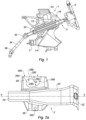
- FIG 1 shows a sectional side view of a dashboard 1 of a motor vehicle, behind which is arranged an air duct 2 according to the present invention.
- the motor vehicle dashboard 1 comprises an upper part 10, supported by a crosspiece 12 and intended in particular to accommodate the various display devices useful for driving the vehicle.
- the dashboard 1 comprises a lower part 14, commonly referred to as the back, shaped to allow the driver's legs to pass and to give access to the vehicle's pedals (not visible on the figure 1 ).
- the dashboard 1 also comprises a passage 16 defining a space accommodating a steering column 3.
- the steering column 3 comprises a first strand 30 fixed to the dashboard 1 and to the crosspiece 12, and is equipped with a steering wheel 4.
- the steering column 3 comprises a first articulation 32, of the universal joint type, connecting the first strand 30 to a second strand 34.
- the steering column 3 comprises a second articulation 36, also of the universal joint type, allowing to connect the second strand 34 to the steering elements controlling the wheels of the motor vehicle, such as a steering rack (not visible on the figure 1 ).
- the second articulation 36 of the second strand 24 is not yet fixed to the steering elements of the vehicle and the second strand 24 of the steering column 3 is thus free, due to the first articulation 32, with respect to the first strand 30 which is fixed to the dashboard 1.
- the air duct 2 is arranged behind the dashboard with respect to the driver and is therefore concealed from the view of the driver by the dashboard 1.
- the air duct 2 is intended to bring the air coming from the air conditioning (or, where applicable, the ventilation system) towards the lower area of the passenger compartment, on the driver's side, that is to say at the level of the driver's feet.
- the air duct 2 is fixed to the dashboard prior to the installation of the latter in the vehicle.
- the air duct 2 in accordance with the invention is described below, in relation to the figures 2a to 2c .
- the air duct 2 comprises a body 20, hollow and elongated along a longitudinal axis YY.
- the body 20 forms an air duct, one end 22 of which is intended to be connected to an air conditioning device (or group).
- the opposite end 24 of the body 20 constitutes an outlet for the air coming from the air conditioning unit and is intended to be placed in the lower zone of the passenger compartment, close to the driver's feet.
- the air duct 2 is intended to be fixed to the dashboard 1 and for this purpose comprises a fixing lug 26.
- the fixing lug 26 comprises a fixing hole 260, allowing the use of a fixing means such as a fixing clip or a plastic rivet.
- the air duct 2 comprises a retaining lug 28, intended to allow the retention of the second strand 34 of the steering column 3, that is to say the strand left free when mounting the dashboard 1 in the passenger compartment of a vehicle.
- the retaining tab 28 includes a notch 280, open at a longitudinal edge 282 free of the retaining tab.
- the notch 280 is shaped so as to allow the insertion and retention of the second strand of the steering column.
- the notch 280 has in the example a general comma shape.
- the notch 280 has two adjacent sectors: an entrance 284, open on the longitudinal edge 282 of the retaining tab 28, and a retaining zone 286, communicating only the entrance 284.
- the entrance 284 of the notch 280 is shaped so as to allow the insertion and extraction of a steering column strand.
- the open end of the inlet 284 has a width L (at the level of the longitudinal edge 282) compatible with the insertion of a steering column strand.
- the width L is between 22.5 and 23.5 millimeters, and in particular equal to 22.9 millimeters.
- the retaining zone 286 is delimited in particular by a retaining tab 288, elongated in a direction substantially parallel to the axis longitudinal YY of the body 20, and forming a return allowing the retention of a steering column strand inserted in the notch 280.
- An outer edge of the retaining tab 288 is constituted by a portion of the longitudinal edge 282 free of the tab retainer 28.
- the opposite edge, or inner edge 290, of retainer tab 288 has a concave shape.
- retaining tab 288 has a bulge 292 at its free end. that is planned to be inserted.
- the bulge 292 makes it possible to generate a hard point during the insertion (and during the extraction) of a steering column strand, a hard point which can be overcome thanks to the elasticity of the retaining tab 288 Thanks to the bulge 292, it is ensured that a steering column strand inserted in the retaining zone 286 cannot be extracted spontaneously.
- the distance D is between 20.5 and 21.5 millimeters, and in particular equal to 20.9 millimeters.
- the retaining lug 28 is arranged in the immediate vicinity, or even facing the fixing lug 26, whether along the longitudinal axis YY ( figure 2a ) or along the vertical axis ZZ ( figure 2c ). This prevents the forces generated by the retention of a steering column strand from involving bending or torsion forces liable to damage the attachment of the air duct 2 to the dashboard 1.
- FIG. 3 shows a steering column strand, such as the second strand 34 of the figure 1 , maintained in the air duct 2 according to the invention.
- the second strand 34 of the steering column 3 is, after insertion by an operator, retained by the retaining tab 288.
- the concave shape of the inner edge 290 of the retaining tab 288, as well as the bulge 292 present on the latter makes it possible to avoid any spontaneous extraction of the strand from the steering column.
- the air duct according to the invention allows the temporary retention of a steering column strand in a reliable and precise manner. Thanks to the invention, it is possible to ensure this maintenance without additional parts, and without waste to be recovered at the end of assembly.
Landscapes
- Engineering & Computer Science (AREA)
- Mechanical Engineering (AREA)
- Physics & Mathematics (AREA)
- Thermal Sciences (AREA)
- Chemical & Material Sciences (AREA)
- Combustion & Propulsion (AREA)
- Transportation (AREA)
- Body Structure For Vehicles (AREA)
- Air-Conditioning For Vehicles (AREA)
- Duct Arrangements (AREA)
Description
- La présente invention se rapporte au domaine de l'assemblage des véhicules automobiles. Elle concerne plus particulièrement l'étape de montage de la planche de bord au sein de l'habitacle d'un véhicule en cours d'assemblage.
Le documentUS6497432 décrit une colonne de direction fixée à un conduit d'air structurel par l'ensemble de fixation 1. - Avant d'être montée dans l'habitacle d'un véhicule, la planche de bord est généralement prééquipée d'une colonne de direction, dont un premier brin, fixé à la planche de bord, est destiné à être connecté à un volant, tandis qu'un deuxième brin, laissé provisoirement libre, est destiné à être raccordé à la crémaillère de direction commandant les roues du véhicule automobile.
- Lors du montage de la planche de bord, il est nécessaire de s'assurer que le brin libre de la colonne ne risque pas de percuter des éléments d'aspect de l'habitacle ou encore des éléments déjà présents, tels que le pédalier. Il est ainsi généralement prévu d'immobiliser temporairement le brin libre de la colonne de direction. Il est connu à cet effet de relier le brin libre de la colonne de direction au corps de la planche de bord, par exemple au moyen d'un élastique ou d'une patte sécable solidaire du corps de planche. Ces deux solutions présentent toutefois l'inconvénient de générer des déchets qui doivent être recyclés une fois que le brin libre de la colonne de direction est libéré. En outre, ces solutions ne sont pas suffisamment fiables, par exemple parce qu'il arrive que la patte sécable soit rompue accidentellement avant même le montage de la planche de bord.
- La présente invention a pour but de remédier aux inconvénients de l'état de la technique, et plus particulièrement ceux ci-dessus exposés, en proposant un dispositif permettant de maintenir temporairement, de manière fiable et simple, le brin de la colonne de direction laissé libre lors du montage de la planche de bord.
- A cet effet, l'invention concerne un ensemble selon la revendication indépendante 1.
- D'autres aspects potentiels de l'invention sont définis par l'objet des revendications dépendantes 2-5.
- L'invention concerne également un véhicule automobile comportant au moins un ensemble selon l'une des revendications 1-5.
- La présente invention sera mieux comprise à la lecture de la description détaillée qui suit, faite en référence aux dessins annexés, dans lesquels :
- la
figure 1 représente une vue latérale en coupe d'une planche de bord d'un véhicule automobile, le véhicule étant équipé d'un conduit d'air conforme à l'invention ; - les
figures 2a ,2b, et 2c représentent différentes vues du conduit d'air de lafigure 1 ; - la
figure 3 est une vue montrant un brin libre de colonne de direction maintenu par un conduit d'air conforme à l'invention. - La
figure 1 représente une vue latérale en coupe d'une planche de bord 1 de véhicule automobile, derrière laquelle est disposé un conduit d'air 2 conforme à la présente invention. La planche de bord 1 de véhicule automobile comporte une partie supérieure 10, supportée par une traverse 12 et destinée notamment à accueillir les divers dispositifs d'affichage utiles pour la conduite du véhicule. La planche de bord 1 comporte une partie inférieure 14, couramment dénommée retour, conformée pour laisser passer les jambes du conducteur et pour donner accès au pédalier du véhicule (non visible sur lafigure 1 ). La planche de bord 1 comporte par ailleurs un passage 16 définissant un espace accueillant une colonne de direction 3. La colonne de direction 3 comporte un premier brin 30 fixé à la planche de bord 1 et à la traverse 12, et est équipée d'un volant 4. La colonne de direction 3 comprend une première articulation 32, de type joint de cardan, reliant le premier brin 30 à un deuxième brin 34. La colonne de direction 3 comporte une deuxième articulation 36, également de type joint de cardan, permettant de relier le deuxième brin 34 aux éléments de direction commandant les roues du véhicule automobile, tels qu'une crémaillère de direction (non visible sur lafigure 1 ). Durant le montage de la planche de bord 1 sur la caisse d'un véhicule automobile, la deuxième articulation 36 du deuxième brin 24 n'est pas encore fixée aux éléments de direction du véhicule et le deuxième brin 24 de la colonne de direction 3 est ainsi libre, du fait de la première articulation 32, par rapport au premier brin 30 qui est fixé à la planche de bord 1. - Le conduit d'air 2 est disposé derrière la planche de bord par rapport au conducteur et est donc dissimulé à la vue du conducteur par la planche de bord 1. Le conduit d'air 2 est destiné à amener l'air provenant du système de climatisation (ou, le cas échéant, du système de ventilation) vers la zone basse de l'habitacle, côté conducteur, c'est-à-dire au niveau des pieds du conducteur. Lors de l'assemblage d'un véhicule, le conduit d'air 2 est fixé à la planche de bord préalablement à l'installation de celle-ci dans le véhicule.
- On décrit ci-après le conduit d'air 2 conforme à l'invention, en relation avec les
figures 2a à 2c . Le conduit d'air 2 comporte un corps 20, creux et allongé selon un axe longitudinal Y-Y. Le corps 20 forme une canalisation d'air dont une extrémité 22 est destinée à être connectée à un dispositif (ou groupe) de climatisation. L'extrémité opposée 24 du corps 20 constitue une sortie pour l'air en provenance du groupe de climatisation et est destinée à être disposée en zone basse de l'habitacle, à proximité des pieds du conducteur. - Le conduit d'air 2 est destiné à être fixé à la planche de bord 1 et comporte à cet effet une patte de fixation 26. La patte de fixation 26 comporte un trou de fixation 260, permettant l'utilisation d'un moyen de fixation tel qu'une agrafe de fixation ou un rivet plastique.
- Du côté opposé à la patte de fixation 26, le conduit d'air 2 comporte une patte de retenue 28, destinée à permettre la rétention du deuxième brin 34 de la colonne de direction 3, c'est-à-dire le brin laissé libre lors du montage de la planche de bord 1 dans l'habitacle d'un véhicule. A cet effet, la patte de retenue 28 comporte une encoche 280, ouverte au niveau d'un bord longitudinal 282 libre de la patte de retenue. L'encoche 280 est conformée de manière à permettre l'insertion et la retenue du deuxième brin de la colonne de direction. L'encoche 280 présente dans l'exemple une forme générale en virgule. L'encoche 280 comporte deux secteurs adjacents : une entrée 284, ouverte sur le bord longitudinal 282 de la patte de retenue 28, et une zone de retenue 286, communiquant uniquement l'entrée 284.
- L'entrée 284 de l'encoche 280 est conformée de manière à permettre l'insertion et l'extraction d'un brin colonne de direction. L'extrémité ouverte de l'entrée 284 présente une largeur L (au niveau du bord longitudinal 282) compatible avec l'insertion d'un brin de colonne de direction. Dans l'exemple la largeur L est comprise entre 22,5 et 23,5 millimètres, et notamment égale à 22,9 millimètres. La zone de retenue 286 est délimitée notamment par une languette de retenue 288, allongée selon une direction sensiblement parallèle à l'axe longitudinal Y-Y du corps 20, et formant un retour permettant la retenue d'un brin de colonne de direction inséré dans l'encoche 280. Un bord extérieur de la languette de retenue 288 est constitué par une portion du bord longitudinal 282 libre de la patte de retenue 28. Le bord opposé, ou bord intérieur 290, de la languette de retenue 288 présente une forme concave. En outre, la languette de retenue 288 comporte à son extrémité libre un renflement 292. Le renflement 292 est dimensionné de manière que la distance D avec le bord opposé de l'encoche 280 soit inférieure ou égale à la largeur du brin de colonne de direction qu'il est prévu d'insérer. Ainsi, le renflement 292 permet de générer un point dur lors de l'insertion (et lors de l'extraction) d'un brin de colonne de direction, point dur qui pourra être dépassé grâce à l'élasticité de la languette de retenue 288. Grâce au renflement 292, on s'assure qu'un brin de colonne de direction inséré dans la zone de retenue 286 ne puisse pas s'extraire spontanément. Dans l'exemple, la distance D est comprise entre 20,5 et 21,5 millimètres, et notamment égale à 20,9 millimètres.
- Avantageusement, comme visible sur les
figures 2a à 2c , la patte de retenue 28 est disposée à proximité immédiate, voire en regard de la patte de fixation 26, que ce soit selon l'axe longitudinal Y-Y (figure 2a ) ou selon l'axe vertical Z-Z (figure 2c ). On évite ainsi que les efforts générés par la retenue d'un brin de colonne de direction n'impliquent pas des efforts de flexion ou de torsion susceptibles d'endommager la fixation du conduit d'air 2 sur la planche de bord 1. - La
figure 3 montre un brin de colonne de direction, tel que le deuxième brin 34 de lafigure 1 , maintenu dans le conduit d'air 2 conforme à l'invention. Comme expliqué plus haut, le deuxième brin 34 de la colonne de direction 3 est, après insertion par un opérateur, retenu par la languette de retenue 288. En particulier, la forme concave du bord intérieur 290 de la languette de retenue 288, ainsi que le renflement 292 présent sur cette dernière permettent d'éviter toute extraction spontanée du brin de la colonne de direction. - Comme on l'a vu, le conduit d'air conforme à l'invention permet la retenue temporaire d'un brin de colonne de direction de manière fiable et précise. Grâce à l'invention, on est en mesure d'assurer ce maintien sans pièce supplémentaire, et sans déchets à récupérer en fin de montage.
Claims (6)
- Ensemble d'une planche de bord (1) de véhicule automobile, d'un brin de colonne, et d'un conduit d'air (2) destiné à être fixé à la planche de bord (1), le conduit d'air (2) comportant un corps (20) allongé selon un axe longitudinal (Y-Y) et formant une canalisation d'air, le conduit d'air (2) comporte une patte de retenue (28) sur laquelle est ménagée une encoche (280), l'encoche (280) comportant une entrée (284) ouverte au niveau d'un bord longitudinal (282) libre de la patte de retenue (28) permettant l'insertion du brin de colonne de direction dans l'encoche (28) et formant un passage vers une zone de retenue (286), la zone de retenue (286) étant délimitée par une languette de retenue (288) allongée selon une direction sensiblement parallèle à l'axe longitudinal (Y-Y) du corps (20), caractérisé en ce que la languette de retenue (288) forme un retour permettant la retenue d'un brin de colonne de direction inséré dans l'encoche (280), de sorte à permettre la retenue du brin de colonne (34) de direction laissé libre lors du montage de la planche de bord, et comporte, à son extrémité libre, un renflement (292), conformé de manière à générer un point dur lors du passage d'un brin de colonne de direction de l'entrée (284) vers la zone de retenue (286) et inversement.
- L'ensemble selon la revendication précédente, dans lequel le renflement (292) est tel que la distance (D) entre l'extrémité libre de la languette de retenue (288) et le bord opposé de l'encoche (280) est inférieure ou égale à la dimension du brin de direction que le conduit d'air (2) est destiné à retenir.
- L'ensemble selon l'une des revendications 1 et 2, dans lequel la languette de retenue (288) est apte à être déformée élastiquement lors du passage d'un brin de direction pour dépasser le point dur généré par le renflement (292).
- L'ensemble selon l'une des revendications 1 à 3, dans lequel la languette de retenue (288) présente un bord extérieur, constitué par une portion du bord longitudinal (282) libre de la patte de retenue (28), et un bord intérieur (290) de forme concave.
- L'ensemble selon l'une des revendications précédentes, le conduit d'air (2) comportant une patte de fixation (26) à une planche de bord (1) d'un véhicule automobile, la patte de retenue (28) étant disposé à proximité immédiate ou en regard de la patte de fixation (26) selon la direction de l'axe longitudinal (Y-Y) du corps (20) du conduit d'air (2).
- Véhicule automobile comportant au moins un ensemble (2) selon l'une des revendications 1 à 5.
Applications Claiming Priority (2)
| Application Number | Priority Date | Filing Date | Title |
|---|---|---|---|
| FR1850074A FR3076498B1 (fr) | 2018-01-05 | 2018-01-05 | Conduit d’air pour planche de bord de vehicule et vehicule comportant un tel conduit. |
| PCT/FR2018/053248 WO2019135037A1 (fr) | 2018-01-05 | 2018-12-13 | Conduit d'air pour planche de bord de vehicule et vehicule comportant un tel conduit |
Publications (2)
| Publication Number | Publication Date |
|---|---|
| EP3735357A1 EP3735357A1 (fr) | 2020-11-11 |
| EP3735357B1 true EP3735357B1 (fr) | 2023-04-05 |
Family
ID=61599460
Family Applications (1)
| Application Number | Title | Priority Date | Filing Date |
|---|---|---|---|
| EP18839825.9A Active EP3735357B1 (fr) | 2018-01-05 | 2018-12-13 | Ensemble d'une planche de bord, d'un brin de colonne et d'un conduit d'air |
Country Status (4)
| Country | Link |
|---|---|
| EP (1) | EP3735357B1 (fr) |
| FR (1) | FR3076498B1 (fr) |
| PL (1) | PL3735357T3 (fr) |
| WO (1) | WO2019135037A1 (fr) |
Citations (3)
| Publication number | Priority date | Publication date | Assignee | Title |
|---|---|---|---|---|
| JPS61166718A (ja) * | 1985-01-21 | 1986-07-28 | Nissan Motor Co Ltd | ダクトの取付構造 |
| US6497432B2 (en) * | 2000-02-22 | 2002-12-24 | Delphi Technologies, Inc. | Structural attachment system and method for a vehicle |
| DE102011007668A1 (de) * | 2011-04-19 | 2012-11-08 | Johnson Controls Interiors Gmbh & Co. Kg | Instrumententafel für ein Fahrzeug |
Family Cites Families (3)
| Publication number | Priority date | Publication date | Assignee | Title |
|---|---|---|---|---|
| JP3094053B2 (ja) * | 1994-02-25 | 2000-10-03 | 富士機工株式会社 | 車両用ステアリング装置 |
| WO2001068392A1 (fr) * | 2000-03-13 | 2001-09-20 | Zexel Valeo Climate Control Corporation | Systeme de climatisation d'automobile |
| US20050151361A1 (en) * | 2004-01-14 | 2005-07-14 | Mazda Motor Corporation | Steering support structure of vehicle |
-
2018
- 2018-01-05 FR FR1850074A patent/FR3076498B1/fr not_active Expired - Fee Related
- 2018-12-13 EP EP18839825.9A patent/EP3735357B1/fr active Active
- 2018-12-13 WO PCT/FR2018/053248 patent/WO2019135037A1/fr not_active Ceased
- 2018-12-13 PL PL18839825.9T patent/PL3735357T3/pl unknown
Patent Citations (3)
| Publication number | Priority date | Publication date | Assignee | Title |
|---|---|---|---|---|
| JPS61166718A (ja) * | 1985-01-21 | 1986-07-28 | Nissan Motor Co Ltd | ダクトの取付構造 |
| US6497432B2 (en) * | 2000-02-22 | 2002-12-24 | Delphi Technologies, Inc. | Structural attachment system and method for a vehicle |
| DE102011007668A1 (de) * | 2011-04-19 | 2012-11-08 | Johnson Controls Interiors Gmbh & Co. Kg | Instrumententafel für ein Fahrzeug |
Also Published As
| Publication number | Publication date |
|---|---|
| WO2019135037A1 (fr) | 2019-07-11 |
| EP3735357A1 (fr) | 2020-11-11 |
| PL3735357T3 (pl) | 2023-06-12 |
| FR3076498A1 (fr) | 2019-07-12 |
| FR3076498B1 (fr) | 2020-10-23 |
Similar Documents
| Publication | Publication Date | Title |
|---|---|---|
| FR3107678A1 (fr) | Agencement de pare-chocs | |
| EP4247647B1 (fr) | Enjoliveur pour une roue en tôle, roue en tôle comportant un tel enjoliveur et véhicule comportant une telle roue | |
| EP2062804B1 (fr) | Dispositif et procédé de fixation d'un ensemble d'aile sur une paroi de caisse d'un véhicule automobile | |
| EP3095684A1 (fr) | Patte de derailleur | |
| EP3735357B1 (fr) | Ensemble d'une planche de bord, d'un brin de colonne et d'un conduit d'air | |
| EP3114012B1 (fr) | Assemblage d'un cockpit et d'une structure de vehicule automobile et procede de montage correspondant | |
| EP1574422B1 (fr) | Traverse pour véhicule automobile et véhicule associé | |
| EP2008918B1 (fr) | Garde-boue de véhicule automobile et véhicule automobile associé | |
| EP2173604B1 (fr) | Agencement de fixation de deux elements de carrosserie adjacents | |
| EP3792153B1 (fr) | Véhicule doté d'un déflecteur | |
| EP2785563B1 (fr) | Agencement d'une garniture latérale de coffre | |
| FR3139774A1 (fr) | Enjoliveur latéral pour pare-chocs de véhicule automobile, pare-chocs de véhicule automobile comportant un tel enjoliveur latéral et véhicule automobile comportant un tel pare-chocs | |
| EP2670631B1 (fr) | Ensemble et procede pour maintenir un pare-chocs et vehicule comprenant un tel ensemble. | |
| FR2784955A1 (fr) | Dispositif de fixation d'un element exterieur de carrosserie sur une structure de vehicule, et vehicule comportant un tel dispositif | |
| EP1718100B1 (fr) | Agencement d'une grille de haut-parleur | |
| EP1934081B1 (fr) | Dispositif d'habillage d'une colonne de direction | |
| EP1877284B1 (fr) | Agencement pour le montage d'un bouclier de vehicule automobile | |
| FR2908847A1 (fr) | Ensemble pour vehicule automobile,notamment pour l'assemblage d'une aile et d'un elargisseur d'aile. | |
| WO2024069071A1 (fr) | Enjoliveur pour une roue en tole a montage simplifie | |
| EP2045171B1 (fr) | Module avant de véhicule automobile et procédé de montage associé | |
| FR3138080A1 (fr) | Piece pour vehicule automobile | |
| FR3152482A1 (fr) | Dispositif de fixation de pièces plastiques pour véhicule automobile et véhicule comprenant un tel dispositif | |
| FR2874584A1 (fr) | Module de vehicule automobile comportant des moyens de positionnement perfectionnes sur la caisse du vehicule automobile | |
| WO2024115829A1 (fr) | Pare-chocs de véhicule automobile, face avant comportant un tel pare-chocs et véhicule automobile comportant une telle face avant | |
| FR3096021A1 (fr) | Caisse de véhicule automobile équipée d'une planche de bord positionnée en butée transversale contre un élément de carrosserie. |
Legal Events
| Date | Code | Title | Description |
|---|---|---|---|
| STAA | Information on the status of an ep patent application or granted ep patent |
Free format text: STATUS: UNKNOWN |
|
| STAA | Information on the status of an ep patent application or granted ep patent |
Free format text: STATUS: THE INTERNATIONAL PUBLICATION HAS BEEN MADE |
|
| PUAI | Public reference made under article 153(3) epc to a published international application that has entered the european phase |
Free format text: ORIGINAL CODE: 0009012 |
|
| STAA | Information on the status of an ep patent application or granted ep patent |
Free format text: STATUS: REQUEST FOR EXAMINATION WAS MADE |
|
| 17P | Request for examination filed |
Effective date: 20200723 |
|
| AK | Designated contracting states |
Kind code of ref document: A1 Designated state(s): AL AT BE BG CH CY CZ DE DK EE ES FI FR GB GR HR HU IE IS IT LI LT LU LV MC MK MT NL NO PL PT RO RS SE SI SK SM TR |
|
| AX | Request for extension of the european patent |
Extension state: BA ME |
|
| DAV | Request for validation of the european patent (deleted) | ||
| DAX | Request for extension of the european patent (deleted) | ||
| STAA | Information on the status of an ep patent application or granted ep patent |
Free format text: STATUS: EXAMINATION IS IN PROGRESS |
|
| 17Q | First examination report despatched |
Effective date: 20210818 |
|
| REG | Reference to a national code |
Ref country code: DE Ref legal event code: R079 Ref document number: 602018048164 Country of ref document: DE Free format text: PREVIOUS MAIN CLASS: B60H0001000000 Ipc: B60K0013060000 |
|
| RIC1 | Information provided on ipc code assigned before grant |
Ipc: B62D 1/16 20060101ALN20221021BHEP Ipc: B60H 1/24 20060101ALN20221021BHEP Ipc: B60H 1/00 20060101ALN20221021BHEP Ipc: B60K 13/06 20060101AFI20221021BHEP |
|
| GRAP | Despatch of communication of intention to grant a patent |
Free format text: ORIGINAL CODE: EPIDOSNIGR1 |
|
| STAA | Information on the status of an ep patent application or granted ep patent |
Free format text: STATUS: GRANT OF PATENT IS INTENDED |
|
| RIC1 | Information provided on ipc code assigned before grant |
Ipc: B62D 1/16 20060101ALN20221104BHEP Ipc: B60H 1/24 20060101ALN20221104BHEP Ipc: B60H 1/00 20060101ALN20221104BHEP Ipc: B60K 13/06 20060101AFI20221104BHEP |
|
| RIC1 | Information provided on ipc code assigned before grant |
Ipc: B62D 1/16 20060101ALN20221117BHEP Ipc: B60H 1/24 20060101ALN20221117BHEP Ipc: B60H 1/00 20060101ALN20221117BHEP Ipc: B60K 13/06 20060101AFI20221117BHEP |
|
| RIC1 | Information provided on ipc code assigned before grant |
Ipc: B62D 1/16 20060101ALN20221125BHEP Ipc: B60H 1/24 20060101ALN20221125BHEP Ipc: B60H 1/00 20060101ALN20221125BHEP Ipc: B60K 13/06 20060101AFI20221125BHEP |
|
| INTG | Intention to grant announced |
Effective date: 20221212 |
|
| RIN1 | Information on inventor provided before grant (corrected) |
Inventor name: MITOUART, JEAN GUY |
|
| GRAS | Grant fee paid |
Free format text: ORIGINAL CODE: EPIDOSNIGR3 |
|
| GRAA | (expected) grant |
Free format text: ORIGINAL CODE: 0009210 |
|
| STAA | Information on the status of an ep patent application or granted ep patent |
Free format text: STATUS: THE PATENT HAS BEEN GRANTED |
|
| AK | Designated contracting states |
Kind code of ref document: B1 Designated state(s): AL AT BE BG CH CY CZ DE DK EE ES FI FR GB GR HR HU IE IS IT LI LT LU LV MC MK MT NL NO PL PT RO RS SE SI SK SM TR |
|
| REG | Reference to a national code |
Ref country code: GB Ref legal event code: FG4D Free format text: NOT ENGLISH |
|
| REG | Reference to a national code |
Ref country code: DE Ref legal event code: R096 Ref document number: 602018048164 Country of ref document: DE |
|
| REG | Reference to a national code |
Ref country code: CH Ref legal event code: EP |
|
| REG | Reference to a national code |
Ref country code: AT Ref legal event code: REF Ref document number: 1557974 Country of ref document: AT Kind code of ref document: T Effective date: 20230415 |
|
| REG | Reference to a national code |
Ref country code: IE Ref legal event code: FG4D Free format text: LANGUAGE OF EP DOCUMENT: FRENCH |
|
| REG | Reference to a national code |
Ref country code: GB Ref legal event code: 746 Effective date: 20230509 |
|
| REG | Reference to a national code |
Ref country code: DE Ref legal event code: R084 Ref document number: 602018048164 Country of ref document: DE |
|
| REG | Reference to a national code |
Ref country code: LT Ref legal event code: MG9D |
|
| REG | Reference to a national code |
Ref country code: NL Ref legal event code: MP Effective date: 20230405 |
|
| REG | Reference to a national code |
Ref country code: AT Ref legal event code: MK05 Ref document number: 1557974 Country of ref document: AT Kind code of ref document: T Effective date: 20230405 |
|
| PG25 | Lapsed in a contracting state [announced via postgrant information from national office to epo] |
Ref country code: NL Free format text: LAPSE BECAUSE OF FAILURE TO SUBMIT A TRANSLATION OF THE DESCRIPTION OR TO PAY THE FEE WITHIN THE PRESCRIBED TIME-LIMIT Effective date: 20230405 |
|
| PG25 | Lapsed in a contracting state [announced via postgrant information from national office to epo] |
Ref country code: SE Free format text: LAPSE BECAUSE OF FAILURE TO SUBMIT A TRANSLATION OF THE DESCRIPTION OR TO PAY THE FEE WITHIN THE PRESCRIBED TIME-LIMIT Effective date: 20230405 Ref country code: PT Free format text: LAPSE BECAUSE OF FAILURE TO SUBMIT A TRANSLATION OF THE DESCRIPTION OR TO PAY THE FEE WITHIN THE PRESCRIBED TIME-LIMIT Effective date: 20230807 Ref country code: NO Free format text: LAPSE BECAUSE OF FAILURE TO SUBMIT A TRANSLATION OF THE DESCRIPTION OR TO PAY THE FEE WITHIN THE PRESCRIBED TIME-LIMIT Effective date: 20230705 Ref country code: ES Free format text: LAPSE BECAUSE OF FAILURE TO SUBMIT A TRANSLATION OF THE DESCRIPTION OR TO PAY THE FEE WITHIN THE PRESCRIBED TIME-LIMIT Effective date: 20230405 Ref country code: AT Free format text: LAPSE BECAUSE OF FAILURE TO SUBMIT A TRANSLATION OF THE DESCRIPTION OR TO PAY THE FEE WITHIN THE PRESCRIBED TIME-LIMIT Effective date: 20230405 |
|
| PG25 | Lapsed in a contracting state [announced via postgrant information from national office to epo] |
Ref country code: RS Free format text: LAPSE BECAUSE OF FAILURE TO SUBMIT A TRANSLATION OF THE DESCRIPTION OR TO PAY THE FEE WITHIN THE PRESCRIBED TIME-LIMIT Effective date: 20230405 Ref country code: LV Free format text: LAPSE BECAUSE OF FAILURE TO SUBMIT A TRANSLATION OF THE DESCRIPTION OR TO PAY THE FEE WITHIN THE PRESCRIBED TIME-LIMIT Effective date: 20230405 Ref country code: LT Free format text: LAPSE BECAUSE OF FAILURE TO SUBMIT A TRANSLATION OF THE DESCRIPTION OR TO PAY THE FEE WITHIN THE PRESCRIBED TIME-LIMIT Effective date: 20230405 Ref country code: IS Free format text: LAPSE BECAUSE OF FAILURE TO SUBMIT A TRANSLATION OF THE DESCRIPTION OR TO PAY THE FEE WITHIN THE PRESCRIBED TIME-LIMIT Effective date: 20230805 Ref country code: HR Free format text: LAPSE BECAUSE OF FAILURE TO SUBMIT A TRANSLATION OF THE DESCRIPTION OR TO PAY THE FEE WITHIN THE PRESCRIBED TIME-LIMIT Effective date: 20230405 Ref country code: GR Free format text: LAPSE BECAUSE OF FAILURE TO SUBMIT A TRANSLATION OF THE DESCRIPTION OR TO PAY THE FEE WITHIN THE PRESCRIBED TIME-LIMIT Effective date: 20230706 Ref country code: AL Free format text: LAPSE BECAUSE OF FAILURE TO SUBMIT A TRANSLATION OF THE DESCRIPTION OR TO PAY THE FEE WITHIN THE PRESCRIBED TIME-LIMIT Effective date: 20230405 |
|
| RAP4 | Party data changed (patent owner data changed or rights of a patent transferred) |
Owner name: STELLANTIS AUTO SAS |
|
| PG25 | Lapsed in a contracting state [announced via postgrant information from national office to epo] |
Ref country code: FI Free format text: LAPSE BECAUSE OF FAILURE TO SUBMIT A TRANSLATION OF THE DESCRIPTION OR TO PAY THE FEE WITHIN THE PRESCRIBED TIME-LIMIT Effective date: 20230405 |
|
| REG | Reference to a national code |
Ref country code: DE Ref legal event code: R097 Ref document number: 602018048164 Country of ref document: DE |
|
| PG25 | Lapsed in a contracting state [announced via postgrant information from national office to epo] |
Ref country code: SK Free format text: LAPSE BECAUSE OF FAILURE TO SUBMIT A TRANSLATION OF THE DESCRIPTION OR TO PAY THE FEE WITHIN THE PRESCRIBED TIME-LIMIT Effective date: 20230405 |
|
| PG25 | Lapsed in a contracting state [announced via postgrant information from national office to epo] |
Ref country code: SM Free format text: LAPSE BECAUSE OF FAILURE TO SUBMIT A TRANSLATION OF THE DESCRIPTION OR TO PAY THE FEE WITHIN THE PRESCRIBED TIME-LIMIT Effective date: 20230405 Ref country code: SK Free format text: LAPSE BECAUSE OF FAILURE TO SUBMIT A TRANSLATION OF THE DESCRIPTION OR TO PAY THE FEE WITHIN THE PRESCRIBED TIME-LIMIT Effective date: 20230405 Ref country code: RO Free format text: LAPSE BECAUSE OF FAILURE TO SUBMIT A TRANSLATION OF THE DESCRIPTION OR TO PAY THE FEE WITHIN THE PRESCRIBED TIME-LIMIT Effective date: 20230405 Ref country code: EE Free format text: LAPSE BECAUSE OF FAILURE TO SUBMIT A TRANSLATION OF THE DESCRIPTION OR TO PAY THE FEE WITHIN THE PRESCRIBED TIME-LIMIT Effective date: 20230405 Ref country code: DK Free format text: LAPSE BECAUSE OF FAILURE TO SUBMIT A TRANSLATION OF THE DESCRIPTION OR TO PAY THE FEE WITHIN THE PRESCRIBED TIME-LIMIT Effective date: 20230405 Ref country code: CZ Free format text: LAPSE BECAUSE OF FAILURE TO SUBMIT A TRANSLATION OF THE DESCRIPTION OR TO PAY THE FEE WITHIN THE PRESCRIBED TIME-LIMIT Effective date: 20230405 |
|
| PLBE | No opposition filed within time limit |
Free format text: ORIGINAL CODE: 0009261 |
|
| STAA | Information on the status of an ep patent application or granted ep patent |
Free format text: STATUS: NO OPPOSITION FILED WITHIN TIME LIMIT |
|
| 26N | No opposition filed |
Effective date: 20240108 |
|
| REG | Reference to a national code |
Ref country code: DE Ref legal event code: R081 Ref document number: 602018048164 Country of ref document: DE Owner name: STELLANTIS AUTO SAS, FR Free format text: FORMER OWNER: PSA AUTOMOBILES SA, POISSY, FR |
|
| PG25 | Lapsed in a contracting state [announced via postgrant information from national office to epo] |
Ref country code: SI Free format text: LAPSE BECAUSE OF FAILURE TO SUBMIT A TRANSLATION OF THE DESCRIPTION OR TO PAY THE FEE WITHIN THE PRESCRIBED TIME-LIMIT Effective date: 20230405 |
|
| PG25 | Lapsed in a contracting state [announced via postgrant information from national office to epo] |
Ref country code: SI Free format text: LAPSE BECAUSE OF FAILURE TO SUBMIT A TRANSLATION OF THE DESCRIPTION OR TO PAY THE FEE WITHIN THE PRESCRIBED TIME-LIMIT Effective date: 20230405 |
|
| REG | Reference to a national code |
Ref country code: CH Ref legal event code: PL |
|
| PG25 | Lapsed in a contracting state [announced via postgrant information from national office to epo] |
Ref country code: LU Free format text: LAPSE BECAUSE OF NON-PAYMENT OF DUE FEES Effective date: 20231213 |
|
| PG25 | Lapsed in a contracting state [announced via postgrant information from national office to epo] |
Ref country code: MC Free format text: LAPSE BECAUSE OF FAILURE TO SUBMIT A TRANSLATION OF THE DESCRIPTION OR TO PAY THE FEE WITHIN THE PRESCRIBED TIME-LIMIT Effective date: 20230405 |
|
| REG | Reference to a national code |
Ref country code: BE Ref legal event code: MM Effective date: 20231231 |
|
| PG25 | Lapsed in a contracting state [announced via postgrant information from national office to epo] |
Ref country code: MC Free format text: LAPSE BECAUSE OF FAILURE TO SUBMIT A TRANSLATION OF THE DESCRIPTION OR TO PAY THE FEE WITHIN THE PRESCRIBED TIME-LIMIT Effective date: 20230405 Ref country code: LU Free format text: LAPSE BECAUSE OF NON-PAYMENT OF DUE FEES Effective date: 20231213 |
|
| REG | Reference to a national code |
Ref country code: IE Ref legal event code: MM4A |
|
| PG25 | Lapsed in a contracting state [announced via postgrant information from national office to epo] |
Ref country code: IE Free format text: LAPSE BECAUSE OF NON-PAYMENT OF DUE FEES Effective date: 20231213 |
|
| PG25 | Lapsed in a contracting state [announced via postgrant information from national office to epo] |
Ref country code: BE Free format text: LAPSE BECAUSE OF NON-PAYMENT OF DUE FEES Effective date: 20231231 |
|
| PG25 | Lapsed in a contracting state [announced via postgrant information from national office to epo] |
Ref country code: CH Free format text: LAPSE BECAUSE OF NON-PAYMENT OF DUE FEES Effective date: 20231231 |
|
| PG25 | Lapsed in a contracting state [announced via postgrant information from national office to epo] |
Ref country code: IE Free format text: LAPSE BECAUSE OF NON-PAYMENT OF DUE FEES Effective date: 20231213 Ref country code: CH Free format text: LAPSE BECAUSE OF NON-PAYMENT OF DUE FEES Effective date: 20231231 Ref country code: BE Free format text: LAPSE BECAUSE OF NON-PAYMENT OF DUE FEES Effective date: 20231231 |
|
| PG25 | Lapsed in a contracting state [announced via postgrant information from national office to epo] |
Ref country code: BG Free format text: LAPSE BECAUSE OF FAILURE TO SUBMIT A TRANSLATION OF THE DESCRIPTION OR TO PAY THE FEE WITHIN THE PRESCRIBED TIME-LIMIT Effective date: 20230405 |
|
| PG25 | Lapsed in a contracting state [announced via postgrant information from national office to epo] |
Ref country code: BG Free format text: LAPSE BECAUSE OF FAILURE TO SUBMIT A TRANSLATION OF THE DESCRIPTION OR TO PAY THE FEE WITHIN THE PRESCRIBED TIME-LIMIT Effective date: 20230405 |
|
| PG25 | Lapsed in a contracting state [announced via postgrant information from national office to epo] |
Ref country code: CY Free format text: LAPSE BECAUSE OF FAILURE TO SUBMIT A TRANSLATION OF THE DESCRIPTION OR TO PAY THE FEE WITHIN THE PRESCRIBED TIME-LIMIT; INVALID AB INITIO Effective date: 20181213 |
|
| PG25 | Lapsed in a contracting state [announced via postgrant information from national office to epo] |
Ref country code: HU Free format text: LAPSE BECAUSE OF FAILURE TO SUBMIT A TRANSLATION OF THE DESCRIPTION OR TO PAY THE FEE WITHIN THE PRESCRIBED TIME-LIMIT; INVALID AB INITIO Effective date: 20181213 |
|
| PG25 | Lapsed in a contracting state [announced via postgrant information from national office to epo] |
Ref country code: TR Free format text: LAPSE BECAUSE OF FAILURE TO SUBMIT A TRANSLATION OF THE DESCRIPTION OR TO PAY THE FEE WITHIN THE PRESCRIBED TIME-LIMIT Effective date: 20230405 |
|
| PGFP | Annual fee paid to national office [announced via postgrant information from national office to epo] |
Ref country code: DE Payment date: 20251126 Year of fee payment: 8 |
|
| PGFP | Annual fee paid to national office [announced via postgrant information from national office to epo] |
Ref country code: GB Payment date: 20251119 Year of fee payment: 8 |
|
| PGFP | Annual fee paid to national office [announced via postgrant information from national office to epo] |
Ref country code: IT Payment date: 20251119 Year of fee payment: 8 |
|
| PGFP | Annual fee paid to national office [announced via postgrant information from national office to epo] |
Ref country code: FR Payment date: 20251120 Year of fee payment: 8 |
|
| PGFP | Annual fee paid to national office [announced via postgrant information from national office to epo] |
Ref country code: PL Payment date: 20251124 Year of fee payment: 8 |