EP3734951A1 - Display control method, information processing server and display terminal - Google Patents
Display control method, information processing server and display terminal Download PDFInfo
- Publication number
- EP3734951A1 EP3734951A1 EP18896838.2A EP18896838A EP3734951A1 EP 3734951 A1 EP3734951 A1 EP 3734951A1 EP 18896838 A EP18896838 A EP 18896838A EP 3734951 A1 EP3734951 A1 EP 3734951A1
- Authority
- EP
- European Patent Office
- Prior art keywords
- item
- user
- suggestion
- information
- information processing
- Prior art date
- Legal status (The legal status is an assumption and is not a legal conclusion. Google has not performed a legal analysis and makes no representation as to the accuracy of the status listed.)
- Granted
Links
Images





Classifications
-
- H—ELECTRICITY
- H04—ELECTRIC COMMUNICATION TECHNIQUE
- H04N—PICTORIAL COMMUNICATION, e.g. TELEVISION
- H04N7/00—Television systems
- H04N7/18—Closed-circuit television [CCTV] systems, i.e. systems in which the video signal is not broadcast
- H04N7/183—Closed-circuit television [CCTV] systems, i.e. systems in which the video signal is not broadcast for receiving images from a single remote source
- H04N7/186—Video door telephones
-
- H—ELECTRICITY
- H04—ELECTRIC COMMUNICATION TECHNIQUE
- H04M—TELEPHONIC COMMUNICATION
- H04M9/00—Arrangements for interconnection not involving centralised switching
- H04M9/02—Arrangements for interconnection not involving centralised switching involving a common line for all parties
-
- G—PHYSICS
- G07—CHECKING-DEVICES
- G07C—TIME OR ATTENDANCE REGISTERS; REGISTERING OR INDICATING THE WORKING OF MACHINES; GENERATING RANDOM NUMBERS; VOTING OR LOTTERY APPARATUS; ARRANGEMENTS, SYSTEMS OR APPARATUS FOR CHECKING NOT PROVIDED FOR ELSEWHERE
- G07C9/00—Individual registration on entry or exit
- G07C9/00174—Electronically operated locks; Circuits therefor; Nonmechanical keys therefor, e.g. passive or active electrical keys or other data carriers without mechanical keys
- G07C9/00571—Electronically operated locks; Circuits therefor; Nonmechanical keys therefor, e.g. passive or active electrical keys or other data carriers without mechanical keys operated by interacting with a central unit
-
- G—PHYSICS
- G07—CHECKING-DEVICES
- G07C—TIME OR ATTENDANCE REGISTERS; REGISTERING OR INDICATING THE WORKING OF MACHINES; GENERATING RANDOM NUMBERS; VOTING OR LOTTERY APPARATUS; ARRANGEMENTS, SYSTEMS OR APPARATUS FOR CHECKING NOT PROVIDED FOR ELSEWHERE
- G07C9/00—Individual registration on entry or exit
- G07C9/00174—Electronically operated locks; Circuits therefor; Nonmechanical keys therefor, e.g. passive or active electrical keys or other data carriers without mechanical keys
- G07C9/00896—Electronically operated locks; Circuits therefor; Nonmechanical keys therefor, e.g. passive or active electrical keys or other data carriers without mechanical keys specially adapted for particular uses
-
- G—PHYSICS
- G07—CHECKING-DEVICES
- G07C—TIME OR ATTENDANCE REGISTERS; REGISTERING OR INDICATING THE WORKING OF MACHINES; GENERATING RANDOM NUMBERS; VOTING OR LOTTERY APPARATUS; ARRANGEMENTS, SYSTEMS OR APPARATUS FOR CHECKING NOT PROVIDED FOR ELSEWHERE
- G07C9/00—Individual registration on entry or exit
- G07C9/00174—Electronically operated locks; Circuits therefor; Nonmechanical keys therefor, e.g. passive or active electrical keys or other data carriers without mechanical keys
- G07C9/00896—Electronically operated locks; Circuits therefor; Nonmechanical keys therefor, e.g. passive or active electrical keys or other data carriers without mechanical keys specially adapted for particular uses
- G07C9/00904—Electronically operated locks; Circuits therefor; Nonmechanical keys therefor, e.g. passive or active electrical keys or other data carriers without mechanical keys specially adapted for particular uses for hotels, motels, office buildings or the like
-
- H—ELECTRICITY
- H04—ELECTRIC COMMUNICATION TECHNIQUE
- H04L—TRANSMISSION OF DIGITAL INFORMATION, e.g. TELEGRAPHIC COMMUNICATION
- H04L12/00—Data switching networks
- H04L12/28—Data switching networks characterised by path configuration, e.g. LAN [Local Area Networks] or WAN [Wide Area Networks]
- H04L12/2803—Home automation networks
- H04L12/2816—Controlling appliance services of a home automation network by calling their functionalities
- H04L12/282—Controlling appliance services of a home automation network by calling their functionalities based on user interaction within the home
-
- H—ELECTRICITY
- H04—ELECTRIC COMMUNICATION TECHNIQUE
- H04L—TRANSMISSION OF DIGITAL INFORMATION, e.g. TELEGRAPHIC COMMUNICATION
- H04L12/00—Data switching networks
- H04L12/28—Data switching networks characterised by path configuration, e.g. LAN [Local Area Networks] or WAN [Wide Area Networks]
- H04L12/2803—Home automation networks
- H04L2012/2847—Home automation networks characterised by the type of home appliance used
- H04L2012/285—Generic home appliances, e.g. refrigerators
Definitions
- the present disclosure relates to a display control method, an information processing server, and a display terminal for controlling display of a suggestion regarding reception of an item from a delivery person who delivers the item to a building in which a user is present.
- Patent Literature (PTL) 1 discloses a video door phone device for stable wireless communication between an indoor master unit and an entrance slave unit. With such a video door phone device, when, for example, a delivery person arrives at the door of a building and activates an intercom, an image of the delivery person captured by the entrance slave unit is displayed on the display of the indoor master unit.
- the indoor master unit only displays the image of the delivery person, and thus, it is not possible to effectively present the user with information which assists the user in determining the next action.
- the present disclosure provides a display control method and the related technologies capable of effectively presenting a user with information which assists the user in determining the next action when a delivery person arrives with a delivery item.
- a display control method is a display control method performed using a system including an information processing server, and the display control method includes: (a) obtaining, by the information processing server, using a sensor, a user state indicating whether a user is currently cooking using a cooker, when an image of a delivery person delivering an item to a building in which the user is present is captured by a camera provided at an entrance door of the building; (b) obtaining, by the information processing server, content information of the item; (c) obtaining, by the information processing server, at least one suggestion associated with the user state and the content information of the item; and (d) causing, by the information processing server, a display terminal provided in the building to display the image of the delivery person, the content information of the item, and the at least one suggestion.
- a display control method is capable of effectively presenting a user with information which assists the user in determining the next action when a delivery person arrives with a delivery item.
- an information processing system and method according to the present disclosure provide the user with information about the delivery to make it easier for the user to determine the action that the user wants to take. Additionally, an information processing system and method according to the present disclosure simplify the user's action by providing the user with a suggestion to expedite the user's action, and controlling devices according to the user's response to the suggestion displayed. That is to say, the inventor has conceived an information processing system and method which display, on one screen, both information about the delivery and a suggestion for expediting the user's action, to facilitate both the user's understanding of the situation and the user's action.
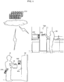
- FIG. 1 is an external view of an information processing system and peripheral devices according to Embodiment 1.
- FIG. 2 is a block diagram illustrating a functional configuration of the information processing system according to Embodiment 1.
- Information processing system 10 includes information processing server 100 and one or more display terminals including display terminal 200.
- Information processing server 100 and one or more display terminals are communicably connected to one another.
- display terminal 200 will be described as a representative of the one or more display terminals, and description of the rest of the display terminals will be omitted.
- Information processing system 10 is communicably connected to camera 300, electronic lock 400, information terminal 500, cooker 600, sensor 700, first database 801, second database 802, and third database 803.
- Information processing server 100 is, for example, a cloud server, and causes display terminal 200 to display at least one suggestion based on a user state.
- Display terminal 200 includes a display, and displays, on the display, at least one suggestion received from information processing server 100.
- display terminal 200 is provided on a wall surface in a building.
- display terminal 200 may be a mobile terminal.
- Camera 300 is provided at entrance door 30 of the building.
- camera 300 is built into a door phone.
- camera 300 captures an image of delivery person 50 who delivers item 40 to the building in which user 20 is present.
- the building includes, for example, a residence, an apartment building, an office building having a plurality of offices, a commercial building having a plurality of shops, and a hotel having a plurality of rooms.
- Entrance door 30 of an apartment building may be an entrance door of each residence, or may be an entrance door of the apartment building.
- Entrance door 30 of an office building may be an entrance door of each office, or may be an entrance door of the office building.
- entrance door 30 of a commercial building may be an entrance door of each shop, or may be an entrance door of the commercial building.
- Electronic lock 400 is a lock capable of remote control on the opening and closing of entrance door 30 of the building.
- Electronic lock 400 is also referred to as an electronic key.
- Electronic lock 400 controls the opening and closing of entrance door 30 based on a lock/unlock signal from information processing system 10.
- Information terminal 500 is a terminal usable by delivery person 50.
- Information terminal 500 is a handy terminal carried by delivery person 50, for example.
- Information terminal 500 receives a request for redelivery of item 40 from information processing system 10.
- Information terminal 500 may be provided at entrance door 30, for example.
- Cooker 600 is a device used when user 20 cooks.
- Cooker 600 is, for example, a microwave oven, a cooking stove, or the like.
- Cooker 600 can control power ON and OFF based on a signal from information processing system 10.
- Sensor 700 transmits to information processing system 10 a sensor value used for obtaining a user state indicating whether user 20 is currently cooking using cooker 600.
- sensor 700 is, for example, an image sensor which is provided in the building and captures an image of the inside of the building.
- Sensor 700 may be, for example, an ON/OFF sensor which detects power ON and OFF of cooker 600.
- First database 801 is a storage device storing first data 801a which associates sensor values and user states for each of a plurality of users.
- first database 801 is, for example, a database server which includes a processor, memory, and a hard disk drive.
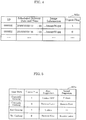
- FIG. 3 illustrates an example of first data 801a according to Embodiment 1.
- first data 801a includes user information, sensor value, and user state.
- User information is information that identifies users.
- Sensor value represents an image pattern, for example.
- User state indicates whether a user is currently cooking. According to first data 801a in FIG. 3 , the user state is determined to be cooking when Pattern 1 is included in an image of the user identified as USER 1.
- Second database 802 is a storage device storing second data 802a which associates (i) a plurality of pieces of identification information or a plurality of scheduled delivery dates and times and (ii) pieces of content information of a plurality of items.
- second database 802 is, for example, a database server which includes a processor, memory, and a hard disk drive.
- FIG. 4 illustrates an example of second data 802a according to Embodiment 1.
- second data 802a includes ID, scheduled delivery date and time, image information, and urgent flag.
- ID is an example of identification information for identifying content information.
- Scheduled delivery date and time indicates a date and time of scheduled delivery of an item.
- Image information is identifier information which identifies an image of an item (for example, a uniform resource identifier (URI)).
- Urgent flag is an example of urgent information indicating whether the delivery of the item is urgent.
- the urgent flag is set by the user when the user purchases an item via a website.
- urgent flag 1 indicates that the delivery is urgent
- urgent flag 0 indicates that the delivery is non-urgent.
- the image information and the urgent flag correspond to the content information of the item.
- second data 802a in FIG. 4 It can be seen from second data 802a in FIG. 4 that, for example, the image of an item identified by 000001 is .../image01.jpg, and that the delivery of this item is urgent. It can also be seen that the image of an item scheduled to be delivered on 2018/10/30 at 12:00 is .../image01.jpg, and that the delivery of this item is urgent.
- Third database 803 is a storage device storing third data 803a which associates (i) a plurality of combinations of a user state and content information of an item and (ii) a plurality of suggestion sets each including at least one suggestion.
- third database 803 is, for example, a database server which includes a processor, memory, and a hard disk drive.
- FIG. 5 illustrates an example of third data 803a according to Embodiment 1.
- Third data 803a in FIG. 5 includes user state, urgent flag, first suggestion, and second suggestion.
- User state indicates whether the user is currently cooking.
- urgent flag is an example of urgent information indicating whether the delivery of the item is urgent.
- third data 803a in FIG. 5 when, for example, the user state is Cooking and the urgent information indicates Yes, the first suggestion of Cooker OFF and the second suggestion of Unlock are obtained.
- information processing server 100 includes processor 101, memory 102, and communication unit 103.
- Processor 101 is an electric circuit connected to memory 102.
- processor 101 obtains, using sensor 700, a user state indicating whether user 20 is currently cooking using cooker 600.
- Processor 101 further obtains content information of item 40.
- Processor 101 then obtains at least one suggestion associated with the user state, and causes display terminal 200 to display the image of delivery person 50, the content information of item 40, and at least one suggestion. The details of the processing will be described later using a flow chart etc.
- Memory 102 is, for example, a semiconductor memory and/or a hard disk drive. Memory 102 can store a software program or an instruction. When the software program or the instruction stored in memory 102 is executed, processor 101 can perform the processing described above.
- Communication unit 103 is a network adapter for performing one or both of wired communication and wireless communication with display terminal 200, camera 300, electronic lock 400, information terminal 500, cooker 600, sensor 700, first database 801, second database 802, and third database 803 via a communication network.
- the communication network may be, for example, the Internet, a wide area network (WAN), a local area network (LAN), or any combination of these.
- Wireless communication may use wireless LAN, Bluetooth (registered trademark), ZigBee (registered trademark), or any combination of these.
- display terminal 200 includes processor 201, memory 202, communication unit 203, display 204, and input unit 205.
- Processor 201 is an electric circuit connected to memory 202.
- Processor 201 displays, on display 204, an image of delivery person 50, content information of item 40, and at least one suggestion which are received from information processing server 100.
- Memory 202 is, for example, a semiconductor memory and/or a hard disk drive. Memory 202 can store a software program or an instruction. When the software program or the instruction stored in memory 202 is executed, processor 201 performs various processing.
- Communication unit 203 is a network adapter for performing one or both of wired communication and wireless communication with information processing server 100 via a communication network.
- Display 204 displays the image of delivery person 50, the content information of item 40, and at least one suggestion which are received from information processing server 100.
- display 204 is a liquid crystal display or an organic EL display.
- Input unit 205 is an input device used for receiving user input.
- input unit 205 is a touch panel (that is, a touch screen) provided integrally with display 204.
- Input unit 205 may be, for example, a mechanical button, a mouse, a keyboard, or any combination of these and a touch panel.
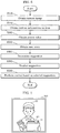
- FIG. 6 is a flow chart illustrating processing of the information processing system according to Embodiment 1.
- FIG. 7 is an example of camera image 301 according to Embodiment 1.
- camera image 301 includes delivery person 50 and item 40.
- Camera image 301 also includes sheet 41 on which identification information identifying content information of item 40 is provided.
- the identification information is provided on sheet 41 in the form of a bar code and/or a character string.
- Processor 101 of information processing server 100 obtains the content information of item 40. Specifically, processor 101 first obtains the identification information from camera image 301. Then, processor 101 obtains the content information of item 40 based on the obtained identification information, by referring to second data 802a. For example, processor 101 obtains 000001 as the identification information by reading the bar code provided on sheet 41 of camera image 301. Then, by referring to second data 802a in FIG. 4 , processor 101 obtains, as the content information of item 40, image information .../image01.jpg and urgent flag 1 which are associated with 000001.
- processor 101 does not necessarily need to obtain the content information of item 40 based on the identification information.
- processor 101 may obtain the content information of item 40 based on the date and time of obtainment of the image, by referring to second data 802a. For example, when camera image 301 was captured at 11:55 on October 30, 2018, processor 101 may obtain, as the content information of item 40, image information .../image01.jpg and urgent flag 1 which are associated with the scheduled delivery date and time 2018/10/30 12:00 which is closest to the actual capturing date and time.
- Processor 101 of information processing server 100 obtains a sensor value that is an output value of sensor 700.
- sensor 700 is an image sensor, for example, processor 101 obtains image data as the sensor value.
- sensor 700 is an ON/OFF sensor, for example, processor 101 obtains an ON/OFF signal as the sensor value.
- Processor 101 of information processing server 100 obtains a user state using sensor 700. Specifically, processor 101 obtains a user state based on a sensor value obtained by sensor 700, for example. More specifically, processor 101 obtains a user state based on a sensor value by referring to first data 801a. At this time, processor 101 may identify the user based on the sensor value, and obtain a user state based on the identified user and the sensor value by referring to first data 801a.
- processor 101 recognizes the user based on image data.
- the method for user recognition is not particularly limited, and a conventional technique may be used.
- processor 101 identifies user 20 as USER 1.
- processor 101 obtains, by referring to first data 801a in FIG. 3 , a user state indicating that user 20 is currently cooking using cooker 600.
- processor 101 obtains a user state indicating that user 20 is currently cooking using cooker 600.
- processor 101 obtains an OFF signal
- processor 101 obtains a user state indicating that user 20 is not cooking using cooker 600.
- Processor 101 of information processing server 100 determines at least one suggestion. Specifically, processor 101 obtains at least one suggestion associated with the user state and the content information of item 40. For example, processor 101 obtains, by referring to third data 803a, at least one suggestion associated with the obtained user state and content information of item 40.
- processor 101 obtains, by referring to third data 803a in FIG. 5 , a first suggestion to turn off cooker 600 and a second suggestion to unlock electronic lock 400 on entrance door 30 of the building.
- processor 101 obtains, by referring to third data 803a in FIG. 5 , a first suggestion to request redelivery of item 40 and a second suggestion to receive item 40.
- processor 101 obtains, by referring to third data 803a in FIG. 5 , a first suggestion to unlock electronic lock 400 on entrance door 30 of the building. In other words, in this case, processor 101 obtains a single suggestion.
- processor 101 obtains, by referring to third data 803a in FIG. 5 , a first suggestion to receive item 40 and a second suggestion to request redelivery of item 40.
- Processor 101 of information processing server 100 causes display terminal 200 to display at least one suggestion determined. For example, processor 101 transmits screen data including at least one suggestion to display terminal 200.
- processor 101 transmits screen data including at least one suggestion to display terminal 200.
- specific examples of a screen displayed by display terminal 200 will be described with reference to FIG. 8 to FIG. 12 .
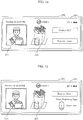
- FIG. 8 illustrates an example of a first screen according to Embodiment 1.
- the first screen is displayed when the user state indicates that the user is currently cooking and the urgent information indicates that the delivery is urgent.
- display 204 displays, in sequence from the left to the right, camera image 211, image 212 of item 40, first suggestion 213 to turn off cooker 600, and second suggestion 214 to unlock electronic lock 400 on entrance door 30.
- device control corresponding to the selected suggestion is performed. That is to say, the screen of display 204 is segmented.
- the screen includes a region for displaying a camera image, a region for displaying the content of an item, and a region for displaying at least one suggestion.
- Display 204 also displays, at the top, a current date and time, a login user, and various states. The display of such information is a mere example, and is not limited to this example.
- Camera image 211, image 212 of item 40, and first and second suggestions 213 and 214 are respectively displayed in three display regions arranged horizontally on display 204.
- the three display regions are identical in shape and size.
- Each of the three display regions is a square region occupying about one third of the display area of display 204.
- being identical encompasses being substantially identical as well as being strictly identical. In other words, being identical means being approximately identical.
- a square encompasses a precise square and shapes which can be considered substantially identical to a precise square.
- the screen may include three display regions only. In a more limited example, the screen of display 200 may only include three display regions that are identical in size and shape.
- First suggestion 213 and second suggestion 214 are arranged next to each other vertically.
- first suggestion 213 is displayed with higher priority by being displayed above second suggestion 214.
- the method for display with priority is not limited to the vertical arrangement.
- first suggestion 213 may be displayed with higher priority by being displayed in a different size or color.
- Camera image 211, image 212 of item 40, and first and second suggestions 213 and 214 may be displayed on display 204 simultaneously, for example. In other words, the three pieces of information may simultaneously start being displayed.
- image 212 of item 40 and first and second suggestions 213 and 214 may be displayed with camera image 211. This way, image 212 of item 40 and first and second suggestions 213 and 214 are displayed after the user recognizes camera image 211, thus assisting the user to grasp the current situation in sequence. For example, when the user sees camera image 211 and recognizes that a delivery item has arrived, the user considers what to do next.
- image 212 of item 40 and first and second suggestions 213 and 214 By displaying image 212 of item 40 and first and second suggestions 213 and 214 at this timing, it is possible to provide the user with information appropriate to the user's situation. For example, since the user in, for example, a residence or an apartment building uses the system on a daily basis and becomes familiar with the information displayed on display 204, camera image 211, image 212 of item 40, and first and second suggestions 213 and 214 may be displayed simultaneously if the user has used the system for a certain period or longer. Examples of the certain period include one week, one month, and three months. In the case of an office building, a commercial building, or a hotel, for example, the user may not use the system on a daily basis, and thus may be unfamiliar with the information displayed on display 204.
- camera image 211 may be displayed first, and image 212 of item 40 and first and second suggestions 213 and 214 may be displayed next, so that even the unfamiliar user can easily understand the information.
- image 212 of item 40 and first and second suggestions 213 and 214 may be separately displayed sequentially.
- Camera image 211 is included to allow user 20 to recognize arrival of delivery person 50, when delivery person 50 arrives at entrance door 30 of the building.
- Image 212 of item 40 is included to show the content of item 40 delivered by delivery person 50. This allows user 20 to recognize item 40 that is being delivered by delivery person 50.
- the first screen includes first suggestion 213 and second suggestion 214 to provide guidance on the next action of user 20 in response to camera image 211 and image 212 of item 40. Because user 20 is highly likely to receive item 40, first suggestion 213 and second suggestion 214 are displayed as the next action of user 20 determined based on image 212 of item 40. That is to say, first suggestion 213 and second suggestion 214 are included based on the presumption that user 20 is highly likely to turn off cooker 600 and/or unlock electronic lock 400 to receive urgent item 40.
- the first screen includes camera image 301 and image 212 of item 40 to allow user 20 to easily check item 40 delivered to user 20. Further, the first screen includes first suggestion 213 and second suggestion 214 as the next action of user 20 determined based on camera image 301 and image 212 of item 40. By seeing the first screen, user 20 can check, all at once, the arrival of delivery person 50 delivering item 40, the content of item 40, and the next action, and can then take an action.
- FIG. 9 illustrates an example of a second screen according to Embodiment 1.
- the second screen is displayed when the user state indicates that the user is currently cooking and the urgent information indicates that the delivery is non-urgent.
- display 204 displays, in sequence from the left to the right, camera image 211, image 212 of item 40, first suggestion 215 to request redelivery of item 40, and second suggestion 216 to receive item 40.
- first suggestion 215 a third screen, which will be described later, is displayed on display 204, for example.
- second suggestion 216 the first screen in FIG. 8 is displayed, for example.
- user 20 can check, all at once, the arrival of delivery person 50 delivering item 40, the content of item 40, and the next action, and can then take an action.
- FIG. 10 illustrates an example of the third screen according to Embodiment 1.
- the third screen is displayed after the user has selected the suggestion to request redelivery of item 40.
- display 204 displays, in sequence from the left to the right, camera image 211, image 212 of item 40, and graphical user interface (GUI) 217 via which user 20 can select a redelivery time and transmit a redelivery request to information terminal 500 of delivery person 50.
- GUI graphical user interface
- User 20 can select a redelivery time by operating GUI 217. For example, by pressing GUI 217, it is possible to transmit a redelivery request to information terminal 500, requesting delivery person 50 to redeliver item 40 after the selected number of hours. That is to say, a request for redelivery of item 40 is transmitted to information terminal 500 when a selection of the suggestion to request redelivery of item 40 is received.
- FIG. 11 illustrates an example of a fourth screen according to Embodiment 1.
- the fourth screen is displayed when the user state indicates that the user is not cooking and the urgent information indicates that the delivery is urgent.
- display 204 displays, in sequence from the left to the right, camera image 211, image 212 of item 40, and first suggestion 218 to unlock electronic lock 400 on entrance door 30.
- first suggestion 218 to unlock electronic lock 400 on entrance door 30.
- electronic lock 400 is unlocked.
- user 20 can check, all at once, the arrival of delivery person 50 delivering item 40, the content of item 40, and the next action, and can then take an action.
- FIG. 12 illustrates an example of a fifth screen according to Embodiment 1.
- the fifth screen is displayed when the user state indicates that the user is not cooking and the urgent information indicates that the delivery is non-urgent.
- display 204 displays, in sequence from the left to the right, camera image 211, image 212 of item 40, first suggestion 219 to receive item 40, and second suggestion 220 to request redelivery of item 40.
- first suggestion 219 is performed
- second suggestion 220 is performed
- the third screen in FIG. 10 is displayed, for example.
- user 20 can check, all at once, the arrival of delivery person 50 delivering item 40, the content of item 40, and the next action, and can then take an action.
- Processor 101 of information processing server 100 performs control based on the suggestion selected. For example, processor 101 transmits an unlock signal to electronic lock 400 on entrance door 30 when display terminal 200 receives a selection of the suggestion to unlock electronic lock 400 (second suggestion 214 in FIG. 8 , for example). This way, electronic lock 400 is unlocked. For example, an OFF signal is transmitted to cooker 600 when display terminal 200 receives a selection of the suggestion to turn off cooker 600 (first suggestion 213 in FIG. 8 , for example). This way, cooker 600 becomes non-operational.
- entrance door 30 is an entrance door in a public space of, for example, an apartment building, an office building, or a commercial building
- electronic lock 400 may be unlocked after a lapse of a first period or less, following the reception of the unlock signal.
- An example of the first period is a period required for communication, or a few seconds.
- entrance door 30 is an entrance door leading directly to a private space such as a residence, an office, or a shop
- delivery person 50 can enter the private space before the user arrives at entrance door 30, and thus, the user may not feel safe using the system.
- electronic lock 40 on entrance door 30 to a public space electronic lock 40 on entrance door 30 to a private space may be unlocked after a lapse of a second period which is longer than the first period, following the reception of the unlock signal.
- An example of the second period is an average period required for the user to come to entrance door 30, or 30 seconds.
- the second period may be user-settable. For example, in the case of a residence, the second period may be set to a time period corresponding to the distance from the user to the kitchen.
- information processing server 100 can: (a) obtain, using sensor 700, a user state indicating whether user 20 is currently cooking using cooker 600, when an image of delivery person 50 delivering item 40 to a building in which user 20 is present is captured by camera 300 provided at entrance door 30 of the building; (b) obtain content information of item 40; (c) obtain at least one suggestion associated with the user state and the content information of item 40; and (d) cause display terminal 200 provided in the building to display the image of delivery person 50, the content information of item 40, and the at least one suggestion.
- the content information of item 40 includes urgent information indicating whether delivery of item 40 is urgent, and in (c), when the user state indicates that user 20 is currently cooking and the urgent information indicates that the delivery is urgent, information processing server 100 can obtain, as the at least one suggestion, a suggestion to turn off cooker 600 and a suggestion to unlock electronic lock 400 on entrance door 30 of the building.
- information processing server 100 can obtain, as the at least one suggestion, a suggestion to request redelivery of item 40 and a suggestion to receive item 40.
- information processing server 100 can obtain, as the at least one suggestion, a suggestion to unlock electronic lock 400 on entrance door 30 of the building.
- information processing server 100 can obtain, as the at least one suggestion, a suggestion to receive item 40 and a suggestion to request redelivery of item 40.
- the content information of item 40 includes the urgent information
- the content information of item 40 is not limited to this.
- the content information of item 40 may include the type of item 40.
- the type of item 40 is fresh food, frozen food, or the like. In such a case, at least one suggestion is obtained based on the user state and the type of item 40.
- the content information of item 40 in the present embodiment includes an image of item 40; however, a product name of item 40 may be included instead of an image of item 40.
- the content information of item 40 may include both an image of item 40 and a product name of item 40.
- the screens and data illustrated in the present embodiment are mere examples, and the present disclosure is not limited to these examples.
- the display regions in which the three pieces of information are displayed need not be identical in size and shape.
- the combinations of (i) a user state and an urgent flag and (ii) a first suggestion and a second suggestion, illustrated in FIG. 5 are a mere example, and the present disclosure is not limited to this example.
- First suggestions and second suggestions different from those in FIG. 5 may be associated with user states and urgent flags.
- Unlock may be used as the first suggestion and Receive Later as the second suggestion.
- Cooker OFF may be used as the first suggestion and Receive Later as the second suggestion.
- Receive Now may be used as the first suggestion and Select Redelivery Time as the second suggestion.
- Unlock & Cooker OFF may be used as the first suggestion and Receive Later as the second suggestion.
- the user states and the values of the urgent flag that lead to the screen examples in FIG. 8 to FIG. 16 are not particularly limited, and any user state and any value of the urgent flag may lead to the screen examples in FIG. 8 to FIG. 16 .
- first data 801a, second data 802a, and third data 803a are referred to, however; the present disclosure is not limited to this.
- first data 801a need not be referred to. In such a case, whether or not the user is currently cooking may be directly determined based on the ON/OFF signal of cooker 600, for example.
- second data 802a need not be referred to. In such a case, the content information of item 40 may be directly obtained from a camera image, for example.
- third data 803a need not be referred to. In such a case, third data 803a may be hard coded.
- Steps S201 and S202 may be performed before Steps S101 and 102.
- a selection screen may be displayed for the user to select the user's preferred display mode for display 200 in Step S302, out of a display mode in which plural pieces of information are sequentially displayed in the display regions and a display mode in which plural pieces of information are simultaneously displayed in the display regions.
- the display mode for Step S302 which is to be applied next time the service is provided is determined based on the display mode selected by the user.
- the user may be given a choice among the first to fifth screens illustrated in FIG. 8 to FIG. 12 .
- the initial setting may be the first screen
- display 200 may display, to the user, the first to fifth screens and a message prompting the user to select a screen which the user wishes to be displayed from next time onward. From next time onward, suggestions are displayed to the user based on the screen selected by the user. For example, the first to fifth screens are displayed in a temporal order.
- display 200 may display again the first to fifth screens and a message prompting the user to select a screen which the user wishes to be displayed from next time onward. Examples of the certain number of times include 10, 30, and 50.
- the present embodiment describes a service providing system that provides a service including provision of information on a screen to be displayed on a display terminal.
- FIG. 17A illustrates an overview of a service providing system according to Embodiment 2.
- Group 1000 may be, for example, a company, an organization, or a household of any size.
- Group 1000 includes device A and device B that are included in devices 1010, and home gateway 1020.
- Device A is, for example, cooker 600 according to Embodiment 1.
- Devices 1010 include devices connectable to the Internet (e.g., a smartphone, PC, and TV) and devices unconnectable to the Internet by themselves (e.g., an illumination and a washing machine).
- Devices 1010 may include devices that are unconnectable to the Internet by themselves but are connectable to the Internet via home gateway 1020.
- group 1000 includes users 990A of devices 1010.
- Data center operating company 1100 includes cloud server 1110.
- Cloud server 1110 is a virtual server that operates in cooperation with various devices via the Internet.
- cloud server 1110 is information processing server 100 according to Embodiment 1.
- Cloud server 1110 mainly manages large data (big data) that is hard to handle with ordinary database management tools or the like.
- Data center operating company 1100 manages data and cloud server 1110 and, for example, operates a data center for the management. Service provided by data center operating company 1100 will be specifically described later. In this case, data center operating company 1100 is not limited to companies that are only involved in data management and the operation etc. of cloud server 1110.
- Data center operating company 1100 is not limited to a single company.
- a device manufacturer and another management company are involved in data management and the operation of cloud server 1110 in a collaborative or shared manner, at least one of the device manufacturer and the management company is equivalent to data center operating company 1100 ( FIG. 17C ).
- Service provider 1200 possesses server 1210.
- server 1210 includes, for example, memory in a personal PC regardless of the size.
- the service provider may not possess server 1210.
- home gateway 1020 is not mandatory. For example, if cloud server 1110 totally manages data, home gateway 1020 is not necessary. There are also cases where devices unconnectable to the Internet by themselves are not provided, as in the case where all the home devices are connected to the Internet.
- device A or device B of group 1000 transmits information obtained in each device to cloud server 1110 of data center operating company 1100.
- Cloud server 1110 accumulates information on device A or device B ((a) of FIG. 17A ).
- the accumulated information indicates, for example, the operating condition, the operation date and time, the operation mode, and the position of each device 1010.
- the information includes but is not limited to the television viewing history, information on the recording schedule of a recorder, the operating date and time of a washing machine, the amount of laundry, the date and time of opening/closing of a refrigerator, the number of times of opening/closing of a refrigerator, and the amount of foods in a refrigerator. Any kinds of information available from all the devices can be used.
- Information may be directly provided to cloud server 1110 from devices 1010 via the Internet.
- information may be temporarily accumulated in home gateway 1020 from devices 1010 and then provided to cloud server 1110 from home gateway 1020.
- cloud server 1110 of data center operating company 1100 provides service provider 1200 with the accumulated information in constant units.
- the constant units may be units in which the data center operating company can organize and provide the accumulated information to service provider 1200 or units requested by service provider 1200.
- the units need not be constant units.
- the amount of information provided may vary depending on the circumstances.
- the information is stored in server 1210 provided in service provider 1200 ((b) in FIG. 17A ).
- service provider 1200 organizes the information suitably for user service and then provides the information to users.
- the users whom the information is provided to may be users 990A of devices 1010 or external users 990B.
- the service may be directly provided to users from the service provider, for example ((e) and (f) of FIG.
- the service may be provided to users after passing through, for example, cloud server 1110 of data center operating company 1100 again ((c) and (d) of FIG. 17A ).
- Cloud server 1110 of data center operating company 1100 may organize the information suitably for user service and then provide the information to service provider 1200.
- User 990A and user 990B may be different from each other or identical to each other.
- types of cloud service for implementing the techniques described in the embodiments are not limited to the following types:
- FIG. 18 illustrates service type 1 (company-owned data center).
- service provider 1200 obtains information from group 1000 and provides service to users.
- service provider 1200 has the function of the data center operating company.
- the service provider includes cloud server 1110 that manages big data. Thus, data center operating companies are not present.
- service provider 1200 operates and manages data center 903 (cloud server 1110). Moreover, service provider 1200 manages OS 902 and application 901. Service provider 1200 provides service 904 by using OS 902 and application 901 that are managed by service provider 1200.
- FIG. 19 illustrates service type 2 (IaaS-based).
- IaaS stands for Infrastructure as a Service, which is a cloud service provision model for providing, as service via the Internet, an infrastructure for constructing and operating a computer system.
- data center operating company 1100 operates and manages data center 903 (cloud server 1110).
- service provider 1200 manages OS 902 and application 901.
- Service provider 1200 provides service 904 by using OS 902 and application 901 that are managed by service provider 1200.
- FIG. 20 illustrates service type 3 (PaaS-based).
- PaaS stands for Platform as a Service, which is a cloud service provision model for providing, as service via the Internet, a platform for constructing and operating software.
- data center operating company 1100 manages OS 902 and operates and manages data center 903 (cloud server 1110).
- service provider 1200 manages application 901.
- Service provider 1200 provides service 904 by using OS 902 managed by the data center operating company and application 901 managed by service provider 1200.
- FIG. 21 illustrates service type 4 (SaaS-based).
- SaaS stands for Software as a Service.
- SaaS is a cloud service provision model that enables a company/individual (user) who does not have a data center (cloud server) to use an application provided by a platform provider having a data server (cloud server) via a network such as the Internet.
- data center operating company 1100 manages application 901, manages OS 902, and operates and manages data center 903 (cloud server 1110).
- Service provider 1200 provides service 904 by using OS 902 and application 901 that are managed by data center operating company 1100.
- service is provided by service provider 1200.
- the service provider or the data center operating company may develop its own OS, application, or the database of big data etc., or outsource the development to a third party.
- an aspect of the present disclosure may be a display control method which includes, as steps, not only processing performed by such an information processing system, but also processing performed by a processor included in the information processing system.
- an aspect of the present disclosure may be a computer program which causes a computer to perform each characteristic step included in a display control method.
- an aspect of the present disclosure may be a non-transitory computer-readable recording medium having such a computer program recorded thereon.
- Such a program causes a computer to (a) obtain, using a sensor, a user state indicating whether a user is currently cooking using a cooker, when an image of a delivery person delivering an item to a building in which the user is present is captured by a camera provided at an entrance door of the building; (b) obtain content information of the item; (c) obtain at least one suggestion associated with the user state and the content information of the item; and (d) cause a display terminal provided in the building to display the image of the delivery person, the content information of the item, and the at least one suggestion.
- part or all of the units and devices, or part or all of the functional blocks in the block diagram illustrated in FIG. 2 may be implemented by one or more electric circuits including a semiconductor device, a semiconductor integrated circuit (IC), or a large scale integration (LSI) circuit.
- LSI or IC may be integrated in a single chip, or may be configured by combining a plurality of chips.
- functional blocks other than memory elements may be integrated in a single chip.
- the names used here are LSI and IC, but the integrated circuit may also be called a system LSI circuit, a very LSI circuit (VLSI), or an ultra LSI (ULSI) circuit depending on the degree of integration.
- a field programmable gate array (FPGA) programed after manufacturing of the LSI circuit or a reconfigurable logic device which is reconfigurable in connection or settings of circuit cells inside the LSI circuit may be used for the same purpose.
- FPGA field programmable gate array
- the functions or operations of the units, devices, or part of the devices can be performed through software processing.
- software is recorded on a non-transitory recording medium such as one or more ROMs, optical discs, or hard disk drives, and the software, when executed by a processor, causes the processor and a peripheral device to perform particular functions of the software.
- the system or device may include one or more non-transitory recording media having software recorded thereon, a processor, and a necessary hardware device, such as an interface.
- the present disclosure is applicable to an information processing system which provides a user with a suggestion of an action to take when a delivery person with a delivery item arrives at a building in which the user is present.
Landscapes
- Engineering & Computer Science (AREA)
- Signal Processing (AREA)
- General Physics & Mathematics (AREA)
- Physics & Mathematics (AREA)
- Automation & Control Theory (AREA)
- Human Computer Interaction (AREA)
- Multimedia (AREA)
- Computer Networks & Wireless Communication (AREA)
- Management, Administration, Business Operations System, And Electronic Commerce (AREA)
- Interconnected Communication Systems, Intercoms, And Interphones (AREA)
- User Interface Of Digital Computer (AREA)
- Closed-Circuit Television Systems (AREA)
- Telephonic Communication Services (AREA)
Abstract
Description
- The present disclosure relates to a display control method, an information processing server, and a display terminal for controlling display of a suggestion regarding reception of an item from a delivery person who delivers the item to a building in which a user is present.
- There is a conventional technique of displaying an image captured by a camera provided at the entrance door of a building, on a display terminal in the building. For example, Patent Literature (PTL) 1 discloses a video door phone device for stable wireless communication between an indoor master unit and an entrance slave unit. With such a video door phone device, when, for example, a delivery person arrives at the door of a building and activates an intercom, an image of the delivery person captured by the entrance slave unit is displayed on the display of the indoor master unit.
- PTL 1: Japanese Unexamined Patent Application Publication No.
2017-220795 - With the above conventional technique, however, the indoor master unit only displays the image of the delivery person, and thus, it is not possible to effectively present the user with information which assists the user in determining the next action.
- In view of this, the present disclosure provides a display control method and the related technologies capable of effectively presenting a user with information which assists the user in determining the next action when a delivery person arrives with a delivery item.
- A display control method according to an aspect of the present disclosure is a display control method performed using a system including an information processing server, and the display control method includes: (a) obtaining, by the information processing server, using a sensor, a user state indicating whether a user is currently cooking using a cooker, when an image of a delivery person delivering an item to a building in which the user is present is captured by a camera provided at an entrance door of the building; (b) obtaining, by the information processing server, content information of the item; (c) obtaining, by the information processing server, at least one suggestion associated with the user state and the content information of the item; and (d) causing, by the information processing server, a display terminal provided in the building to display the image of the delivery person, the content information of the item, and the at least one suggestion.
- Note that these general or specific aspects may be implemented using a system, a device, an integrated circuit, a computer program, or a computer-readable recording medium such as a CD-ROM, or any combination of systems, devices, integrated circuits, computer programs, or recording media.
- A display control method according to an aspect of the present disclosure is capable of effectively presenting a user with information which assists the user in determining the next action when a delivery person arrives with a delivery item.
-
-
FIG. 1 is an external view of an information processing system and peripheral devices according toEmbodiment 1. -
FIG. 2 is a block diagram illustrating a functional configuration of the information processing system according toEmbodiment 1. -
FIG. 3 illustrates an example of first data according toEmbodiment 1. -
FIG. 4 illustrates an example of second data according to Embodiment 1. -
FIG. 5 illustrates an example of third data according to Embodiment 1. -
FIG. 6 is a flow chart illustrating processing of the information processing system according toEmbodiment 1. -
FIG. 7 illustrates an example of a camera image according to Embodiment 1. -
FIG. 8 illustrates an example of a first screen according toEmbodiment 1. -
FIG. 9 illustrates an example of a second screen according toEmbodiment 1. -
FIG. 10 illustrates an example of a third screen according toEmbodiment 1. -
FIG. 11 illustrates an example of a fourth screen according toEmbodiment 1. -
FIG. 12 illustrates an example of a fifth screen according to Embodiment 1. -
FIG. 13 illustrates an example of another screen according toEmbodiment 1. -
FIG. 14 illustrates an example of another screen according toEmbodiment 1. -
FIG. 15 illustrates an example of another screen according toEmbodiment 1. -
FIG. 16 illustrates an example of another screen according toEmbodiment 1. -
FIG. 17A illustrates an overview of a service providing system according toEmbodiment 2. -
FIG. 17B illustrates an example of a data center operating company according to Embodiment 2. -
FIG. 17C illustrates an example of a data center operating company according to Embodiment 2. -
FIG. 18 illustrates service type 1 (company-owned data center) according to Embodiment 2. -
FIG. 19 illustrates service type 2 (IaaS-based) according to Embodiment 2. -
FIG. 20 illustrates service type 3 (PaaS-based) according to Embodiment 2. -
FIG. 21 illustrates service type 4 (SaaS-based) according to Embodiment 2. - Hereinafter, embodiments will be described in detail with reference to the accompanied drawings.
- Note that the following embodiments each illustrate a general or specific example. The numerical values, shapes, materials, constituent elements, the arrangement and connection of the constituent elements, steps, the processing order of the steps, etc. illustrated in the following exemplary embodiments are mere examples, and are therefore not intended to limit the scope of the claims. Among the constituent elements in the following embodiments, those not recited in any one of the independent claims representing the most generic concepts will be described as optional constituent elements. Note that the drawings are represented schematically and are not necessarily precise illustrations. Throughout the drawings, constituent elements that are essentially the same share like reference signs, and overlapping descriptions thereof are omitted or simplified.
- The following describes the knowledge forming the basis of an information processing system and method according to the present disclosure. The inventor has considered the actions that a user would take when a delivery person comes. When a delivery person comes, the user takes different actions depending on the user's situation. Meanwhile, the user is required to take a prompt action in response to the delivery person. In view of this, an information processing system and method according to the present disclosure provide the user with information about the delivery to make it easier for the user to determine the action that the user wants to take. Additionally, an information processing system and method according to the present disclosure simplify the user's action by providing the user with a suggestion to expedite the user's action, and controlling devices according to the user's response to the suggestion displayed. That is to say, the inventor has conceived an information processing system and method which display, on one screen, both information about the delivery and a suggestion for expediting the user's action, to facilitate both the user's understanding of the situation and the user's action.
- First, configurations of an information processing system and peripheral devices according to
Embodiment 1 will be described with reference toFIG. 1 to FIG. 5 .FIG. 1 is an external view of an information processing system and peripheral devices according toEmbodiment 1.FIG. 2 is a block diagram illustrating a functional configuration of the information processing system according toEmbodiment 1. -
Information processing system 10 includesinformation processing server 100 and one or more display terminals includingdisplay terminal 200.Information processing server 100 and one or more display terminals are communicably connected to one another. Hereinafter,display terminal 200 will be described as a representative of the one or more display terminals, and description of the rest of the display terminals will be omitted. -
Information processing system 10 is communicably connected tocamera 300,electronic lock 400,information terminal 500,cooker 600,sensor 700,first database 801,second database 802, andthird database 803. -
Information processing server 100 is, for example, a cloud server, and causesdisplay terminal 200 to display at least one suggestion based on a user state. -
Display terminal 200 includes a display, and displays, on the display, at least one suggestion received frominformation processing server 100. In the present embodiment,display terminal 200 is provided on a wall surface in a building. Alternatively,display terminal 200 may be a mobile terminal. -
Camera 300 is provided atentrance door 30 of the building. InFIG. 1 ,camera 300 is built into a door phone. For example,camera 300 captures an image ofdelivery person 50 who deliversitem 40 to the building in whichuser 20 is present. The building includes, for example, a residence, an apartment building, an office building having a plurality of offices, a commercial building having a plurality of shops, and a hotel having a plurality of rooms.Entrance door 30 of an apartment building may be an entrance door of each residence, or may be an entrance door of the apartment building.Entrance door 30 of an office building may be an entrance door of each office, or may be an entrance door of the office building. Likewise,entrance door 30 of a commercial building may be an entrance door of each shop, or may be an entrance door of the commercial building. -
Electronic lock 400 is a lock capable of remote control on the opening and closing ofentrance door 30 of the building.Electronic lock 400 is also referred to as an electronic key.Electronic lock 400 controls the opening and closing ofentrance door 30 based on a lock/unlock signal frominformation processing system 10. -
Information terminal 500 is a terminal usable bydelivery person 50.Information terminal 500 is a handy terminal carried bydelivery person 50, for example.Information terminal 500, for example, receives a request for redelivery ofitem 40 frominformation processing system 10.Information terminal 500 may be provided atentrance door 30, for example. -
Cooker 600 is a device used whenuser 20 cooks.Cooker 600 is, for example, a microwave oven, a cooking stove, or the like.Cooker 600 can control power ON and OFF based on a signal frominformation processing system 10. -
Sensor 700 transmits to information processing system 10 a sensor value used for obtaining a user state indicating whetheruser 20 is currently cooking usingcooker 600. Specifically,sensor 700 is, for example, an image sensor which is provided in the building and captures an image of the inside of the building.Sensor 700 may be, for example, an ON/OFF sensor which detects power ON and OFF ofcooker 600. -
First database 801 is a storage device storingfirst data 801a which associates sensor values and user states for each of a plurality of users. Specifically,first database 801 is, for example, a database server which includes a processor, memory, and a hard disk drive. - Here,
first data 801a will be described using a specific example.FIG. 3 illustrates an example offirst data 801a according toEmbodiment 1. - In
FIG. 3 ,first data 801a includes user information, sensor value, and user state. User information is information that identifies users. Sensor value represents an image pattern, for example. User state indicates whether a user is currently cooking. According tofirst data 801a inFIG. 3 , the user state is determined to be cooking whenPattern 1 is included in an image of the user identified asUSER 1. -
Second database 802 is a storage device storingsecond data 802a which associates (i) a plurality of pieces of identification information or a plurality of scheduled delivery dates and times and (ii) pieces of content information of a plurality of items. Specifically,second database 802 is, for example, a database server which includes a processor, memory, and a hard disk drive. - Here,
second data 802a will be described using a specific example.FIG. 4 illustrates an example ofsecond data 802a according toEmbodiment 1. - In
FIG. 4 ,second data 802a includes ID, scheduled delivery date and time, image information, and urgent flag. ID is an example of identification information for identifying content information. Scheduled delivery date and time indicates a date and time of scheduled delivery of an item. - Image information is identifier information which identifies an image of an item (for example, a uniform resource identifier (URI)). Urgent flag is an example of urgent information indicating whether the delivery of the item is urgent. For example, the urgent flag is set by the user when the user purchases an item via a website. Here,
urgent flag 1 indicates that the delivery is urgent, whereasurgent flag 0 indicates that the delivery is non-urgent. The image information and the urgent flag correspond to the content information of the item. - It can be seen from
second data 802a inFIG. 4 that, for example, the image of an item identified by 000001 is .../image01.jpg, and that the delivery of this item is urgent. It can also be seen that the image of an item scheduled to be delivered on 2018/10/30 at 12:00 is .../image01.jpg, and that the delivery of this item is urgent. -
Third database 803 is a storage device storingthird data 803a which associates (i) a plurality of combinations of a user state and content information of an item and (ii) a plurality of suggestion sets each including at least one suggestion. Specifically,third database 803 is, for example, a database server which includes a processor, memory, and a hard disk drive. - Here,
third data 803a will be described using a specific example.FIG. 5 illustrates an example ofthird data 803a according toEmbodiment 1. -
Third data 803a inFIG. 5 includes user state, urgent flag, first suggestion, and second suggestion. User state indicates whether the user is currently cooking. As inFIG. 4 , urgent flag is an example of urgent information indicating whether the delivery of the item is urgent. According tothird data 803a inFIG. 5 , when, for example, the user state is Cooking and the urgent information indicates Yes, the first suggestion of Cooker OFF and the second suggestion of Unlock are obtained. - Next, a configuration of
information processing server 100 will be described. As illustrated inFIG. 2 ,information processing server 100 includesprocessor 101,memory 102, andcommunication unit 103. -
Processor 101 is an electric circuit connected tomemory 102. When an image ofdelivery person 50 deliveringitem 40 to the building in whichuser 20 is present is captured bycamera 300 provided atentrance door 30 of the building,processor 101 obtains, usingsensor 700, a user state indicating whetheruser 20 is currently cooking usingcooker 600.Processor 101 further obtains content information ofitem 40.Processor 101 then obtains at least one suggestion associated with the user state, and causesdisplay terminal 200 to display the image ofdelivery person 50, the content information ofitem 40, and at least one suggestion. The details of the processing will be described later using a flow chart etc. -
Memory 102 is, for example, a semiconductor memory and/or a hard disk drive.Memory 102 can store a software program or an instruction. When the software program or the instruction stored inmemory 102 is executed,processor 101 can perform the processing described above. -
Communication unit 103 is a network adapter for performing one or both of wired communication and wireless communication withdisplay terminal 200,camera 300,electronic lock 400,information terminal 500,cooker 600,sensor 700,first database 801,second database 802, andthird database 803 via a communication network. The communication network may be, for example, the Internet, a wide area network (WAN), a local area network (LAN), or any combination of these. Wireless communication may use wireless LAN, Bluetooth (registered trademark), ZigBee (registered trademark), or any combination of these. - Next, a configuration of
display terminal 200 will be described. As illustrated inFIG. 2 ,display terminal 200 includesprocessor 201,memory 202,communication unit 203,display 204, andinput unit 205. -
Processor 201 is an electric circuit connected tomemory 202.Processor 201 displays, ondisplay 204, an image ofdelivery person 50, content information ofitem 40, and at least one suggestion which are received frominformation processing server 100. -
Memory 202 is, for example, a semiconductor memory and/or a hard disk drive.Memory 202 can store a software program or an instruction. When the software program or the instruction stored inmemory 202 is executed,processor 201 performs various processing. -
Communication unit 203 is a network adapter for performing one or both of wired communication and wireless communication withinformation processing server 100 via a communication network. -
Display 204 displays the image ofdelivery person 50, the content information ofitem 40, and at least one suggestion which are received frominformation processing server 100. For example,display 204 is a liquid crystal display or an organic EL display. -
Input unit 205 is an input device used for receiving user input. For example,input unit 205 is a touch panel (that is, a touch screen) provided integrally withdisplay 204.Input unit 205 may be, for example, a mechanical button, a mouse, a keyboard, or any combination of these and a touch panel. - Next, processing of
information processing system 10 configured as described above will be described with reference toFIG. 6 to FIG. 12 .FIG. 6 is a flow chart illustrating processing of the information processing system according toEmbodiment 1. -
Processor 101 ofinformation processing server 100 obtains an image ofdelivery person 50 from camera 300 (hereinafter also referred to as a camera image).FIG. 7 is an example ofcamera image 301 according toEmbodiment 1. InFIG. 7 ,camera image 301 includesdelivery person 50 anditem 40.Camera image 301 also includessheet 41 on which identification information identifying content information ofitem 40 is provided. For example, the identification information is provided onsheet 41 in the form of a bar code and/or a character string. -
Processor 101 ofinformation processing server 100 obtains the content information ofitem 40. Specifically,processor 101 first obtains the identification information fromcamera image 301. Then,processor 101 obtains the content information ofitem 40 based on the obtained identification information, by referring tosecond data 802a. For example,processor 101 obtains 000001 as the identification information by reading the bar code provided onsheet 41 ofcamera image 301. Then, by referring tosecond data 802a inFIG. 4 ,processor 101 obtains, as the content information ofitem 40, image information .../image01.jpg andurgent flag 1 which are associated with 000001. - Note that
processor 101 does not necessarily need to obtain the content information ofitem 40 based on the identification information. For example,processor 101 may obtain the content information ofitem 40 based on the date and time of obtainment of the image, by referring tosecond data 802a. For example, whencamera image 301 was captured at 11:55 on October 30, 2018,processor 101 may obtain, as the content information ofitem 40, image information .../image01.jpg andurgent flag 1 which are associated with the scheduled delivery date and time 2018/10/30 12:00 which is closest to the actual capturing date and time. -
Processor 101 ofinformation processing server 100 obtains a sensor value that is an output value ofsensor 700. Whensensor 700 is an image sensor, for example,processor 101 obtains image data as the sensor value. Whensensor 700 is an ON/OFF sensor, for example,processor 101 obtains an ON/OFF signal as the sensor value. -
Processor 101 ofinformation processing server 100 obtains a userstate using sensor 700. Specifically,processor 101 obtains a user state based on a sensor value obtained bysensor 700, for example. More specifically,processor 101 obtains a user state based on a sensor value by referring tofirst data 801a. At this time,processor 101 may identify the user based on the sensor value, and obtain a user state based on the identified user and the sensor value by referring tofirst data 801a. - For example, when
sensor 700 is an image sensor,processor 101 recognizes the user based on image data. The method for user recognition is not particularly limited, and a conventional technique may be used. For example,processor 101 identifiesuser 20 asUSER 1. Here, when the image data includesPattern 1,processor 101 obtains, by referring tofirst data 801a inFIG. 3 , a user state indicating thatuser 20 is currently cooking usingcooker 600. - When, for example,
sensor 700 is an ON/OFF sensor andprocessor 101 obtains an ON signal,processor 101 obtains a user state indicating thatuser 20 is currently cooking usingcooker 600. On the other hand, whenprocessor 101 obtains an OFF signal,processor 101 obtains a user state indicating thatuser 20 is not cooking usingcooker 600. -
Processor 101 ofinformation processing server 100 determines at least one suggestion. Specifically,processor 101 obtains at least one suggestion associated with the user state and the content information ofitem 40. For example,processor 101 obtains, by referring tothird data 803a, at least one suggestion associated with the obtained user state and content information ofitem 40. - For example, when the user state indicates that the user is currently cooking, and the urgent information included in the content information of
item 40 indicates that the delivery is urgent,processor 101 obtains, by referring tothird data 803a inFIG. 5 , a first suggestion to turn offcooker 600 and a second suggestion to unlockelectronic lock 400 onentrance door 30 of the building. For example, when the user state indicates that the user is currently cooking, and the urgent information indicates that the delivery is non-urgent,processor 101 obtains, by referring tothird data 803a inFIG. 5 , a first suggestion to request redelivery ofitem 40 and a second suggestion to receiveitem 40. For example, when the user state indicates that the user is not cooking, and the urgent information indicates that the delivery is urgent,processor 101 obtains, by referring tothird data 803a inFIG. 5 , a first suggestion to unlockelectronic lock 400 onentrance door 30 of the building. In other words, in this case,processor 101 obtains a single suggestion. For example, when the user state indicates that the user is not cooking, and the urgent information indicates that the delivery is urgent,processor 101 obtains, by referring tothird data 803a inFIG. 5 , a first suggestion to receiveitem 40 and a second suggestion to request redelivery ofitem 40. -
Processor 101 ofinformation processing server 100 causes display terminal 200 to display at least one suggestion determined. For example,processor 101 transmits screen data including at least one suggestion to display terminal 200. Here, specific examples of a screen displayed bydisplay terminal 200 will be described with reference toFIG. 8 to FIG. 12 . -
FIG. 8 illustrates an example of a first screen according toEmbodiment 1. The first screen is displayed when the user state indicates that the user is currently cooking and the urgent information indicates that the delivery is urgent. - As illustrated in
FIG. 8 ,display 204 displays, in sequence from the left to the right,camera image 211,image 212 ofitem 40,first suggestion 213 to turn offcooker 600, andsecond suggestion 214 to unlockelectronic lock 400 onentrance door 30. Here, when an operation to selectfirst suggestion 213 and/orsecond suggestion 214 is performed, device control corresponding to the selected suggestion is performed. That is to say, the screen ofdisplay 204 is segmented. The screen includes a region for displaying a camera image, a region for displaying the content of an item, and a region for displaying at least one suggestion.Display 204 also displays, at the top, a current date and time, a login user, and various states. The display of such information is a mere example, and is not limited to this example. -
Camera image 211,image 212 ofitem 40, and first andsecond suggestions display 204. Here, the three display regions are identical in shape and size. Each of the three display regions is a square region occupying about one third of the display area ofdisplay 204. Note that being identical encompasses being substantially identical as well as being strictly identical. In other words, being identical means being approximately identical. Furthermore, a square encompasses a precise square and shapes which can be considered substantially identical to a precise square. For example, the screen may include three display regions only. In a more limited example, the screen ofdisplay 200 may only include three display regions that are identical in size and shape. -
First suggestion 213 andsecond suggestion 214 are arranged next to each other vertically. Here,first suggestion 213 is displayed with higher priority by being displayed abovesecond suggestion 214. Note that the method for display with priority is not limited to the vertical arrangement. For example,first suggestion 213 may be displayed with higher priority by being displayed in a different size or color. -
Camera image 211,image 212 ofitem 40, and first andsecond suggestions display 204 simultaneously, for example. In other words, the three pieces of information may simultaneously start being displayed. Alternatively, for example, aftercamera image 211 is displayed,image 212 ofitem 40 and first andsecond suggestions camera image 211. This way,image 212 ofitem 40 and first andsecond suggestions camera image 211, thus assisting the user to grasp the current situation in sequence. For example, when the user seescamera image 211 and recognizes that a delivery item has arrived, the user considers what to do next. By displayingimage 212 ofitem 40 and first andsecond suggestions display 204,camera image 211,image 212 ofitem 40, and first andsecond suggestions display 204. In the case of an office building, a commercial building, or a hotel, for example,camera image 211 may be displayed first, andimage 212 ofitem 40 and first andsecond suggestions image 212 ofitem 40 and first andsecond suggestions camera image 211,image 212 ofitem 40, and first andsecond suggestions - The following describes the meaning of
camera image 211,image 212 ofitem 40, and first andsecond suggestions Camera image 211 is included to allowuser 20 to recognize arrival ofdelivery person 50, whendelivery person 50 arrives atentrance door 30 of the building.Image 212 ofitem 40 is included to show the content ofitem 40 delivered bydelivery person 50. This allowsuser 20 to recognizeitem 40 that is being delivered bydelivery person 50. - The first screen includes
first suggestion 213 andsecond suggestion 214 to provide guidance on the next action ofuser 20 in response tocamera image 211 andimage 212 ofitem 40. Becauseuser 20 is highly likely to receiveitem 40,first suggestion 213 andsecond suggestion 214 are displayed as the next action ofuser 20 determined based onimage 212 ofitem 40. That is to say,first suggestion 213 andsecond suggestion 214 are included based on the presumption thatuser 20 is highly likely to turn offcooker 600 and/or unlockelectronic lock 400 to receiveurgent item 40. - In other words, the first screen includes
camera image 301 andimage 212 ofitem 40 to allowuser 20 to easily checkitem 40 delivered touser 20. Further, the first screen includesfirst suggestion 213 andsecond suggestion 214 as the next action ofuser 20 determined based oncamera image 301 andimage 212 ofitem 40. By seeing the first screen,user 20 can check, all at once, the arrival ofdelivery person 50 deliveringitem 40, the content ofitem 40, and the next action, and can then take an action. -
FIG. 9 illustrates an example of a second screen according toEmbodiment 1. The second screen is displayed when the user state indicates that the user is currently cooking and the urgent information indicates that the delivery is non-urgent. - As illustrated in
FIG. 9 ,display 204 displays, in sequence from the left to the right,camera image 211,image 212 ofitem 40,first suggestion 215 to request redelivery ofitem 40, andsecond suggestion 216 to receiveitem 40. Here, when an operation to selectfirst suggestion 215 is performed, a third screen, which will be described later, is displayed ondisplay 204, for example. On the other hand, when an operation to selectsecond suggestion 216 is performed, the first screen inFIG. 8 is displayed, for example. - By seeing the second screen,
user 20 can check, all at once, the arrival ofdelivery person 50 deliveringitem 40, the content ofitem 40, and the next action, and can then take an action. -
FIG. 10 illustrates an example of the third screen according toEmbodiment 1. The third screen is displayed after the user has selected the suggestion to request redelivery ofitem 40. - As illustrated in
FIG. 10 ,display 204 displays, in sequence from the left to the right,camera image 211,image 212 ofitem 40, and graphical user interface (GUI) 217 via whichuser 20 can select a redelivery time and transmit a redelivery request toinformation terminal 500 ofdelivery person 50.User 20 can select a redelivery time by operatingGUI 217. For example, by pressingGUI 217, it is possible to transmit a redelivery request toinformation terminal 500, requestingdelivery person 50 to redeliveritem 40 after the selected number of hours. That is to say, a request for redelivery ofitem 40 is transmitted toinformation terminal 500 when a selection of the suggestion to request redelivery ofitem 40 is received. -
FIG. 11 illustrates an example of a fourth screen according toEmbodiment 1. The fourth screen is displayed when the user state indicates that the user is not cooking and the urgent information indicates that the delivery is urgent. - As illustrated in
FIG. 11 ,display 204 displays, in sequence from the left to the right,camera image 211,image 212 ofitem 40, andfirst suggestion 218 to unlockelectronic lock 400 onentrance door 30. Here, when an operation to selectfirst suggestion 218 is performed,electronic lock 400 is unlocked. - By seeing the fourth screen,
user 20 can check, all at once, the arrival ofdelivery person 50 deliveringitem 40, the content ofitem 40, and the next action, and can then take an action. -
FIG. 12 illustrates an example of a fifth screen according toEmbodiment 1. The fifth screen is displayed when the user state indicates that the user is not cooking and the urgent information indicates that the delivery is non-urgent. - As illustrated in
FIG. 12 ,display 204 displays, in sequence from the left to the right,camera image 211,image 212 ofitem 40,first suggestion 219 to receiveitem 40, andsecond suggestion 220 to request redelivery ofitem 40. Here, when an operation to selectfirst suggestion 219 is performed, the fourth screen inFIG. 11 is displayed, for example. On the other hand, when an operation to selectsecond suggestion 220 is performed, the third screen inFIG. 10 is displayed, for example. - By seeing the fifth screen,
user 20 can check, all at once, the arrival ofdelivery person 50 deliveringitem 40, the content ofitem 40, and the next action, and can then take an action. -
Processor 101 ofinformation processing server 100 performs control based on the suggestion selected. For example,processor 101 transmits an unlock signal toelectronic lock 400 onentrance door 30 whendisplay terminal 200 receives a selection of the suggestion to unlock electronic lock 400 (second suggestion 214 inFIG. 8 , for example). This way,electronic lock 400 is unlocked. For example, an OFF signal is transmitted tocooker 600 whendisplay terminal 200 receives a selection of the suggestion to turn off cooker 600 (first suggestion 213 inFIG. 8 , for example). This way,cooker 600 becomes non-operational. Whenentrance door 30 is an entrance door in a public space of, for example, an apartment building, an office building, or a commercial building,electronic lock 400 may be unlocked after a lapse of a first period or less, following the reception of the unlock signal. An example of the first period is a period required for communication, or a few seconds. However, whenentrance door 30 is an entrance door leading directly to a private space such as a residence, an office, or a shop,delivery person 50 can enter the private space before the user arrives atentrance door 30, and thus, the user may not feel safe using the system. In view of this, as compared toelectronic lock 40 onentrance door 30 to a public space,electronic lock 40 onentrance door 30 to a private space may be unlocked after a lapse of a second period which is longer than the first period, following the reception of the unlock signal. An example of the second period is an average period required for the user to come toentrance door - As described above, in
information processing system 10 according to the present embodiment,information processing server 100 can: (a) obtain, usingsensor 700, a user state indicating whetheruser 20 is currently cooking usingcooker 600, when an image ofdelivery person 50 deliveringitem 40 to a building in whichuser 20 is present is captured bycamera 300 provided atentrance door 30 of the building; (b) obtain content information ofitem 40; (c) obtain at least one suggestion associated with the user state and the content information ofitem 40; and (d)cause display terminal 200 provided in the building to display the image ofdelivery person 50, the content information ofitem 40, and the at least one suggestion. - This makes it possible to display, on
display terminal 200, at least one suggestion according to the user state and the content information ofitem 40. That is to say, at least one suggestion appropriate touser 20 anditem 40 can be presented touser 20. Moreover, since the content information ofitem 40 can be displayed in addition to the image ofdelivery person 50,user 20 can determine the next action based on the content ofitem 40. Accordingly, whendelivery person 50 deliveringitem 40 arrives, it is possible to effectivelypresent user 20 with information which assistsuser 20 in determining the next action. - In
information processing system 10 according to the present embodiment, the content information ofitem 40 includes urgent information indicating whether delivery ofitem 40 is urgent, and in (c), when the user state indicates thatuser 20 is currently cooking and the urgent information indicates that the delivery is urgent,information processing server 100 can obtain, as the at least one suggestion, a suggestion to turn offcooker 600 and a suggestion to unlockelectronic lock 400 onentrance door 30 of the building. - With this, when
item 40 of an urgent delivery arrives whileuser 20 is cooking, it is possible to effectively present the user with suggestions of actions necessary for safely receivingitem 40. That is to say, it is possible to presentuser 20 with a suggestion of an action that reduces occurrence of an accident withcooker 600 while inhibiting a postponement of reception ofitem 40 of the urgent delivery, and it is possible to more effectivelypresent user 20 with information which assistsuser 20 in determining the next action. - In
information processing system 10 according to the present embodiment, in (c), when the user state indicates thatuser 20 is currently cooking and the urgent information indicates that the delivery is non-urgent,information processing server 100 can obtain, as the at least one suggestion, a suggestion to request redelivery ofitem 40 and a suggestion to receiveitem 40. - With this, when
item 40 of a non-urgent delivery arrives whileuser 20 is cooking, it is possible to present a suggestion to request redelivery ofitem 40 and a suggestion to receiveitem 40, from whichuser 20 can select the next action. That is to say, with reference to the content information ofitem 40,user 20 can determine, for eachitem 40, whether to request redelivery ofitem 40 or to receiveitem 40. In other words,information processing server 100 can more effectivelypresent user 20 with information which assistsuser 20 in determining the next action. - In
information processing system 10 according to the present embodiment, in (c), when the user state indicates thatuser 20 is not cooking and the urgent information indicates that the delivery is urgent,information processing server 100 can obtain, as the at least one suggestion, a suggestion to unlockelectronic lock 400 onentrance door 30 of the building. - With this, when
item 40 of an urgent delivery arrives whileuser 20 is not cooking, it is possible to effectively present the user with a suggestion of an action necessary for receivingitem 40. In such a case,user 20 is less likely to select, as the next action, request redelivery ofitem 40, and thus, it is possible to more effectivelypresent user 20 with information which assistsuser 20 in determining the next action. - In
information processing system 10 according to the present embodiment, in (c), when the user state indicates thatuser 20 is not cooking and the urgent information indicates that the delivery is urgent,information processing server 100 can obtain, as the at least one suggestion, a suggestion to receiveitem 40 and a suggestion to request redelivery ofitem 40. - With this, when
item 40 of an urgent delivery arrives whileuser 20 is not cooking, it is possible to present a suggestion to receiveitem 40 and a suggestion to request redelivery ofitem 40, from whichuser 20 can select the next action. That is to say, with reference to the content information ofitem 40,user 20 can determine, for eachitem 40, whether to receiveitem 40 or to request redelivery ofitem 40. In other words,information processing server 100 can more effectivelypresent user 20 with information which assistsuser 20 in determining the next action. - Note that although the content information of
item 40 according to the present embodiment includes the urgent information, the content information ofitem 40 is not limited to this. For example, the content information ofitem 40 may include the type ofitem 40. For example, the type ofitem 40 is fresh food, frozen food, or the like. In such a case, at least one suggestion is obtained based on the user state and the type ofitem 40. - Note that the content information of
item 40 in the present embodiment includes an image ofitem 40; however, a product name ofitem 40 may be included instead of an image ofitem 40. The content information ofitem 40 may include both an image ofitem 40 and a product name ofitem 40. - Note that the screens and data illustrated in the present embodiment are mere examples, and the present disclosure is not limited to these examples. For example, the display regions in which the three pieces of information are displayed need not be identical in size and shape. The combinations of (i) a user state and an urgent flag and (ii) a first suggestion and a second suggestion, illustrated in
FIG. 5 , are a mere example, and the present disclosure is not limited to this example. First suggestions and second suggestions different from those inFIG. 5 may be associated with user states and urgent flags. - For example, as illustrated in
FIG. 13 , Unlock may be used as the first suggestion and Receive Later as the second suggestion. For example, as illustrated inFIG. 14 , Cooker OFF may be used as the first suggestion and Receive Later as the second suggestion. For example, as illustrated inFIG. 15 , Receive Now may be used as the first suggestion and Select Redelivery Time as the second suggestion. For example, as illustrated inFIG. 16 , Unlock & Cooker OFF may be used as the first suggestion and Receive Later as the second suggestion. - Note that the user states and the values of the urgent flag that lead to the screen examples in
FIG. 8 to FIG. 16 are not particularly limited, and any user state and any value of the urgent flag may lead to the screen examples inFIG. 8 to FIG. 16 . - Note that in the present embodiment,
first data 801a,second data 802a, andthird data 803a are referred to, however; the present disclosure is not limited to this. For example,first data 801a need not be referred to. In such a case, whether or not the user is currently cooking may be directly determined based on the ON/OFF signal ofcooker 600, for example. Further,second data 802a need not be referred to. In such a case, the content information ofitem 40 may be directly obtained from a camera image, for example. Further,third data 803a need not be referred to. In such a case,third data 803a may be hard coded. - Note that in the present embodiment, the processing order of the flow chart in
FIG. 6 is a mere example, and the present disclosure is not limited to this example. For example, Steps S201 and S202 may be performed before Steps S101 and 102. - After the service providing system is used for a certain time period and after Step S303 is finished, a selection screen may be displayed for the user to select the user's preferred display mode for
display 200 in Step S302, out of a display mode in which plural pieces of information are sequentially displayed in the display regions and a display mode in which plural pieces of information are simultaneously displayed in the display regions. The display mode for Step S302 which is to be applied next time the service is provided is determined based on the display mode selected by the user. - Note that the user may be given a choice among the first to fifth screens illustrated in
FIG. 8 to FIG. 12 . For example, the initial setting may be the first screen, and after the processing of the flow chart illustrated inFIG. 6 is finished,display 200 may display, to the user, the first to fifth screens and a message prompting the user to select a screen which the user wishes to be displayed from next time onward. From next time onward, suggestions are displayed to the user based on the screen selected by the user. For example, the first to fifth screens are displayed in a temporal order. Further, when processing is performed a certain number of times on the screen which the user has selected,display 200 may display again the first to fifth screens and a message prompting the user to select a screen which the user wishes to be displayed from next time onward. Examples of the certain number of times include 10, 30, and 50. When the user is repeatedly prompted to select a screen for every certain number of times and the user successively selects the same screen, the user need not be prompted to select a screen after that. - Next,
Embodiment 2 will be described. The present embodiment describes a service providing system that provides a service including provision of information on a screen to be displayed on a display terminal. -
FIG. 17A illustrates an overview of a service providing system according toEmbodiment 2. -
Group 1000 may be, for example, a company, an organization, or a household of any size.Group 1000 includes device A and device B that are included indevices 1010, andhome gateway 1020. Device A is, for example,cooker 600 according toEmbodiment 1.Devices 1010 include devices connectable to the Internet (e.g., a smartphone, PC, and TV) and devices unconnectable to the Internet by themselves (e.g., an illumination and a washing machine).Devices 1010 may include devices that are unconnectable to the Internet by themselves but are connectable to the Internet viahome gateway 1020. Moreover,group 1000 includesusers 990A ofdevices 1010. - Data
center operating company 1100 includescloud server 1110.Cloud server 1110 is a virtual server that operates in cooperation with various devices via the Internet. For example,cloud server 1110 isinformation processing server 100 according toEmbodiment 1.Cloud server 1110 mainly manages large data (big data) that is hard to handle with ordinary database management tools or the like. Datacenter operating company 1100 manages data andcloud server 1110 and, for example, operates a data center for the management. Service provided by datacenter operating company 1100 will be specifically described later. In this case, datacenter operating company 1100 is not limited to companies that are only involved in data management and the operation etc. ofcloud server 1110. For example, if a device manufacturer that develops and manufactures one ofdevices 1010 also manages data andcloud server 1110, the device manufacturer is equivalent to data center operating company 1100 (FIG. 17B ). Datacenter operating company 1100 is not limited to a single company. For example, if a device manufacturer and another management company are involved in data management and the operation ofcloud server 1110 in a collaborative or shared manner, at least one of the device manufacturer and the management company is equivalent to data center operating company 1100 (FIG. 17C ). -
Service provider 1200 possessesserver 1210. In this configuration,server 1210 includes, for example, memory in a personal PC regardless of the size. The service provider may not possessserver 1210. - In this service,
home gateway 1020 is not mandatory. For example, ifcloud server 1110 totally manages data,home gateway 1020 is not necessary. There are also cases where devices unconnectable to the Internet by themselves are not provided, as in the case where all the home devices are connected to the Internet. - The flow of information in the service will be described below.
- First, device A or device B of
group 1000 transmits information obtained in each device tocloud server 1110 of datacenter operating company 1100.Cloud server 1110 accumulates information on device A or device B ((a) ofFIG. 17A ). The accumulated information indicates, for example, the operating condition, the operation date and time, the operation mode, and the position of eachdevice 1010. For example, the information includes but is not limited to the television viewing history, information on the recording schedule of a recorder, the operating date and time of a washing machine, the amount of laundry, the date and time of opening/closing of a refrigerator, the number of times of opening/closing of a refrigerator, and the amount of foods in a refrigerator. Any kinds of information available from all the devices can be used. Information may be directly provided tocloud server 1110 fromdevices 1010 via the Internet. Alternatively, information may be temporarily accumulated inhome gateway 1020 fromdevices 1010 and then provided tocloud server 1110 fromhome gateway 1020. - Next,
cloud server 1110 of datacenter operating company 1100 providesservice provider 1200 with the accumulated information in constant units. In this case, the constant units may be units in which the data center operating company can organize and provide the accumulated information toservice provider 1200 or units requested byservice provider 1200. The units need not be constant units. The amount of information provided may vary depending on the circumstances. Where necessary, the information is stored inserver 1210 provided in service provider 1200 ((b) inFIG. 17A ). Then,service provider 1200 organizes the information suitably for user service and then provides the information to users. The users whom the information is provided to may beusers 990A ofdevices 1010 orexternal users 990B. The service may be directly provided to users from the service provider, for example ((e) and (f) ofFIG. 17A ). The service may be provided to users after passing through, for example,cloud server 1110 of datacenter operating company 1100 again ((c) and (d) ofFIG. 17A ).Cloud server 1110 of datacenter operating company 1100 may organize the information suitably for user service and then provide the information toservice provider 1200. -
User 990A anduser 990B may be different from each other or identical to each other. - Techniques described in the foregoing embodiments can be implemented by, for example, the following types of cloud service. However, types of cloud service for implementing the techniques described in the embodiments are not limited to the following types:
-
FIG. 18 illustrates service type 1 (company-owned data center). In this type,service provider 1200 obtains information fromgroup 1000 and provides service to users. In this type,service provider 1200 has the function of the data center operating company. Specifically, the service provider includescloud server 1110 that manages big data. Thus, data center operating companies are not present. - In this type,
service provider 1200 operates and manages data center 903 (cloud server 1110). Moreover,service provider 1200 managesOS 902 andapplication 901.Service provider 1200 providesservice 904 by usingOS 902 andapplication 901 that are managed byservice provider 1200. -
FIG. 19 illustrates service type 2 (IaaS-based). IaaS stands for Infrastructure as a Service, which is a cloud service provision model for providing, as service via the Internet, an infrastructure for constructing and operating a computer system. - In this type, data
center operating company 1100 operates and manages data center 903 (cloud server 1110). Moreover,service provider 1200 managesOS 902 andapplication 901.Service provider 1200 providesservice 904 by usingOS 902 andapplication 901 that are managed byservice provider 1200. -
FIG. 20 illustrates service type 3 (PaaS-based). PaaS stands for Platform as a Service, which is a cloud service provision model for providing, as service via the Internet, a platform for constructing and operating software. - In this type, data
center operating company 1100 managesOS 902 and operates and manages data center 903 (cloud server 1110). Moreover,service provider 1200 managesapplication 901.Service provider 1200 providesservice 904 by usingOS 902 managed by the data center operating company andapplication 901 managed byservice provider 1200. -
FIG. 21 illustrates service type 4 (SaaS-based). SaaS stands for Software as a Service. For example, SaaS is a cloud service provision model that enables a company/individual (user) who does not have a data center (cloud server) to use an application provided by a platform provider having a data server (cloud server) via a network such as the Internet. - In this type, data
center operating company 1100 managesapplication 901, managesOS 902, and operates and manages data center 903 (cloud server 1110).Service provider 1200 providesservice 904 by usingOS 902 andapplication 901 that are managed by datacenter operating company 1100. - In all of the types, service is provided by
service provider 1200. For example, the service provider or the data center operating company may develop its own OS, application, or the database of big data etc., or outsource the development to a third party. - While the foregoing has described an information processing system according to one or more aspects of the present disclosure based on exemplary embodiments, the present disclosure is not limited to these embodiments. Various modifications to these embodiments conceivable to those skilled in the art, as well as embodiments resulting from combinations of constituent elements in different embodiments may be included within the scope of one or more aspects of the present disclosure, so long as they do not depart from the essence of the present disclosure.
- For example, an aspect of the present disclosure may be a display control method which includes, as steps, not only processing performed by such an information processing system, but also processing performed by a processor included in the information processing system. Further, an aspect of the present disclosure may be a computer program which causes a computer to perform each characteristic step included in a display control method. Furthermore, an aspect of the present disclosure may be a non-transitory computer-readable recording medium having such a computer program recorded thereon.
- Such a program causes a computer to (a) obtain, using a sensor, a user state indicating whether a user is currently cooking using a cooker, when an image of a delivery person delivering an item to a building in which the user is present is captured by a camera provided at an entrance door of the building; (b) obtain content information of the item; (c) obtain at least one suggestion associated with the user state and the content information of the item; and (d) cause a display terminal provided in the building to display the image of the delivery person, the content information of the item, and the at least one suggestion.
- In the present disclosure, part or all of the units and devices, or part or all of the functional blocks in the block diagram illustrated in
FIG. 2 may be implemented by one or more electric circuits including a semiconductor device, a semiconductor integrated circuit (IC), or a large scale integration (LSI) circuit. LSI or IC may be integrated in a single chip, or may be configured by combining a plurality of chips. For example, functional blocks other than memory elements may be integrated in a single chip. Although the names used here are LSI and IC, but the integrated circuit may also be called a system LSI circuit, a very LSI circuit (VLSI), or an ultra LSI (ULSI) circuit depending on the degree of integration. A field programmable gate array (FPGA) programed after manufacturing of the LSI circuit or a reconfigurable logic device which is reconfigurable in connection or settings of circuit cells inside the LSI circuit may be used for the same purpose. - Moreover, some or all of the functions or operations of the units, devices, or part of the devices can be performed through software processing. In such a case, software is recorded on a non-transitory recording medium such as one or more ROMs, optical discs, or hard disk drives, and the software, when executed by a processor, causes the processor and a peripheral device to perform particular functions of the software. The system or device may include one or more non-transitory recording media having software recorded thereon, a processor, and a necessary hardware device, such as an interface.
- The present disclosure is applicable to an information processing system which provides a user with a suggestion of an action to take when a delivery person with a delivery item arrives at a building in which the user is present.
-
- 10
- information processing system
- 20
- user
- 30
- entrance door
- 40
- item
- 50
- delivery person
- 100
- information processing server
- 101, 201
- processor
- 102, 202
- memory
- 103, 203
- communication unit
- 200
- display terminal
- 204
- display
- 205
- input unit
- 300
- camera
- 400
- electronic lock
- 500
- information terminal
- 600
- cooker
- 700
- sensor
- 801
- first database
- 801a
- first data
- 802
- second database
- 802a
- second data
- 803
- third database
- 803a
- third data
Claims (17)
- A display control method performed using a system including an information processing server, the display control method comprising:(a) obtaining, by the information processing server, using a sensor, a user state indicating whether a user is currently cooking using a cooker, when an image of a delivery person delivering an item to a building in which the user is present is captured by a camera provided at an entrance door of the building;(b) obtaining, by the information processing server, content information of the item;(c) obtaining, by the information processing server, at least one suggestion associated with the user state and the content information of the item; and(d) causing, by the information processing server, a display terminal provided in the building to display the image of the delivery person, the content information of the item, and the at least one suggestion.
- The display control method according to claim 1, wherein
the content information of the item includes urgent information indicating whether delivery of the item is urgent, and
in (c), when the user state indicates that the user is currently cooking and the urgent information indicates that the delivery is urgent, the information processing server obtains, as the at least one suggestion, a suggestion to turn off the cooker and a suggestion to unlock an electronic lock on the entrance door of the building. - The display control method according to claim 2, wherein
in (c), when the user state indicates that the user is currently cooking and the urgent information indicates that the delivery is non-urgent, the information processing server obtains, as the at least one suggestion, a suggestion to request redelivery of the item and a suggestion to receive the item. - The display control method according to claim 2 or claim 3, wherein in (c), when the user state indicates that the user is not cooking and the urgent information indicates that the delivery is urgent, the information processing server obtains, as the at least one suggestion, a suggestion to unlock the electronic lock on the entrance door of the building.
- The display control method according to any one of claims 2 to 4, wherein
in (c), when the user state indicates that the user is not cooking and the urgent information indicates that the delivery is urgent, the information processing server obtains, as the at least one suggestion, a suggestion to receive the item and a suggestion to request redelivery of the item. - The display control method according to any one of claims 1 to 5, wherein
the sensor is provided in the building, and
in (a), the information processing server obtains the user state based on a sensor value obtained by the sensor. - The display control method according to claim 6, wherein
in (a), the information processing server obtains the user state based on the sensor value by referring to first data associating a plurality of sensor values and a plurality of user states. - The display control method according to claim 7, wherein
the first data associates the plurality of sensor values and the plurality of user states for each of a plurality of users, and
in (a), the information processing server identifies the user based on the sensor value, and obtains the user state based on the user identified and the sensor value by referring to the first data. - The display control method according to any one of claims 1 to 8, wherein
the content information of the item includes one of a product name of the item and an image of the item. - The display control method according to any one of claims 1 to 9, wherein
the image includes identification information for identifying the content information of the item, and
in (b), the information processing server obtains the identification information from the image, and obtains the content information of the item based on the identification information by referring to second data associating a plurality of pieces of identification information and pieces of content information of a plurality of items. - The display control method according to any one of claims 1 to 10, wherein
in (b), the information processing server obtains the content information of the item based on a date and a time of obtainment of the image, by referring to second data associating scheduled delivery dates and times and pieces of content information of items. - The display control method according to claim 2 or claim 4, further comprising:
(e) transmitting, by the information processing server, an unlock signal to the electronic lock on the entrance door of the building when the display terminal receives a selection of the suggestion to unlock the electronic lock. - The display control method according to claim 3 or claim 5, further comprising:
(f) transmitting, by the information processing server, a request for redelivery of the item to an information terminal usable by the delivery person, when the display terminal receives a selection of the suggestion to request redelivery of the item. - The display control method according to claim 2, further comprising:
(g) transmitting, by the information processing server, a control signal to the cooker to turn off the cooker, when the display terminal receives a selection of the suggestion to turn off the cooker. - The display control method according to any one of claims 1 to 14, wherein
in (c), the information processing server obtains the at least one suggestion associated with the user state and the content information of the item by referring to third data associating (i) a plurality of combinations of a user state and content information of an item and (ii) a plurality of suggestion sets each including at least one suggestion. - An information processing server, comprising:a processor; andmemory, whereinusing the memory, the processor:(a) obtains, using a sensor, a user state indicating whether a user is currently cooking using a cooker, when an image of a delivery person delivering an item to a building in which the user is present is captured by a camera provided at an entrance door of the building;(b) obtains content information of the item;(c) obtains at least one suggestion associated with the user state and the content information of the item; and(d) causes a display terminal provided in the building to display the image of the delivery person, the content information of the item, and the at least one suggestion.
- A display terminal in a system, the system including an information processing server and the display terminal, the display terminal comprising:a processor; anda display, whereinthe information processing server:(a) obtains, using a sensor, a user state indicating whether a user is currently cooking using a cooker, when an image of a delivery person delivering an item to a building in which the user is present is captured by a camera provided at an entrance door of the building;(b) obtains content information of the item; and(c) obtains at least one suggestion associated with the user state and the content information of the item, andthe processor of the display terminal:(d) obtains the image of the delivery person, the content information of the item, and the at least one suggestion; and(e) displays, on the display, the image of the delivery person, the content information of the item, and the at least one suggestion.
Applications Claiming Priority (3)
| Application Number | Priority Date | Filing Date | Title |
|---|---|---|---|
| US201762611109P | 2017-12-28 | 2017-12-28 | |
| JP2018200429 | 2018-10-24 | ||
| PCT/JP2018/047763 WO2019131729A1 (en) | 2017-12-28 | 2018-12-26 | Display control method, information processing server and display terminal |
Publications (3)
| Publication Number | Publication Date |
|---|---|
| EP3734951A1 true EP3734951A1 (en) | 2020-11-04 |
| EP3734951A4 EP3734951A4 (en) | 2021-01-13 |
| EP3734951B1 EP3734951B1 (en) | 2025-07-23 |
Family
ID=67067456
Family Applications (1)
| Application Number | Title | Priority Date | Filing Date |
|---|---|---|---|
| EP18896838.2A Active EP3734951B1 (en) | 2017-12-28 | 2018-12-26 | Display control method, information processing server and display terminal |
Country Status (5)
| Country | Link |
|---|---|
| US (3) | US11303855B2 (en) |
| EP (1) | EP3734951B1 (en) |
| JP (3) | JP7250701B2 (en) |
| CN (1) | CN111543043B (en) |
| WO (1) | WO2019131729A1 (en) |
Families Citing this family (3)
| Publication number | Priority date | Publication date | Assignee | Title |
|---|---|---|---|---|
| CN114467104A (en) * | 2020-06-03 | 2022-05-10 | 松下电器(美国)知识产权公司 | Notification system control method and control device |
| KR20220028529A (en) * | 2020-08-28 | 2022-03-08 | 엘지전자 주식회사 | A smart mirror apparatus and method, and a system thereof |
| US20240015045A1 (en) * | 2022-07-07 | 2024-01-11 | Paulmicheal Lee King | Touch screen controlled smart appliance and communication network |
Family Cites Families (45)
| Publication number | Priority date | Publication date | Assignee | Title |
|---|---|---|---|---|
| JPH081296U (en) * | 1992-02-27 | 1996-08-13 | 宮本 上 | Interphone |
| JPH07143943A (en) * | 1993-11-22 | 1995-06-06 | Toto Ltd | Toilet booth with tv |
| JPH098925A (en) * | 1995-06-15 | 1997-01-10 | Hitachi Ltd | Remote answering machine |
| JP3718907B2 (en) * | 1996-06-28 | 2005-11-24 | 松下電器産業株式会社 | Remote control device system for toilet equipment |
| JP2000139777A (en) | 1998-11-05 | 2000-05-23 | Toto Ltd | Display device |
| JP2001204615A (en) | 2000-01-25 | 2001-07-31 | Okada Bankin Kogyo:Kk | Home delivery system and interphone and receipt checker used therefor |
| JP3433722B2 (en) | 2000-04-24 | 2003-08-04 | スカイ・シンク・システム株式会社 | Visitor notification system |
| JP2005135718A (en) * | 2003-10-30 | 2005-05-26 | Hitachi Hometec Ltd | Induction heating cooker |
| US7336158B2 (en) | 2004-10-06 | 2008-02-26 | Lori Lombardo | Status indicating doorbell |
| JP2007132567A (en) * | 2005-11-09 | 2007-05-31 | Toshiba Corp | Cooking equipment control system and cooker overall control device |
| JP2007324728A (en) | 2006-05-30 | 2007-12-13 | Sharp Corp | Notice apparatus |
| EP3671044B1 (en) * | 2006-09-27 | 2022-01-05 | Electrolux Home Products Corporation N.V. | Cooking appliance |
| CN101242449B (en) | 2007-02-06 | 2011-07-20 | 中国电信股份有限公司 | Phone user status display service system and method |
| JP4892386B2 (en) | 2007-03-30 | 2012-03-07 | 株式会社デンソーウェーブ | Intercom device |
| JP2009284417A (en) * | 2008-05-26 | 2009-12-03 | Panasonic Electric Works Co Ltd | Intercom system |
| JP2010129272A (en) | 2008-11-26 | 2010-06-10 | Sanyo Electric Co Ltd | Induction heating cooking oven |
| EP2797349B1 (en) * | 2009-11-30 | 2018-09-26 | Sun Patent Trust | Communication device with several antennas, communication method, and position determination method |
| JPWO2011065007A1 (en) * | 2009-11-30 | 2013-04-11 | パナソニック株式会社 | Portable communication device, communication method, integrated circuit, program |
| JP2011151680A (en) * | 2010-01-22 | 2011-08-04 | Panasonic Electric Works Co Ltd | Intercom system |
| CN201765491U (en) * | 2010-06-09 | 2011-03-16 | 常州司曼睿信息科技有限公司 | Intelligent family service system |
| JP2012010200A (en) * | 2010-06-25 | 2012-01-12 | Sharp Corp | Interphone device |
| JP2012010201A (en) * | 2010-06-25 | 2012-01-12 | Sharp Corp | Intercom device |
| JP5579565B2 (en) * | 2010-10-08 | 2014-08-27 | シャープ株式会社 | Intercom device |
| JP4764952B1 (en) * | 2010-10-27 | 2011-09-07 | プロパティエージェント株式会社 | In-building service system |
| JP2013126498A (en) | 2011-12-19 | 2013-06-27 | Panasonic Corp | Home delivery box |
| CN102779300B (en) * | 2012-07-05 | 2017-09-19 | 华为技术有限公司 | Information processing method, server and physical distribution terminal |
| CN102968834B (en) * | 2012-11-15 | 2015-06-10 | 中国工商银行股份有限公司 | Logistics device and system |
| US10304319B2 (en) * | 2013-04-23 | 2019-05-28 | Canary Connect, Inc. | Monitoring and security devices comprising multiple sensors |
| KR101583658B1 (en) * | 2013-10-28 | 2016-01-11 | (주)정직한기술 | Door Monitoring System Using Door-Phone |
| CN104537506A (en) * | 2014-05-18 | 2015-04-22 | 成都易禧科技管理发展有限公司 | Environmental-protection distribution device and intelligent identification system thereof |
| CN104063934B (en) * | 2014-06-27 | 2016-06-08 | 南京物联传感技术有限公司 | A kind of logistics distribution system |
| JP2016115185A (en) | 2014-12-16 | 2016-06-23 | 日本電信電話株式会社 | Information presenting destination selection method, apparatus and program thereof |
| CN104484929A (en) * | 2014-12-22 | 2015-04-01 | 唐玉勇 | Novel community safety application system and implementing method |
| US10080000B2 (en) | 2015-08-06 | 2018-09-18 | Panasonic Intellectual Property Management Co., Ltd. | Intercom system |
| JP6811437B2 (en) | 2016-06-07 | 2021-01-13 | パナソニックIpマネジメント株式会社 | TV doorphone device |
| FR3040766B1 (en) * | 2015-09-08 | 2018-07-27 | Eurokera S.N.C. | WORK PLAN IN VITROCERAMIC |
| CN105078180A (en) * | 2015-09-25 | 2015-11-25 | 李建军 | Intelligent inbox, system thereof and intelligent express service system |
| JP6666179B2 (en) * | 2016-03-18 | 2020-03-13 | 株式会社東芝 | Intercom control apparatus, intercom system, and intercom control method |
| JP2017200066A (en) | 2016-04-27 | 2017-11-02 | シャープ株式会社 | Intercom device, intercom system, control method of intercom device, and program |
| KR20170132061A (en) * | 2016-05-23 | 2017-12-01 | 심한식 | Indoor security device using the Internet of things |
| US10389987B2 (en) * | 2016-06-12 | 2019-08-20 | Apple Inc. | Integrated accessory control user interface |
| CN106355693A (en) * | 2016-08-25 | 2017-01-25 | 广西小草信息产业有限责任公司 | Home security system and implementation method thereof |
| CN107191110A (en) * | 2017-06-19 | 2017-09-22 | 杜正欣 | A kind of Intellectual remote control burglar-proof door is built-in to collect the Concealed door of express delivery and pet turnover |
| CN107392522A (en) * | 2017-06-23 | 2017-11-24 | 深圳市盛路物联通讯技术有限公司 | A kind of logistics information processing method and system |
| CN107392800A (en) * | 2017-09-13 | 2017-11-24 | 宿松县佳宜装饰有限公司 | A kind of vegetable input system |
-
2018
- 2018-12-26 EP EP18896838.2A patent/EP3734951B1/en active Active
- 2018-12-26 CN CN201880080030.4A patent/CN111543043B/en active Active
- 2018-12-26 JP JP2019562084A patent/JP7250701B2/en active Active
- 2018-12-26 WO PCT/JP2018/047763 patent/WO2019131729A1/en not_active Ceased
-
2020
- 2020-06-18 US US16/905,263 patent/US11303855B2/en active Active
-
2022
- 2022-03-04 US US17/686,998 patent/US11647166B2/en active Active
-
2023
- 2023-03-22 JP JP2023046006A patent/JP7481527B2/en active Active
- 2023-03-31 US US18/129,218 patent/US11856334B2/en active Active
-
2024
- 2024-04-25 JP JP2024071487A patent/JP7589384B2/en active Active
Also Published As
| Publication number | Publication date |
|---|---|
| CN111543043A (en) | 2020-08-14 |
| EP3734951B1 (en) | 2025-07-23 |
| US20230262203A1 (en) | 2023-08-17 |
| US11647166B2 (en) | 2023-05-09 |
| EP3734951A4 (en) | 2021-01-13 |
| JP7250701B2 (en) | 2023-04-03 |
| WO2019131729A1 (en) | 2019-07-04 |
| US20220264059A1 (en) | 2022-08-18 |
| US11856334B2 (en) | 2023-12-26 |
| JPWO2019131729A1 (en) | 2020-12-10 |
| JP7481527B2 (en) | 2024-05-10 |
| US11303855B2 (en) | 2022-04-12 |
| JP2023083294A (en) | 2023-06-15 |
| JP7589384B2 (en) | 2024-11-25 |
| US20200322579A1 (en) | 2020-10-08 |
| JP2024096224A (en) | 2024-07-12 |
| CN111543043B (en) | 2021-08-27 |
Similar Documents
| Publication | Publication Date | Title |
|---|---|---|
| US11856334B2 (en) | Display control method, information processing server, and display terminal | |
| US9778634B2 (en) | Method of controlling a target apparatus, selected from a plurality of apparatuses based on a selection from displayed apparatus information, place information, or operator information | |
| CN104170399A (en) | Control method | |
| CN105493516A (en) | Registration assist system, communication terminal apparatus and electronic device in remote operation system | |
| JP7440211B2 (en) | Information output method, information output device and program | |
| US11576084B2 (en) | Resource management system, resource management device, and non-transitory recording medium | |
| US20160124403A1 (en) | Method and server of customizing scenario mode for smart devices | |
| JP2020126290A (en) | Network system, information processing method, server, and refrigerator | |
| EP2843614A1 (en) | Room management apparatus and method | |
| JP2020126289A (en) | Network system, information processing method, and server | |
| CN116723275A (en) | Control method of notification system and notification system | |
| JP6636422B2 (en) | Image management system, management device, program, and image output device | |
| KR102371640B1 (en) | Ancestral rites hall and system for acting memorial service using the same and method thereof | |
| EP3570187A1 (en) | Display control apparatus, display control method, and display control server | |
| CN111033469B (en) | Systems, methods, devices and media for use in connection with scheduling | |
| US20200175569A1 (en) | Ordering system and program | |
| US20160353247A1 (en) | Device retrieval server, method of retrieving device, and program for device retrieval server | |
| KR20210009630A (en) | Ancestral rites hall and system for acting memorial service using the same and method thereof | |
| JP2020009294A (en) | Network system, server, and information processing method | |
| JP7270148B2 (en) | Information processing system and information processing method | |
| JP2023089782A (en) | Scheduled Update Management System, Scheduled Update Management Device, Scheduled Update Management Method and Program | |
| JP2023176058A (en) | Object-to-be-used management system, object-to-be-used management device, object-to-be-used management method and program | |
| JP2016038777A (en) | Communication system, electronic apparatus, communication device, control method, and program | |
| JP2023055379A (en) | Resource management system, resource management device, resource management method, and program | |
| JP2020126288A (en) | Network system, information processing method, and server |
Legal Events
| Date | Code | Title | Description |
|---|---|---|---|
| STAA | Information on the status of an ep patent application or granted ep patent |
Free format text: STATUS: THE INTERNATIONAL PUBLICATION HAS BEEN MADE |
|
| PUAI | Public reference made under article 153(3) epc to a published international application that has entered the european phase |
Free format text: ORIGINAL CODE: 0009012 |
|
| STAA | Information on the status of an ep patent application or granted ep patent |
Free format text: STATUS: REQUEST FOR EXAMINATION WAS MADE |
|
| 17P | Request for examination filed |
Effective date: 20200623 |
|
| AK | Designated contracting states |
Kind code of ref document: A1 Designated state(s): AL AT BE BG CH CY CZ DE DK EE ES FI FR GB GR HR HU IE IS IT LI LT LU LV MC MK MT NL NO PL PT RO RS SE SI SK SM TR |
|
| AX | Request for extension of the european patent |
Extension state: BA ME |
|
| REG | Reference to a national code |
Ref country code: DE Ref legal event code: R079 Free format text: PREVIOUS MAIN CLASS: H04M0009000000 Ipc: H04M0009020000 |
|
| A4 | Supplementary search report drawn up and despatched |
Effective date: 20201214 |
|
| RIC1 | Information provided on ipc code assigned before grant |
Ipc: H04M 9/02 20060101AFI20201208BHEP Ipc: H04M 9/00 20060101ALI20201208BHEP |
|
| DAV | Request for validation of the european patent (deleted) | ||
| DAX | Request for extension of the european patent (deleted) | ||
| STAA | Information on the status of an ep patent application or granted ep patent |
Free format text: STATUS: EXAMINATION IS IN PROGRESS |
|
| 17Q | First examination report despatched |
Effective date: 20230707 |
|
| GRAP | Despatch of communication of intention to grant a patent |
Free format text: ORIGINAL CODE: EPIDOSNIGR1 |
|
| STAA | Information on the status of an ep patent application or granted ep patent |
Free format text: STATUS: GRANT OF PATENT IS INTENDED |
|
| RIC1 | Information provided on ipc code assigned before grant |
Ipc: G07C 9/00 20200101ALI20250126BHEP Ipc: H04L 12/28 20060101ALI20250126BHEP Ipc: H04N 7/18 20060101ALI20250126BHEP Ipc: H04M 9/02 20060101AFI20250126BHEP |
|
| INTG | Intention to grant announced |
Effective date: 20250225 |
|
| GRAS | Grant fee paid |
Free format text: ORIGINAL CODE: EPIDOSNIGR3 |
|
| GRAA | (expected) grant |
Free format text: ORIGINAL CODE: 0009210 |
|
| STAA | Information on the status of an ep patent application or granted ep patent |
Free format text: STATUS: THE PATENT HAS BEEN GRANTED |
|
| AK | Designated contracting states |
Kind code of ref document: B1 Designated state(s): AL AT BE BG CH CY CZ DE DK EE ES FI FR GB GR HR HU IE IS IT LI LT LU LV MC MK MT NL NO PL PT RO RS SE SI SK SM TR |
|
| REG | Reference to a national code |
Ref country code: GB Ref legal event code: FG4D |
|
| REG | Reference to a national code |
Ref country code: CH Ref legal event code: EP |
|
| REG | Reference to a national code |
Ref country code: IE Ref legal event code: FG4D |
|
| REG | Reference to a national code |
Ref country code: DE Ref legal event code: R096 Ref document number: 602018083960 Country of ref document: DE |
|
| REG | Reference to a national code |
Ref country code: NL Ref legal event code: MP Effective date: 20250723 |
|
| PG25 | Lapsed in a contracting state [announced via postgrant information from national office to epo] |
Ref country code: PT Free format text: LAPSE BECAUSE OF FAILURE TO SUBMIT A TRANSLATION OF THE DESCRIPTION OR TO PAY THE FEE WITHIN THE PRESCRIBED TIME-LIMIT Effective date: 20251124 |
|
| PG25 | Lapsed in a contracting state [announced via postgrant information from national office to epo] |
Ref country code: NL Free format text: LAPSE BECAUSE OF FAILURE TO SUBMIT A TRANSLATION OF THE DESCRIPTION OR TO PAY THE FEE WITHIN THE PRESCRIBED TIME-LIMIT Effective date: 20250723 |
|
| REG | Reference to a national code |
Ref country code: AT Ref legal event code: MK05 Ref document number: 1817652 Country of ref document: AT Kind code of ref document: T Effective date: 20250723 |
|
| PG25 | Lapsed in a contracting state [announced via postgrant information from national office to epo] |
Ref country code: IS Free format text: LAPSE BECAUSE OF FAILURE TO SUBMIT A TRANSLATION OF THE DESCRIPTION OR TO PAY THE FEE WITHIN THE PRESCRIBED TIME-LIMIT Effective date: 20251123 |
|
| PGFP | Annual fee paid to national office [announced via postgrant information from national office to epo] |
Ref country code: DE Payment date: 20251211 Year of fee payment: 8 |
|
| PG25 | Lapsed in a contracting state [announced via postgrant information from national office to epo] |
Ref country code: NO Free format text: LAPSE BECAUSE OF FAILURE TO SUBMIT A TRANSLATION OF THE DESCRIPTION OR TO PAY THE FEE WITHIN THE PRESCRIBED TIME-LIMIT Effective date: 20251023 |
|
| REG | Reference to a national code |
Ref country code: LT Ref legal event code: MG9D |
|
| PG25 | Lapsed in a contracting state [announced via postgrant information from national office to epo] |
Ref country code: AT Free format text: LAPSE BECAUSE OF FAILURE TO SUBMIT A TRANSLATION OF THE DESCRIPTION OR TO PAY THE FEE WITHIN THE PRESCRIBED TIME-LIMIT Effective date: 20250723 |
|
| PG25 | Lapsed in a contracting state [announced via postgrant information from national office to epo] |
Ref country code: FI Free format text: LAPSE BECAUSE OF FAILURE TO SUBMIT A TRANSLATION OF THE DESCRIPTION OR TO PAY THE FEE WITHIN THE PRESCRIBED TIME-LIMIT Effective date: 20250723 |
|
| PG25 | Lapsed in a contracting state [announced via postgrant information from national office to epo] |
Ref country code: HR Free format text: LAPSE BECAUSE OF FAILURE TO SUBMIT A TRANSLATION OF THE DESCRIPTION OR TO PAY THE FEE WITHIN THE PRESCRIBED TIME-LIMIT Effective date: 20250723 |
|
| PG25 | Lapsed in a contracting state [announced via postgrant information from national office to epo] |
Ref country code: GR Free format text: LAPSE BECAUSE OF FAILURE TO SUBMIT A TRANSLATION OF THE DESCRIPTION OR TO PAY THE FEE WITHIN THE PRESCRIBED TIME-LIMIT Effective date: 20251024 |
|
| PG25 | Lapsed in a contracting state [announced via postgrant information from national office to epo] |
Ref country code: SE Free format text: LAPSE BECAUSE OF FAILURE TO SUBMIT A TRANSLATION OF THE DESCRIPTION OR TO PAY THE FEE WITHIN THE PRESCRIBED TIME-LIMIT Effective date: 20250723 |
|
| PG25 | Lapsed in a contracting state [announced via postgrant information from national office to epo] |
Ref country code: LV Free format text: LAPSE BECAUSE OF FAILURE TO SUBMIT A TRANSLATION OF THE DESCRIPTION OR TO PAY THE FEE WITHIN THE PRESCRIBED TIME-LIMIT Effective date: 20250723 |
|
| PG25 | Lapsed in a contracting state [announced via postgrant information from national office to epo] |
Ref country code: PL Free format text: LAPSE BECAUSE OF FAILURE TO SUBMIT A TRANSLATION OF THE DESCRIPTION OR TO PAY THE FEE WITHIN THE PRESCRIBED TIME-LIMIT Effective date: 20250723 Ref country code: BG Free format text: LAPSE BECAUSE OF FAILURE TO SUBMIT A TRANSLATION OF THE DESCRIPTION OR TO PAY THE FEE WITHIN THE PRESCRIBED TIME-LIMIT Effective date: 20250723 |
|
| PG25 | Lapsed in a contracting state [announced via postgrant information from national office to epo] |
Ref country code: RS Free format text: LAPSE BECAUSE OF FAILURE TO SUBMIT A TRANSLATION OF THE DESCRIPTION OR TO PAY THE FEE WITHIN THE PRESCRIBED TIME-LIMIT Effective date: 20251023 |
|
| PG25 | Lapsed in a contracting state [announced via postgrant information from national office to epo] |
Ref country code: ES Free format text: LAPSE BECAUSE OF FAILURE TO SUBMIT A TRANSLATION OF THE DESCRIPTION OR TO PAY THE FEE WITHIN THE PRESCRIBED TIME-LIMIT Effective date: 20250723 |
|
| PG25 | Lapsed in a contracting state [announced via postgrant information from national office to epo] |
Ref country code: RO Free format text: LAPSE BECAUSE OF FAILURE TO SUBMIT A TRANSLATION OF THE DESCRIPTION OR TO PAY THE FEE WITHIN THE PRESCRIBED TIME-LIMIT Effective date: 20250723 |
|
| PG25 | Lapsed in a contracting state [announced via postgrant information from national office to epo] |
Ref country code: SM Free format text: LAPSE BECAUSE OF FAILURE TO SUBMIT A TRANSLATION OF THE DESCRIPTION OR TO PAY THE FEE WITHIN THE PRESCRIBED TIME-LIMIT Effective date: 20250723 |
|
| PG25 | Lapsed in a contracting state [announced via postgrant information from national office to epo] |
Ref country code: DK Free format text: LAPSE BECAUSE OF FAILURE TO SUBMIT A TRANSLATION OF THE DESCRIPTION OR TO PAY THE FEE WITHIN THE PRESCRIBED TIME-LIMIT Effective date: 20250723 |
|
| PG25 | Lapsed in a contracting state [announced via postgrant information from national office to epo] |
Ref country code: IT Free format text: LAPSE BECAUSE OF FAILURE TO SUBMIT A TRANSLATION OF THE DESCRIPTION OR TO PAY THE FEE WITHIN THE PRESCRIBED TIME-LIMIT Effective date: 20250723 |
|
| PG25 | Lapsed in a contracting state [announced via postgrant information from national office to epo] |
Ref country code: CZ Free format text: LAPSE BECAUSE OF FAILURE TO SUBMIT A TRANSLATION OF THE DESCRIPTION OR TO PAY THE FEE WITHIN THE PRESCRIBED TIME-LIMIT Effective date: 20250723 |
|
| PG25 | Lapsed in a contracting state [announced via postgrant information from national office to epo] |
Ref country code: EE Free format text: LAPSE BECAUSE OF FAILURE TO SUBMIT A TRANSLATION OF THE DESCRIPTION OR TO PAY THE FEE WITHIN THE PRESCRIBED TIME-LIMIT Effective date: 20250723 Ref country code: SK Free format text: LAPSE BECAUSE OF FAILURE TO SUBMIT A TRANSLATION OF THE DESCRIPTION OR TO PAY THE FEE WITHIN THE PRESCRIBED TIME-LIMIT Effective date: 20250723 |