EP3734577A1 - Systems and methods providing an enhanced user experience in a real-time simulated virtual reality welding environment - Google Patents
Systems and methods providing an enhanced user experience in a real-time simulated virtual reality welding environment Download PDFInfo
- Publication number
- EP3734577A1 EP3734577A1 EP20168201.0A EP20168201A EP3734577A1 EP 3734577 A1 EP3734577 A1 EP 3734577A1 EP 20168201 A EP20168201 A EP 20168201A EP 3734577 A1 EP3734577 A1 EP 3734577A1
- Authority
- EP
- European Patent Office
- Prior art keywords
- welding
- user
- simulated
- virtual reality
- game
- Prior art date
- Legal status (The legal status is an assumption and is not a legal conclusion. Google has not performed a legal analysis and makes no representation as to the accuracy of the status listed.)
- Pending
Links
Images


Classifications
-
- G—PHYSICS
- G09—EDUCATION; CRYPTOGRAPHY; DISPLAY; ADVERTISING; SEALS
- G09B—EDUCATIONAL OR DEMONSTRATION APPLIANCES; APPLIANCES FOR TEACHING, OR COMMUNICATING WITH, THE BLIND, DEAF OR MUTE; MODELS; PLANETARIA; GLOBES; MAPS; DIAGRAMS
- G09B19/00—Teaching not covered by other main groups of this subclass
- G09B19/24—Use of tools
Definitions
- the invention is related to a virtual reality welding system according to claim 1 and to a virtual reality welding method according to claims 3, 8 and 14.
- Certain embodiments relate to virtual reality simulation. More particularly, certain embodiments relate to systems and methods for providing arc welding training in a simulated virtual reality environment or augmented reality environment using real-time weld puddle feedback.
- a virtual reality welding system includes a programmable processor-based subsystem, a spatial tracker operatively connected to the programmable processor-based subsystem, at least one mock welding tool capable of being spatially tracked by the spatial tracker, and at least one display device operatively connected to the programmable processor-based subsystem.
- the system is capable of simulating, in virtual reality space, a weld puddle having real-time molten metal fluidity and heat dissipation characteristics.
- the system is further capable of displaying the simulated weld puddle on the display device to depict a real-world weld.
- the system comprises a mock welding cable.
- the mock welding cable is attached to the at least one mock welding tool and configured to simulate at least a weight and a stiffness of a real welding cable.
- the system includes a programmable processor-based subsystem, a spatial tracker operatively connected to the programmable processor-based subsystem, at least one wireless mock welding tool configured to wirelessly communicate with the programmable processor-based subsystem and the spatial tracker, and at least one wireless face-mounted display device configured to wirelessly communicate with the programmable processor-based subsystem and the spatial tracker.
- the system is configured to simulate, in a virtual reality environment, a weld puddle having real-time molten metal fluidity and heat dissipation characteristics, and display the simulated weld puddle on the at least one wireless face-mounted display device in real time.
- Another embodiment provides a method of using a virtual reality welding system.
- the method includes displaying an image of a virtual weld joint having a virtual weld bead, on a display device of a virtual reality welding system, that was generated using the virtual reality welding system.
- the method further includes scrolling across a length dimension of the image of the virtual weld joint using a user interface of the virtual reality welding system, and displaying an image of a cross-sectional area through the virtual weld joint at successive locations along the length dimension of the image of the virtual weld joint on the display device of the virtual reality welding system in response to the scrolling.
- a further embodiment provides a method of using a virtual reality welding system.
- the method includes generating a virtual weld joint having a virtual weld bead using a virtual reality welding system.
- the virtual weld joint is represented within the virtual reality welding system as a first digital data set.
- the method further includes generating a three-dimensional (3D) digital model representative of at least a portion of the virtual weld joint using the first digital data set on the virtual reality welding system, wherein the 3D digital model is operatively compatible with a 3D printing system.
- the method may also include transferring the 3D digital model to the 3D printing system, and printing a 3D physical model representative of at least a portion of the virtual weld joint using the 3D digital model on the 3D printing system.
- Another embodiment provides a method tying a virtual reality welding system to an on-line welding game.
- the method includes tracking a user's virtual reality welding progress on a virtual reality welding system and generating an electronic file of user statistics representative of the user's virtual reality welding progress on the virtual reality welding system.
- the method further includes transferring the electronic file, via an external communication infrastructure, from the virtual reality welding system to a server computer providing an on-line welding game.
- the method also includes the on-line welding game reading the electronic file and updating a gaming profile of the user with respect to the on-line welding game based on the user statistics in the electronic file.
- comparing the user statistics of the user to a plurality of other users and ranking the user and the plurality of other users with respect to each other based on the comparing can be comprised.
- An embodiment of the present invention comprises a virtual reality arc welding (VRAW) system comprising a programmable processor-based subsystem, a spatial tracker operatively connected to the programmable processor-based subsystem, at least one mock welding tool capable of being spatially tracked by the spatial tracker, and at least one display device operatively connected to the programmable processor-based subsystem.
- the system is capable of simulating, in a virtual reality space, a weld puddle having real-time molten metal fluidity and heat dissipation characteristics.
- the system is also capable of displaying the simulated weld puddle on the display device in real-time.
- the real-time molten metal fluidity and heat dissipation characteristics of the simulated weld puddle provide real-time visual feedback to a user of the mock welding tool when displayed, allowing the user to adjust or maintain a welding technique in real-time in response to the real-time visual feedback (i.e., helps the user learn to weld correctly).
- the displayed weld puddle is representative of a weld puddle that would be formed in the real-world based on the user's welding technique and the selected welding process and parameters.
- a puddle e.g., shape, color, slag, size, stacked dimes
- the shape of the puddle is responsive to the movement of the gun or stick.
- the term "real-time” means perceiving and experiencing in time in a simulated environment in the same way that a user would perceive and experience in a real-world welding scenario.
- the weld puddle is responsive to the effects of the physical environment including gravity, allowing a user to realistically practice welding in various positions including overhead welding and various pipe welding angles (e.g., 1G, 2G, 5G, 6G).
- Fig. 1 illustrates an example embodiment of a system block diagram of a system 100 providing arc welding training in a real-time virtual reality environment.
- the system 100 includes a programmable processor-based subsystem (PPS) 110.
- the system 100 further includes a spatial tracker (ST) 120 operatively connected to the PPS 110.
- the system 100 also includes a physical welding user interface (WUI) 130 operatively connected to the PPS 110 and a face-mounted display device (FMDD) 140 operatively connected to the PPS 110 and the ST 120.
- WUI physical welding user interface
- FMDD face-mounted display device
- the system 100 further includes an observer display device (ODD) 150 operatively connected to the PPS 110.
- the system 100 also includes at least one mock welding tool (MWT) 160 operatively connected to the ST 120 and the PPS 110.
- MWD mock welding tool
- the system 100 further includes a table/stand (T/S) 170 and at least one welding coupon (WC) 180 capable of being attached to the T/S 170.
- T/S table/stand
- WC welding coupon
- a mock gas bottle is provided (not shown) simulating a source of shielding gas and having an adjustable flow regulator.
- Fig. 2 illustrates an example embodiment of a combined simulated welding console 135 (simulating a welding power source user interface) and observer display device (ODD) 150 of the system 100 of Fig. 1 .
- the physical WUI 130 resides on a front portion of the console 135 and provides knobs, buttons, and a joystick for user selection of various modes and functions.
- the ODD 150 is attached to a top portion of the console 135.
- the MWT 160 rests in a holder attached to a side portion of the console 135. Internally, the console 135 holds the PPS 110 and a portion of the ST 120.
- Fig. 3 illustrates an example embodiment of the observer display device (ODD) 150 of Fig. 2 .
- the ODD 150 is a liquid crystal display (LCD) device.
- LCD liquid crystal display
- Other display devices are possible as well.
- the ODD 150 may be a touchscreen display, in accordance with another embodiment of the present invention.
- the ODD 150 receives video (e.g., SVGA format) and display information from the PPS 110.
- the ODD 150 is capable of displaying a first user scene showing various welding parameters 151 including position, tip to work, weld angle, travel angle, and travel speed. These parameters may be selected and displayed in real time in graphical form and are used to teach proper welding technique. Furthermore, as shown in Fig. 3 , the ODD 150 is capable of displaying simulated welding discontinuity states 152 including, for example, improper weld size, poor bead placement, concave bead, excessive convexity, undercut, porosity, incomplete fusion, slag inclusion, excess spatter, overfill, and burnthrough (melt through).
- Undercut is a groove melted into the base metal adjacent to the weld or weld root and left unfilled by weld metal. Undercut is often due to an incorrect angle of welding. Porosity is cavity type discontinuities formed by gas entrapment during solidification often caused by moving the arc too far away from the coupon.
- the ODD 50 is capable of displaying user selections 153 including menu, actions, visual cues, new coupon, and end pass. These user selections are tied to user buttons on the console 135. As a user makes various selections via, for example, a touchscreen of the ODD 150 or via the physical WUI 130 , the displayed characteristics can change to provide selected information and other options to the user. Furthermore, the ODD 150 may display a view seen by a welder wearing the FMDD 140 at the same angular view of the welder or at various different angles, for example, chosen by an instructor. The ODD 150 may be viewed by an instructor and/or students for various training purposes.
- the view may be rotated around the finished weld allowing visual inspection by an instructor.
- video from the system 100 may be sent to a remote location via, for example, the Internet for remote viewing and/or critiquing.
- audio may be provided, allowing real-time audio communication between a student and a remote instructor.
- Fig. 4 illustrates an example embodiment of a front portion of the simulated welding console 135 of Fig. 2 showing a physical welding user interface (WUI) 130.
- the WUI 130 includes a set of buttons 131 corresponding to the user selections 153 displayed on the ODD 150.
- the buttons 131 are colored to correspond to the colors of the user selections 153 displayed on the ODD 150.
- a signal is sent to the PPS 110 to activate the corresponding function.
- the WUI 130 also includes a joystick 132 capable of being used by a user to select various parameters and selections displayed on the ODD 150.
- the WUI 130 further includes a dial or knob 133 for adjusting wire feed speed/amps, and another dial or knob 134 for adjusting volts/trim.
- the WUI 130 also includes a dial or knob 136 for selecting an arc welding process.
- three arc welding processes are selectable including flux cored arc welding (FCAW) including gas-shielded and self-shielded processes; gas metal arc welding (GMAW) including short arc, axial spray, STT, and pulse; gas tungsten arc welding (GTAW); and shielded metal arc welding (SMAW) including E6010 and E7010 electrodes.
- FCAW flux cored arc welding
- GMAW gas metal arc welding
- GTAW gas tungsten arc welding
- SMAW shielded metal arc welding
- the WUI 130 further includes a dial or knob 137 for selecting a welding polarity.
- three arc welding polarities are selectable including alternating current (AC), positive direct current (DC+), and negative direct
- Fig. 5 illustrates an example embodiment of a mock welding tool (MWT) 160 of the system 100 of Fig. 1 .
- the MWT 160 of Fig. 5 simulates a stick welding tool for plate and pipe welding and includes a holder 161 and a simulated stick electrode 162.
- a trigger on the MWD 160 is used to communicate a signal to the PPS 110 to activate a selected simulated welding process.
- the simulated stick electrode 162 includes a tactilely resistive tip 163 to simulate resistive feedback that occurs during, for example, a root pass welding procedure in real-world pipe welding or when welding a plate. If the user moves the simulated stick electrode 162 too far back out of the root, the user will be able to feel or sense the lower resistance, thereby deriving feedback for use in adjusting or maintaining the current welding process.
- the stick welding tool may incorporate an actuator, not shown, that withdraws the simulated stick electrode 162 during the virtual welding process. That is to say that as a user engages in virtual welding activity, the distance between holder 161 and the tip of the simulated stick electrode 162 is reduced to simulate consumption of the electrode.
- the consumption rate i.e. withdrawal of the stick electrode 162
- the simulated consumption rate may also depend on the user's technique. It is noteworthy to mention here that as the system 100 facilitates virtual welding with different types of electrodes, the consumption rate or reduction of the stick electrode 162 may change with the welding procedure used and/or setup of the system 100.
- mock welding tools are possible as well, in accordance with other embodiments of the present invention, including a MWD that simulates a hand-held semiautomatic welding gun having a wire electrode fed through the gun, for example.
- a real welding tool could be used as the MWT 160 to better simulate the actual feel of the tool in the user's hands, even though, in the system 100, the tool would not be used to actually create a real arc.
- a simulated grinding tool may be provided, for use in a simulated grinding mode of the simulator 100.
- a simulated cutting tool may be provided, for use in a simulated cutting mode of the simulator 100.
- a simulated gas tungsten arc welding (GTAW) torch or filler material may be provided for use in the simulator 100.
- GTAW gas tungsten arc welding
- Fig. 6 illustrates an example embodiment of a table/stand (T/S) 170 of the system 100 of Fig. 1 .
- the T/S 170 includes an adjustable table 171, a stand or base 172, an adjustable arm 173, and a vertical post 174.
- the table 171, the stand 172, and the arm 173 are each attached to the vertical post 174.
- the table 171 and the arm 173 are each capable of being manually adjusted upward, downward, and rotationally with respect to the vertical post 174.
- the arm 173 is used to hold various welding coupons (e.g., welding coupon 175 ) and a user may rest his/her arm on the table 171 when training.
- welding coupons e.g., welding coupon 175
- the vertical post 174 is indexed with position information such that a user may know exactly where the arm 173 and the table 171 are vertically positioned on the post 171. This vertical position information may be entered into the system by a user using the WUI 130 and the ODD 150.
- the positions of the table 171 and the arm 173 may be automatically set by the PSS 110 via preprogrammed settings, or via the WUI 130 and/or the ODD 150 as commanded by a user.
- the T/S 170 includes, for example, motors and/or servo-mechanisms, and signal commands from the PPS 110 activate the motors and/or servo-mechanisms.
- the positions of the table 171 and the arm 173 and the type of coupon are detected by the system 100. In this way, a user does not have to manually input the position information via the user interface.
- the T/S 170 includes position and orientation detectors and sends signal commands to the PPS 110 to provide position and orientation information
- the WC 175 includes position detecting sensors (e.g., coiled sensors for detecting magnetic fields).
- a user is able to see a rendering of the T/S 170 adjust on the ODD 150 as the adjustment parameters are changed, in accordance with an embodiment of the present invention.
- Fig. 7A illustrates an example embodiment of a pipe welding coupon (WC) 175 of the system 100 of Fig. 1 .
- the WC 175 simulates two six inch diameter pipes 175' and 175" placed together to form a root 176 to be welded.
- the WC 175 includes a connection portion 177 at one end of the WC 175, allowing the WC 175 to be attached in a precise and repeatable manner to the arm 173.
- Fig. 7B illustrates the pipe WC 175 of Fig. 7A mounted on the arm 173 of the table/stand (TS) 170 of Fig. 6 .
- the precise and repeatable manner in which the WC 175 is capable of being attached to the arm 173 allows for spatial calibration of the WC 175 to be performed only once at the factory.
- the system 100 is able to track the MWT 160 and the FMDD 140 with respect to the WC 175 in a virtual environment.
- a first portion of the arm 173, to which the WC 175 is attached, is capable of being tilted with respect to a second portion of the arm 173, as shown in Fig. 6 . This allows the user to practice pipe welding with the pipe in any of several different orientations and angles.
- Fig. 8 illustrates various elements of an example embodiment of the spatial tracker (ST) 120 of Fig. 1 .
- the ST 120 is a magnetic tracker that is capable of operatively interfacing with the PPS 110 of the system 100.
- the ST 120 includes a magnetic source 121 and source cable, at least one sensor 122 and associated cable, host software on disk 123, a power source 124 and associated cable, USB and RS-232 cables 125, and a processor tracking unit 126.
- the magnetic source 121 is capable of being operatively connected to the processor tracking unit 126 via a cable.
- the sensor 122 is capable of being operatively connected to the processor tracking unit 126 via a cable.
- the power source 124 is capable of being operatively connected to the processor tracking unit 126 via a cable.
- the processor tracking unit 126 is cable of being operatively connected to the PPS 110 via a USB or RS-232 cable 125.
- the host software on disk 123 is capable of being loaded onto the PPS 110 and
- the magnetic source 121 of the ST 120 is mounted on the first portion of the arm 173.
- the magnetic source 121 creates a magnetic field around the source 121, including the space encompassing the WC 175 attached to the arm 173, which establishes a 3D spatial frame of reference.
- the T/S 170 is largely non-metallic (non-ferric and non-conductive) so as not to distort the magnetic field created by the magnetic source 121.
- the sensor 122 includes three induction coils orthogonally aligned along three spatial directions. The induction coils of the sensor 122 each measure the strength of the magnetic field in each of the three directions and provide that information to the processor tracking unit 126.
- the system 100 is able to know where any portion of the WC 175 is with respect to the 3D spatial frame of reference established by the magnetic field when the WC 175 is mounted on the arm 173.
- the sensor 122 may be attached to the MWT 160 or to the FMDD 140, allowing the MWT 160 or the FMDD 140 to be tracked by the ST 120 with respect to the 3D spatial frame of reference in both space and orientation.
- both the MWT 160 and the FMDD 140 may be tracked.
- the system 100 is capable of creating a virtual WC, a virtual MWT, and a virtual T/S in virtual reality space and displaying the virtual WC, the virtual MWT, and the virtual T/S on the FMDD 140 and/or the ODD 150 as the MWT 160 and the FMDD 140 are tracked with respect to the 3D spatial frame of reference.
- the senor(s) 122 may wirelessly interface to the processor tracking unit 126, and the processor tracking unit 126 may wirelessly interface to the PPS 110.
- other types of spatial trackers 120 may be used in the system 100 including, for example, an accelerometer/gyroscope-based tracker, an optical tracker (active or passive), an infrared tracker, an acoustic tracker, a laser tracker, a radio frequency tracker, an inertial tracker, and augmented reality based tracking systems. Other types of trackers may be possible as well.
- Fig. 9A illustrates an example embodiment of the face-mounted display device 140 (FMDD) of the system 100 of Fig. 1 .
- Fig. 9B is an illustration of how the FMDD 140 of Fig. 9A is secured on the head of a user.
- Fig. 9C illustrates an example embodiment of the FMDD 140 of Fig. 9A integrated into a welding helmet 900.
- the FMDD 140 operatively connects to the PPS 110 and the ST 120 either via wired means or wirelessly.
- a sensor 122 of the ST 120 may be attached to the FMDD 140 or to the welding helmet 900, in accordance with various embodiments of the present invention, allowing the FMDD 140 and/or welding helmet 900 to be tracked with respect to the 3D spatial frame of reference created by the ST 120.
- the FMDD 140 includes two high-contrast SVGA 3D OLED microdisplays capable of delivering fluid full-motion video in the 2D and frame sequential video modes.
- Video of the virtual reality environment is provided and displayed on the FMDD 140.
- a zoom (e.g., 2X) mode may be provided, allowing a user to simulate a cheater lens, for example.
- the FMDD 140 further includes two earbud speakers 910, allowing the user to hear simulated welding-related and environmental sounds produced by the system 100.
- the FMDD 140 may operatively interface to the PPS 110 via wired or wireless means, in accordance with various embodiments of the present invention.
- the PPS 110 provides stereoscopic video to the FMDD 140, providing enhanced depth perception to the user.
- a user is able to use a control on the MWT 160 (e.g., a button or switch) to call up and select menus and display options on the FMDD 140. This may allow the user to easily reset a weld if he makes a mistake, change certain parameters, or back up a little to re-do a portion of a weld bead trajectory, for example.
- Fig. 10 illustrates an example embodiment of a subsystem block diagram of the programmable processor-based subsystem (PPS) 110 of the system 100 of Fig. 1 .
- the PPS 110 includes a central processing unit (CPU) 111 and two graphics processing units (GPU) 115, in accordance with an embodiment of the present invention.
- the two GPUs 115 are programmed to provide virtual reality simulation of a weld puddle (a.k.a. a weld pool) having real-time molten metal fluidity and heat absorption and dissipation characteristics, in accordance with an embodiment of the present invention.
- Fig. 11 illustrates an example embodiment of a block diagram of a graphics processing unit (GPU) 115 of the PPS 110 of Fig. 10 .
- GPU graphics processing unit
- Each GPU 115 supports the implementation of data parallel algorithms.
- each GPU 115 provides two video outputs 118 and 119 capable of providing two virtual reality views. Two of the video outputs may be routed to the FMDD 140, rendering the welder's point of view, and a third video output may be routed to the ODD 150, for example, rendering either the welder's point of view or some other point of view. The remaining fourth video output may be routed to a projector, for example.
- Both GPUs 115 perform the same welding physics computations but may render the virtual reality environment from the same or different points of view.
- the GPU 115 includes a compute unified device architecture (CUDA) 116 and a shader 117.
- the CUDA 116 is the computing engine of the GPU 115 which is accessible to software developers through industry standard programming languages.
- the CUDA 116 includes parallel cores and is used to run the physics model of the weld puddle simulation described herein.
- the CPU 111 provides real-time welding input data to the CUDA 116 on the GPU 115.
- the shader 117 is responsible for drawing and applying all of the visuals of the simulation. Bead and puddle visuals are driven by the state of a wexel displacement map which is described later herein.
- the physics model runs and updates at a rate of about 30 times per second.
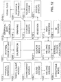
- Fig. 12 illustrates an example embodiment of a functional block diagram of the system 100 of Fig. 1 .
- the various functional blocks of the system 100 as shown in Fig. 12 are implemented largely via software instructions and modules running on the PPS 110.
- the various functional blocks of the system 100 include a physical interface 1201, torch and clamp models 1202, environment models 1203, sound content functionality 1204, welding sounds 1205, stand/table model 1206, internal architecture functionality 1207, calibration functionality 1208, coupon models 1210, welding physics 1211, internal physics adjustment tool (tweaker) 1212, graphical user interface functionality 1213, graphing functionality 1214, student reports functionality 1215, renderer 1216, bead rendering 1217, 3D textures 1218, visual cues functionality 1219, scoring and tolerance functionality 1220, tolerance editor 1221, and special effects 1222.
- the internal architecture functionality 1207 provides the higher level software logistics of the processes of the system 100 including, for example, loading files, holding information, managing threads, turning the physics model on, and triggering menus.
- the internal architecture functionality 1207 runs on the CPU 111, in accordance with an embodiment of the present invention.
- Certain real-time inputs to the PPS 110 include arc location, gun position, FMDD or helmet position, gun on/off state, and contact made state (yes/no).
- the graphical user interface functionality 1213 allows a user, through the ODD 150 using the joystick 132 of the physical user interface 130, to set up a welding scenario.
- the set up of a welding scenario includes selecting a language, entering a user name, selecting a practice plate (i.e., a welding coupon), selecting a welding process (e.g., FCAW, GMAW, SMAW) and associated axial spray, pulse, or short arc methods, selecting a gas type and flow rate, selecting a type of stick electrode (e.g., 6010 or 7018), and selecting a type of flux cored wire (e.g., self-shielded, gas-shielded).
- the set up of a welding scenario also includes selecting a table height, an arm height, an arm position, and an arm rotation of the T/S 170.
- the set up of a welding scenario further includes selecting an environment (e.g., a background environment in virtual reality space), setting a wire feed speed, setting a voltage level, setting an amperage, selecting a polarity, and turning particular visual cues on or off.
- the graphing functionality 1214 gathers user performance parameters and provides the user performance parameters to the graphical user interface functionality 1213 for display in a graphical format (e.g., on the ODD 150 ). Tracking information from the ST 120 feeds into the graphing functionality 1214.
- the graphing functionality 1214 includes a simple analysis module (SAM) and a whip/weave analysis module (WWAM).
- SAM analyzes user welding parameters including welding travel angle, travel speed, weld angle, position, and tip to work distance by comparing the welding parameters to data stored in bead tables.
- the WWAM analyzes user whipping parameters including dime spacing, whip time, and puddle time.
- the WWAM also analyzes user weaving parameters including width of weave, weave spacing, and weave timing.
- the SAM and WWAM interpret raw input data (e.g., position and orientation data) into functionally usable data for graphing.
- a tolerance window is defined by parameter limits around an optimum or ideal set point input into bead tables using the tolerance editor 1221, and scoring and tolerance functionality 1220 is performed.
- the tolerance editor 1221 includes a weldometer which approximates material usage, electrical usage, and welding time. Furthermore, when certain parameters are out of tolerance, welding discontinuities (i.e., welding defects) may occur. The state of any welding discontinuities are processed by the graphing functionality 1214 and presented via the graphical user interface functionality 1213 in a graphical format. Such welding discontinuities include improper weld size, poor bead placement, concave bead, excessive convexity, undercut, porosity, incomplete fusion, slag entrapment, overfill, burnthrough, and excessive spatter. In accordance with an embodiment of the present invention, the level or amount of a discontinuity is dependent on how far away a particular user parameter is from the optimum or ideal set point.
- the scoring and tolerance functionality 1220 provide number scores depending on how close to optimum (ideal) a user is for a particular parameter and depending on the level of discontinuities or defects present in the weld. The optimum values are derived from real-world data. Information from the scoring and tolerance functionality 1220 and from the graphics functionality 1214 may be used by the student reports functionality 1215 to create a performance report for an instructor and/or a student.
- the system 100 is capable of analyzing and displaying the results of virtual welding activity. By analyzing the results, it is meant that system 100 is capable of determining when during the welding pass and where along the weld joints, the user deviated from the acceptable limits of the welding process.
- a score may be attributed to the user's performance. In one embodiment, the score may be a function of deviation in position, orientation and speed of the mock welding tool 160 through ranges of tolerances, which may extend from an ideal welding pass to marginal or unacceptable welding activity. Any gradient of ranges may be incorporated into the system 100 as chosen for scoring the user's performance. Scoring may be displayed numerically or alpha-numerically.
- the user's performance may be displayed graphically showing, in time and/or position along the weld joint, how closely the mock welding tool traversed the weld joint.
- Parameters such as travel angle, work angle, speed, and distance from the weld joint are examples of what may be measured, although any parameters may be analyzed for scoring purposes.
- the tolerance ranges of the parameters are taken from real-world welding data, thereby providing accurate feedback as to how the user will perform in the real world.
- analysis of the defects corresponding to the user's performance may also be incorporated and displayed on the ODD 150.
- a graph may be depicted indicating what type of discontinuity resulted from measuring the various parameters monitored during the virtual welding activity. While occlusions may not be visible on the ODD 150, defects may still have occurred as a result of the user's performance, the results of which may still be correspondingly displayed, i.e. graphed.
- Visual cues functionality 1219 provide immediate feedback to the user by displaying overlaid colors and indicators on the FMDD 140 and/or the ODD 150.
- Visual cues are provided for each of the welding parameters 151 including position, tip to work distance, weld angle, travel angle, travel speed, and arc length (e.g., for stick welding) and visually indicate to the user if some aspect of the user's welding technique should be adjusted based on the predefined limits or tolerances.
- Visual cues may also be provided for whip/weave technique and weld bead "dime" spacing, for example. Visual cues may be set independently or in any desired combination.
- Calibration functionality 1208 provides the capability to match up physical components in real world space (3D frame of reference) with visual components in virtual reality space.
- Each different type of welding coupon (WC) is calibrated in the factory by mounting the WC to the arm 173 of the T/S 170 and touching the WC at predefined points (indicated by, for example, three dimples on the WC) with a calibration stylus operatively connected to the ST 120.
- the ST 120 reads the magnetic field intensities at the predefined points, provides position information to the PPS 110, and the PPS 110 uses the position information to perform the calibration (i.e., the translation from real world space to virtual reality space).
- any particular type of WC fits into the arm 173 of the T/S 170 in the same repeatable way to within very tight tolerances. Therefore, once a particular WC type is calibrated, that WC type does not have to be re-calibrated (i.e., calibration of a particular type of WC is a one-time event). WCs of the same type are interchangeable. Calibration ensures that physical feedback perceived by the user during a welding process matches up with what is displayed to the user in virtual reality space, making the simulation seem more real. For example, if the user slides the tip of a MWT 160 around the corner of a actual WC 180, the user will see the tip sliding around the corner of the virtual WC on the FMDD 140 as the user feels the tip sliding around the actual corner. In accordance with an embodiment of the present invention, the MWT 160 is placed in a pre-positioned jig and is calibrated as well, based on the known jig position.
- “smart” coupons are provided, having sensors on, for example, the corners of the coupons.
- the ST 120 is able to track the corners of a "smart” coupon such that the system 100 continuously knows where the "smart" coupon is in real world 3D space.
- licensing keys are provided to "unlock" welding coupons. When a particular WC is purchased, a licensing key is provided allowing the user to enter the licensing key into the system 100, unlocking the software associated with that WC.
- special non-standard welding coupons may be provided based on real-world CAD drawings of parts. Users may be able to train on welding a CAD part even before the part is actually produced in the real world.
- Sound content functionality 1204 and welding sounds 1205 provide particular types of welding sounds that change depending on if certain welding parameters are within tolerance or out of tolerance. Sounds are tailored to the various welding processes and parameters. For example, in a MIG spray arc welding process, a crackling sound is provided when the user does not have the MWT 160 positioned correctly, and a hissing sound is provided when the MWT 160 is positioned correctly. In a short arc welding process, a steady crackling or frying sound is provided for proper welding technique, and a hissing sound may be provided when undercutting is occurring. These sounds mimic real world sounds corresponding to correct and incorrect welding technique.
- High fidelity sound content may be taken from real world recordings of actual welding using a variety of electronic and mechanical means, in accordance with various embodiments of the present invention.
- the perceived volume and directionality of sound is modified depending on the position, orientation, and distance of the user's head (assuming the user is wearing a FMDD 140 that is tracked by the ST 120 ) with respect to the simulated arc between the MWT 160 and the WC 180.
- Sound may be provided to the user via ear bud speakers 910 in the FMDD 140 or via speakers configured in the console 135 or T/S 170, for example.
- Environment models 1203 are provided to provide various background scenes (still and moving) in virtual reality space.
- Such background environments may include, for example, an indoor welding shop, an outdoor race track, a garage, etc. and may include moving cars, people, birds, clouds, and various environmental sounds.
- the background environment may be interactive, in accordance with an embodiment of the present invention. For example, a user may have to survey a background area, before starting welding, to ensure that the environment is appropriate (e.g., safe) for welding.
- Torch and clamp models 1202 are provided which model various MWTs 160 including, for example, guns, holders with stick electrodes, etc. in viruatl reality space.
- Coupon models 1210 are provided which model various WCs 180 including, for example, flat plate coupons, T-joint coupons, butt-joint coupons, groove-weld coupons, and pipe coupons (e.g., 2-inch diameter pipe and 6-inch diameter pipe) in virtual reality space.
- a stand/table model 1206 is provided which models the various parts of the T/S 170 including an adjustable table 171, a stand 172, an adjustable arm 173, and a vertical post 174 in virtual reality space.
- a physical interface model 1201 is provided which models the various parts of the welding user interface 130, console 135, and ODD 150 in virtual reality space.
- simulation of a weld puddle or pool in virtual reality space is accomplished where the simulated weld puddle has real-time molten metal fluidity and heat dissipation characteristics.
- the welding physics functionality 1211 a.k.a., the physics model
- the welding physics functionality employs a double displacement layer technique to accurately model dynamic fluidity/viscosity, solidity, heat gradient (heat absorption and dissipation), puddle wake, and bead shape, and is described in more detail herein with respect to Figs. 14A-14C .
- the welding physics functionality 1211 communicates with the bead rendering functionality 1217 to render a weld bead in all states from the heated molten state to the cooled solidified state.
- the bead rendering functionality 1217 uses information from the welding physics functionality 1211 (e.g., heat, fluidity, displacement, dime spacing) to accurately and realistically render a weld bead in virtual reality space in real-time.
- the 3D textures functionality 1218 provides texture maps to the bead rendering functionality 1217 to overlay additional textures (e.g., scorching, slag, grain) onto the simulated weld bead.
- slag may be shown rendered over a weld bead during and just after a welding process, and then removed to reveal the underlying weld bead.
- the renderer functionality 1216 is used to render various non-puddle specific characteristics using information from the special effects module 1222 including sparks, spatter, smoke, arc glow, fumes and gases, and certain discontinuities such as, for example, undercut and porosity.
- the internal physics adjustment tool 1212 is a tweaking tool that allows various welding physics parameters to be defined, updated, and modified for the various welding processes.
- the internal physics adjustment tool 1212 runs on the CPU 111 and the adjusted or updated parameters are downloaded to the GPUs 115.
- the types of parameters that may be adjusted via the internal physics adjustment tool 1212 include parameters related to welding coupons, process parameters that allow a process to be changed without having to reset a welding coupon (allows for doing a second pass), various global parameters that can be changed without resetting the entire simulation, and other various parameters.
- Fig. 13 is a flow chart of an embodiment of a method 1300 of training using the virtual reality training system 100 of Fig. 1 .
- step 1310 move a mock welding tool with respect to a welding coupon in accordance with a welding technique.
- step 1320 track position and orientation of the mock welding tool in three-dimensional space using a virtual reality system.
- step 1330 view a display of the virtual reality welding system showing a real-time virtual reality simulation of the mock welding tool and the welding coupon in a virtual reality space as the simulated mock welding tool deposits a simulated weld bead material onto at least one simulated surface of the simulated welding coupon by forming a simulated weld puddle in the vicinity of a simulated arc emitting from said simulated mock welding tool.
- step 1340 view on the display, real-time molten metal fluidity and heat dissipation characteristics of the simulated weld puddle.
- step 1350 modify in real-time, at least one aspect of the welding technique in response to viewing the real-time molten metal fluidity and heat dissipation characteristics of the simulated weld puddle.
- the method 1300 illustrates how a user is able to view a weld puddle in virtual reality space and modify his welding technique in response to viewing various characteristics of the simulated weld puddle, including real-time molten metal fluidity (e.g., viscosity) and heat dissipation.
- the user may also view and respond to other characteristics including real-time puddle wake and dime spacing. Viewing and responding to characteristics of the weld puddle is how most welding operations are actually performed in the real world.
- the double displacement layer modeling of the welding physics functionality 1211 run on the GPUs 115 allows for such real-time molten metal fluidity and heat dissipation characteristics to be accurately modeled and represented to the user. For example, heat dissipation determines solidification time (i.e., how much time it takes for a wexel to completely solidify).
- a user may make a second pass over the weld bead material using the same or a different (e.g., a second) mock welding tool and/or welding process.
- the simulation shows the simulated mock welding tool, the welding coupon, and the original simulated weld bead material in virtual reality space as the simulated mock welding tool deposits a second simulated weld bead material merging with the first simulated weld bead material by forming a second simulated weld puddle in the vicinity of a simulated arc emitting from the simulated mock welding tool. Additional subsequent passes using the same or different welding tools or processes may be made in a similar manner.
- weld bead and base material may include mild steel, stainless steel, aluminum, nickel based alloys, or other materials.
- Figs. 14A-14B illustrate the concept of a welding element (wexel) displacement map 1420, in accordance with an embodiment of the present invention.
- Fig. 14A shows a side view of a flat welding coupon (WC) 1400 having a flat top surface 1410.
- the welding coupon 1400 exists in the real world as, for example, a plastic part, and also exists in virtual reality space as a simulated welding coupon.
- Fig. 14B shows a representation of the top surface 1410 of the simulated WC 1400 broken up into a grid or array of welding elements (i.e., wexels) forming a wexel map 1420.
- Each wexel (e.g., wexel 1421 ) defines a small portion of the surface 1410 of the welding coupon.
- the wexel map defines the surface resolution.
- Changeable channel parameter values are assigned to each wexel, allowing values of each wexel to dynamically change in real-time in virtual reality weld space during a simulated welding process.
- the changeable channel parameter values correspond to the channels Puddle (molten metal fluidity/viscosity displacement), Heat (heat absorption/dissipation), Displacement (solid displacement), and Extra (various extra states, e.g., slag, grain, scorching, virgin metal).
- PHED molten metal fluidity/viscosity displacement
- Heat heat absorption/dissipation
- Displacement solid displacement
- Extra variable extra states, e.g., slag, grain, scorching, virgin metal.
- Fig. 15 illustrates an example embodiment of a coupon space and a weld space of the flat welding coupon (WC) 1400 of Fig. 14 simulated in the system 100 of Fig. 1 .
- Points O, X, Y, and Z define the local 3D coupon space.
- each coupon type defines the mapping from 3D coupon space to 2D virtual reality weld space.
- the wexel map 1420 of Fig. 14 is a two-dimensional array of values that map to weld space in virtual reality.
- a user is to weld from point B to point E as shown in Fig. 15 .
- a trajectory line from point B to point E is shown in both 3D coupon space and 2D weld space in Fig. 15 .
- Each type of coupon defines the direction of displacement for each location in the wexel map.
- the direction of displacement is the same at all locations in the wexel map (i.e., in the Z-direction).
- the texture coordinates of the wexel map are shown as S, T (sometimes called U, V) in both 3D coupon space and 2D weld space, in order to clarify the mapping.
- the wexel map is mapped to and represents the rectangular surface 1410 of the welding coupon 1400.
- Fig. 16 illustrates an example embodiment of a coupon space and a weld space of a corner (tee joint) welding coupon (WC) 1600 simulated in the system 100 of Fig. 1 .
- the corner WC 1600 has two surfaces 1610 and 1620 in 3D coupon space that are mapped to 2D weld space as shown in Fig. 16 .
- points O, X, Y, and Z define the local 3D coupon space.
- the texture coordinates of the wexel map are shown as S, T in both 3D coupon space and 2D weld space, in order to clarify the mapping.
- a user is to weld from point B to point E as shown in Fig. 16 .
- a trajectory line from point B to point E is shown in both 3D coupon space and 2D weld space in Fig. 16 .
- the direction of displacement is towards the line X'-O' as shown in the 3D coupon space, towards the opposite corner as shown in Fig. 16 .
- Fig. 17 illustrates an example embodiment of a coupon space and a weld space of a pipe welding coupon (WC) 1700 simulated in the system 100 of Fig. 1 .
- the pipe WC 1700 has a curved surface 1710 in 3D coupon space that is mapped to 2D weld space as shown in Fig. 17 .
- points O, X, Y, and Z define the local 3D coupon space.
- the texture coordinates of the wexel map are shown as S, T in both 3D coupon space and 2D weld space, in order to clarify the mapping.
- a user is to weld from point B to point E along a curved trajectory as shown in Fig. 17 .
- FIG. 17 A trajectory curve and line from point B to point E is shown in 3D coupon space and 2D weld space, respectively, in Fig. 17 .
- the direction of displacement is away from the line Y-O (i.e., away from the center of the pipe).
- Fig. 18 illustrates an example embodiment of the pipe welding coupon (WC) 1700 of Fig. 17 .
- the pipe WC 1700 is made of a non-ferric, non-conductive plastic and simulates two pipe pieces 1701 and 1702 coming together to form a root joint 1703.
- An attachment piece 1704 for attaching to the arm 173 of the T/S 170 is also shown.
- a weldable wexel map may be mapped to a rectangular surface of a welding coupon.
- Each element of the weldable map is termed a wexel in the same sense that each element of a picture is termed a pixel (a contraction of picture element).
- a pixel contains channels of information that define a color (e.g., red, green, blue, etc.).
- a wexel contains channels of information (e.g., P, H, E, D) that define a weldable surface in virtual reality space.
- the format of a wexel is summarized as channels PHED (Puddle, Heat, Extra, Displacement) which contains four floating point numbers.
- the Extra channel is treated as a set of bits which store logical information about the wexel such as, for example, whether or not there is any slag at the wexel location.
- the Puddle channel stores a displacement value for any liquefied metal at the wexel location.
- the Displacement channel stores a displacement value for the solidified metal at the wexel location.
- the Heat channel stores a value giving the magnitude of heat at the wexel location.
- the weldable part of the coupon can show displacement due to a welded bead, a shimmering surface "puddle” due to liquid metal, color due to heat, etc. All of these effects are achieved by the vertex and pixel shaders applied to the weldable surface.
- a displacement map and a particle system are used where the particles can interact with each other and collide with the displacement map.
- the particles are virtual dynamic fluid particles and provide the liquid behavior of the weld puddle but are not rendered directly (i.e., are not visually seen directly). Instead, only the particle effects on the displacement map are visually seen.
- Heat input to a wexel affects the movement of nearby particles.
- Puddle displacement is the liquid metal of the weld which changes rapidly (e.g., shimmers) and can be thought of as being "on top" of the Displacement.
- the particles overlay a portion of a virtual surface displacement map (i.e., a wexel map).
- the Displacement represents the permanent solid metal including both the initial base metal and the weld bead that has solidified.
- the simulated welding process in virtual reality space works as follows: Particles stream from the emitter (emitter of the simulated MWT 160 ) in a thin cone. The particles make first contact with the surface of the simulated welding coupon where the surface is defined by a wexel map. The particles interact with each other and the wexel map and build up in real-time. More heat is added the nearer a wexel is to the emitter. Heat is modeled in dependence on distance from the arc point and the amount of time that heat is input from the arc. Certain visuals (e.g., color, etc.) are driven by the heat. A weld puddle is drawn or rendered in virtual reality space for wexels having enough heat.
- the wexel map liquefies, causing the Puddle displacement to "raise up” for those wexel locations.
- Puddle displacement is determined by sampling the "highest" particles at each wexel location. As the emitter moves on along the weld trajectory, the wexel locations left behind cool. Heat is removed from a wexel location at a particular rate. When a cooling threshold is reached, the wexel map solidifies. As such, the Puddle displacement is gradually converted to Displacement (i.e., a solidified bead). Displacement added is equivalent to Puddle removed such that the overall height does not change. Particle lifetimes are tweaked or adjusted to persist until solidification is complete. Certain particle properties that are modeled in the system 100 include attraction/repulsion, velocity (related to heat), dampening (related to heat dissipation), direction (related to gravity).
- Figs. 19A-19C illustrate an example embodiment of the concept of a dual-displacement (displacement and particles) puddle model of the system 100 of Fig. 1 .
- Welding coupons are simulated in virtual reality space having at least one surface.
- the surfaces of the welding coupon are simulated in virtual reality space as a double displacement layer including a solid displacement layer and a puddle displacement layer.
- the puddle displacement layer is capable of modifying the solid displacement layer.
- puddle is defined by an area of the wexel map where the Puddle value has been raised up by the presence of particles.
- the sampling process is represented in Figs. 19A-19C .
- a section of a wexel map is shown having seven adjacent wexels.
- the current Displacement values are represented by un-shaded rectangular bars 1910 of a given height (i.e., a given displacement for each wexel).
- the particles 1920 are shown as round un-shaded dots colliding with the current Displacement levels and are piled up.
- the "highest" particle heights 1930 are sampled at each wexel location.
- Fig. 19A the particles 1920 are shown as round un-shaded dots colliding with the current Displacement levels and are piled up.
- the "highest" particle heights 1930 are sampled at each wexel location.
- the shaded rectangles 1940 show how much Puddle has been added on top of the Displacement as a result of the particles.
- the weld puddle height is not instantly set to the sampled values since Puddle is added at a particular liquification rate based on Heat.
- real-time molten metal fluidity characteristics are accurately simulated.
- the user is able to observe the molten metal fluidity characteristics and the heat dissipation characteristics of the weld puddle in real-time in virtual reality space and use this information to adjust or maintain his welding technique.
- the number of wexels representing the surface of a welding coupon is fixed. Furthermore, the puddle particles that are generated by the simulation to model fluidity are temporary, as described herein. Therefore, once an initial puddle is generated in virtual reality space during a simulated welding process using the system 100, the number of wexels plus puddle particles tends to remain relatively constant. This is because the number of wexels that are being processed is fixed and the number of puddle particles that exist and are being processed during the welding process tend to remain relatively constant because puddle particles are being created and "destroyed" at a similar rate (i.e., the puddle particles are temporary). Therefore, the processing load of the PPS 110 remains relatively constant during a simulated welding session.
- puddle particles may be generated within or below the surface of the welding coupon.
- displacement may be modeled as being positive or negative with respect to the original surface displacement of a virgin (i.e., un-welded) coupon.
- puddle particles may not only build up on the surface of a welding coupon, but may also penetrate the welding coupon.
- the number of wexels is still fixed and the puddle particles being created and destroyed is still relatively constant.
- a wexel displacement map may be provided having more channels to model the fluidity of the puddle.
- a dense voxel map may be modeled.
- only particles may be modeled which are sampled and never go away.
- Such alternative embodiments may not provide a relatively constant processing load for the system, however.
- blow-through or a keyhole is simulated by taking material away. For example, if a user keeps an arc in the same location for too long, in the real world, the material would burn away causing a hole.
- Such real-world burnthrough is simulated in the system 100 by wexel decimation techniques. If the amount of heat absorbed by a wexel is determined to be too high by the system 100, that wexel may be flagged or designated as being burned away and rendered as such (e.g., rendered as a hole). Subsequently, however, wexel re-constitution may occur for certain welding processs (e.g., pipe welding) where material is added back after being initially burned away.
- the system 100 simulates wexel decimation (taking material away) and wexel reconstitution (i.e., adding material back). Furthermore, removing material in root-pass welding is properly simulated in the system 100.
- removing material in root-pass welding is properly simulated in the system 100.
- grinding of the root pass may be performed prior to subsequent welding passes.
- system 100 may simulate a grinding pass that removes material from the virtual weld joint.
- the material removed may be modeled as a negative displacement on the wexel map. That is to say that the grinding pass removes material that is modeled by the system 100 resulting in an altered bead contour.
- Simulation of the grinding pass may be automatic, which is to say that the system 100 removes a predetermined thickness of material, which may be respective to the surface of the root pass weld bead.
- an actual grinding tool may be simulated that turns on and off by activation of the mock welding tool 160 or another input device. It is noted that the grinding tool may be simulated to resemble a real world grinder. In this embodiment, the user maneuvers the grinding tool along the root pass to remove material responsive to the movement thereof. It will be understood that the user may be allowed to remove too much material. In a manner similar to that described above, holes or other defects (described above) may result if the user grinds away too much material. Still, hard limits or stops may be implemented, i.e. programmed, to prevent the user from removing too much material or indicate when too much material is being removed.
- the system 100 also uses three other types of visible particles to represent Arc, Flame, and Spark effects, in accordance with an embodiment of the present invention. These types of particles do not interact with other particles of any type but interact only with the displacement map. While these particles do collide with the simulated weld surface, they do not interact with each other. Only Puddle particles interact with each other, in accordance with an embodiment of the present invention.
- the physics of the Spark particles is setup such that the Spark particles bounce around and are rendered as glowing dots in virtual reality space.
- the physics of the Arc particles is setup such that the Arc particles hit the surface of the simulated coupon or weld bead and stay for a while.
- the Arc particles are rendered as larger dim bluish-white spots in virtual reality space. It takes many such spots superimposed to form any sort of visual image. The end result is a white glowing nimbus with blue edges.
- the physics of the Flame particles is modeled to slowly raise upward.
- the Flame particles are rendered as medium sized dim red-yellow spots. It takes many such spots superimposed to form any sort of visual image. The end result is blobs of orange-red flames with red edges raising upward and fading out.
- Other types of non-puddle particles may be implemented in the system 100, in accordance with other embodiments of the present invenntion.
- smoke particles may be modeled and simulated in a similar manner to flame particles.
- the final steps in the simulated visualization are handled by the vertex and pixel shaders provided by the shaders 117 of the GPUs 115.
- the vertex and pixel shaders apply Puddle and Displacement, as well as surface colors and reflectivity altered due to heat, etc.
- the Extra (E) channel of the PHED wexel format contains all of the extra information used per wexel.
- a slag bit an undercut value (amount of undercut at this wexel where zero equals no undercut)
- a porosity value amount of porosity at this wexel where zero equals no porosity
- bead wake value which encodes the time at which the bead solidifies.
- image maps associated with different coupon visuals including virgin steel, slag, bead, and porosity. These image maps are used both for bump mapping and texture mapping. The amount of blending of these image maps is
- a bead wake effect is achieved using a 1D image map and a per wexel bead wake value that encodes the time at which a given bit of bead is solidified. Once a hot puddle wexel location is no longer hot enough to be called “puddle”, a time is saved at that location and is called “bead wake”. The end result is that the shader code is able to use the 1D texture map to draw the "ripples" that give a bead its unique appearance which portrays the direction in which the bead was laid down.
- the system 100 is capable of simulating, in virtual reality space, and displaying a weld bead having a real-time weld bead wake characteristic resulting from a real-time fluidity-to-solidification transition of the simulated weld puddle, as the simulated weld puddle is moved along a weld trajectory.
- the system 100 is capable of teaching a user how to troubleshoot a welding machine.
- a troubleshooting mode of the system may train a user to make sure he sets up the system correctly (e.g., correct gas flow rate, correct power cord connected, etc.)
- the system 100 is capable of recording and playing back a welding session (or at least a portion of a welding session, for example, N frames).
- a track ball may be provided to scroll through frames of video, allowing a user or instructor to critique a welding session. Playback may be provided at selectable speeds as well (e.g., full speed, half speed, quarter speed).
- a split-screen playback may be provided, allowing two welding sessions to be viewed side-by-side, for example, on the ODD 150. For example, a "good” welding session may be viewed next to a “poor” welding session for comparison purposes.
- a real-time virtual reality welding system including a programmable processor-based subsystem, a spatial tracker operatively connected to the programmable processor-based subsystem, at least one mock welding tool capable of being spatially tracked by the spatial tracker, and at least one display device operatively connected to the programmable processor-based subsystem.
- the system is capable of simulating, in virtual reality space, a weld puddle having real-time molten metal fluidity and heat dissipation characteristics.
- the system is further capable of displaying the simulated weld puddle on the display device in real-time.
- One embodiment provides a virtual reality arc welding system.
- the system includes a programmable processor-based subsystem, a spatial tracker operatively connected to the programmable processor-based subsystem, at least one wireless mock welding tool configured to wirelessly communicate with the programmable processor-based subsystem and the spatial tracker, and at least one wireless face-mounted display device configured to wirelessly communicate with the programmable processor-based subsystem and the spatial tracker.
- a wireless mock welding tool and a wireless face-mounted display may provide the user of the system with more mobility and flexibility during a simulated welding process.
- the system is configured to simulate, in a virtual reality environment, a weld puddle having real-time molten metal fluidity and heat dissipation characteristics, and display the simulated weld puddle on the at least one wireless face-mounted display device in real time.
- the system may also include a wireless hub device communicatively wired to the programmable processor-based subsystem and the spatial tracker, wherein the at least one wireless mock welding tool and the at least one wireless face-mounted display device each wirelessly communicate with the programmable processor-based subsystem and the spatial tracker through the wireless hub device.
- the system may further include a mock welding cable attached to the at least one mock welding tool and configured to simulate at least a weight and a stiffness of a real welding cable.
- Fig. 20 illustrates a second example embodiment of a system block diagram of a system 2000 providing arc welding training in a real-time virtual reality environment.
- the system 2000 is similar to the system 100 of Fig. 1 .
- the system 2000 includes a wireless hub device 2010 that is operatively wired to the PPS 110 and the ST 120 to communicate with each, respectively.
- the wireless hub device 2010 allows any truly wireless component of the system 2000 to communicate with the PPS 110 and/or the ST 120.
- the mock welding tool (MWT) 160 is wireless and the face-mounted display device (FMDD) 140 is wireless and each communicate with the PPS 110 and the ST 120 via the wireless hub device 2010.
- Other optional elements of the system may be wireless as well such as, for example, a foot pedal device for controlling simulated welding current for a gas tungsten arc welding simulation.
- the wireless hub device 2010 is not present and, instead, the PPS 110 and the ST 120 are each configured to wirelessly communicate directly with the wireless FMDD 140 and/or the wireless MWT 160.
- Wireless communication as discussed herein, may be accomplished through any of various types of wireless technologies including radio frequency technologies such as, for example, WiFi or Bluetooth®. Other wireless technologies such as, for example, infrared technologies or acoustic technologies may also be employed, in accordance with various other embodiments.
- a mock welding cable 2020 may be attached to the wireless mock welding tool to simulate a weight and a stiffness of a real welding cable. In this manner, a welding student would not be mislead by the ease-of-use of a wireless mock welding tool without such a mock welding cable.
- Another embodiment provides a method of using a virtual reality welding system.
- the method includes displaying an image of a virtual weld joint having a weld bead, on a display device of a virtual reality welding system, that was generated using the virtual reality welding system.
- the method further includes scrolling across a length dimension of the image of the virtual weld joint using a user interface of the virtual reality welding system, and displaying an image of a cross-sectional area through the virtual weld joint at successive locations along the length dimension of the image of the virtual weld joint on the display device of the virtual reality welding system in response to the scrolling.
- the method may also include displaying a cross-section indicator on the display device of the virtual reality welding system indicating a location along the length dimension of the image of the virtual weld joint corresponding to the image of the displayed cross-sectional area.
- the method may further include stopping the scrolling at a location along the length dimension of the image of the virtual weld joint and observing a displayed image of a cross-sectional area through the virtual weld joint at the location.
- a displayed image of the cross-sectional area through the virtual weld joint at a location along the length dimension of the image of the virtual weld joint may show welding characteristics of the virtual weld joint at the location as simulated by the virtual reality welding system.
- the welding characteristics may include, for example, virtual penetration into a virtual welding coupon and internal defects and discontinuities, as simulated by the virtual reality welding system.
- the method may also include automatically looping in time across a length dimension of the image of the virtual weld joint between a first location and a second location, successively displaying in time during the looping an image of the cross-sectional area through the virtual weld joint at each of a plurality of defined locations spanning from the first location to the second location.
- Fig. 21 illustrates a displayed image of a virtual weld joint 2100 having a weld bead appearance that may be displayed on a display device of a virtual reality welding system (e.g., the system 100 ).
- the virtual weld joint 2100 is generated using the virtual reality welding system and is represented within the virtual reality welding system as stored data being representative of the virtual weld joint 2100 in three-dimensions. Therefore, the virtual weld joint 2100 is represented within the virtual reality welding system as having both external and internal characteristics.
- the external characteristics may include, for example, shape, color, slag, size, and stacked dimes appearance.
- the internal characteristics may include, for example, an amount of penetration into a virtual welding coupon and internal defects and discontinuities, properly represented in three-dimensions.
- the internal and external characteristics of the virtual weld joint 2100 are a result of the virtual welding process that created the virtual weld joint 2100, including user technique and the modeled physics and metallurgical properties simulated in real time in the virtual reality welding system.
- a user may use a portion of the user interface 130 or 150 (e.g., a trackball, a knob, a button, a joystick, or a user's finger dragged across a touch-screen display device) to scroll a cross-section indicator 2110 across a length dimension 2120 of the displayed image of the virtual weld joint in one direction or the other.
- a cross-section indicator 2110 is shown as a displayed dotted line intersecting the displayed virtual weld joint 2100 at a particular location.
- the virtual reality welding system Based on the location of the cross-section indicator 2110 along the length of the image of the virtual weld joint 2100, the virtual reality welding system displays an image of the cross-sectional area 2130 of the virtual weld joint 2100 at that location showing the internal characteristics of the virtual weld joint. As the user moves the location of the cross-section indicator 2110 along the length of the image of the virtual weld joint 2100, a different image of a different cross-sectional area corresponding to the new location is displayed. In accordance with an embodiment, a defined number of equally spaced images of cross-sectional areas are generated by the virtual reality welding system across the length dimension 2120 of the virtual weld joint 2100. The cross-sectional images may be generated automatically as the virtual weld joint 2100 is formed, or after the virtual weld joint 2100 is formed, for example, upon command of the user.
- a user may scroll across the length of the image of the virtual weld joint to selectively display and observe the internal characteristics of the virtual weld joint at different locations.
- a user may find that the internal characteristics along one part of the virtual weld joint are much better than the internal characteristics along another part of the virtual weld joint, even though the external characteristics may look fine along both parts.
- the user may then explore how to change one or more aspects of his welding technique to improve the internal characteristics across the entire weld joint.
- Fig. 22 illustrates the displayed image of the virtual weld joint 2100 of Fig. 21 having a weld bead appearance, that may be displayed on a display device of a virtual reality welding system.
- a user may employ a user interface of the virtual reality welding system to designate a first location " A " and a second location "B" along the length dimension 2120 of the image of the virtual weld joint 2100 over which the cross-section indicator 2110 may loop.
- the virtual reality welding system may be commanded to automatically loop in time across the length dimension 2120 of the image of the virtual reality weld joint 2100 between the first location "A” and the second location "B", successively displaying in time during the looping an image of a cross-sectional area 2130 through the virtual weld joint 2100 at each of a plurality of defined locations spanning from the first location "A" to the second location "B".
- the number of defined locations and corresponding images of cross-sectional areas between location "A" and location "B” depend on the resolution and data processing capability of the virtual reality welding system. For example, in accordance with an embodiment, there may be sixty-four (64) equally spaced defined locations from the first location "A" to the second location "B". As a result, the virtual reality welding system may loop through sixty-four (64) unique images of corresponding cross-sectional areas of the virtual weld joint 2100. In accordance with an embodiment, a user may be able to scroll and loop along the circumference dimension of a virtual weld joint of a pipe in a similar manner to view cross-sectional areas. Again, the cross-sectional images may be generated automatically as the virtual weld joint 2100 is formed, or after the virtual weld joint 2100 is formed, for example, upon command of the user.
- a further embodiment provides a method of using a virtual reality welding system.
- the method includes generating a virtual weld joint having a virtual weld bead using a virtual reality welding system.
- the virtual weld joint is represented within the virtual reality welding system as a first digital data set.
- the method further includes generating a three-dimensional (3D) digital model representative of at least a portion of the virtual weld joint using the first digital data set on the virtual reality welding system, wherein the 3D digital model is operatively compatible with a 3D printing system.
- the method may also include transferring the 3D digital model to the 3D printing system, and printing a 3D physical model representative of at least a portion of the virtual weld joint using the 3D digital model on the 3D printing system.
- the 3D physical model may be made of at least one of a plastic material, a metal material, or a ceramic material.
- the virtual weld joint may include a virtual welding coupon as modified by the virtual weld bead.
- the 3D printing system may be in operative communication with the virtual reality welding system and the transferring of the 3D digital model may be accomplished via the operative communication.
- the operative communication between the virtual reality welding system and the 3D printing system may be via a wired means or via, at least in part, a wireless means.
- Fig. 23 illustrates a virtual reality welding system 2300 in operative communication with a 3D printing system 2350.
- the virtual reality welding system 2300 is similar to the system 100 of Fig. 1 .
- the system 2300 is further configured to generate a 3D digital model 2310 representative of at least a portion of a virtual weld joint and communicate the 3D digital model 2310 (e.g., in the form of a digital file) to a 3D printing system.
- the virtual weld joint is initially generated using the virtual reality welding system 2300 and is represented within the virtual reality welding system (e.g., stored in memory) as a first digital data set.
- the first digital data set includes the same type of data generated by the system 100 of Fig. 1 when generating a virtual weld joint.
- the virtual reality welding system 2300 is further configured to process the first digital data set to generate the 3D digital model 2310.
- the 3D digital model 2310 is a computer-aided design (CAD) model, for example. Other types of 3D digital models may be possible as well, in accordance with various other embodiments.
- the PPS 110 of the virtual reality welding system 2300 employs a conversion software module specifically programmed to read the first digital data set and convert the first digital data set to the 3D digital model 2310.
- the term "3D digital model" as used herein refers to data and/or instructions that are in a digital format (e.g., a digital electronic format stored on a computer-readable medium) that may be read by a computer-based or processor-based apparatus such as the 3D printing system 2300. Once the 3D digital model 2310 is generated, the model 2310 may be transferred to the 3D printing system 2350 for 3D printing as long as the model 2310 is compatible with the 3D printing system 2350.
- the virtual reality welding system 2300 includes a communication device 2320.
- the communication device 2320 is operatively connected to the programmable processor-based subsystem 110 of the virtual reality welding system 2300 and provides all of the circuitry and/or software for transmitting data in a digitally communicated manner.
- the communication device 2320 may include an Ethernet port and Ethernet-capable transmitting circuitry.
- the communication device 2320 may provide a wireless BluetoothTM communication connection.
- the communication device 2320 may be a device that accepts and writes to a non-transitory computer-readable medium such as a computer disk or a flash drive data storage device, for example.
- the communication device 2320 may be a modem device providing connection to the internet. Other types of communication devices are possible as well, in accordance with various embodiments.
- the 3D printing system 2350 is operatively compatible with the communication device 2320.
- the 3D printing system 2350 may be a commercially available system where the virtual reality welding system 2300 is configured to be compatible with the 3D printing system 2350, in accordance with an embodiment.
- the 3D printing system prints a physical model 2355 by spraying or otherwise transferring a material substance in multiple layers onto a construction surface, beginning with a bottom layer.
- the 3D printing system 2350 processes the 3D digital model 2310 to effectively slice the model into a plurality of horizontal layers.
- the horizontal layers are printed one onto another by the 3D printing system until the completed physical model 2355 emerges.
- the physical model 2355 corresponds to a virtual weld joint including two virtual pieces of pipe that were virtually joined together using the virtual reality welding system 2300.
- the 3D physical model 2355 may be made of any of a number of different types of materials, depending on the 3D printing system 2350, including a plastic material, a metal material, or a ceramic material, for example.
- One type of 3D printing process includes heating a granular substance with a laser for each layer of the physical model and allowing the granular substance to solidify.
- Other 3D printing processes deposit layers of a substance in a manner not unlike that of an automated glue gun and may use ultraviolet light as a means to cure the layers.
- the virtual reality welding system 2300 is configured to accurately model both the exterior and the interior of the virtual weld joint in the 3D digital model. As such, after printing out a corresponding 3D physical model, a user may destructively cut open the physical model (or non-destructively image the interior of the physical model) to view the interior characteristics of the weld joint.
- only the exterior of the virtual weld joint is accurately modeled in the 3D digital model. Such modeling of only the exterior may reduce the amount of information making up the 3D digital model and result in reduced processing time of both the virtual reality welding system (to generate the 3D digital model) and the 3D printing system (to print the 3D physical model).
- a user of a virtual reality welding system may generate a physical weld joint that is representative of a virtual weld joint generated by the user on the virtual reality welding system.
- the user may take the physical weld joint home with him as a memento of his virtual reality welding experience.
- Another embodiment provides a method tying a virtual reality welding system to an on-line welding game.
- the method includes tracking a user's virtual reality welding progress on a virtual reality welding system and generating an electronic file of user statistics representative of the user's virtual reality welding progress on the virtual reality welding system.
- the method further includes transferring the electronic file, via an external communication infrastructure, from the virtual reality welding system to a server computer providing an on-line welding game.
- the method also includes the on-line welding game reading the electronic file and updating a gaming profile of the user with respect to the on-line welding game based on the user statistics in the electronic file.
- the user statistics may include at least one of data representative of types of welding processes the user has successfully performed on the virtual reality welding system, data representative of types of welding skills the user has successfully mastered on the virtual reality welding system, and data representative of reward points earned by the user on the virtual reality welding system that may be redeemed via the on-line welding game.
- the gaming profile of the user includes at least one of types of welding projects in which the user is permitted to participate in the on-line welding game and specific types of welding processes in which the user is permitted to perform in the on-line welding game.
- the method may further include comparing the user statistics of the user to a plurality of other users and ranking the user and the plurality of other users with respect to each other based on the comparing.
- Fig. 24 illustrates an embodiment of a virtual reality welding system 2400.
- the virtual reality welding system 2400 is similar to the system 100 of Fig. 1 .
- the system 2400 is further configured to track a user's virtual reality welding progress on the virtual reality welding system 2400 and generate an electronic file 2420 (see Fig. 25 ) of user statistics representative of the user's progress.
- the PPS 110 tracks the user's virtual reality welding progress on the virtual reality welding system 2400 and generates the electronic file 2420 of user statistics representative of the user's progress.
- the virtual reality welding system 2400 includes a communication device 2410.
- the communication device 2410 is operatively connected to the programmable processor-based subsystem 110 of the virtual reality welding system 2400 and provides all of the circuitry and/or software for externally transmitting data in a digitally communicated manner.
- the communication device 2410 may be a modem device providing connection to the internet.
- Fig. 25 illustrates an embodiment showing the virtual reality welding system 2400 in operative communication with a server computer 2510 via an external communication infrastructure 2500.
- the external communication infrastructure 2500 may include, for example, one or more of the internet, a cellular telephone network, or a satellite communication network.
- the server computer 2510 provides an on-line welding game 2520.
- the on-line welding game 2520 is a computer-based game that a user may play on-line using, for example, a personal computer (e.g., a desktop computer) or a mobile computing device (e.g., a smart phone).
- the on-line welding game 2520 may provide, for example, various welding projects requiring various user welding skills, acquired on the virtual reality welding system 2400, to play the game.
- a user of the on-line welding game 2520 may earn points and/or rewards as part of successfully completing a welding project of the game.
- Types of welding processes that a user may perform on the virtual reality welding system 2400 may include, for example, a shielded metal arc welding process, a gas metal arc welding process, a flux-cored arc welding process, and a gas tungsten arc welding process.
- Types of welding skills that a user may acquire using the virtual reality welding system 2400 may include, for example, how to set up a system for a particular welding process, how to prepare metal for welding, how to properly hold a welding gun/torch during a particular welding process, how to strike an arc at the start of a particular welding, how to move the welding electrode during a particular welding process, various plate welding skills, and various pipe welding skills.
- Other types of welding processes and skills are possible as well, in accordance with other various embodiments. Such welding processes and skills may be included in the file of the user's virtual reality welding statistics 2420 once the user has demonstrated sufficient proficiency with respect to those processes and skills.
- the on-line welding game 2520 may provide various welding projects as part of the game such as, for example, a bridge project, an automobile project, and a sky scraper building project.
- a user cannot work on a welding project that is part of the on-line welding game 2520 until the statistics (i.e., data) in the user's electronic file from the virtual reality welding system 2400 indicate that the user is ready to work on that welding project.
- the on-line welding game 2520 of the server computer 2510 reads the electronic file 2420 having the user's virtual reality welding statistics and updates a gaming profile of the user based on the user statistics. For example, statistics in the electronic file for a user may be interpreted by the on-line welding game 2520 to upgrade the user's gaming profile to allow the user to work on a sky scraper building project using a shielded metal arc welding (stick electrode) process.
- shielded metal arc welding stick electrode
- the user may earn reward points that may be transferred to the on-line welding game 2520 via the electronic file.
- the user may redeem the reward points using the on-line welding game 2520.
- the user may use the reward points to purchase merchandise on-line (e.g., a T-shirt that advertises the on-line welding game).
- the user may use the reward points to gain access to some advanced features of the on-line welding game.
- the statistics of one user may be compared to the statistics of other users on the server computer 2510 to rank all of the users with respect to each other.
- the rankings may be presented to the users as part of the on-line welding game, for example. Rankings may be by different levels of locality including, for example, a state level ranking, a national level ranking, and a world level ranking.
- REFERENCE NUMBERS 100 system 135 console 110 processor-based subsystem 136 knob 111 central processing unit 137 knob 115 graphic processing unit 140 face-mounted display device 116 compute unified device architecture 150 observer display device 117 shader 151 welding parameters 118 video output 152 welding discontinuity state 119 video output 153 user selection 120 spatial tracker 160 mock welding tool 121 magnetic source 161 holder 122 sensor 162 electrode 123 disk 163 tactilely resistive tip 124 power source 170 table/stand 125 cable 171 table 126 tracking unit 172 stand / base 130 welding user interface 173 arm 131 set of buttons 174 vertical post 132 joystick 175 welding coupon 133 knob 175' pipe 134 knob 175" pipe 180 welding coupon 900 welding helmet 1220 scoring and tolerance functionality 910 earbud speaker 1221 tolerance editor 1201 physical interface 1222 special effects 1202 clamp model 1300 method 1203 environment model 1310 step 1204 sound content functionality 1320 step 1205 welding sound 1330 step 1206 stand/table model 1340 step 1207 internal architecture functionality 1350 step 1208 calibration functionality 1400
Abstract
Description
- This U.S. patent application claims priority to and is a continuation-in-part (CIP) patent application of pending
U.S. patent application serial number 12/501,257 filed on July 10, 2009 U.S. Provisional Patent Application serial number 61/090,794 filed on August 21, 2008 - The invention is related to a virtual reality welding system according to
claim 1 and to a virtual reality welding method according toclaims 3, 8 and 14. Certain embodiments relate to virtual reality simulation. More particularly, certain embodiments relate to systems and methods for providing arc welding training in a simulated virtual reality environment or augmented reality environment using real-time weld puddle feedback. - Learning how to arc weld traditionally takes many hours of instruction, training, and practice. There are many different types of arc welding and arc welding processes that can be learned. Typically, welding is learned by a student using a real welding system and performing welding operations on real metal pieces. Such real-world training can tie up scarce welding resources and use up limited welding materials. Recently, however, the idea of training using welding simulations has become more popular. Some welding simulations are implemented via personal computers and/or on-line via the Internet. However, current known welding simulations tend to be limited in their training focus. For example, some welding simulations focus on training only for "muscle memory", which simply trains a welding student how to hold and position a welding tool. Other welding simulations focus on showing visual and audio effects of the welding process, but only in a limited and often unrealistic manner which does not provide the student with the desired feedback that is highly representative of real world welding. It is this actual feedback that directs the student to make necessary adjustments to make a good weld. Welding is learned by watching the arc and/or puddle, not by muscle memory.
- Further limitations and disadvantages of conventional, traditional, and proposed approaches will become apparent to one of skill in the art, through comparison of such approaches with embodiments of the present invention as set forth in the remainder of the present application with reference to the drawings.
- It is an object to overcome the herein mentioned limitations and disadvantages. This problem is solved by a virtual reality welding system according to
claim 1 and by a virtual reality welding method according toclaims 3, 8 and 14. Further embodiments of the invention are subject of the subclaims. An arc welding simulation has been devised that provides simulation of a weld puddle in a virtual reality space having real-time molten metal fluidity characteristics and heat absorption and heat dissipation characteristics. - In an embodiment of the present invention, a virtual reality welding system includes a programmable processor-based subsystem, a spatial tracker operatively connected to the programmable processor-based subsystem, at least one mock welding tool capable of being spatially tracked by the spatial tracker, and at least one display device operatively connected to the programmable processor-based subsystem. The system is capable of simulating, in virtual reality space, a weld puddle having real-time molten metal fluidity and heat dissipation characteristics. The system is further capable of displaying the simulated weld puddle on the display device to depict a real-world weld. According to a preferred embodiment the system comprises a mock welding cable. The mock welding cable is attached to the at least one mock welding tool and configured to simulate at least a weight and a stiffness of a real welding cable.
- One embodiment provides a virtual reality arc welding system. The system includes a programmable processor-based subsystem, a spatial tracker operatively connected to the programmable processor-based subsystem, at least one wireless mock welding tool configured to wirelessly communicate with the programmable processor-based subsystem and the spatial tracker, and at least one wireless face-mounted display device configured to wirelessly communicate with the programmable processor-based subsystem and the spatial tracker. The system is configured to simulate, in a virtual reality environment, a weld puddle having real-time molten metal fluidity and heat dissipation characteristics, and display the simulated weld puddle on the at least one wireless face-mounted display device in real time.
- Another embodiment provides a method of using a virtual reality welding system. The method includes displaying an image of a virtual weld joint having a virtual weld bead, on a display device of a virtual reality welding system, that was generated using the virtual reality welding system. The method further includes scrolling across a length dimension of the image of the virtual weld joint using a user interface of the virtual reality welding system, and displaying an image of a cross-sectional area through the virtual weld joint at successive locations along the length dimension of the image of the virtual weld joint on the display device of the virtual reality welding system in response to the scrolling.
- A further embodiment provides a method of using a virtual reality welding system. The method includes generating a virtual weld joint having a virtual weld bead using a virtual reality welding system. The virtual weld joint is represented within the virtual reality welding system as a first digital data set. The method further includes generating a three-dimensional (3D) digital model representative of at least a portion of the virtual weld joint using the first digital data set on the virtual reality welding system, wherein the 3D digital model is operatively compatible with a 3D printing system. The method may also include transferring the 3D digital model to the 3D printing system, and printing a 3D physical model representative of at least a portion of the virtual weld joint using the 3D digital model on the 3D printing system.
- Another embodiment provides a method tying a virtual reality welding system to an on-line welding game. The method includes tracking a user's virtual reality welding progress on a virtual reality welding system and generating an electronic file of user statistics representative of the user's virtual reality welding progress on the virtual reality welding system. The method further includes transferring the electronic file, via an external communication infrastructure, from the virtual reality welding system to a server computer providing an on-line welding game. The method also includes the on-line welding game reading the electronic file and updating a gaming profile of the user with respect to the on-line welding game based on the user statistics in the electronic file. According to a preferred embodiment of the method comparing the user statistics of the user to a plurality of other users and ranking the user and the plurality of other users with respect to each other based on the comparing can be comprised.
- These and other features of the claimed invention, as well as details of illustrated embodiments thereof, will be more fully understood from the following description and drawings.
-
-
Fig. 1 illustrates an example embodiment of a system block diagram of a system providing arc welding training in a real-time virtual reality environment; -
Fig. 2 illustrates an example embodiment of a combined simulated welding console and observer display device (ODD) of the system ofFig. 1 ; -
Fig. 3 illustrates an example embodiment of the observer display device (ODD) ofFig. 2 ; -
Fig. 4 illustrates an example embodiment of a front portion of the simulated welding console ofFig. 2 showing a physical welding user interface (WUI); -
Fig. 5 illustrates an example embodiment of a mock welding tool (MWT) of the system ofFig. 1 ; -
Fig. 6 illustrates an example embodiment of a table/stand (T/S) of the system ofFig. 1 ; -
Fig. 7A illustrates an example embodiment of a pipe welding coupon (WC) of the system ofFig. 1 ; -
Fig. 7B illustrates the pipe WC ofFig. 7A mounted in an arm of the table/stand (TS) ofFig. 6 ; -
Fig. 8 illustrates various elements of an example embodiment of the spatial tracker (ST) ofFig. 1 ; -
Fig. 9A illustrates an example embodiment of a face-mounted display device (FMDD) of the system ofFig. 1 ; -
Fig. 9B is an illustration of how the FMDD ofFig. 9A is secured on the head of a user; -
Fig. 9C illustrates an example embodiment of the FMDD ofFig. 9A mounted within a welding helmet; -
Fig. 10 illustrates an example embodiment of a subsystem block diagram of a programmable processor-based subsystem (PPS) of the system ofFig. 1 ; -
Fig. 11 illustrates an example embodiment of a block diagram of a graphics processing unit (GPU) of the PPS ofFig. 10 ; -
Fig. 12 illustrates an example embodiment of a functional block diagram of the system ofFig. 1 ; -
Fig. 13 is a flow chart of an embodiment of a method of training using the virtual reality training system ofFig. 1 ; -
Figs. 14A-14B illustrate the concept of a welding pixel (wexel) displacement map, in accordance with an embodiment of the present invention; -
Fig. 15 illustrates an example embodiment of a coupon space and a weld space of a flat welding coupon (WC) simulated in the system ofFig. 1 ; -
Fig. 16 illustrates an example embodiment of a coupon space and a weld space of a corner (tee joint) welding coupon (WC) simulated in the system ofFig. 1 ; -
Fig. 17 illustrates an example embodiment of a coupon space and a weld space of a pipe welding coupon (WC) simulated in the system ofFig. 1 ; -
Fig. 18 illustrates an example embodiment of the pipe welding coupon (WC) ofFig. 17 ; -
Figs. 19A-19C illustrate an example embodiment of the concept of a dual-displacement puddle model of the system ofFig. 1 ; -
Fig. 20 illustrates a second example embodiment of a system block diagram of a system providing arc welding training in a real-time virtual reality environment; -
Fig. 21 illustrates a displayed image of a virtual weld joint having a weld bead appearance that may be displayed on a display device of a virtual reality welding system; -
Fig. 22 illustrates the displayed image of the virtual weld joint ofFig. 21 having a weld bead appearance, that may be displayed on a display device of a virtual reality welding system; -
Fig. 23 illustrates a virtual reality welding system in operative communication with a 3D printing system; -
Fig. 24 illustrates a system block diagram of an example embodiment of a virtual reality welding system; and -
Fig. 25 illustrates an example embodiment showing the virtual reality welding system ofFig. 24 in operative communication with a server computer via an external communication infrastructure. - An embodiment of the present invention comprises a virtual reality arc welding (VRAW) system comprising a programmable processor-based subsystem, a spatial tracker operatively connected to the programmable processor-based subsystem, at least one mock welding tool capable of being spatially tracked by the spatial tracker, and at least one display device operatively connected to the programmable processor-based subsystem. The system is capable of simulating, in a virtual reality space, a weld puddle having real-time molten metal fluidity and heat dissipation characteristics. The system is also capable of displaying the simulated weld puddle on the display device in real-time. The real-time molten metal fluidity and heat dissipation characteristics of the simulated weld puddle provide real-time visual feedback to a user of the mock welding tool when displayed, allowing the user to adjust or maintain a welding technique in real-time in response to the real-time visual feedback (i.e., helps the user learn to weld correctly). The displayed weld puddle is representative of a weld puddle that would be formed in the real-world based on the user's welding technique and the selected welding process and parameters. By viewing a puddle (e.g., shape, color, slag, size, stacked dimes), a user can modify his technique to make a good weld and determine the type of welding being done. The shape of the puddle is responsive to the movement of the gun or stick. As used herein, the term "real-time" means perceiving and experiencing in time in a simulated environment in the same way that a user would perceive and experience in a real-world welding scenario. Furthermore, the weld puddle is responsive to the effects of the physical environment including gravity, allowing a user to realistically practice welding in various positions including overhead welding and various pipe welding angles (e.g., 1G, 2G, 5G, 6G).
-
Fig. 1 illustrates an example embodiment of a system block diagram of asystem 100 providing arc welding training in a real-time virtual reality environment. Thesystem 100 includes a programmable processor-based subsystem (PPS) 110. Thesystem 100 further includes a spatial tracker (ST) 120 operatively connected to thePPS 110. Thesystem 100 also includes a physical welding user interface (WUI) 130 operatively connected to thePPS 110 and a face-mounted display device (FMDD) 140 operatively connected to thePPS 110 and theST 120. Thesystem 100 further includes an observer display device (ODD) 150 operatively connected to thePPS 110. Thesystem 100 also includes at least one mock welding tool (MWT) 160 operatively connected to theST 120 and thePPS 110. Thesystem 100 further includes a table/stand (T/S) 170 and at least one welding coupon (WC) 180 capable of being attached to the T/S 170. In accordance with an alternative embodiment of the present invention, a mock gas bottle is provided (not shown) simulating a source of shielding gas and having an adjustable flow regulator. -
Fig. 2 illustrates an example embodiment of a combined simulated welding console 135 (simulating a welding power source user interface) and observer display device (ODD) 150 of thesystem 100 ofFig. 1 . Thephysical WUI 130 resides on a front portion of theconsole 135 and provides knobs, buttons, and a joystick for user selection of various modes and functions. TheODD 150 is attached to a top portion of theconsole 135. TheMWT 160 rests in a holder attached to a side portion of theconsole 135. Internally, theconsole 135 holds thePPS 110 and a portion of theST 120. -
Fig. 3 illustrates an example embodiment of the observer display device (ODD) 150 ofFig. 2 . In accordance with an embodiment of the present invention, theODD 150 is a liquid crystal display (LCD) device. Other display devices are possible as well. For example, theODD 150 may be a touchscreen display, in accordance with another embodiment of the present invention. TheODD 150 receives video (e.g., SVGA format) and display information from thePPS 110. - As shown in
Fig. 3 , theODD 150 is capable of displaying a first user scene showingvarious welding parameters 151 including position, tip to work, weld angle, travel angle, and travel speed. These parameters may be selected and displayed in real time in graphical form and are used to teach proper welding technique. Furthermore, as shown inFig. 3 , theODD 150 is capable of displaying simulated welding discontinuity states 152 including, for example, improper weld size, poor bead placement, concave bead, excessive convexity, undercut, porosity, incomplete fusion, slag inclusion, excess spatter, overfill, and burnthrough (melt through). Undercut is a groove melted into the base metal adjacent to the weld or weld root and left unfilled by weld metal. Undercut is often due to an incorrect angle of welding. Porosity is cavity type discontinuities formed by gas entrapment during solidification often caused by moving the arc too far away from the coupon. - Also, as shown in
Fig. 3 , the ODD 50 is capable of displayinguser selections 153 including menu, actions, visual cues, new coupon, and end pass. These user selections are tied to user buttons on theconsole 135. As a user makes various selections via, for example, a touchscreen of theODD 150 or via thephysical WUI 130, the displayed characteristics can change to provide selected information and other options to the user. Furthermore, theODD 150 may display a view seen by a welder wearing theFMDD 140 at the same angular view of the welder or at various different angles, for example, chosen by an instructor. TheODD 150 may be viewed by an instructor and/or students for various training purposes. For example, the view may be rotated around the finished weld allowing visual inspection by an instructor. In accordance with an alternate embodiment of the present invention, video from thesystem 100 may be sent to a remote location via, for example, the Internet for remote viewing and/or critiquing. Furthermore, audio may be provided, allowing real-time audio communication between a student and a remote instructor. -
Fig. 4 illustrates an example embodiment of a front portion of thesimulated welding console 135 ofFig. 2 showing a physical welding user interface (WUI) 130. TheWUI 130 includes a set ofbuttons 131 corresponding to theuser selections 153 displayed on theODD 150. Thebuttons 131 are colored to correspond to the colors of theuser selections 153 displayed on theODD 150. When one of thebuttons 131 is pressed, a signal is sent to thePPS 110 to activate the corresponding function. TheWUI 130 also includes ajoystick 132 capable of being used by a user to select various parameters and selections displayed on theODD 150. TheWUI 130 further includes a dial orknob 133 for adjusting wire feed speed/amps, and another dial orknob 134 for adjusting volts/trim. TheWUI 130 also includes a dial orknob 136 for selecting an arc welding process. In accordance with an embodiment of the present invention, three arc welding processes are selectable including flux cored arc welding (FCAW) including gas-shielded and self-shielded processes; gas metal arc welding (GMAW) including short arc, axial spray, STT, and pulse; gas tungsten arc welding (GTAW); and shielded metal arc welding (SMAW) including E6010 and E7010 electrodes. TheWUI 130 further includes a dial orknob 137 for selecting a welding polarity. In accordance with an embodiment of the present invention, three arc welding polarities are selectable including alternating current (AC), positive direct current (DC+), and negative direct current (DC-). -
Fig. 5 illustrates an example embodiment of a mock welding tool (MWT) 160 of thesystem 100 ofFig. 1 . TheMWT 160 ofFig. 5 simulates a stick welding tool for plate and pipe welding and includes aholder 161 and asimulated stick electrode 162. A trigger on theMWD 160 is used to communicate a signal to thePPS 110 to activate a selected simulated welding process. Thesimulated stick electrode 162 includes a tactilelyresistive tip 163 to simulate resistive feedback that occurs during, for example, a root pass welding procedure in real-world pipe welding or when welding a plate. If the user moves thesimulated stick electrode 162 too far back out of the root, the user will be able to feel or sense the lower resistance, thereby deriving feedback for use in adjusting or maintaining the current welding process. - It is contemplated that the stick welding tool may incorporate an actuator, not shown, that withdraws the
simulated stick electrode 162 during the virtual welding process. That is to say that as a user engages in virtual welding activity, the distance betweenholder 161 and the tip of thesimulated stick electrode 162 is reduced to simulate consumption of the electrode. The consumption rate, i.e. withdrawal of thestick electrode 162, may be controlled by thePPS 110 and more specifically by coded instructions executed by thePPS 110. The simulated consumption rate may also depend on the user's technique. It is noteworthy to mention here that as thesystem 100 facilitates virtual welding with different types of electrodes, the consumption rate or reduction of thestick electrode 162 may change with the welding procedure used and/or setup of thesystem 100. - Other mock welding tools are possible as well, in accordance with other embodiments of the present invention, including a MWD that simulates a hand-held semiautomatic welding gun having a wire electrode fed through the gun, for example. Furthermore, in accordance with other certain embodiments of the present invention, a real welding tool could be used as the
MWT 160 to better simulate the actual feel of the tool in the user's hands, even though, in thesystem 100, the tool would not be used to actually create a real arc. Also, a simulated grinding tool may be provided, for use in a simulated grinding mode of thesimulator 100. Similarly, a simulated cutting tool may be provided, for use in a simulated cutting mode of thesimulator 100. Furthermore, a simulated gas tungsten arc welding (GTAW) torch or filler material may be provided for use in thesimulator 100. -
Fig. 6 illustrates an example embodiment of a table/stand (T/S) 170 of thesystem 100 ofFig. 1 . The T/S 170 includes an adjustable table 171, a stand orbase 172, anadjustable arm 173, and avertical post 174. The table 171, thestand 172, and thearm 173 are each attached to thevertical post 174. The table 171 and thearm 173 are each capable of being manually adjusted upward, downward, and rotationally with respect to thevertical post 174. Thearm 173 is used to hold various welding coupons (e.g., welding coupon 175) and a user may rest his/her arm on the table 171 when training. Thevertical post 174 is indexed with position information such that a user may know exactly where thearm 173 and the table 171 are vertically positioned on thepost 171. This vertical position information may be entered into the system by a user using theWUI 130 and theODD 150. - In accordance with an alternative embodiment of the present invention, the positions of the table 171 and the
arm 173 may be automatically set by thePSS 110 via preprogrammed settings, or via theWUI 130 and/or theODD 150 as commanded by a user. In such an alternative embodiment, the T/S 170 includes, for example, motors and/or servo-mechanisms, and signal commands from thePPS 110 activate the motors and/or servo-mechanisms. In accordance with a further alternative embodiment of the present invention, the positions of the table 171 and thearm 173 and the type of coupon are detected by thesystem 100. In this way, a user does not have to manually input the position information via the user interface. In such an alternative embodiment, the T/S 170 includes position and orientation detectors and sends signal commands to thePPS 110 to provide position and orientation information, and theWC 175 includes position detecting sensors (e.g., coiled sensors for detecting magnetic fields). A user is able to see a rendering of the T/S 170 adjust on theODD 150 as the adjustment parameters are changed, in accordance with an embodiment of the present invention. -
Fig. 7A illustrates an example embodiment of a pipe welding coupon (WC) 175 of thesystem 100 ofFig. 1 . TheWC 175 simulates two sixinch diameter pipes 175' and 175" placed together to form aroot 176 to be welded. TheWC 175 includes aconnection portion 177 at one end of theWC 175, allowing theWC 175 to be attached in a precise and repeatable manner to thearm 173.Fig. 7B illustrates thepipe WC 175 ofFig. 7A mounted on thearm 173 of the table/stand (TS) 170 ofFig. 6 . The precise and repeatable manner in which theWC 175 is capable of being attached to thearm 173 allows for spatial calibration of theWC 175 to be performed only once at the factory. Then, in the field, as long as thesystem 100 is told the position of thearm 173, thesystem 100 is able to track theMWT 160 and theFMDD 140 with respect to theWC 175 in a virtual environment. A first portion of thearm 173, to which theWC 175 is attached, is capable of being tilted with respect to a second portion of thearm 173, as shown inFig. 6 . This allows the user to practice pipe welding with the pipe in any of several different orientations and angles. -
Fig. 8 illustrates various elements of an example embodiment of the spatial tracker (ST) 120 ofFig. 1 . TheST 120 is a magnetic tracker that is capable of operatively interfacing with thePPS 110 of thesystem 100. TheST 120 includes amagnetic source 121 and source cable, at least onesensor 122 and associated cable, host software ondisk 123, apower source 124 and associated cable, USB and RS-232cables 125, and aprocessor tracking unit 126. Themagnetic source 121 is capable of being operatively connected to theprocessor tracking unit 126 via a cable. Thesensor 122 is capable of being operatively connected to theprocessor tracking unit 126 via a cable. Thepower source 124 is capable of being operatively connected to theprocessor tracking unit 126 via a cable. Theprocessor tracking unit 126 is cable of being operatively connected to thePPS 110 via a USB or RS-232cable 125. The host software ondisk 123 is capable of being loaded onto thePPS 110 and allows functional communication between theST 120 and thePPS 110. - Referring to
Fig. 6 , themagnetic source 121 of theST 120 is mounted on the first portion of thearm 173. Themagnetic source 121 creates a magnetic field around thesource 121, including the space encompassing theWC 175 attached to thearm 173, which establishes a 3D spatial frame of reference. The T/S 170 is largely non-metallic (non-ferric and non-conductive) so as not to distort the magnetic field created by themagnetic source 121. Thesensor 122 includes three induction coils orthogonally aligned along three spatial directions. The induction coils of thesensor 122 each measure the strength of the magnetic field in each of the three directions and provide that information to theprocessor tracking unit 126. As a result, thesystem 100 is able to know where any portion of theWC 175 is with respect to the 3D spatial frame of reference established by the magnetic field when theWC 175 is mounted on thearm 173. Thesensor 122 may be attached to theMWT 160 or to theFMDD 140, allowing theMWT 160 or theFMDD 140 to be tracked by theST 120 with respect to the 3D spatial frame of reference in both space and orientation. When twosensors 122 are provided and operatively connected to theprocessor tracking unit 126, both theMWT 160 and theFMDD 140 may be tracked. In this manner, thesystem 100 is capable of creating a virtual WC, a virtual MWT, and a virtual T/S in virtual reality space and displaying the virtual WC, the virtual MWT, and the virtual T/S on theFMDD 140 and/or theODD 150 as theMWT 160 and theFMDD 140 are tracked with respect to the 3D spatial frame of reference. - In accordance with an alternative embodiment of the present invention, the sensor(s) 122 may wirelessly interface to the
processor tracking unit 126, and theprocessor tracking unit 126 may wirelessly interface to thePPS 110. In accordance with other alternative embodiments of the present invention, other types ofspatial trackers 120 may be used in thesystem 100 including, for example, an accelerometer/gyroscope-based tracker, an optical tracker (active or passive), an infrared tracker, an acoustic tracker, a laser tracker, a radio frequency tracker, an inertial tracker, and augmented reality based tracking systems. Other types of trackers may be possible as well. -
Fig. 9A illustrates an example embodiment of the face-mounted display device 140 (FMDD) of thesystem 100 ofFig. 1 .Fig. 9B is an illustration of how theFMDD 140 ofFig. 9A is secured on the head of a user.Fig. 9C illustrates an example embodiment of theFMDD 140 ofFig. 9A integrated into awelding helmet 900. TheFMDD 140 operatively connects to thePPS 110 and theST 120 either via wired means or wirelessly. Asensor 122 of theST 120 may be attached to theFMDD 140 or to thewelding helmet 900, in accordance with various embodiments of the present invention, allowing theFMDD 140 and/orwelding helmet 900 to be tracked with respect to the 3D spatial frame of reference created by theST 120. - In accordance with an embodiment of the present invention, the
FMDD 140 includes two high-contrast SVGA 3D OLED microdisplays capable of delivering fluid full-motion video in the 2D and frame sequential video modes. Video of the virtual reality environment is provided and displayed on theFMDD 140. A zoom (e.g., 2X) mode may be provided, allowing a user to simulate a cheater lens, for example. - The
FMDD 140 further includes twoearbud speakers 910, allowing the user to hear simulated welding-related and environmental sounds produced by thesystem 100. TheFMDD 140 may operatively interface to thePPS 110 via wired or wireless means, in accordance with various embodiments of the present invention. In accordance with an embodiment of the present invention, thePPS 110 provides stereoscopic video to theFMDD 140, providing enhanced depth perception to the user. In accordance with an alternate embodiment of the present invention, a user is able to use a control on the MWT 160 (e.g., a button or switch) to call up and select menus and display options on theFMDD 140. This may allow the user to easily reset a weld if he makes a mistake, change certain parameters, or back up a little to re-do a portion of a weld bead trajectory, for example. -
Fig. 10 illustrates an example embodiment of a subsystem block diagram of the programmable processor-based subsystem (PPS) 110 of thesystem 100 ofFig. 1 . ThePPS 110 includes a central processing unit (CPU) 111 and two graphics processing units (GPU) 115, in accordance with an embodiment of the present invention. The twoGPUs 115 are programmed to provide virtual reality simulation of a weld puddle (a.k.a. a weld pool) having real-time molten metal fluidity and heat absorption and dissipation characteristics, in accordance with an embodiment of the present invention. -
Fig. 11 illustrates an example embodiment of a block diagram of a graphics processing unit (GPU) 115 of thePPS 110 ofFig. 10 . EachGPU 115 supports the implementation of data parallel algorithms. In accordance with an embodiment of the present invention, eachGPU 115 provides twovideo outputs FMDD 140, rendering the welder's point of view, and a third video output may be routed to theODD 150, for example, rendering either the welder's point of view or some other point of view. The remaining fourth video output may be routed to a projector, for example. BothGPUs 115 perform the same welding physics computations but may render the virtual reality environment from the same or different points of view. TheGPU 115 includes a compute unified device architecture (CUDA) 116 and ashader 117. TheCUDA 116 is the computing engine of theGPU 115 which is accessible to software developers through industry standard programming languages. TheCUDA 116 includes parallel cores and is used to run the physics model of the weld puddle simulation described herein. TheCPU 111 provides real-time welding input data to theCUDA 116 on theGPU 115. Theshader 117 is responsible for drawing and applying all of the visuals of the simulation. Bead and puddle visuals are driven by the state of a wexel displacement map which is described later herein. In accordance with an embodiment of the present invention, the physics model runs and updates at a rate of about 30 times per second. -
Fig. 12 illustrates an example embodiment of a functional block diagram of thesystem 100 ofFig. 1 . The various functional blocks of thesystem 100 as shown inFig. 12 are implemented largely via software instructions and modules running on thePPS 110. The various functional blocks of thesystem 100 include aphysical interface 1201, torch and clampmodels 1202,environment models 1203,sound content functionality 1204, welding sounds 1205, stand/table model 1206,internal architecture functionality 1207,calibration functionality 1208, coupon models 1210, welding physics 1211, internal physics adjustment tool (tweaker) 1212, graphicaluser interface functionality 1213, graphing functionality 1214, student reports functionality 1215,renderer 1216,bead rendering 1217, 3D textures 1218,visual cues functionality 1219, scoring and tolerance functionality 1220, tolerance editor 1221, and special effects 1222. - The
internal architecture functionality 1207 provides the higher level software logistics of the processes of thesystem 100 including, for example, loading files, holding information, managing threads, turning the physics model on, and triggering menus. Theinternal architecture functionality 1207 runs on theCPU 111, in accordance with an embodiment of the present invention. Certain real-time inputs to thePPS 110 include arc location, gun position, FMDD or helmet position, gun on/off state, and contact made state (yes/no). - The graphical
user interface functionality 1213 allows a user, through theODD 150 using thejoystick 132 of thephysical user interface 130, to set up a welding scenario. In accordance with an embodiment of the present invention, the set up of a welding scenario includes selecting a language, entering a user name, selecting a practice plate (i.e., a welding coupon), selecting a welding process (e.g., FCAW, GMAW, SMAW) and associated axial spray, pulse, or short arc methods, selecting a gas type and flow rate, selecting a type of stick electrode (e.g., 6010 or 7018), and selecting a type of flux cored wire (e.g., self-shielded, gas-shielded). The set up of a welding scenario also includes selecting a table height, an arm height, an arm position, and an arm rotation of the T/S 170. The set up of a welding scenario further includes selecting an environment (e.g., a background environment in virtual reality space), setting a wire feed speed, setting a voltage level, setting an amperage, selecting a polarity, and turning particular visual cues on or off. - During a simulated welding scenario, the graphing functionality 1214 gathers user performance parameters and provides the user performance parameters to the graphical
user interface functionality 1213 for display in a graphical format (e.g., on the ODD 150). Tracking information from theST 120 feeds into the graphing functionality 1214. The graphing functionality 1214 includes a simple analysis module (SAM) and a whip/weave analysis module (WWAM). The SAM analyzes user welding parameters including welding travel angle, travel speed, weld angle, position, and tip to work distance by comparing the welding parameters to data stored in bead tables. The WWAM analyzes user whipping parameters including dime spacing, whip time, and puddle time. The WWAM also analyzes user weaving parameters including width of weave, weave spacing, and weave timing. The SAM and WWAM interpret raw input data (e.g., position and orientation data) into functionally usable data for graphing. For each parameter analyzed by the SAM and the WWAM, a tolerance window is defined by parameter limits around an optimum or ideal set point input into bead tables using the tolerance editor 1221, and scoring and tolerance functionality 1220 is performed. - The tolerance editor 1221 includes a weldometer which approximates material usage, electrical usage, and welding time. Furthermore, when certain parameters are out of tolerance, welding discontinuities (i.e., welding defects) may occur. The state of any welding discontinuities are processed by the graphing functionality 1214 and presented via the graphical
user interface functionality 1213 in a graphical format. Such welding discontinuities include improper weld size, poor bead placement, concave bead, excessive convexity, undercut, porosity, incomplete fusion, slag entrapment, overfill, burnthrough, and excessive spatter. In accordance with an embodiment of the present invention, the level or amount of a discontinuity is dependent on how far away a particular user parameter is from the optimum or ideal set point. - Different parameter limits may be pre-defined for different types of users such as, for example, welding novices, welding experts, and persons at a trade show. The scoring and tolerance functionality 1220 provide number scores depending on how close to optimum (ideal) a user is for a particular parameter and depending on the level of discontinuities or defects present in the weld. The optimum values are derived from real-world data. Information from the scoring and tolerance functionality 1220 and from the graphics functionality 1214 may be used by the student reports functionality 1215 to create a performance report for an instructor and/or a student.
- The
system 100 is capable of analyzing and displaying the results of virtual welding activity. By analyzing the results, it is meant thatsystem 100 is capable of determining when during the welding pass and where along the weld joints, the user deviated from the acceptable limits of the welding process. A score may be attributed to the user's performance. In one embodiment, the score may be a function of deviation in position, orientation and speed of themock welding tool 160 through ranges of tolerances, which may extend from an ideal welding pass to marginal or unacceptable welding activity. Any gradient of ranges may be incorporated into thesystem 100 as chosen for scoring the user's performance. Scoring may be displayed numerically or alpha-numerically. Additionally, the user's performance may be displayed graphically showing, in time and/or position along the weld joint, how closely the mock welding tool traversed the weld joint. Parameters such as travel angle, work angle, speed, and distance from the weld joint are examples of what may be measured, although any parameters may be analyzed for scoring purposes. The tolerance ranges of the parameters are taken from real-world welding data, thereby providing accurate feedback as to how the user will perform in the real world. In another embodiment, analysis of the defects corresponding to the user's performance may also be incorporated and displayed on theODD 150. In this embodiment, a graph may be depicted indicating what type of discontinuity resulted from measuring the various parameters monitored during the virtual welding activity. While occlusions may not be visible on theODD 150, defects may still have occurred as a result of the user's performance, the results of which may still be correspondingly displayed, i.e. graphed. -
Visual cues functionality 1219 provide immediate feedback to the user by displaying overlaid colors and indicators on theFMDD 140 and/or theODD 150. Visual cues are provided for each of thewelding parameters 151 including position, tip to work distance, weld angle, travel angle, travel speed, and arc length (e.g., for stick welding) and visually indicate to the user if some aspect of the user's welding technique should be adjusted based on the predefined limits or tolerances. Visual cues may also be provided for whip/weave technique and weld bead "dime" spacing, for example. Visual cues may be set independently or in any desired combination. -
Calibration functionality 1208 provides the capability to match up physical components in real world space (3D frame of reference) with visual components in virtual reality space. Each different type of welding coupon (WC) is calibrated in the factory by mounting the WC to thearm 173 of the T/S 170 and touching the WC at predefined points (indicated by, for example, three dimples on the WC) with a calibration stylus operatively connected to theST 120. TheST 120 reads the magnetic field intensities at the predefined points, provides position information to thePPS 110, and thePPS 110 uses the position information to perform the calibration (i.e., the translation from real world space to virtual reality space). - Any particular type of WC fits into the
arm 173 of the T/S 170 in the same repeatable way to within very tight tolerances. Therefore, once a particular WC type is calibrated, that WC type does not have to be re-calibrated (i.e., calibration of a particular type of WC is a one-time event). WCs of the same type are interchangeable. Calibration ensures that physical feedback perceived by the user during a welding process matches up with what is displayed to the user in virtual reality space, making the simulation seem more real. For example, if the user slides the tip of aMWT 160 around the corner of aactual WC 180, the user will see the tip sliding around the corner of the virtual WC on theFMDD 140 as the user feels the tip sliding around the actual corner. In accordance with an embodiment of the present invention, theMWT 160 is placed in a pre-positioned jig and is calibrated as well, based on the known jig position. - In accordance with an alternative embodiment of the present invention, "smart" coupons are provided, having sensors on, for example, the corners of the coupons. The
ST 120 is able to track the corners of a "smart" coupon such that thesystem 100 continuously knows where the "smart" coupon is inreal world 3D space. In accordance with a further alternative embodiment of the present invention, licensing keys are provided to "unlock" welding coupons. When a particular WC is purchased, a licensing key is provided allowing the user to enter the licensing key into thesystem 100, unlocking the software associated with that WC. In accordance with another embodiment of the present invention, special non-standard welding coupons may be provided based on real-world CAD drawings of parts. Users may be able to train on welding a CAD part even before the part is actually produced in the real world. -
Sound content functionality 1204 and welding sounds 1205 provide particular types of welding sounds that change depending on if certain welding parameters are within tolerance or out of tolerance. Sounds are tailored to the various welding processes and parameters. For example, in a MIG spray arc welding process, a crackling sound is provided when the user does not have theMWT 160 positioned correctly, and a hissing sound is provided when theMWT 160 is positioned correctly. In a short arc welding process, a steady crackling or frying sound is provided for proper welding technique, and a hissing sound may be provided when undercutting is occurring. These sounds mimic real world sounds corresponding to correct and incorrect welding technique. - High fidelity sound content may be taken from real world recordings of actual welding using a variety of electronic and mechanical means, in accordance with various embodiments of the present invention. In accordance with an embodiment of the present invention, the perceived volume and directionality of sound is modified depending on the position, orientation, and distance of the user's head (assuming the user is wearing a FMDD 140 that is tracked by the ST 120) with respect to the simulated arc between the
MWT 160 and theWC 180. Sound may be provided to the user viaear bud speakers 910 in theFMDD 140 or via speakers configured in theconsole 135 or T/S 170, for example. -
Environment models 1203 are provided to provide various background scenes (still and moving) in virtual reality space. Such background environments may include, for example, an indoor welding shop, an outdoor race track, a garage, etc. and may include moving cars, people, birds, clouds, and various environmental sounds. The background environment may be interactive, in accordance with an embodiment of the present invention. For example, a user may have to survey a background area, before starting welding, to ensure that the environment is appropriate (e.g., safe) for welding. Torch and clampmodels 1202 are provided which modelvarious MWTs 160 including, for example, guns, holders with stick electrodes, etc. in viruatl reality space. - Coupon models 1210 are provided which model
various WCs 180 including, for example, flat plate coupons, T-joint coupons, butt-joint coupons, groove-weld coupons, and pipe coupons (e.g., 2-inch diameter pipe and 6-inch diameter pipe) in virtual reality space. A stand/table model 1206 is provided which models the various parts of the T/S 170 including an adjustable table 171, astand 172, anadjustable arm 173, and avertical post 174 in virtual reality space. Aphysical interface model 1201 is provided which models the various parts of thewelding user interface 130,console 135, andODD 150 in virtual reality space. - In accordance with an embodiment of the present invention, simulation of a weld puddle or pool in virtual reality space is accomplished where the simulated weld puddle has real-time molten metal fluidity and heat dissipation characteristics. At the heart of the weld puddle simulation is the welding physics functionality 1211 (a.k.a., the physics model) which is run on the
GPUs 115, in accordance with an embodiment of the present invention. The welding physics functionality employs a double displacement layer technique to accurately model dynamic fluidity/viscosity, solidity, heat gradient (heat absorption and dissipation), puddle wake, and bead shape, and is described in more detail herein with respect toFigs. 14A-14C . - The welding physics functionality 1211 communicates with the bead rendering functionality 1217 to render a weld bead in all states from the heated molten state to the cooled solidified state. The bead rendering functionality 1217 uses information from the welding physics functionality 1211 (e.g., heat, fluidity, displacement, dime spacing) to accurately and realistically render a weld bead in virtual reality space in real-time. The 3D textures functionality 1218 provides texture maps to the bead rendering functionality 1217 to overlay additional textures (e.g., scorching, slag, grain) onto the simulated weld bead. For example, slag may be shown rendered over a weld bead during and just after a welding process, and then removed to reveal the underlying weld bead. The
renderer functionality 1216 is used to render various non-puddle specific characteristics using information from the special effects module 1222 including sparks, spatter, smoke, arc glow, fumes and gases, and certain discontinuities such as, for example, undercut and porosity. - The internal physics adjustment tool 1212 is a tweaking tool that allows various welding physics parameters to be defined, updated, and modified for the various welding processes. In accordance with an embodiment of the present invention, the internal physics adjustment tool 1212 runs on the
CPU 111 and the adjusted or updated parameters are downloaded to theGPUs 115. The types of parameters that may be adjusted via the internal physics adjustment tool 1212 include parameters related to welding coupons, process parameters that allow a process to be changed without having to reset a welding coupon (allows for doing a second pass), various global parameters that can be changed without resetting the entire simulation, and other various parameters. -
Fig. 13 is a flow chart of an embodiment of amethod 1300 of training using the virtualreality training system 100 ofFig. 1 . In step 1310, move a mock welding tool with respect to a welding coupon in accordance with a welding technique. Instep 1320, track position and orientation of the mock welding tool in three-dimensional space using a virtual reality system. Instep 1330, view a display of the virtual reality welding system showing a real-time virtual reality simulation of the mock welding tool and the welding coupon in a virtual reality space as the simulated mock welding tool deposits a simulated weld bead material onto at least one simulated surface of the simulated welding coupon by forming a simulated weld puddle in the vicinity of a simulated arc emitting from said simulated mock welding tool. Instep 1340, view on the display, real-time molten metal fluidity and heat dissipation characteristics of the simulated weld puddle. Instep 1350, modify in real-time, at least one aspect of the welding technique in response to viewing the real-time molten metal fluidity and heat dissipation characteristics of the simulated weld puddle. - The
method 1300 illustrates how a user is able to view a weld puddle in virtual reality space and modify his welding technique in response to viewing various characteristics of the simulated weld puddle, including real-time molten metal fluidity (e.g., viscosity) and heat dissipation. The user may also view and respond to other characteristics including real-time puddle wake and dime spacing. Viewing and responding to characteristics of the weld puddle is how most welding operations are actually performed in the real world. The double displacement layer modeling of the welding physics functionality 1211 run on theGPUs 115 allows for such real-time molten metal fluidity and heat dissipation characteristics to be accurately modeled and represented to the user. For example, heat dissipation determines solidification time (i.e., how much time it takes for a wexel to completely solidify). - Furthermore, a user may make a second pass over the weld bead material using the same or a different (e.g., a second) mock welding tool and/or welding process. In such a second pass scenario, the simulation shows the simulated mock welding tool, the welding coupon, and the original simulated weld bead material in virtual reality space as the simulated mock welding tool deposits a second simulated weld bead material merging with the first simulated weld bead material by forming a second simulated weld puddle in the vicinity of a simulated arc emitting from the simulated mock welding tool. Additional subsequent passes using the same or different welding tools or processes may be made in a similar manner. In any second or subsequent pass, the previous weld bead material is merged with the new weld bead material being deposited as a new weld puddle is formed in virtual reality space from the combination of any of the previous weld bead material, the new weld bead material, and possibly the underlying coupon material in accordance with certain embodiments of the present invention. Such subsequent passes may be needed to make a large fillet or groove weld, performed to repair a weld bead formed by a previous pass, for example, or may include a hot pass and one or more fill and cap passes after a root pass as is done in pipe welding. In accordance with various embodiments of the present invention, weld bead and base material may include mild steel, stainless steel, aluminum, nickel based alloys, or other materials.
-
Figs. 14A-14B illustrate the concept of a welding element (wexel) displacement map 1420, in accordance with an embodiment of the present invention.Fig. 14A shows a side view of a flat welding coupon (WC) 1400 having a flattop surface 1410. Thewelding coupon 1400 exists in the real world as, for example, a plastic part, and also exists in virtual reality space as a simulated welding coupon.Fig. 14B shows a representation of thetop surface 1410 of thesimulated WC 1400 broken up into a grid or array of welding elements (i.e., wexels) forming a wexel map 1420. Each wexel (e.g., wexel 1421) defines a small portion of thesurface 1410 of the welding coupon. The wexel map defines the surface resolution. Changeable channel parameter values are assigned to each wexel, allowing values of each wexel to dynamically change in real-time in virtual reality weld space during a simulated welding process. The changeable channel parameter values correspond to the channels Puddle (molten metal fluidity/viscosity displacement), Heat (heat absorption/dissipation), Displacement (solid displacement), and Extra (various extra states, e.g., slag, grain, scorching, virgin metal). These changeable channels are referred to herein as PHED for Puddle, Heat, Extra, and Displacement, respectively. -
Fig. 15 illustrates an example embodiment of a coupon space and a weld space of the flat welding coupon (WC) 1400 ofFig. 14 simulated in thesystem 100 ofFig. 1 . Points O, X, Y, and Z define the local 3D coupon space. In general, each coupon type defines the mapping from 3D coupon space to 2D virtual reality weld space. The wexel map 1420 ofFig. 14 is a two-dimensional array of values that map to weld space in virtual reality. A user is to weld from point B to point E as shown inFig. 15 . A trajectory line from point B to point E is shown in both 3D coupon space and 2D weld space inFig. 15 . - Each type of coupon defines the direction of displacement for each location in the wexel map. For the flat welding coupon of
Fig. 15 , the direction of displacement is the same at all locations in the wexel map (i.e., in the Z-direction). The texture coordinates of the wexel map are shown as S, T (sometimes called U, V) in both 3D coupon space and 2D weld space, in order to clarify the mapping. The wexel map is mapped to and represents therectangular surface 1410 of thewelding coupon 1400. -
Fig. 16 illustrates an example embodiment of a coupon space and a weld space of a corner (tee joint) welding coupon (WC) 1600 simulated in thesystem 100 ofFig. 1 . Thecorner WC 1600 has twosurfaces Fig. 16 . Again, points O, X, Y, and Z define the local 3D coupon space. The texture coordinates of the wexel map are shown as S, T in both 3D coupon space and 2D weld space, in order to clarify the mapping. A user is to weld from point B to point E as shown inFig. 16 . A trajectory line from point B to point E is shown in both 3D coupon space and 2D weld space inFig. 16 . However, the direction of displacement is towards the line X'-O' as shown in the 3D coupon space, towards the opposite corner as shown inFig. 16 . -
Fig. 17 illustrates an example embodiment of a coupon space and a weld space of a pipe welding coupon (WC) 1700 simulated in thesystem 100 ofFig. 1 . Thepipe WC 1700 has acurved surface 1710 in 3D coupon space that is mapped to 2D weld space as shown inFig. 17 . Again, points O, X, Y, and Z define the local 3D coupon space. The texture coordinates of the wexel map are shown as S, T in both 3D coupon space and 2D weld space, in order to clarify the mapping. A user is to weld from point B to point E along a curved trajectory as shown inFig. 17 . A trajectory curve and line from point B to point E is shown in 3D coupon space and 2D weld space, respectively, inFig. 17 . The direction of displacement is away from the line Y-O (i.e., away from the center of the pipe).Fig. 18 illustrates an example embodiment of the pipe welding coupon (WC) 1700 ofFig. 17 . Thepipe WC 1700 is made of a non-ferric, non-conductive plastic and simulates twopipe pieces attachment piece 1704 for attaching to thearm 173 of the T/S 170 is also shown. - In a similar manner that a texture map may be mapped to a rectangular surface area of a geometry, a weldable wexel map may be mapped to a rectangular surface of a welding coupon. Each element of the weldable map is termed a wexel in the same sense that each element of a picture is termed a pixel (a contraction of picture element). A pixel contains channels of information that define a color (e.g., red, green, blue, etc.). A wexel contains channels of information (e.g., P, H, E, D) that define a weldable surface in virtual reality space.
- In accordance with an embodiment of the present invention, the format of a wexel is summarized as channels PHED (Puddle, Heat, Extra, Displacement) which contains four floating point numbers. The Extra channel is treated as a set of bits which store logical information about the wexel such as, for example, whether or not there is any slag at the wexel location. The Puddle channel stores a displacement value for any liquefied metal at the wexel location. The Displacement channel stores a displacement value for the solidified metal at the wexel location. The Heat channel stores a value giving the magnitude of heat at the wexel location. In this way, the weldable part of the coupon can show displacement due to a welded bead, a shimmering surface "puddle" due to liquid metal, color due to heat, etc. All of these effects are achieved by the vertex and pixel shaders applied to the weldable surface.
- In accordance with an embodiment of the present invention, a displacement map and a particle system are used where the particles can interact with each other and collide with the displacement map. The particles are virtual dynamic fluid particles and provide the liquid behavior of the weld puddle but are not rendered directly (i.e., are not visually seen directly). Instead, only the particle effects on the displacement map are visually seen. Heat input to a wexel affects the movement of nearby particles. There are two types of displacement involved in simulating a welding puddle which include Puddle and Displacement. Puddle is "temporary" and only lasts as long as there are particles and heat present. Displacement is "permanent". Puddle displacement is the liquid metal of the weld which changes rapidly (e.g., shimmers) and can be thought of as being "on top" of the Displacement. The particles overlay a portion of a virtual surface displacement map (i.e., a wexel map). The Displacement represents the permanent solid metal including both the initial base metal and the weld bead that has solidified.
- In accordance with an embodiment of the present invention, the simulated welding process in virtual reality space works as follows: Particles stream from the emitter (emitter of the simulated MWT 160) in a thin cone. The particles make first contact with the surface of the simulated welding coupon where the surface is defined by a wexel map. The particles interact with each other and the wexel map and build up in real-time. More heat is added the nearer a wexel is to the emitter. Heat is modeled in dependence on distance from the arc point and the amount of time that heat is input from the arc. Certain visuals (e.g., color, etc.) are driven by the heat. A weld puddle is drawn or rendered in virtual reality space for wexels having enough heat. Wherever it is hot enough, the wexel map liquefies, causing the Puddle displacement to "raise up" for those wexel locations. Puddle displacement is determined by sampling the "highest" particles at each wexel location. As the emitter moves on along the weld trajectory, the wexel locations left behind cool. Heat is removed from a wexel location at a particular rate. When a cooling threshold is reached, the wexel map solidifies. As such, the Puddle displacement is gradually converted to Displacement (i.e., a solidified bead). Displacement added is equivalent to Puddle removed such that the overall height does not change. Particle lifetimes are tweaked or adjusted to persist until solidification is complete. Certain particle properties that are modeled in the
system 100 include attraction/repulsion, velocity (related to heat), dampening (related to heat dissipation), direction (related to gravity). -
Figs. 19A-19C illustrate an example embodiment of the concept of a dual-displacement (displacement and particles) puddle model of thesystem 100 ofFig. 1 . Welding coupons are simulated in virtual reality space having at least one surface. The surfaces of the welding coupon are simulated in virtual reality space as a double displacement layer including a solid displacement layer and a puddle displacement layer. The puddle displacement layer is capable of modifying the solid displacement layer. - As described herein, "puddle" is defined by an area of the wexel map where the Puddle value has been raised up by the presence of particles. The sampling process is represented in
Figs. 19A-19C . A section of a wexel map is shown having seven adjacent wexels. The current Displacement values are represented by un-shadedrectangular bars 1910 of a given height (i.e., a given displacement for each wexel). InFig. 19A , theparticles 1920 are shown as round un-shaded dots colliding with the current Displacement levels and are piled up. InFig. 19B , the "highest"particle heights 1930 are sampled at each wexel location. InFig. 19C , the shadedrectangles 1940 show how much Puddle has been added on top of the Displacement as a result of the particles. The weld puddle height is not instantly set to the sampled values since Puddle is added at a particular liquification rate based on Heat. Although not shown inFigs. 19A-19C , it is possible to visualize the solidification process as the Puddle (shaded rectangles) gradually shrink and the Displacement (un-shaded rectangles) gradually grow from below to exactly take the place of the Puddle. In this manner, real-time molten metal fluidity characteristics are accurately simulated. As a user practices a particular welding process, the user is able to observe the molten metal fluidity characteristics and the heat dissipation characteristics of the weld puddle in real-time in virtual reality space and use this information to adjust or maintain his welding technique. - The number of wexels representing the surface of a welding coupon is fixed. Furthermore, the puddle particles that are generated by the simulation to model fluidity are temporary, as described herein. Therefore, once an initial puddle is generated in virtual reality space during a simulated welding process using the
system 100, the number of wexels plus puddle particles tends to remain relatively constant. This is because the number of wexels that are being processed is fixed and the number of puddle particles that exist and are being processed during the welding process tend to remain relatively constant because puddle particles are being created and "destroyed" at a similar rate (i.e., the puddle particles are temporary). Therefore, the processing load of thePPS 110 remains relatively constant during a simulated welding session. - In accordance with an alternate embodiment of the present invention, puddle particles may be generated within or below the surface of the welding coupon. In such an embodiment, displacement may be modeled as being positive or negative with respect to the original surface displacement of a virgin (i.e., un-welded) coupon. In this manner, puddle particles may not only build up on the surface of a welding coupon, but may also penetrate the welding coupon. However, the number of wexels is still fixed and the puddle particles being created and destroyed is still relatively constant.
- In accordance with alternate embodiments of the present invention, instead of modeling particles, a wexel displacement map may be provided having more channels to model the fluidity of the puddle. Or, instead of modeling particles, a dense voxel map may be modeled. Or, instead of a wexel map, only particles may be modeled which are sampled and never go away. Such alternative embodiments may not provide a relatively constant processing load for the system, however.
- Furthermore, in accordance with an embodiment of the present invention, blow-through or a keyhole is simulated by taking material away. For example, if a user keeps an arc in the same location for too long, in the real world, the material would burn away causing a hole. Such real-world burnthrough is simulated in the
system 100 by wexel decimation techniques. If the amount of heat absorbed by a wexel is determined to be too high by thesystem 100, that wexel may be flagged or designated as being burned away and rendered as such (e.g., rendered as a hole). Subsequently, however, wexel re-constitution may occur for certain welding processs (e.g., pipe welding) where material is added back after being initially burned away. In general, thesystem 100 simulates wexel decimation (taking material away) and wexel reconstitution (i.e., adding material back). Furthermore, removing material in root-pass welding is properly simulated in thesystem 100. - Furthermore, removing material in root-pass welding is properly simulated in the
system 100. For example, in the real world, grinding of the root pass may be performed prior to subsequent welding passes. Similarly,system 100 may simulate a grinding pass that removes material from the virtual weld joint. It will be appreciated that the material removed may be modeled as a negative displacement on the wexel map. That is to say that the grinding pass removes material that is modeled by thesystem 100 resulting in an altered bead contour. Simulation of the grinding pass may be automatic, which is to say that thesystem 100 removes a predetermined thickness of material, which may be respective to the surface of the root pass weld bead. - In an alternative embodiment, an actual grinding tool, or grinder, may be simulated that turns on and off by activation of the
mock welding tool 160 or another input device. It is noted that the grinding tool may be simulated to resemble a real world grinder. In this embodiment, the user maneuvers the grinding tool along the root pass to remove material responsive to the movement thereof. It will be understood that the user may be allowed to remove too much material. In a manner similar to that described above, holes or other defects (described above) may result if the user grinds away too much material. Still, hard limits or stops may be implemented, i.e. programmed, to prevent the user from removing too much material or indicate when too much material is being removed. - In addition to the non-visible "puddle" particles described herein, the
system 100 also uses three other types of visible particles to represent Arc, Flame, and Spark effects, in accordance with an embodiment of the present invention. These types of particles do not interact with other particles of any type but interact only with the displacement map. While these particles do collide with the simulated weld surface, they do not interact with each other. Only Puddle particles interact with each other, in accordance with an embodiment of the present invention. The physics of the Spark particles is setup such that the Spark particles bounce around and are rendered as glowing dots in virtual reality space. - The physics of the Arc particles is setup such that the Arc particles hit the surface of the simulated coupon or weld bead and stay for a while. The Arc particles are rendered as larger dim bluish-white spots in virtual reality space. It takes many such spots superimposed to form any sort of visual image. The end result is a white glowing nimbus with blue edges.
- The physics of the Flame particles is modeled to slowly raise upward. The Flame particles are rendered as medium sized dim red-yellow spots. It takes many such spots superimposed to form any sort of visual image. The end result is blobs of orange-red flames with red edges raising upward and fading out. Other types of non-puddle particles may be implemented in the
system 100, in accordance with other embodiments of the present invenntion. For example, smoke particles may be modeled and simulated in a similar manner to flame particles. - The final steps in the simulated visualization are handled by the vertex and pixel shaders provided by the
shaders 117 of theGPUs 115. The vertex and pixel shaders apply Puddle and Displacement, as well as surface colors and reflectivity altered due to heat, etc. The Extra (E) channel of the PHED wexel format, as discussed earlier herein, contains all of the extra information used per wexel. In accordance with an embodiment of the present invention, the extra information includes a non virgin bit (true=bead, false=virgin steel), a slag bit, an undercut value (amount of undercut at this wexel where zero equals no undercut), a porosity value (amount of porosity at this wexel where zero equals no porosity), and a bead wake value which encodes the time at which the bead solidifies. There are a set of image maps associated with different coupon visuals including virgin steel, slag, bead, and porosity. These image maps are used both for bump mapping and texture mapping. The amount of blending of these image maps is controlled by the various flags and values described herein. - A bead wake effect is achieved using a 1D image map and a per wexel bead wake value that encodes the time at which a given bit of bead is solidified. Once a hot puddle wexel location is no longer hot enough to be called "puddle", a time is saved at that location and is called "bead wake". The end result is that the shader code is able to use the 1D texture map to draw the "ripples" that give a bead its unique appearance which portrays the direction in which the bead was laid down. In accordance with an alternative embodiment of the present invention, the
system 100 is capable of simulating, in virtual reality space, and displaying a weld bead having a real-time weld bead wake characteristic resulting from a real-time fluidity-to-solidification transition of the simulated weld puddle, as the simulated weld puddle is moved along a weld trajectory. - In accordance with an alternative embodiment of the present invention, the
system 100 is capable of teaching a user how to troubleshoot a welding machine. For example, a troubleshooting mode of the system may train a user to make sure he sets up the system correctly (e.g., correct gas flow rate, correct power cord connected, etc.) In accordance with another alternate embodiment of the present invention, thesystem 100 is capable of recording and playing back a welding session (or at least a portion of a welding session, for example, N frames). A track ball may be provided to scroll through frames of video, allowing a user or instructor to critique a welding session. Playback may be provided at selectable speeds as well (e.g., full speed, half speed, quarter speed). In accordance with an embodiment of the present invention, a split-screen playback may be provided, allowing two welding sessions to be viewed side-by-side, for example, on theODD 150. For example, a "good" welding session may be viewed next to a "poor" welding session for comparison purposes. - In summary, disclosed is a real-time virtual reality welding system including a programmable processor-based subsystem, a spatial tracker operatively connected to the programmable processor-based subsystem, at least one mock welding tool capable of being spatially tracked by the spatial tracker, and at least one display device operatively connected to the programmable processor-based subsystem. The system is capable of simulating, in virtual reality space, a weld puddle having real-time molten metal fluidity and heat dissipation characteristics. The system is further capable of displaying the simulated weld puddle on the display device in real-time.
- One embodiment provides a virtual reality arc welding system. The system includes a programmable processor-based subsystem, a spatial tracker operatively connected to the programmable processor-based subsystem, at least one wireless mock welding tool configured to wirelessly communicate with the programmable processor-based subsystem and the spatial tracker, and at least one wireless face-mounted display device configured to wirelessly communicate with the programmable processor-based subsystem and the spatial tracker. A wireless mock welding tool and a wireless face-mounted display may provide the user of the system with more mobility and flexibility during a simulated welding process. The system is configured to simulate, in a virtual reality environment, a weld puddle having real-time molten metal fluidity and heat dissipation characteristics, and display the simulated weld puddle on the at least one wireless face-mounted display device in real time. The system may also include a wireless hub device communicatively wired to the programmable processor-based subsystem and the spatial tracker, wherein the at least one wireless mock welding tool and the at least one wireless face-mounted display device each wirelessly communicate with the programmable processor-based subsystem and the spatial tracker through the wireless hub device. The system may further include a mock welding cable attached to the at least one mock welding tool and configured to simulate at least a weight and a stiffness of a real welding cable.
-
Fig. 20 illustrates a second example embodiment of a system block diagram of asystem 2000 providing arc welding training in a real-time virtual reality environment. Thesystem 2000 is similar to thesystem 100 ofFig. 1 . However, in accordance with an embodiment, thesystem 2000 includes awireless hub device 2010 that is operatively wired to thePPS 110 and theST 120 to communicate with each, respectively. Thewireless hub device 2010 allows any truly wireless component of thesystem 2000 to communicate with thePPS 110 and/or theST 120. - In accordance with an embodiment, in the
system 2000 ofFig. 20 , the mock welding tool (MWT) 160 is wireless and the face-mounted display device (FMDD) 140 is wireless and each communicate with thePPS 110 and theST 120 via thewireless hub device 2010. Other optional elements of the system may be wireless as well such as, for example, a foot pedal device for controlling simulated welding current for a gas tungsten arc welding simulation. In accordance with an alternative embodiment, thewireless hub device 2010 is not present and, instead, thePPS 110 and theST 120 are each configured to wirelessly communicate directly with thewireless FMDD 140 and/or thewireless MWT 160. Wireless communication, as discussed herein, may be accomplished through any of various types of wireless technologies including radio frequency technologies such as, for example, WiFi or Bluetooth®. Other wireless technologies such as, for example, infrared technologies or acoustic technologies may also be employed, in accordance with various other embodiments. - In accordance with an embodiment, even though the mock welding tool is wireless and, therefore, does not need to have a wired connection to any other part of the
system 2000, amock welding cable 2020 may be attached to the wireless mock welding tool to simulate a weight and a stiffness of a real welding cable. In this manner, a welding student would not be mislead by the ease-of-use of a wireless mock welding tool without such a mock welding cable. - Another embodiment provides a method of using a virtual reality welding system. The method includes displaying an image of a virtual weld joint having a weld bead, on a display device of a virtual reality welding system, that was generated using the virtual reality welding system. The method further includes scrolling across a length dimension of the image of the virtual weld joint using a user interface of the virtual reality welding system, and displaying an image of a cross-sectional area through the virtual weld joint at successive locations along the length dimension of the image of the virtual weld joint on the display device of the virtual reality welding system in response to the scrolling. The method may also include displaying a cross-section indicator on the display device of the virtual reality welding system indicating a location along the length dimension of the image of the virtual weld joint corresponding to the image of the displayed cross-sectional area. The method may further include stopping the scrolling at a location along the length dimension of the image of the virtual weld joint and observing a displayed image of a cross-sectional area through the virtual weld joint at the location. A displayed image of the cross-sectional area through the virtual weld joint at a location along the length dimension of the image of the virtual weld joint may show welding characteristics of the virtual weld joint at the location as simulated by the virtual reality welding system. The welding characteristics may include, for example, virtual penetration into a virtual welding coupon and internal defects and discontinuities, as simulated by the virtual reality welding system. The method may also include automatically looping in time across a length dimension of the image of the virtual weld joint between a first location and a second location, successively displaying in time during the looping an image of the cross-sectional area through the virtual weld joint at each of a plurality of defined locations spanning from the first location to the second location.
-
Fig. 21 illustrates a displayed image of a virtual weld joint 2100 having a weld bead appearance that may be displayed on a display device of a virtual reality welding system (e.g., the system 100). In accordance with an embodiment, the virtual weld joint 2100 is generated using the virtual reality welding system and is represented within the virtual reality welding system as stored data being representative of the virtual weld joint 2100 in three-dimensions. Therefore, the virtual weld joint 2100 is represented within the virtual reality welding system as having both external and internal characteristics. - The external characteristics may include, for example, shape, color, slag, size, and stacked dimes appearance. The internal characteristics may include, for example, an amount of penetration into a virtual welding coupon and internal defects and discontinuities, properly represented in three-dimensions. The internal and external characteristics of the virtual weld joint 2100 are a result of the virtual welding process that created the virtual weld joint 2100, including user technique and the modeled physics and metallurgical properties simulated in real time in the virtual reality welding system.
- In accordance with an embodiment, a user may use a portion of the
user interface 130 or 150 (e.g., a trackball, a knob, a button, a joystick, or a user's finger dragged across a touch-screen display device) to scroll across-section indicator 2110 across alength dimension 2120 of the displayed image of the virtual weld joint in one direction or the other. InFig. 21 , thecross-section indicator 2110 is shown as a displayed dotted line intersecting the displayed virtual weld joint 2100 at a particular location. - Based on the location of the
cross-section indicator 2110 along the length of the image of the virtual weld joint 2100, the virtual reality welding system displays an image of thecross-sectional area 2130 of the virtual weld joint 2100 at that location showing the internal characteristics of the virtual weld joint. As the user moves the location of thecross-section indicator 2110 along the length of the image of the virtual weld joint 2100, a different image of a different cross-sectional area corresponding to the new location is displayed. In accordance with an embodiment, a defined number of equally spaced images of cross-sectional areas are generated by the virtual reality welding system across thelength dimension 2120 of the virtual weld joint 2100. The cross-sectional images may be generated automatically as the virtual weld joint 2100 is formed, or after the virtual weld joint 2100 is formed, for example, upon command of the user. - In this manner, a user may scroll across the length of the image of the virtual weld joint to selectively display and observe the internal characteristics of the virtual weld joint at different locations. As an example, a user may find that the internal characteristics along one part of the virtual weld joint are much better than the internal characteristics along another part of the virtual weld joint, even though the external characteristics may look fine along both parts. The user may then explore how to change one or more aspects of his welding technique to improve the internal characteristics across the entire weld joint.
-
Fig. 22 illustrates the displayed image of the virtual weld joint 2100 ofFig. 21 having a weld bead appearance, that may be displayed on a display device of a virtual reality welding system. In accordance with an embodiment, a user may employ a user interface of the virtual reality welding system to designate a first location "A" and a second location "B" along thelength dimension 2120 of the image of the virtual weld joint 2100 over which thecross-section indicator 2110 may loop. Furthermore, the virtual reality welding system may be commanded to automatically loop in time across thelength dimension 2120 of the image of the virtual reality weld joint 2100 between the first location "A" and the second location "B", successively displaying in time during the looping an image of across-sectional area 2130 through the virtual weld joint 2100 at each of a plurality of defined locations spanning from the first location "A" to the second location "B". - The number of defined locations and corresponding images of cross-sectional areas between location "A" and location "B" depend on the resolution and data processing capability of the virtual reality welding system. For example, in accordance with an embodiment, there may be sixty-four (64) equally spaced defined locations from the first location "A" to the second location "B". As a result, the virtual reality welding system may loop through sixty-four (64) unique images of corresponding cross-sectional areas of the virtual weld joint 2100. In accordance with an embodiment, a user may be able to scroll and loop along the circumference dimension of a virtual weld joint of a pipe in a similar manner to view cross-sectional areas. Again, the cross-sectional images may be generated automatically as the virtual weld joint 2100 is formed, or after the virtual weld joint 2100 is formed, for example, upon command of the user.
- A further embodiment provides a method of using a virtual reality welding system. The method includes generating a virtual weld joint having a virtual weld bead using a virtual reality welding system. The virtual weld joint is represented within the virtual reality welding system as a first digital data set. The method further includes generating a three-dimensional (3D) digital model representative of at least a portion of the virtual weld joint using the first digital data set on the virtual reality welding system, wherein the 3D digital model is operatively compatible with a 3D printing system. The method may also include transferring the 3D digital model to the 3D printing system, and printing a 3D physical model representative of at least a portion of the virtual weld joint using the 3D digital model on the 3D printing system. The 3D physical model may be made of at least one of a plastic material, a metal material, or a ceramic material. The virtual weld joint may include a virtual welding coupon as modified by the virtual weld bead. The 3D printing system may be in operative communication with the virtual reality welding system and the transferring of the 3D digital model may be accomplished via the operative communication. The operative communication between the virtual reality welding system and the 3D printing system may be via a wired means or via, at least in part, a wireless means.
-
Fig. 23 illustrates a virtualreality welding system 2300 in operative communication with a3D printing system 2350. The virtualreality welding system 2300 is similar to thesystem 100 ofFig. 1 . However, thesystem 2300 is further configured to generate a 3Ddigital model 2310 representative of at least a portion of a virtual weld joint and communicate the 3D digital model 2310 (e.g., in the form of a digital file) to a 3D printing system. The virtual weld joint is initially generated using the virtualreality welding system 2300 and is represented within the virtual reality welding system (e.g., stored in memory) as a first digital data set. The first digital data set includes the same type of data generated by thesystem 100 ofFig. 1 when generating a virtual weld joint. However, unlike thesystem 100, the virtualreality welding system 2300 is further configured to process the first digital data set to generate the 3Ddigital model 2310. - In accordance with an embodiment, the 3D
digital model 2310 is a computer-aided design (CAD) model, for example. Other types of 3D digital models may be possible as well, in accordance with various other embodiments. In accordance with an embodiment, thePPS 110 of the virtualreality welding system 2300 employs a conversion software module specifically programmed to read the first digital data set and convert the first digital data set to the 3Ddigital model 2310. The term "3D digital model" as used herein refers to data and/or instructions that are in a digital format (e.g., a digital electronic format stored on a computer-readable medium) that may be read by a computer-based or processor-based apparatus such as the3D printing system 2300. Once the 3Ddigital model 2310 is generated, themodel 2310 may be transferred to the3D printing system 2350 for 3D printing as long as themodel 2310 is compatible with the3D printing system 2350. - In accordance with an embodiment, the virtual
reality welding system 2300 includes acommunication device 2320. Thecommunication device 2320 is operatively connected to the programmable processor-basedsubsystem 110 of the virtualreality welding system 2300 and provides all of the circuitry and/or software for transmitting data in a digitally communicated manner. For example, thecommunication device 2320 may include an Ethernet port and Ethernet-capable transmitting circuitry. As another example, thecommunication device 2320 may provide a wireless Bluetooth™ communication connection. Alternatively, thecommunication device 2320 may be a device that accepts and writes to a non-transitory computer-readable medium such as a computer disk or a flash drive data storage device, for example. As a further alternative embodiment, thecommunication device 2320 may be a modem device providing connection to the internet. Other types of communication devices are possible as well, in accordance with various embodiments. In accordance with an embodiment, the3D printing system 2350 is operatively compatible with thecommunication device 2320. - Referring to
Fig. 23 , the3D printing system 2350 may be a commercially available system where the virtualreality welding system 2300 is configured to be compatible with the3D printing system 2350, in accordance with an embodiment. The 3D printing system prints aphysical model 2355 by spraying or otherwise transferring a material substance in multiple layers onto a construction surface, beginning with a bottom layer. The3D printing system 2350 processes the 3Ddigital model 2310 to effectively slice the model into a plurality of horizontal layers. The horizontal layers are printed one onto another by the 3D printing system until the completedphysical model 2355 emerges. As shown inFig. 23 , thephysical model 2355 corresponds to a virtual weld joint including two virtual pieces of pipe that were virtually joined together using the virtualreality welding system 2300. - The 3D
physical model 2355 may be made of any of a number of different types of materials, depending on the3D printing system 2350, including a plastic material, a metal material, or a ceramic material, for example. One type of 3D printing process includes heating a granular substance with a laser for each layer of the physical model and allowing the granular substance to solidify. Other 3D printing processes deposit layers of a substance in a manner not unlike that of an automated glue gun and may use ultraviolet light as a means to cure the layers. - In accordance with an embodiment, the virtual
reality welding system 2300 is configured to accurately model both the exterior and the interior of the virtual weld joint in the 3D digital model. As such, after printing out a corresponding 3D physical model, a user may destructively cut open the physical model (or non-destructively image the interior of the physical model) to view the interior characteristics of the weld joint. In accordance with an alternative embodiment, only the exterior of the virtual weld joint is accurately modeled in the 3D digital model. Such modeling of only the exterior may reduce the amount of information making up the 3D digital model and result in reduced processing time of both the virtual reality welding system (to generate the 3D digital model) and the 3D printing system (to print the 3D physical model). - In this manner, a user of a virtual reality welding system may generate a physical weld joint that is representative of a virtual weld joint generated by the user on the virtual reality welding system. The user may take the physical weld joint home with him as a memento of his virtual reality welding experience.
- Another embodiment provides a method tying a virtual reality welding system to an on-line welding game. The method includes tracking a user's virtual reality welding progress on a virtual reality welding system and generating an electronic file of user statistics representative of the user's virtual reality welding progress on the virtual reality welding system. The method further includes transferring the electronic file, via an external communication infrastructure, from the virtual reality welding system to a server computer providing an on-line welding game. The method also includes the on-line welding game reading the electronic file and updating a gaming profile of the user with respect to the on-line welding game based on the user statistics in the electronic file. The user statistics may include at least one of data representative of types of welding processes the user has successfully performed on the virtual reality welding system, data representative of types of welding skills the user has successfully mastered on the virtual reality welding system, and data representative of reward points earned by the user on the virtual reality welding system that may be redeemed via the on-line welding game. The gaming profile of the user includes at least one of types of welding projects in which the user is permitted to participate in the on-line welding game and specific types of welding processes in which the user is permitted to perform in the on-line welding game. The method may further include comparing the user statistics of the user to a plurality of other users and ranking the user and the plurality of other users with respect to each other based on the comparing.
-
Fig. 24 illustrates an embodiment of a virtualreality welding system 2400. The virtualreality welding system 2400 is similar to thesystem 100 ofFig. 1 . However, thesystem 2400 is further configured to track a user's virtual reality welding progress on the virtualreality welding system 2400 and generate an electronic file 2420 (seeFig. 25 ) of user statistics representative of the user's progress. In accordance with an embodiment, thePPS 110 tracks the user's virtual reality welding progress on the virtualreality welding system 2400 and generates theelectronic file 2420 of user statistics representative of the user's progress. - In accordance with an embodiment, the virtual
reality welding system 2400 includes acommunication device 2410. Thecommunication device 2410 is operatively connected to the programmable processor-basedsubsystem 110 of the virtualreality welding system 2400 and provides all of the circuitry and/or software for externally transmitting data in a digitally communicated manner. For example, thecommunication device 2410 may be a modem device providing connection to the internet. -
Fig. 25 illustrates an embodiment showing the virtualreality welding system 2400 in operative communication with aserver computer 2510 via anexternal communication infrastructure 2500. Theexternal communication infrastructure 2500 may include, for example, one or more of the internet, a cellular telephone network, or a satellite communication network. Theserver computer 2510 provides an on-line welding game 2520. In accordance with an embodiment, the on-line welding game 2520 is a computer-based game that a user may play on-line using, for example, a personal computer (e.g., a desktop computer) or a mobile computing device (e.g., a smart phone). The on-line welding game 2520 may provide, for example, various welding projects requiring various user welding skills, acquired on the virtualreality welding system 2400, to play the game. A user of the on-line welding game 2520 may earn points and/or rewards as part of successfully completing a welding project of the game. - Types of welding processes that a user may perform on the virtual
reality welding system 2400 may include, for example, a shielded metal arc welding process, a gas metal arc welding process, a flux-cored arc welding process, and a gas tungsten arc welding process. Types of welding skills that a user may acquire using the virtualreality welding system 2400 may include, for example, how to set up a system for a particular welding process, how to prepare metal for welding, how to properly hold a welding gun/torch during a particular welding process, how to strike an arc at the start of a particular welding, how to move the welding electrode during a particular welding process, various plate welding skills, and various pipe welding skills. Other types of welding processes and skills are possible as well, in accordance with other various embodiments. Such welding processes and skills may be included in the file of the user's virtualreality welding statistics 2420 once the user has demonstrated sufficient proficiency with respect to those processes and skills. - The on-
line welding game 2520 may provide various welding projects as part of the game such as, for example, a bridge project, an automobile project, and a sky scraper building project. In general, a user cannot work on a welding project that is part of the on-line welding game 2520 until the statistics (i.e., data) in the user's electronic file from the virtualreality welding system 2400 indicate that the user is ready to work on that welding project. In accordance with an embodiment, the on-line welding game 2520 of theserver computer 2510 reads theelectronic file 2420 having the user's virtual reality welding statistics and updates a gaming profile of the user based on the user statistics. For example, statistics in the electronic file for a user may be interpreted by the on-line welding game 2520 to upgrade the user's gaming profile to allow the user to work on a sky scraper building project using a shielded metal arc welding (stick electrode) process. - Furthermore, as a user progresses on the virtual
reality welding system 2400, the user may earn reward points that may be transferred to the on-line welding game 2520 via the electronic file. In accordance with an embodiment, the user may redeem the reward points using the on-line welding game 2520. For example, the user may use the reward points to purchase merchandise on-line (e.g., a T-shirt that advertises the on-line welding game). Alternatively, the user may use the reward points to gain access to some advanced features of the on-line welding game. - In accordance with an embodiment, the statistics of one user may be compared to the statistics of other users on the
server computer 2510 to rank all of the users with respect to each other. The rankings may be presented to the users as part of the on-line welding game, for example. Rankings may be by different levels of locality including, for example, a state level ranking, a national level ranking, and a world level ranking. - While the invention has been described with reference to certain embodiments, it will be understood by those skilled in the art that various changes may be made and equivalents may be substituted without departing from the scope of the invention. In addition, many modifications may be made to adapt a particular situation or material to the teachings of the invention without departing from its scope. Therefore, it is intended that the invention not be limited to the particular embodiment disclosed, but that the invention will include all embodiments falling within the scope of the appended claims.
REFERENCE NUMBERS 100 system 135 console 110 processor-based subsystem 136 knob 111 central processing unit 137 knob 115 graphic processing unit 140 face-mounted display device 116 compute unified device architecture 150 observer display device 117 shader 151 welding parameters 118 video output 152 welding discontinuity state 119 video output 153 user selection 120 spatial tracker 160 mock welding tool 121 magnetic source 161 holder 122 sensor 162 electrode 123 disk 163 tactilely resistive tip 124 power source 170 table/stand 125 cable 171 table 126 tracking unit 172 stand / base 130 welding user interface 173 arm 131 set of buttons 174 vertical post 132 joystick 175 welding coupon 133 knob 175' pipe 134 knob 175" pipe 180 welding coupon 900 welding helmet 1220 scoring and tolerance functionality 910 earbud speaker 1221 tolerance editor 1201 physical interface 1222 special effects 1202 clamp model 1300 method 1203 environment model 1310 step 1204 sound content functionality 1320 step 1205 welding sound 1330 step 1206 stand/table model 1340 step 1207 internal architecture functionality 1350 step 1208 calibration functionality 1400 welding coupon 1210 coupon model 1410 surface 1211 welding physics 1420 displacement map 1212 internal physics adjustment tool / tweaker 1421 wexel 1213 graphical user interface functionality 1600 welding coupon 1610 surface 1214 graphing functionality 1620 surface 1215 student reports functionality 1700 welding coupon 1216 renderer 1701 pipe piece 1217 bead rendering 1702 pipe piece 1218 3D texture 1703 root joint 1219 visual cues functionality 1704 attachment piece 1710 surface 1910 bar 2510 server computer 1920 particle 2520 welding game 1930 height A location 1940 rectangles B location 2000 system E point 2010 wireless hub device O point 2020 mock welding cable S texture coordinate 2100 weld joint T texture coordinate 2110 cross-section indicator X point 2120 length dimension Y point 2130 cross sectional area Z point 2300 welding system 2310 digital model 2320 communication device 2350 printing system 2355 physical model 2400 welding system 2410 communication device 2420 electronic file 2500 communication infrastructure - Particular aspects of the invention are detailed in the following clauses:
-
Clause 1. A virtual reality welding system (100, 2000, 2400) comprising:- a programmable processor-based subsystem (110);
- a spatial tracker (120) operatively connected to the programmable processor-based subsystem (110);
- at least one wireless mock welding tool (160) configured to wirelessly communicate with the programmable processor-based subsystem (110) and the spatial tracker (120); and
- at least one wireless face-mounted display device configured to wirelessly communicate with the programmable processor-based subsystem (110) and the spatial tracker (120),
- wherein said system (100, 2000, 2400) is configured to simulate, in a virtual reality environment, a weld puddle having real-time molten metal fluidity and heat dissipation characteristics, and display the simulated weld puddle on the at least one wireless face-mounted display device in real time.
- Clause 2. The system (100, 2000, 2400) of
clause 1 , further comprising a wireless hub device communicatively wired to the programmable processor-based subsystem (110) and the spatial tracker (120), wherein the at least one wireless mock welding tool (160) and the at least one wireless face-mounted display device each wirelessly communicate with the programmable processor-based subsystem (110) and the spatial tracker (120) through the wireless hub device. - Clause 3. A method comprising:
- displaying an image of a virtual weld joint having a virtual weld bead, on a display device of a virtual reality welding system, that was generated using the virtual reality welding system;
- scrolling across a length dimension of the image of the virtual weld joint using a user interface of the virtual reality welding system; and
- displaying an image of a cross-sectional area through the virtual weld joint at successive locations along the length dimension of the image of the virtual weld joint on the display device of the virtual reality welding system in response to the scrolling.
- Clause 4. The method of clause 3, further comprising displaying a cross-section indicator on the display device of the virtual reality welding system indicating a location along the length dimension of the image of the virtual weld joint corresponding to the displayed image of the cross-sectional area, and/or
further comprising stopping the scrolling at a location along the length dimension of the image of the virtual weld joint and observing the displayed image of the cross-sectional area through the virtual weld joint at the location. - Clause 5. The method of clause 3 or 4, wherein a displayed image of a cross-sectional area through the virtual weld joint at a location along the length dimension of the image of the virtual weld joint shows welding characteristics of the virtual weld joint at the location as simulated by the virtual reality welding system.
- Clause 6. The method of any of the clauses 3 to 5, wherein the welding characteristics include penetration of the virtual weld bead into a virtual welding coupon and internal defects and discontinuities, as simulated by the virtual reality welding system.
- Clause 7. The method of any of the clauses 3 to 6, further comprising automatically looping in time across a length dimension of the image of the virtual weld joint between a first location and a second location, successively displaying in time during the looping an image of a cross-sectional area through the virtual weld joint at each of a plurality of defined locations spanning from the first location to the second location.
-
Clause 8. A method comprising:- generating a virtual weld joint having a virtual weld bead using a virtual reality welding system, wherein the virtual weld joint is represented within the virtual reality welding system as a first digital data set; and
- generating a three-dimensional (3D) digital model representative of at least a portion of the virtual weld joint using the first digital data set on the virtual reality welding system, wherein the 3D digital model is operatively compatible with a 3D printing system.
- Clause 9. The method of any of the clauses 3 to 8, further comprising:
- transferring the 3D digital model to the 3D printing system; and
- printing a 3D physical model representative of at least a portion of the virtual weld joint using the 3D digital model on the 3D printing system.
- Clause 10. The method of any of the clauses 3 to 9, wherein the virtual weld joint includes a virtual welding coupon as modified by the virtual weld bead.
- Clause 11. The method of any of the clauses 3 to 10, wherein the 3D printing system is in operative communication with the virtual reality welding system and the transferring is accomplished via the operative communication.
- Clause 12. The method of any of the clauses 3 to 11 , wherein the operative communication is via at least one of a wired means and a wireless means.
- Clause 13. The method of any of the clauses 3 to 12, wherein the 3D physical model is made of at least one of a plastic material, a metal material, and a ceramic material.
- Clause 14. A method comprising:
- tracking a user's virtual reality welding progress on a virtual reality welding system;
- generating an electronic file of user statistics representative of the user's virtual reality welding progress on the virtual reality welding system;
- transferring the electronic file, via an external communication infrastructure, from the virtual reality welding system to a server computer providing an on-line welding game; and
- the on-line welding game reading the electronic file and updating a gaming profile of the user with respect to the on-line welding game based on the user statistics in the electronic file.
- Clause 15. The method of clause 14, wherein the user statistics include at least one of data representative of types of welding processes the user has successfully performed on the virtual reality welding system, data representative of types of welding skills the user has successfully mastered on the virtual reality welding system, and data representative of reward points earned by the user on the virtual reality welding system that may be redeemed via the on-line welding game, and/or
wherein the gaming profile of the user includes at least one of types of welding projects in which the user is permitted to participate in the on-line welding game and specific types of welding processes in which the user is permitted to perform in the on-line welding game.
Claims (15)
- A simulated system (100, 2000, 2400) comprising:a programmable processor-based subsystem (110);a spatial tracker (120) operatively connected to the programmable processor-based subsystem (110);at least one wireless mock welding tool (160) configured to communicate with the programmable processor-based subsystem (110) and the spatial tracker (120); andat least one display device operatively connected to the programmable processor-based subsystem (110);an electronic file that includes a statistic representative of a user's welding progress on said system; anda communication device configured to externally transmit a portion of data associated with the electronic file;wherein said system (100, 2000, 2400) is configured to simulate, in a simulated environment, a weld puddle having real-time molten metal fluidity and heat dissipation characteristics, and display the simulated weld puddle on the display device in real time.
- The simulated welding system of claim 1, wherein the display device comprises a face-mounted display device configured to communicate with the programmable processor-based subsystem and the spatial tracker.
- The simulated welding system of claim 2, wherein the system is configured to display the simulated weld puddle on the wireless face-mounted display device.
- The simulated welding system of any preceding claim, further comprising a server computer (2510) having stored thereon computer-readable instructions related to an on-line welding game (2520).
- The simulated welding system of claim 4, wherein the on-line welding game (2520) is a computer-based game that a user may play on-line using a computing device, preferably a personal computer or a mobile computing device.
- The simulated welding system of claim 4 or claim 5, wherein the on-line welding game provides various welding projects requiring various user welding skills, acquired on the virtual reality welding system (2400) to play the game.
- The simulated welding system of claim 4, 5 or 6, wherein the statistics of one user can be compared to the statistics of other users on the server computer (2510) to rank the users.
- The simulated welding system of any preceding claim, wherein the welding game allows access to one or more advanced features of the welding game based on progress.
- The simulated welding system of any preceding claim, wherein points and/or rewards can be earned by a user of the on-line welding game (2520) as part of successfully completing a welding project of the game.
- The simulated welding system of claim 4, 5, 6 or 7 wherein as a user progresses on the system (2400), the user can earn reward points that can be transferred to the on-line welding game (2520) via the electronic file.
- The simulated welding system of claim 10, wherein the reward points can be transferred to the on-line welding game (2520) via internet.
- The simulated welding system of claim 4, 5, 6, 7 10 or 11, further comprising a user gaming profile with respect to the on-line welding game that is updated based on user statistics in the electronic file.
- The simulated welding system of claim 1, wherein the system is configured to:track a user's simulated welding progress;generate said electronic file of user statistics representative of the user's virtual reality welding progress on the system; andtransfer the electronic file, via an external communication infrastructure, from the system to a server computer providing an on-line welding game.
- The simulated welding system of claim 13, wherein the user statistics include at least one of: data representative of types of welding processes the user has successfully performed on system, data representative of types of welding skills the user has successfully mastered on the system; and data representative of reward points earned by the user on the system, that may be redeemed via the on-line welding game, and/or wherein the gaming profile of the user includes at least one of types of welding projects in which the user is permitted to participate in the on-line welding game and specific types of welding processes in which the user is permitted to perform in the on-line welding game.
- The simulated welding system of any preceding claim, wherein the simulated welding system is a simulated virtual reality environment or an augmented reality environment using real-time weld puddle feedback.
Applications Claiming Priority (3)
| Application Number | Priority Date | Filing Date | Title |
|---|---|---|---|
| US13/792,280 US9318026B2 (en) | 2008-08-21 | 2013-03-11 | Systems and methods providing an enhanced user experience in a real-time simulated virtual reality welding environment |
| PCT/IB2014/000284 WO2014140719A1 (en) | 2013-03-11 | 2014-03-11 | Systems and methods providing an enhanced user experience in a real-time simulated virtual reality welding environment |
| EP14720218.8A EP2973512B1 (en) | 2013-03-11 | 2014-03-11 | Systems and methods providing an enhanced user experience in a real-time simulated virtual reality welding environment |
Related Parent Applications (1)
| Application Number | Title | Priority Date | Filing Date |
|---|---|---|---|
| EP14720218.8A Division EP2973512B1 (en) | 2013-03-11 | 2014-03-11 | Systems and methods providing an enhanced user experience in a real-time simulated virtual reality welding environment |
Publications (1)
| Publication Number | Publication Date |
|---|---|
| EP3734577A1 true EP3734577A1 (en) | 2020-11-04 |
Family
ID=50624863
Family Applications (3)
| Application Number | Title | Priority Date | Filing Date |
|---|---|---|---|
| EP20168203.6A Pending EP3731214A1 (en) | 2013-03-11 | 2014-03-11 | Systems and methods providing an enhanced user experience in a real-time simulated virtual reality welding environment |
| EP14720218.8A Active EP2973512B1 (en) | 2013-03-11 | 2014-03-11 | Systems and methods providing an enhanced user experience in a real-time simulated virtual reality welding environment |
| EP20168201.0A Pending EP3734577A1 (en) | 2013-03-11 | 2014-03-11 | Systems and methods providing an enhanced user experience in a real-time simulated virtual reality welding environment |
Family Applications Before (2)
| Application Number | Title | Priority Date | Filing Date |
|---|---|---|---|
| EP20168203.6A Pending EP3731214A1 (en) | 2013-03-11 | 2014-03-11 | Systems and methods providing an enhanced user experience in a real-time simulated virtual reality welding environment |
| EP14720218.8A Active EP2973512B1 (en) | 2013-03-11 | 2014-03-11 | Systems and methods providing an enhanced user experience in a real-time simulated virtual reality welding environment |
Country Status (7)
| Country | Link |
|---|---|
| EP (3) | EP3731214A1 (en) |
| JP (5) | JP6490014B2 (en) |
| KR (1) | KR102246216B1 (en) |
| CN (2) | CN110264833A (en) |
| BR (1) | BR112015021257A2 (en) |
| ES (1) | ES2799430T3 (en) |
| WO (1) | WO2014140719A1 (en) |
Families Citing this family (49)
| Publication number | Priority date | Publication date | Assignee | Title |
|---|---|---|---|---|
| US9352411B2 (en) | 2008-05-28 | 2016-05-31 | Illinois Tool Works Inc. | Welding training system |
| US9280913B2 (en) | 2009-07-10 | 2016-03-08 | Lincoln Global, Inc. | Systems and methods providing enhanced education and training in a virtual reality environment |
| US9318026B2 (en) | 2008-08-21 | 2016-04-19 | Lincoln Global, Inc. | Systems and methods providing an enhanced user experience in a real-time simulated virtual reality welding environment |
| US9583014B2 (en) | 2012-11-09 | 2017-02-28 | Illinois Tool Works Inc. | System and device for welding training |
| US9728103B2 (en) | 2013-03-15 | 2017-08-08 | Illinois Tool Works Inc. | Data storage and analysis for a welding training system |
| US9666100B2 (en) | 2013-03-15 | 2017-05-30 | Illinois Tool Works Inc. | Calibration devices for a welding training system |
| US9713852B2 (en) | 2013-03-15 | 2017-07-25 | Illinois Tool Works Inc. | Welding training systems and devices |
| US9672757B2 (en) | 2013-03-15 | 2017-06-06 | Illinois Tool Works Inc. | Multi-mode software and method for a welding training system |
| US9583023B2 (en) | 2013-03-15 | 2017-02-28 | Illinois Tool Works Inc. | Welding torch for a welding training system |
| US10056010B2 (en) | 2013-12-03 | 2018-08-21 | Illinois Tool Works Inc. | Systems and methods for a weld training system |
| US10170019B2 (en) | 2014-01-07 | 2019-01-01 | Illinois Tool Works Inc. | Feedback from a welding torch of a welding system |
| US9724788B2 (en) | 2014-01-07 | 2017-08-08 | Illinois Tool Works Inc. | Electrical assemblies for a welding system |
| US10105782B2 (en) | 2014-01-07 | 2018-10-23 | Illinois Tool Works Inc. | Feedback from a welding torch of a welding system |
| US9589481B2 (en) | 2014-01-07 | 2017-03-07 | Illinois Tool Works Inc. | Welding software for detection and control of devices and for analysis of data |
| US9757819B2 (en) | 2014-01-07 | 2017-09-12 | Illinois Tool Works Inc. | Calibration tool and method for a welding system |
| US9751149B2 (en) | 2014-01-07 | 2017-09-05 | Illinois Tool Works Inc. | Welding stand for a welding system |
| US10665128B2 (en) | 2014-06-27 | 2020-05-26 | Illinois Tool Works Inc. | System and method of monitoring welding information |
| US9862049B2 (en) | 2014-06-27 | 2018-01-09 | Illinois Tool Works Inc. | System and method of welding system operator identification |
| US10307853B2 (en) | 2014-06-27 | 2019-06-04 | Illinois Tool Works Inc. | System and method for managing welding data |
| US9937578B2 (en) | 2014-06-27 | 2018-04-10 | Illinois Tool Works Inc. | System and method for remote welding training |
| US9724787B2 (en) | 2014-08-07 | 2017-08-08 | Illinois Tool Works Inc. | System and method of monitoring a welding environment |
| US11014183B2 (en) | 2014-08-07 | 2021-05-25 | Illinois Tool Works Inc. | System and method of marking a welding workpiece |
| US9875665B2 (en) | 2014-08-18 | 2018-01-23 | Illinois Tool Works Inc. | Weld training system and method |
| US11247289B2 (en) | 2014-10-16 | 2022-02-15 | Illinois Tool Works Inc. | Remote power supply parameter adjustment |
| US10239147B2 (en) | 2014-10-16 | 2019-03-26 | Illinois Tool Works Inc. | Sensor-based power controls for a welding system |
| US10402959B2 (en) | 2014-11-05 | 2019-09-03 | Illinois Tool Works Inc. | System and method of active torch marker control |
| US10490098B2 (en) | 2014-11-05 | 2019-11-26 | Illinois Tool Works Inc. | System and method of recording multi-run data |
| US10373304B2 (en) | 2014-11-05 | 2019-08-06 | Illinois Tool Works Inc. | System and method of arranging welding device markers |
| US10417934B2 (en) | 2014-11-05 | 2019-09-17 | Illinois Tool Works Inc. | System and method of reviewing weld data |
| US10210773B2 (en) | 2014-11-05 | 2019-02-19 | Illinois Tool Works Inc. | System and method for welding torch display |
| US10204406B2 (en) | 2014-11-05 | 2019-02-12 | Illinois Tool Works Inc. | System and method of controlling welding system camera exposure and marker illumination |
| US10427239B2 (en) | 2015-04-02 | 2019-10-01 | Illinois Tool Works Inc. | Systems and methods for tracking weld training arc parameters |
| US10438505B2 (en) | 2015-08-12 | 2019-10-08 | Illinois Tool Works | Welding training system interface |
| US10593230B2 (en) | 2015-08-12 | 2020-03-17 | Illinois Tool Works Inc. | Stick welding electrode holder systems and methods |
| US10657839B2 (en) | 2015-08-12 | 2020-05-19 | Illinois Tool Works Inc. | Stick welding electrode holders with real-time feedback features |
| US10373517B2 (en) | 2015-08-12 | 2019-08-06 | Illinois Tool Works Inc. | Simulation stick welding electrode holder systems and methods |
| EP3400587B1 (en) * | 2016-01-08 | 2021-04-07 | Illinois Tool Works, Inc. | Systems and methods to provide weld training |
| WO2017120491A1 (en) | 2016-01-08 | 2017-07-13 | Illinois Tool Works Inc. | Systems and methods to provide weld training |
| DE102016000351A1 (en) * | 2016-01-14 | 2017-07-20 | Liebherr-Werk Biberach Gmbh | Crane, construction machine or industrial truck simulator |
| US10518172B2 (en) * | 2016-03-07 | 2019-12-31 | Htc Corporation | Accessory management of virtual reality system |
| EP3537409A1 (en) * | 2018-03-07 | 2019-09-11 | Seabery North America, S.L. | Systems and methods to simulate joining operations |
| US11403962B2 (en) | 2018-08-03 | 2022-08-02 | Illinois Tool Works Inc. | System and method for weld training |
| CN110802841A (en) * | 2018-08-06 | 2020-02-18 | 普恩特泰合(武汉)医疗科技有限公司 | Human body 3D model printing and forming method based on VR modeling |
| CN109523855B (en) * | 2018-11-21 | 2020-06-02 | 南通理工学院 | Cylinder submerged arc welding simulator based on additive manufacturing technology |
| JP7147511B2 (en) * | 2018-11-27 | 2022-10-05 | 株式会社リコー | Three-dimensional object forming apparatus, three-dimensional object forming method, and program |
| US11288978B2 (en) | 2019-07-22 | 2022-03-29 | Illinois Tool Works Inc. | Gas tungsten arc welding training systems |
| US11776423B2 (en) | 2019-07-22 | 2023-10-03 | Illinois Tool Works Inc. | Connection boxes for gas tungsten arc welding training systems |
| KR102289228B1 (en) * | 2019-12-03 | 2021-08-12 | 이원규 | VirtualReality or AugmentedReality System for Glass Art Experience |
| KR102513312B1 (en) * | 2020-07-30 | 2023-03-23 | 주식회사 코앤코시스템 | Welding Guide System For Welding Training |
Citations (1)
| Publication number | Priority date | Publication date | Assignee | Title |
|---|---|---|---|---|
| US20110183304A1 (en) * | 2009-07-10 | 2011-07-28 | Lincoln Global, Inc. | Virtual testing and inspection of a virtual weldment |
Family Cites Families (20)
| Publication number | Priority date | Publication date | Assignee | Title |
|---|---|---|---|---|
| US4124944A (en) * | 1977-07-08 | 1978-11-14 | Lenco, Inc. | Device for teaching and evaluating a person's skill as a welder |
| US4931018A (en) * | 1987-12-21 | 1990-06-05 | Lenco, Inc. | Device for training welders |
| JPH0497383A (en) * | 1990-08-14 | 1992-03-30 | Toshiba Corp | Education and training device for welding skill |
| JP3233772B2 (en) * | 1993-12-10 | 2001-11-26 | 三菱重工業株式会社 | Welding work simulator device |
| JPH1133963A (en) * | 1997-07-22 | 1999-02-09 | Matsushita Electric Ind Co Ltd | Welding robot operation simulating and displaying device |
| JP4129342B2 (en) * | 1999-09-02 | 2008-08-06 | 株式会社東芝 | Manual welding support device, manual welding support method, manual welding training device, and manual welding training method |
| JP4460180B2 (en) * | 2001-02-28 | 2010-05-12 | 日本電信電話株式会社 | Medical image interpretation support apparatus, medical image interpretation support processing program, and recording medium for the program |
| JP2004173910A (en) * | 2002-11-27 | 2004-06-24 | Fuji Photo Film Co Ltd | Image display device |
| JP4421203B2 (en) * | 2003-03-20 | 2010-02-24 | 株式会社東芝 | Luminous structure analysis processing device |
| US20060034536A1 (en) * | 2004-06-23 | 2006-02-16 | Ogren Wayne E | Systems and methods relating to magnitude enhancement analysis suitable for high bit level displays on low bit level systems, determining the material thickness, and 3D visualization of color space dimensions |
| CN101089859A (en) * | 2007-07-20 | 2007-12-19 | 哈尔滨工业大学 | Finite element analysing system for virtual manufacturing welding structure under environment |
| US7962967B2 (en) * | 2008-05-09 | 2011-06-21 | Illinois Tool Works Inc. | Weld characteristic communication system for a welding mask |
| US9352411B2 (en) * | 2008-05-28 | 2016-05-31 | Illinois Tool Works Inc. | Welding training system |
| AT507021B1 (en) * | 2008-07-04 | 2010-04-15 | Fronius Int Gmbh | DEVICE FOR SIMULATING A WELDING PROCESS |
| US9483959B2 (en) * | 2008-08-21 | 2016-11-01 | Lincoln Global, Inc. | Welding simulator |
| JP2010225129A (en) * | 2009-03-19 | 2010-10-07 | Sakai Sangyo Kk | Experience learning support system |
| CN101587659B (en) * | 2009-06-29 | 2011-02-09 | 西安交通大学 | Simulation training device for manual arc welding rod-moving operation, and arc welding rod-moving detection method |
| KR101390383B1 (en) * | 2010-11-16 | 2014-04-29 | 한국전자통신연구원 | Apparatus for managing a reconfigurable platform for virtual reality based training simulator |
| JP2012218058A (en) * | 2011-04-13 | 2012-11-12 | Sumitomo Heavy Industries Marine & Engineering Co Ltd | Welding simulator |
| US9101994B2 (en) * | 2011-08-10 | 2015-08-11 | Illinois Tool Works Inc. | System and device for welding training |
-
2014
- 2014-03-11 ES ES14720218T patent/ES2799430T3/en active Active
- 2014-03-11 EP EP20168203.6A patent/EP3731214A1/en active Pending
- 2014-03-11 EP EP14720218.8A patent/EP2973512B1/en active Active
- 2014-03-11 KR KR1020157028334A patent/KR102246216B1/en active IP Right Grant
- 2014-03-11 JP JP2015562352A patent/JP6490014B2/en active Active
- 2014-03-11 WO PCT/IB2014/000284 patent/WO2014140719A1/en active Application Filing
- 2014-03-11 EP EP20168201.0A patent/EP3734577A1/en active Pending
- 2014-03-11 CN CN201910429958.5A patent/CN110264833A/en active Pending
- 2014-03-11 CN CN201480025359.2A patent/CN105210131A/en active Pending
- 2014-03-11 BR BR112015021257A patent/BR112015021257A2/en not_active Application Discontinuation
-
2018
- 2018-05-02 JP JP2018088651A patent/JP6768736B2/en active Active
-
2019
- 2019-02-26 JP JP2019032391A patent/JP2019133164A/en active Pending
- 2019-02-26 JP JP2019032393A patent/JP2019148797A/en active Pending
- 2019-02-26 JP JP2019032390A patent/JP6723399B2/en active Active
Patent Citations (1)
| Publication number | Priority date | Publication date | Assignee | Title |
|---|---|---|---|---|
| US20110183304A1 (en) * | 2009-07-10 | 2011-07-28 | Lincoln Global, Inc. | Virtual testing and inspection of a virtual weldment |
Non-Patent Citations (1)
| Title |
|---|
| DA DALTO L ET AL: "CS WAVE: Virtual Reality for Welders? Training", WELDING IN THE WORLD, SPRINGER, DE, vol. 51, no. SPI, 1 January 2007 (2007-01-01), pages 197 - 206, XP001536728, ISSN: 0043-2288 * |
Also Published As
| Publication number | Publication date |
|---|---|
| KR102246216B1 (en) | 2021-04-29 |
| JP6490014B2 (en) | 2019-03-27 |
| JP6723399B2 (en) | 2020-07-15 |
| ES2799430T3 (en) | 2020-12-17 |
| JP6768736B2 (en) | 2020-10-14 |
| WO2014140719A1 (en) | 2014-09-18 |
| JP2019133164A (en) | 2019-08-08 |
| EP2973512A1 (en) | 2016-01-20 |
| JP2019133163A (en) | 2019-08-08 |
| EP3731214A1 (en) | 2020-10-28 |
| CN110264833A (en) | 2019-09-20 |
| BR112015021257A2 (en) | 2017-07-18 |
| KR20150139526A (en) | 2015-12-11 |
| JP2016511444A (en) | 2016-04-14 |
| JP2019148797A (en) | 2019-09-05 |
| JP2018124584A (en) | 2018-08-09 |
| EP2973512B1 (en) | 2020-05-06 |
| CN105210131A (en) | 2015-12-30 |
Similar Documents
| Publication | Publication Date | Title |
|---|---|---|
| US10916153B2 (en) | Systems and methods providing an enhanced user experience in a real-time simulated virtual reality welding environment | |
| US11715388B2 (en) | Importing and analyzing external data using a virtual reality welding system | |
| EP2973512B1 (en) | Systems and methods providing an enhanced user experience in a real-time simulated virtual reality welding environment | |
| US8747116B2 (en) | System and method providing arc welding training in a real-time simulated virtual reality environment using real-time weld puddle feedback | |
| EP3690864A1 (en) | Importing and analyzing external data using a virtual reality welding system |
Legal Events
| Date | Code | Title | Description |
|---|---|---|---|
| PUAI | Public reference made under article 153(3) epc to a published international application that has entered the european phase |
Free format text: ORIGINAL CODE: 0009012 |
|
| STAA | Information on the status of an ep patent application or granted ep patent |
Free format text: STATUS: THE APPLICATION HAS BEEN PUBLISHED |
|
| AC | Divisional application: reference to earlier application |
Ref document number: 2973512 Country of ref document: EP Kind code of ref document: P |
|
| AK | Designated contracting states |
Kind code of ref document: A1 Designated state(s): AL AT BE BG CH CY CZ DE DK EE ES FI FR GB GR HR HU IE IS IT LI LT LU LV MC MK MT NL NO PL PT RO RS SE SI SK SM TR |
|
| STAA | Information on the status of an ep patent application or granted ep patent |
Free format text: STATUS: REQUEST FOR EXAMINATION WAS MADE |
|
| 17P | Request for examination filed |
Effective date: 20210504 |
|
| RBV | Designated contracting states (corrected) |
Designated state(s): AL AT BE BG CH CY CZ DE DK EE ES FI FR GB GR HR HU IE IS IT LI LT LU LV MC MK MT NL NO PL PT RO RS SE SI SK SM TR |
|
| STAA | Information on the status of an ep patent application or granted ep patent |
Free format text: STATUS: EXAMINATION IS IN PROGRESS |
|
| 17Q | First examination report despatched |
Effective date: 20220325 |