EP3734319A1 - On-board radar calibration apparatus - Google Patents
On-board radar calibration apparatus Download PDFInfo
- Publication number
- EP3734319A1 EP3734319A1 EP19738137.9A EP19738137A EP3734319A1 EP 3734319 A1 EP3734319 A1 EP 3734319A1 EP 19738137 A EP19738137 A EP 19738137A EP 3734319 A1 EP3734319 A1 EP 3734319A1
- Authority
- EP
- European Patent Office
- Prior art keywords
- laser
- vertical rod
- calibration
- clamping
- calibration device
- Prior art date
- Legal status (The legal status is an assumption and is not a legal conclusion. Google has not performed a legal analysis and makes no representation as to the accuracy of the status listed.)
- Granted
Links
Images






Classifications
-
- G—PHYSICS
- G01—MEASURING; TESTING
- G01S—RADIO DIRECTION-FINDING; RADIO NAVIGATION; DETERMINING DISTANCE OR VELOCITY BY USE OF RADIO WAVES; LOCATING OR PRESENCE-DETECTING BY USE OF THE REFLECTION OR RERADIATION OF RADIO WAVES; ANALOGOUS ARRANGEMENTS USING OTHER WAVES
- G01S7/00—Details of systems according to groups G01S13/00, G01S15/00, G01S17/00
- G01S7/02—Details of systems according to groups G01S13/00, G01S15/00, G01S17/00 of systems according to group G01S13/00
- G01S7/40—Means for monitoring or calibrating
- G01S7/4004—Means for monitoring or calibrating of parts of a radar system
- G01S7/4021—Means for monitoring or calibrating of parts of a radar system of receivers
-
- G—PHYSICS
- G01—MEASURING; TESTING
- G01S—RADIO DIRECTION-FINDING; RADIO NAVIGATION; DETERMINING DISTANCE OR VELOCITY BY USE OF RADIO WAVES; LOCATING OR PRESENCE-DETECTING BY USE OF THE REFLECTION OR RERADIATION OF RADIO WAVES; ANALOGOUS ARRANGEMENTS USING OTHER WAVES
- G01S7/00—Details of systems according to groups G01S13/00, G01S15/00, G01S17/00
- G01S7/02—Details of systems according to groups G01S13/00, G01S15/00, G01S17/00 of systems according to group G01S13/00
- G01S7/40—Means for monitoring or calibrating
-
- G—PHYSICS
- G01—MEASURING; TESTING
- G01S—RADIO DIRECTION-FINDING; RADIO NAVIGATION; DETERMINING DISTANCE OR VELOCITY BY USE OF RADIO WAVES; LOCATING OR PRESENCE-DETECTING BY USE OF THE REFLECTION OR RERADIATION OF RADIO WAVES; ANALOGOUS ARRANGEMENTS USING OTHER WAVES
- G01S7/00—Details of systems according to groups G01S13/00, G01S15/00, G01S17/00
- G01S7/02—Details of systems according to groups G01S13/00, G01S15/00, G01S17/00 of systems according to group G01S13/00
- G01S7/40—Means for monitoring or calibrating
- G01S7/4004—Means for monitoring or calibrating of parts of a radar system
- G01S7/4026—Antenna boresight
-
- G—PHYSICS
- G01—MEASURING; TESTING
- G01S—RADIO DIRECTION-FINDING; RADIO NAVIGATION; DETERMINING DISTANCE OR VELOCITY BY USE OF RADIO WAVES; LOCATING OR PRESENCE-DETECTING BY USE OF THE REFLECTION OR RERADIATION OF RADIO WAVES; ANALOGOUS ARRANGEMENTS USING OTHER WAVES
- G01S13/00—Systems using the reflection or reradiation of radio waves, e.g. radar systems; Analogous systems using reflection or reradiation of waves whose nature or wavelength is irrelevant or unspecified
- G01S13/88—Radar or analogous systems specially adapted for specific applications
- G01S13/93—Radar or analogous systems specially adapted for specific applications for anti-collision purposes
- G01S13/931—Radar or analogous systems specially adapted for specific applications for anti-collision purposes of land vehicles
-
- G—PHYSICS
- G01—MEASURING; TESTING
- G01S—RADIO DIRECTION-FINDING; RADIO NAVIGATION; DETERMINING DISTANCE OR VELOCITY BY USE OF RADIO WAVES; LOCATING OR PRESENCE-DETECTING BY USE OF THE REFLECTION OR RERADIATION OF RADIO WAVES; ANALOGOUS ARRANGEMENTS USING OTHER WAVES
- G01S7/00—Details of systems according to groups G01S13/00, G01S15/00, G01S17/00
- G01S7/02—Details of systems according to groups G01S13/00, G01S15/00, G01S17/00 of systems according to group G01S13/00
- G01S7/40—Means for monitoring or calibrating
- G01S7/4052—Means for monitoring or calibrating by simulation of echoes
-
- G—PHYSICS
- G01—MEASURING; TESTING
- G01S—RADIO DIRECTION-FINDING; RADIO NAVIGATION; DETERMINING DISTANCE OR VELOCITY BY USE OF RADIO WAVES; LOCATING OR PRESENCE-DETECTING BY USE OF THE REFLECTION OR RERADIATION OF RADIO WAVES; ANALOGOUS ARRANGEMENTS USING OTHER WAVES
- G01S7/00—Details of systems according to groups G01S13/00, G01S15/00, G01S17/00
- G01S7/02—Details of systems according to groups G01S13/00, G01S15/00, G01S17/00 of systems according to group G01S13/00
- G01S7/40—Means for monitoring or calibrating
- G01S7/4052—Means for monitoring or calibrating by simulation of echoes
- G01S7/4082—Means for monitoring or calibrating by simulation of echoes using externally generated reference signals, e.g. via remote reflector or transponder
- G01S7/4086—Means for monitoring or calibrating by simulation of echoes using externally generated reference signals, e.g. via remote reflector or transponder in a calibrating environment, e.g. anechoic chamber
-
- H—ELECTRICITY
- H01—ELECTRIC ELEMENTS
- H01Q—ANTENNAS, i.e. RADIO AERIALS
- H01Q1/00—Details of, or arrangements associated with, antennas
- H01Q1/12—Supports; Mounting means
- H01Q1/1207—Supports; Mounting means for fastening a rigid aerial element
- H01Q1/1228—Supports; Mounting means for fastening a rigid aerial element on a boom
-
- H—ELECTRICITY
- H01—ELECTRIC ELEMENTS
- H01Q—ANTENNAS, i.e. RADIO AERIALS
- H01Q1/00—Details of, or arrangements associated with, antennas
- H01Q1/12—Supports; Mounting means
- H01Q1/125—Means for positioning
-
- H—ELECTRICITY
- H01—ELECTRIC ELEMENTS
- H01Q—ANTENNAS, i.e. RADIO AERIALS
- H01Q15/00—Devices for reflection, refraction, diffraction or polarisation of waves radiated from an antenna, e.g. quasi-optical devices
- H01Q15/14—Reflecting surfaces; Equivalent structures
- H01Q15/18—Reflecting surfaces; Equivalent structures comprising plurality of mutually inclined plane surfaces, e.g. corner reflector
-
- G—PHYSICS
- G01—MEASURING; TESTING
- G01S—RADIO DIRECTION-FINDING; RADIO NAVIGATION; DETERMINING DISTANCE OR VELOCITY BY USE OF RADIO WAVES; LOCATING OR PRESENCE-DETECTING BY USE OF THE REFLECTION OR RERADIATION OF RADIO WAVES; ANALOGOUS ARRANGEMENTS USING OTHER WAVES
- G01S13/00—Systems using the reflection or reradiation of radio waves, e.g. radar systems; Analogous systems using reflection or reradiation of waves whose nature or wavelength is irrelevant or unspecified
- G01S13/88—Radar or analogous systems specially adapted for specific applications
- G01S13/93—Radar or analogous systems specially adapted for specific applications for anti-collision purposes
- G01S13/931—Radar or analogous systems specially adapted for specific applications for anti-collision purposes of land vehicles
- G01S2013/9327—Sensor installation details
- G01S2013/93271—Sensor installation details in the front of the vehicles
Definitions
- the present invention relates to the technical field of vehicle maintenance and device calibration, and in particular, to an on-board radar calibration device.
- an adaptive cruise control (ACC) system is a commonly used assistant function.
- a specific working principle of the adaptive cruise control system is measuring a distance from a front vehicle using an on-board radar, comparing a speed of the vehicle to a speed of the vehicle ahead, and controlling power systems such as an accelerator and a braking system of the vehicle, so that the vehicle is kept at a constant safety distance from the front vehicle. Therefore, a function of the on-board radar is of vital importance to implementation of the ACC function.
- an installation position and an installation angle thereof determine correctness and accuracy of final measurement data thereof. The foregoing installation position and installation angle change due to uncontrollable factors such as vibration and collision caused by use of the vehicle.
- calibration of the on-board radar is core content.
- calibration of the on-board radar is mostly after-loading calibration. In other words, after a vehicle is delivered from a factory to a user in use for a period, the on-board radar is required to be calibrated due to an objective reason.
- one calibration tool is mainly a single vehicle type calibration tool, that is, one calibration tool can be only used to calibrate an on-board radar of a single vehicle type.
- a calibration method excessively depends on software to calculate a deviation angle, and can be implemented through repeated calibration for a plurality of times, which is complex and inconvenient for use.
- embodiments of the present invention provide an on-board radar calibration device with simple calibration operations.
- An on-board radar calibration device includes a laser-corner reflecting apparatus, the laser-corner reflecting apparatus including a laser and a corner reflector, and the corner reflector being mounted to the laser.
- the laser is configured to emit a laser, so as to calibrate positions of the corner reflector and an on-board radar.
- the corner reflector is configured to reflect a radar wave emitted by the on-board radar, so that the radar wave returns along an original path, to calibrate an angle of mounting the on-board radar.
- the laser includes a round emitting hole
- the corner reflector includes a corner reflecting plate, the corner reflecting plate being an isosceles right triangle plate, right-angle sides of the three corner reflecting plates being connected to each other, vertexes of vertex angles of the three corner reflecting plates overlapping at an intersection point, the vertex angles of the three corner reflecting plates being connected to the laser, and the round emitting hole being located at the intersection point.
- the on-board radar calibration device includes a bracket assembly, the laser-corner reflecting apparatus being mounted the bracket assembly, and the lase-corner reflecting apparatus may move relative to the bracket assembly, to adjust a height of the laser-corner reflecting apparatus.
- the bracket assembly includes a base, a vertical rod, and a sliding assembly; the vertical rod being disposed vertically, one end thereof being fixed to the base; the sliding assembly being movably mounted to the vertical rod and sliding along the vertical rod; and the laser-corner reflecting apparatus being mounted to the sliding assembly.
- the laser includes a laser body, the laser body including a fixed shaft and the round emitting hole, and the fixed shaft being perpendicular to the vertical rod; and an accommodating hole is disposed on the sliding assembly, and the fixed shaft is accommodated in the accommodating hole.
- the laser body includes a locating pin, the fixed shaft being parallel to the locating pin; and a locating hole is disposed on the sliding assembly, the locating pin being accommodated in the locating hole.
- the fixed shaft is cylindrical, one end thereof being fixedly connected to the laser body;
- the locating pin is cylindrical, one end thereof being also fixedly connected to the laser body; and a central axis of the fixed shaft, a central axis of the locating pin, and a central axis of the round emitting hole are located in a same vertical plane.
- a switch, a charging interface, and a charging indicator are disposed on the laser body; the switch being configured to turn on or turn off the laser body; the charging interface being configured to connect a power source so as to charge the laser body; and the charging indicator being configured to indicate a charging state of the laser body.
- the sliding assembly includes a holder, the holder including a holder body, a clamping portion, a connecting rod, and a handle; two clamping portions extend from the holder body, an accommodating hole is disposed between the two clamping portions, and there is a gap between the two clamping portions, the gap being in communication with the accommodating hole; one end of the connecting rod penetrates through one of the clamping portions and is fixed to the another clamping portion, and the other end of the connecting rod is hinged on the handle; and a cam block and a rotation shaft are disposed on the handle, one end that is of the connecting rod and that is away from the clamping portion is connected to the rotation shaft, two cam blocks are sleeved on both ends of the rotation shaft, and the two cam blocks may rotate relative to the rotation shaft to press against the clamping portion, so that the two clamping portions clamp the two fixed shaft.
- the holder includes a compressing block, the compressing block being sleeved on the connecting rod, and the compressing block being located between the clamping portion and the cam block.
- the sliding assembly includes a clamping member, the clamping member being sleeved on the vertical rod and sliding along the vertical rod, and the clamping member clamping the vertical rod to fix the sliding assembly to a required position.
- a rack is further disposed on the vertical rod, the gear rack being disposed vertically;
- the sliding assembly includes a self-locking member, the self-locking member including a fine adjustment knob and an adjusting gear;
- the fine adjustment knob is movably mounted to the clamping member, and the fine adjustment knob may rotate relative to the clamping member; and the adjusting gear is sleeved on the fine adjustment knob, and the adjusting gear is meshed with the rack to fine adjust a height of the sliding assembly.
- the self-locking member includes a fixed rotation shaft, a pressing plate, and an elastic member; both ends of the fixed rotation shaft being respectively fixedly mounted to the clamping member, and a central axis of the fixed rotation shaft being parallel to a rotation axis of the fine adjustment knob; the pressing plate being sleeved on the fixed rotation shaft and the fine adjustment knob, the pressing plate rotating around the fixed rotation shaft to drive the fine adjustment knob to move relative to the clamping member, so that the gear is separated from the rack; and the elastic member being compressed between the pressing plate and the clamping member, to provide recovery elasticity for the pressing plate, so that the adjusting gear compresses the rack.
- the pressing plate includes a pressing plate body and a mounting ear; two mounting ears extending from the pressing plate body, and the pressing plate body being sleeved on the fixed rotation shaft; and the two mounting ears being sleeved on the fine adjustment knob, and the adjusting gear being located between the two mounting ears.
- the clamping member includes a first clamping plate, a second clamping plate, and a locking knob; the first clamping plate and the second clamping plate being respectively located at two opposite sides of the vertical rod and respectively abutting against the vertical rod; and one end of the locking knob penetrating through the first clamping plate, and the locking knob being engaged with the first clamping plate through threads, and when the locking knob is rotated, the locking knob penetrating through one end of the first clamping plate and abutting against the vertical rod, so that the clamping member is fixed to the vertical rod.
- the clamping member includes a friction pad and a pad screw; the friction pad being disposed between the first clamping plate and the vertical rod for increasing friction between the first clamping plate and the vertical rod; and one end of the pad screw penetrating through the first clamping plate and abutting against the friction pad, and when the pad screw is rotated, a degree of contact between the friction pad and the vertical rod being adjusted, so as to adjust a magnitude of friction between the friction pad and the vertical rod.
- the base includes a base body, a horizontal adjustment member, and a gradienter; one end of the vertical rod being fixedly mounted to the base body; the horizontal adjustment member being mounted to the base body to adjust a horizontal angle of the base body; and the gradienter being mounted to the base body for detecting whether the base body is horizontally disposed.
- the base includes a supporting member, one end of the supporting member being fixedly mounted to a lower surface of the base body, and there being at least one supporting member, where one intersection point formed through intersection of one supporting member and the lower surface, and two intersection points formed respectively through intersection of the two horizontal adjustment members and the lower surface are respectively located at three vertexes of an isosceles triangle.
- the three supporting members being arranged orderly along a first straight line; and the two horizontal adjustment members are arranged orderly along a second straight line, and the first straight line is parallel to the second straight line.
- the horizontal adjustment member includes a handle and a screw portion; the handle being fixedly mounted to one end of the screw portion, and the handle being located over the base body to facilitate rotation of the horizontal adjustment member; and the screw portion penetrating through the base body, the screw portion being engaged with the base body through threads, and the screw portion being vertically disposed.
- the three horizontal adjustment members respectively intersect the lower surface of the base body to form three intersection points, the three intersection points being respectively located at three vertexes of an isosceles triangle.
- the gradienter is mounted to an upper surface of the base body, and the gradienter includes a first horizontal bead and a second horizontal bead, the first horizontal bead being perpendicular to the second horizontal bead.
- a first calibration line, a second calibration line, and a third calibration line are disposed on the upper surface of the base body; the first calibration line and the second calibration line being located on a same straight line; and the third calibration line being perpendicular to the first calibration line and the second calibration line, and a straight line on which the third calibration line is located passing through an intersection point of the vertical rod and the base body.
- a first calibration line and a third calibration line are disposed on an upper surface of the base body; the third calibration line being perpendicular to the first calibration line, and a straight line on which the third calibration line is located passing through an intersection point of the vertical rod and the base body.
- the third calibration line is parallel to a central axis of the accommodating hole, and the third calibration line and the central axis of the accommodating hole are located in a same vertical plane.
- a height gauge is disposed for the vertical rod for measuring a moving distance or a height of the sliding assembly.
- the corner reflector may be aligned with the on-board radar using the laser, and then the on-board radar may be calibrated using the corner reflector, without the help of other calibration apparatuses, simplifying calibration operations of the on-board radar.
- an on-board radar calibration device 100 includes a bracket assembly 10 and a laser-corner reflecting apparatus 20.
- the laser-corner reflecting apparatus 20 is mounted to the bracket assembly 10, and the laser-corner reflecting apparatus 20 may move relative to the bracket assembly 10 along a vertical direction, to adjust a height of the laser-corner reflecting apparatus 20.
- the bracket assembly 10 includes a base 11, a vertical rod 12, and a sliding assembly 13.
- the vertical rod 12 is vertically disposed, one end thereof being fixedly mounted to the base 11.
- the sliding assembly 13 is movably installed at the vertical rod 12, and the sliding assembly 13 may slide along the vertical rod 12.
- the base 11 includes a base body 110, a supporting member 112, a horizontal adjustment member 113, and a gradienter 114.
- the base body 110 is a rectangular plate and may be made of a metal material with a large mass, so that the bracket assembly 10 has a low center of gravity to stably support the laser-corner reflecting apparatus 20.
- the base body 110 includes an upper surface 1102 and a lower surface 1104.
- a first calibration line 1105, a second calibration line 1106, and a third calibration line 1107 are disposed on the upper surface 1102.
- the first calibration line 1105 and the second calibration line 1106 are located on a same straight line.
- the third calibration line 1107 is perpendicular to the first calibration line 1105 and the second calibration line 1106. It may be understood that, in some other embodiments, either or both of the first calibration line 1105 and the second calibration line 1106 may be omitted, that is, only either of the first calibration line 1105 or the second calibration line 1106 is disposed on the upper surface 1102, or neither of the first calibration line 1105 nor the second calibration line 1106 is disposed.
- a fourth calibration line (not shown in the figure) may further be disposed on the upper surface 1102, the fourth calibration line and the third calibration line 1107 being located on a same straight line, which is not limited thereto.
- the supporting member 112 is disposed on the lower surface 1104, and the supporting member 112 is substantially columnar and disposed along a vertical direction. One end of the supporting member 112 is fixedly mounted to the lower surface 1104. Three supporting members 112 are arranged orderly along a first straight line. The first straight line is parallel to the first calibration line 1105 and the second calibration line 1106.
- a horizontal adjustment member 113 includes a handle 1132 and a screw portion 1134.
- the handle 1132 is fixedly mounted to one end of the screw portion 1134.
- the screw portion 1134 penetrates through the upper surface 1102 and the lower surface 1104.
- the screw portion 1134 is engaged with the base body 110 through threads, and the screw portion 1134 is vertically disposed.
- the handle 1132 is located over the upper surface 1102 to facilitate rotation of the horizontal adjustment member 113, so that the horizontal adjustment member 113 moves relative to the base body 110 along a vertical direction, so as to adjust depression and elevation angles of the base body 110.
- Two horizontal adjustment members 113 are arranged orderly along a second straight line.
- the first straight line is parallel to the second straight line.
- One intersection point formed through intersection of one of the supporting members 112 and the lower surface 1104, and two intersection points formed respectively through intersection of the two horizontal adjustment members 113 and the lower surface 1104 are respectively located at three vertexes of an isosceles triangle.
- a quantity of the supporting members 112 may be increased or decreased according to actual requirements, but there must be at least one supporting member.
- one intersection point formed through intersection of one of the supporting members 112 and the lower surface 1104, and two intersection points formed respectively through intersection of the two horizontal adjustment members 113 and the lower surface 1104 are respectively located at the three vertexes of the isosceles triangle.
- the horizontal adjustment member 113 may be other structures as long as the structures can adjust depression and elevation angles of the base body 110. There may also be at least three horizontal adjustment members 113, but the supporting member 112 is omitted, and the three horizontal adjustment members 113 respectively intersect the lower surface 1104 of the base body 110 to form three intersection points, the three intersection points being respectively located at the three vertexes of the isosceles triangle.
- a gradienter 114 is mounted to the upper surface 1102 for detecting whether the base body 110 is horizontally disposed.
- the gradienter 114 includes a first horizontal bead 1140 and a second horizontal bead 1142, the first horizontal bead 1140 being perpendicular to the second horizontal bead 1142. It may be understood that, in some other embodiments, the gradienter 114 may also be other structures as long as the structures can be used to detect whether the base body 110 is horizontally disposed.
- One end of the vertical rod 12 is fixedly mounted to the upper surface 1102, and the vertical rod 12 is perpendicular to the base body 110.
- a straight line on which the third calibration line 1107 is located passes through an intersection point of the vertical rod 12 and the base body 110.
- a height gauge 120 is disposed for the vertical rod 12 for measuring a moving distance or a height of the sliding assembly 13.
- a rack 122 is further disposed on the vertical rod 12, the rack 122 being disposed along a vertical direction (see FIG. 9 ).
- the sliding assembly 13 is made of an elastic material, for example, a metal material or a plastic material, etc.
- the sliding assembly 13 includes a clamping member 130, a holder 132, and a self-locking member 134.
- the clamping member 130 is sleeved on the vertical rod 12, may slide along the vertical rod 12, and may clamp the vertical rod 12 to fix the sliding assembly 13 to a required position.
- the holder 132 is fixedly mounted to the clamping member 130 for supporting the laser-corner reflecting apparatus 20.
- the self-locking member 134 is mounted to the clamping member 130 for switching between large-stroke adjustment of a height of the sliding assembly 13 and fine adjustment of the height of the sliding assembly 13.
- the clamping member 130 includes a first clamping plate 1301, a second clamping plate 1302, a locking knob 1303, a friction pad 1304, and a pad screw 1305.
- the first clamping plate 1301 is connected to the second clamping plate 1302, and the first clamping plate 1301 and the second clamping plate 1302 are respectively located at two opposite sides of the vertical rod 12 and respectively abut against the vertical rod 12.
- One end of the locking knob 1303 penetrates through the first clamping plate 1301, and the locking knob 1303 is engaged with the first clamping plate 1301 through threads.
- the locking knob 1303 is rotated to enable the locking knob 1303 to penetrate through one end of the first clamping plate 1301 and abut against the vertical rod 12, so that the clamping member 130 is fixed to the vertical rod 12.
- the friction pad 1304 is disposed between the first clamping plate 1301 and the vertical rod 12 for increasing friction between the first clamping plate 1301 and the vertical rod 12.
- each of the pad screws 1305 penetrates through the first clamping plate 1301 and abuts against the friction pad 1304.
- the pad screw 1305 is rotated to adjust a degree of contact between the friction pad 1304 and the vertical rod 12, so as to adjust a magnitude of friction between the friction pad 1304 and the vertical rod 12.
- a magnitude of the friction between the friction pad 1304 and the vertical rod 12 may be adjusted as required, so that the sliding assembly 13 may smoothly slide relative to the vertical rod 12. It may be understood that, in some other embodiments, the friction pad 1304 and the pad screw 1305 may be omitted.
- the holder 132 includes a holder body 1321, a clamping portion 1322, a connecting rod 1323, a compressing block 1324, and a handle 1325.
- the holder body 1321 is fixedly connected to the second clamping plate 1302, and a locating hole 1326 is disposed on the holder body 1321.
- Two clamping portions 1322 extend from the holder body 1321, an accommodating hole 1327 is disposed between the two clamping portions 1322, and there is a gap between the two clamping portions 1322, the gap being in communication with the accommodating hole 1327.
- the locating hole 1326 and the accommodating hole 1327 are both cylindric and horizontally disposed.
- a central axis of the locating hole 1326 and a central axis of the accommodating hole 1327 are both parallel to the third calibration line 1107, and the central axis of the locating hole 1326, the central axis of the accommodating hole 1327, and the third calibration line 1107 are located in a same vertical plane.
- the connecting rod 1323 penetrates through one of the clamping portions 1322 and is fixed to the other clamping portion 1322, and the other end of the connecting rod 1323 is hinged on the handle 1325.
- the compressing block 1324 is sleeved on the connecting rod 1323, and the compressing block 1324 is located between the clamping portion 1322 and the handle 1325.
- the compressing block 1324 may be made of a metal material, for example, copper.
- a cam block 1328 and a rotation shaft 1329 are disposed for the handle 1325.
- One end that is of the connecting rod 1323 and that is away from the clamping portion 1322 is connected to a central portion of the rotation shaft 1329.
- Two cam blocks 1328 are sleeved on both ends of the rotation shaft 1329, the two cam blocks 1328 may rotate relative to the rotation shaft 1329, and the two cam blocks 1328 are parallel to each other and are spaced apart by a preset distance.
- the handle 1325 is pressed to enable the two cam blocks 1328 to rotate around the rotation shaft 1329.
- the cam blocks 1328 compress the compressing block 1324 to enable the two clamping portions 1322 to move toward each other, and the accommodating hole 1327 is narrowed to clamp the laser-corner reflecting apparatus 20 (see FIG. 8 ).
- the handle 1325 is cocked to enable the two cam blocks 1328 to rotate oppositely around the rotation shaft 1329, the cam blocks 1328 release squeezing of the compressing block 1324, the two clamping portions 1322 move oppositely, and the accommodating hole 1327 is enlarged to take the laser-corner reflecting apparatus 20 down from the holder 132 (see FIG. 7 ).
- the laser-corner reflecting apparatus 20 may be conveniently and rapidly installed or dismantled.
- the compressing block 1324 is disposed between the clamping portion 1322 and the handle 1325 for increasing a degree of compressing the clamping portion 1322 by the two cam blocks 1328, so that the two clamping portions 1322 may more firmly clamp the laser-corner reflecting apparatus 20.
- the compressing block 1324 may be omitted, and the two cam blocks 1328 may directly compress the clamping portion 1322.
- the self-locking member 134 includes a fine adjustment knob 1340, an adjusting gear 1341, a fixed rotation shaft 1342, a pressing plate 1343, and an elastic member 1344.
- One end of the fine adjustment knob 1340 is movably mounted to the second clamping plate 1302 after penetrating through the first clamping plate 1301.
- the fine adjustment knob 1340 may rotate relative to the first clamping plate 1301 and the second clamping plate 1302, and may move in parallel relative to the first clamping plate 1301 and the second clamping plate 1302.
- the adjusting gear 1341 is sleeved on the fine adjustment knob 1340 and located between the first clamping plate 1301 and the second clamping plate 1302, and the adjusting gear 1341 is meshed with the rack 122.
- Both ends of the fixed rotation shaft 1342 are respectively fixedly mounted to the first clamping plate 1301 and the second clamping plate 1302, and a central axis of the fixed rotation shaft 1342 is parallel to a rotation axis of the fine adjustment knob 1340.
- the pressing plate 1343 includes a pressing plate body 1345 and a mounting ear 1346.
- a first mounting hole 1348 is disposed for the pressing plate body 1345.
- Two mounting ears 1346 extend from the pressing plate body 1345, and the two mounting ears 1346 are spaced apart by a preset distance and disposed in parallel.
- the pressing plate body 1345 is sleeved on the fixed rotation shaft 1342, the two mounting ears 1346 are sleeved on the fine adjustment knob 1340, and the adjusting gear 1341 is located between the two mounting ears 1346.
- the elastic member 1344 is compressed between the pressing plate 1343 and the clamping member 130. Both ends of the elastic member 1344 are respectively accommodated in a first mounting hole 1348 of the pressing plate 1343 and a second mounting hole 1308 of the clamping member 130.
- the elastic member 1344 is a compression spring for providing recovery elasticity. It may be understood that, in some other embodiments, the elastic member 1344 may be a spring piece or other elastic members that can provide the recovery elasticity.
- the pressing plate 1343 is pressed, so that the pressing plate 1343 rotates around the fixed rotation shaft 1342, the elastic member 1344 is further compressed, and the mounting ear 1346 drives the fine adjustment knob 1340 to move relative to the first clamping plate 1301 and the second clamping plate 1302, so that the gear 1341 is separated from the rack 122.
- the locking knob 1303 is rotated to enable the locking knob 1303 to be not in contact with the vertical rod 12, and the sliding assembly 13 may move relative to the vertical rod 12 by a large stroke.
- the pressing plate 1343 is loosened, and the elastic member 1344 generates the recovery elasticity to push the pressing plate 1343 to rotate reversely around the fixed rotation shaft 1342, so that the adjusting gear 1341 is meshed with the rack 122.
- the elastic member 1344 provides elasticity to enable the adjusting gear 1341 to press against the rack 122.
- the fine adjustment knob 1340 is rotated, and the adjusting gear 1341 rotates and drives the rack 122 to move, so that a position of the sliding assembly 13 relative to the vertical rod 12 may be fine adjusted.
- a height of the sliding assembly 13 may be adjusted by a large stroke, or a height of the sliding assembly 13 may be fine adjusted. It may be understood that, in some other embodiments, the fixed rotation shaft 1342, the pressing plate 1343, and the elastic member 1344 may be omitted, the adjusting gear 1341 is meshed with the rack 122, and the self-locking member 134 may only fine adjust the height of the sliding assembly 13. Alternatively, the self-locking member 134 and the rack 122 may be omitted, and the height of the sliding assembly 13 may be adjusted only by a large stroke.
- the laser-corner reflecting apparatus 20 includes a laser 21 and a corner reflector 22.
- the laser 21 is configured to emit a laser, so as to align a position of the corner reflector 22 with that of an on-board radar.
- the corner reflector 22 is mounted to the laser 21 for reflecting a radar wave emitted from any direction, so that the radar wave returns along an original path, to calibrate an installation position and an installation angle of the on-board radar.
- the laser 21 includes a laser body 210, a fixed shaft 212, and a locating pin 213.
- the laser body 210 is configured to emit a laser.
- One end of the fixed shaft 212 is fixedly connected to the laser body 210, and one end of the locating pin 213 is also fixedly connected to the laser body 210.
- Both the fixed shaft 212 and the locating pin 213 are cylindric, and the fixed shaft 212 and the locating pin 213 are parallel to each other and perpendicular to the vertical rod 12. Both the fixed shaft 212 and the locating pin 213 are parallel to an emitting direction of the laser.
- a switch 2102, a charging interface 2104, and a charging indicator 2106 are disposed on the laser body 210.
- the switch 2102 is configured to turn on or turn off the laser body 210
- the charging interface 2104 is configured to connect a power source to charge the laser body 210
- the charging indicator 2106 is configured to indicate a charging state of the laser body 210, for example, red light indicates charging, and green light indicates charging completed.
- a round emitting hole 2108 is further disposed on the laser body 210 to emit a laser.
- a central axis of the fixed shaft 212, a central axis of the locating pin 213, and a central axis of the round emitting hole 2108 are located in a same vertical plane.
- the corner reflector 22 includes a corner reflecting plate 220, there are three corner reflecting plates 220, and each of the corner reflecting plates 220 is an isosceles right triangle plate. Right-angle sides of the three corner reflecting plates 220 are connected to each other, vertexes of vertex angles of the three corner reflecting plates 220 overlap at an intersection point, and the vertex angles of the three corner reflecting plates 220 are connected to the laser body 210, the round emitting hole 2108 being located at the intersection point.
- Each of the corner reflecting plates 220 may be made of a metal material to reflect a radar wave.
- each of the corner reflecting plate 220 has a radar wave reflection layer, the radar wave reflection layer being made of a radar wave reflective material to reflect the radar wave.
- the fixed shaft 212 is inserted into the accommodating hole 1327, and the locating pin 213 is inserted into the locating hole 1326.
- the handle 1325 is pressed to enable the two cam blocks 1328 to press against the compressing block 1324, so that the two clamping portions 1322 move toward each other, and the accommodating hole 1327 is narrowed to clamp the fixed shaft 212, so that the laser-corner reflecting apparatus 20 may be conveniently fixed to the holder 132.
- the handle 1325 When the laser-corner reflecting apparatus 20 is detached from the holder 132, the handle 1325 is cocked, the two cam blocks 1328 release squeezing of the compressing block 1324, and the two clamping portions 1322 move oppositely.
- the fixed shaft 212 is loosened to take the laser-corner reflecting apparatus 20 down from the holder 132.
- the laser-corner reflecting apparatus 20 When the laser-corner reflecting apparatus 20 is mounted to the holder 132 with cooperation of the locating pin 213 and the locating hole 1326, it is ensured that an emitting direction of laser emitted by the laser-corner reflecting apparatus 20 is perpendicular to the vertical rod 12, so as to ensure the laser emitted by the laser-corner reflecting apparatus 20 is horizontally emitted after the base body 110 is horizontally adjusted, to ensure that the on-board radar is accurately calibrated.
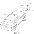
- a center line of a body of a to-be-calibrated automobile 200 is calibrated, and a projected center line 300 thereof is marked on the ground.
- an equidistant line 400 of a calibration distance that is perpendicular to the central projection line 300 is drawn.
- the round emitting hole 2108 of the laser-corner reflecting apparatus 20 is enabled to directly face a head of the to-be-calibrated automobile 200, and a first calibration line 1105 and a second calibration line 1106 of the base body 110 and the equidistant line 400 overlap.
- Left and right positions of the base body 110 are adjusted, so that the third calibration line 1107 and the projected center line 300 overlap, and a height of the laser-corner reflecting apparatus 20 is adjusted until a laser point can approximately irradiate a center of the on-board radar, that is, initial alignment of the laser-corner reflecting apparatus and the on-board radar is completed.
- the first calibration line 1105 and the second calibration line 1106 are kept to coincide with the equidistant line 400, and the third calibration line 1107 is kept to coincide with the projected center line 300.
- a horizontal adjustment member 113 of the base body 110 is adjusted to enable bubbles of the first horizontal bead 1140 and the second horizontal bead 1142 to be at central positions.
- the height of the laser-corner reflecting apparatus 20 on the bracket assembly 10 may be adjusted, thereby reflecting the radar wave emitted by the on-board radar in different heights, to calibrate an installation position and an installation angle of the on-board radar.
- the laser-corner reflecting apparatus 20 includes a laser 21 and a corner reflector 22.
- the corner reflector 22 is mounted to the laser 21, and the laser 21 emits a laser to align a position of the corner reflector 22 with that of the on-board radar. After the position of the corner reflector 22 is aligned with that of the on-board radar, the corner reflector 22 reflects the radar wave emitted by the on-board radar, so that the radar wave returns along an original path to calibrate the installation position and the installation angle of the on-board radar.
- the corner reflector 22 may be aligned with the on-board radar using the laser 21, and then the on-board radar is calibrated using the corner reflector 22, without the help of other calibration apparatuses, simplifying calibration operations of the on-board radar.
- the laser-corner reflecting apparatus 20 is mounted to the bracket assembly 10, and the laser-corner reflecting apparatus 20 may move relative to the bracket assembly 10 to adjust the height of the laser-corner reflecting apparatus 20, so that the on-board radar calibration device 100 may be adapted to heights of different vehicle types to calibrate on-board radars of different vehicle types.
- the fixed shaft 212 is inserted into the accommodating hole 1327, and the clamping portion 1322 clamps a structure of the fixed shaft 212, so that the laser-corner reflecting apparatus 20 may be conveniently and rapidly mounted to the holder 132 or detached from the holder 132.
- the locating pin 213 is inserted into the locating hole 1326, it can be ensured that a laser emitted from the round emitting hole 2108 is perpendicular to the vertical rod 12, so that the laser emitted from the round emitting hole 2108 is horizontally emitted after the base body 110 is horizontally adjusted, to align a position of the corner reflector 22 with that of the on-board radar.
- the height of the sliding assembly 13 may be adjusted by a large stroke, or the height of the sliding assembly 13 may be fine adjusted, so as to flexibly meet different use requirements.
- the third calibration line 1107 is disposed on the base body 110 to facilitate calibration of the bracket assembly 10 with a center line of the automobile body on a projected center line 300 on the ground.
- At least one of the first calibration line 1105 and the second calibration line 1106 is disposed on the base body 110 to facilitate calibration of the bracket assembly 10 with the equidistant line 400, to make preparation for accurate calibration on the laser-corner reflecting apparatus 20 carried by the bracket assembly 10.
- the central axis of the locating hole 1326 and the central axis of the accommodating hole 1327 are both parallel to the third calibration line 1107, and the central axis of the locating hole 1326, the central axis of the accommodating hole 1327, and the third calibration line 1107 are located in a same vertical plane.
Landscapes
- Engineering & Computer Science (AREA)
- Radar, Positioning & Navigation (AREA)
- Remote Sensing (AREA)
- Physics & Mathematics (AREA)
- Computer Networks & Wireless Communication (AREA)
- General Physics & Mathematics (AREA)
- Electromagnetism (AREA)
- Optical Radar Systems And Details Thereof (AREA)
Abstract
Description
- The application claims Chinese Patent No.
201810031836.6 - The present invention relates to the technical field of vehicle maintenance and device calibration, and in particular, to an on-board radar calibration device.
- In the field of advanced driver assistant systems (ADAS), an adaptive cruise control (ACC) system is a commonly used assistant function. A specific working principle of the adaptive cruise control system is measuring a distance from a front vehicle using an on-board radar, comparing a speed of the vehicle to a speed of the vehicle ahead, and controlling power systems such as an accelerator and a braking system of the vehicle, so that the vehicle is kept at a constant safety distance from the front vehicle. Therefore, a function of the on-board radar is of vital importance to implementation of the ACC function. In addition to measurement performance of the radar, an installation position and an installation angle thereof determine correctness and accuracy of final measurement data thereof. The foregoing installation position and installation angle change due to uncontrollable factors such as vibration and collision caused by use of the vehicle. Therefore, in the field of vehicle maintenance and device calibration, especially for calibration of the ACC function, calibration of the on-board radar is core content. At present, calibration of the on-board radar is mostly after-loading calibration. In other words, after a vehicle is delivered from a factory to a user in use for a period, the on-board radar is required to be calibrated due to an objective reason.
- During implementation of the present invention, an inventor finds that one calibration tool is mainly a single vehicle type calibration tool, that is, one calibration tool can be only used to calibrate an on-board radar of a single vehicle type. In addition, a calibration method excessively depends on software to calculate a deviation angle, and can be implemented through repeated calibration for a plurality of times, which is complex and inconvenient for use.
- In order to resolve the foregoing technical problems, embodiments of the present invention provide an on-board radar calibration device with simple calibration operations.
- In the embodiments of the present invention, the technical problems are resolved using the following technical solutions.
- An on-board radar calibration device includes a laser-corner reflecting apparatus, the laser-corner reflecting apparatus including a laser and a corner reflector, and the corner reflector being mounted to the laser. The laser is configured to emit a laser, so as to calibrate positions of the corner reflector and an on-board radar. The corner reflector is configured to reflect a radar wave emitted by the on-board radar, so that the radar wave returns along an original path, to calibrate an angle of mounting the on-board radar.
- Optionally, the laser includes a round emitting hole;
the corner reflector includes a corner reflecting plate, the corner reflecting plate being an isosceles right triangle plate, right-angle sides of the three corner reflecting plates being connected to each other, vertexes of vertex angles of the three corner reflecting plates overlapping at an intersection point, the vertex angles of the three corner reflecting plates being connected to the laser, and the round emitting hole being located at the intersection point. - Optionally, the on-board radar calibration device includes a bracket assembly, the laser-corner reflecting apparatus being mounted the bracket assembly, and the lase-corner reflecting apparatus may move relative to the bracket assembly, to adjust a height of the laser-corner reflecting apparatus.
- Optionally, the bracket assembly includes a base, a vertical rod, and a sliding assembly;
the vertical rod being disposed vertically, one end thereof being fixed to the base;
the sliding assembly being movably mounted to the vertical rod and sliding along the vertical rod; and
the laser-corner reflecting apparatus being mounted to the sliding assembly. - Optionally, the laser includes a laser body, the laser body including a fixed shaft and the round emitting hole, and the fixed shaft being perpendicular to the vertical rod; and
an accommodating hole is disposed on the sliding assembly, and the fixed shaft is accommodated in the accommodating hole. - Optionally, the laser body includes a locating pin, the fixed shaft being parallel to the locating pin; and
a locating hole is disposed on the sliding assembly, the locating pin being accommodated in the locating hole. - Optionally, the fixed shaft is cylindrical, one end thereof being fixedly connected to the laser body;
the locating pin is cylindrical, one end thereof being also fixedly connected to the laser body; and
a central axis of the fixed shaft, a central axis of the locating pin, and a central axis of the round emitting hole are located in a same vertical plane. - Optionally, a switch, a charging interface, and a charging indicator are disposed on the laser body;
the switch being configured to turn on or turn off the laser body;
the charging interface being configured to connect a power source so as to charge the laser body; and
the charging indicator being configured to indicate a charging state of the laser body. - Optionally, the sliding assembly includes a holder, the holder including a holder body, a clamping portion, a connecting rod, and a handle;
two clamping portions extend from the holder body, an accommodating hole is disposed between the two clamping portions, and there is a gap between the two clamping portions, the gap being in communication with the accommodating hole;
one end of the connecting rod penetrates through one of the clamping portions and is fixed to the another clamping portion, and the other end of the connecting rod is hinged on the handle; and
a cam block and a rotation shaft are disposed on the handle, one end that is of the connecting rod and that is away from the clamping portion is connected to the rotation shaft, two cam blocks are sleeved on both ends of the rotation shaft, and the two cam blocks may rotate relative to the rotation shaft to press against the clamping portion, so that the two clamping portions clamp the two fixed shaft. - Optionally, the holder includes a compressing block, the compressing block being sleeved on the connecting rod, and the compressing block being located between the clamping portion and the cam block.
- Optionally, the sliding assembly includes a clamping member, the clamping member being sleeved on the vertical rod and sliding along the vertical rod, and the clamping member clamping the vertical rod to fix the sliding assembly to a required position.
- Optionally, a rack is further disposed on the vertical rod, the gear rack being disposed vertically;
the sliding assembly includes a self-locking member, the self-locking member including a fine adjustment knob and an adjusting gear;
the fine adjustment knob is movably mounted to the clamping member, and the fine adjustment knob may rotate relative to the clamping member; and
the adjusting gear is sleeved on the fine adjustment knob, and the adjusting gear is meshed with the rack to fine adjust a height of the sliding assembly. - Optionally, the self-locking member includes a fixed rotation shaft, a pressing plate, and an elastic member;
both ends of the fixed rotation shaft being respectively fixedly mounted to the clamping member, and a central axis of the fixed rotation shaft being parallel to a rotation axis of the fine adjustment knob;
the pressing plate being sleeved on the fixed rotation shaft and the fine adjustment knob, the pressing plate rotating around the fixed rotation shaft to drive the fine adjustment knob to move relative to the clamping member, so that the gear is separated from the rack; and
the elastic member being compressed between the pressing plate and the clamping member, to provide recovery elasticity for the pressing plate, so that the adjusting gear compresses the rack. - Optionally, the pressing plate includes a pressing plate body and a mounting ear;
two mounting ears extending from the pressing plate body, and the pressing plate body being sleeved on the fixed rotation shaft; and
the two mounting ears being sleeved on the fine adjustment knob, and the adjusting gear being located between the two mounting ears. - Optionally, the clamping member includes a first clamping plate, a second clamping plate, and a locking knob;
the first clamping plate and the second clamping plate being respectively located at two opposite sides of the vertical rod and respectively abutting against the vertical rod; and
one end of the locking knob penetrating through the first clamping plate, and the locking knob being engaged with the first clamping plate through threads, and when the locking knob is rotated, the locking knob penetrating through one end of the first clamping plate and abutting against the vertical rod, so that the clamping member is fixed to the vertical rod. - Optionally, the clamping member includes a friction pad and a pad screw;
the friction pad being disposed between the first clamping plate and the vertical rod for increasing friction between the first clamping plate and the vertical rod; and
one end of the pad screw penetrating through the first clamping plate and abutting against the friction pad, and when the pad screw is rotated, a degree of contact between the friction pad and the vertical rod being adjusted, so as to adjust a magnitude of friction between the friction pad and the vertical rod. - Optionally, the base includes a base body, a horizontal adjustment member, and a gradienter;
one end of the vertical rod being fixedly mounted to the base body;
the horizontal adjustment member being mounted to the base body to adjust a horizontal angle of the base body; and
the gradienter being mounted to the base body for detecting whether the base body is horizontally disposed. - Optionally, the base includes a supporting member, one end of the supporting member being fixedly mounted to a lower surface of the base body, and there being at least one supporting member, where one intersection point formed through intersection of one supporting member and the lower surface, and two intersection points formed respectively through intersection of the two horizontal adjustment members and the lower surface are respectively located at three vertexes of an isosceles triangle.
- Optionally, there are three supporting members, the three supporting members being arranged orderly along a first straight line; and
the two horizontal adjustment members are arranged orderly along a second straight line, and the first straight line is parallel to the second straight line. - Optionally, the horizontal adjustment member includes a handle and a screw portion;
the handle being fixedly mounted to one end of the screw portion, and the handle being located over the base body to facilitate rotation of the horizontal adjustment member; and
the screw portion penetrating through the base body, the screw portion being engaged with the base body through threads, and the screw portion being vertically disposed. - Optionally, there are at least three horizontal adjustment members, where the three horizontal adjustment members respectively intersect the lower surface of the base body to form three intersection points, the three intersection points being respectively located at three vertexes of an isosceles triangle.
- Optionally, the gradienter is mounted to an upper surface of the base body, and the gradienter includes a first horizontal bead and a second horizontal bead, the first horizontal bead being perpendicular to the second horizontal bead.
- Optionally, a first calibration line, a second calibration line, and a third calibration line are disposed on the upper surface of the base body;
the first calibration line and the second calibration line being located on a same straight line; and
the third calibration line being perpendicular to the first calibration line and the second calibration line, and a straight line on which the third calibration line is located passing through an intersection point of the vertical rod and the base body. - Optionally, a first calibration line and a third calibration line are disposed on an upper surface of the base body;
the third calibration line being perpendicular to the first calibration line, and a straight line on which the third calibration line is located passing through an intersection point of the vertical rod and the base body. - Optionally, the third calibration line is parallel to a central axis of the accommodating hole, and the third calibration line and the central axis of the accommodating hole are located in a same vertical plane.
- Optionally, a height gauge is disposed for the vertical rod for measuring a moving distance or a height of the sliding assembly.
- In comparison to the prior art, in the on-board radar calibration device of the embodiments of the present invention, the corner reflector may be aligned with the on-board radar using the laser, and then the on-board radar may be calibrated using the corner reflector, without the help of other calibration apparatuses, simplifying calibration operations of the on-board radar.
- One or more embodiments are described by way of example with reference to the corresponding figures in the accompanying drawings, and the descriptions are not to be construed as limiting the embodiments. Elements in the accompanying drawings that have same reference numerals are represented as similar elements, and unless otherwise particularly stated, the figures in the accompanying drawings are not drawn to scale.
-
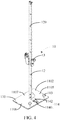
FIG. 1 is a three-dimensional diagram of an on-board radar calibration device according to an embodiment of the present invention; -
FIG. 2 is a three-dimensional diagram of a calibration device shown inFIG. 1 from another perspective; -
FIG. 3 is a partial enlarged diagram of a portion A inFIG. 2 ; -
FIG. 4 is a three-dimensional diagram of a calibration device shown inFIG. 1 from still another perspective; -
FIG. 5 is a three-dimensional diagram of a base of a calibration device shown inFIG. 1 ; -
FIG. 6 is a schematic assembly diagram of a sliding assembly and a vertical rod of a calibration device shown inFIG. 1 ; -
FIG. 7 is a schematic assembly diagram of a sliding assembly and a vertical rod of a calibration device shown inFIG. 1 from another perspective, a handle of the sliding assembly being cocked; -
FIG. 8 is a three-dimensional assembly diagram of a sliding assembly and a vertical rod of a calibration device shown inFIG. 1 from still another perspective, the handle being pressed down; -
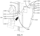
FIG. 9 is a partial exploded diagram of a sliding assembly of a calibration device shown inFIG. 1 ; -
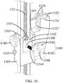
FIG. 10 is a partial exploded diagram of a sliding assembly of a calibration device shown inFIG. 1 from another perspective; -
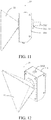
FIG. 11 to FIG. 14 are respective three-dimensional diagrams of a laser-corner reflecting apparatus of a calibration device shown inFIG. 1 from different angles; and -
FIG. 15 to FIG. 17 are respective schematic diagrams of different steps in which an on-board radar is calibrated using a calibration device according to an embodiment of the present invention. - One or more embodiments are described by way of example with reference to the corresponding figures in the accompanying drawings, and the descriptions are not to be construed as limiting the embodiments. Elements in the accompanying drawings that have same reference numerals are represented as similar elements, and unless otherwise particularly stated, the figures in the accompanying drawings are not drawn to scale. The terms "vertical", "horizontal", "left", "right", "inside", "outside", and similar expressions, as used in this specification, are for the purpose of description only.
- Unless otherwise defined, all technical and scientific terms used herein have the same meaning as commonly understood by one of ordinary skill in the art to which the present invention belongs. The terms used in the specification of the present invention are merely used for describing specific embodiments, and are not intended to limit the present invention. As used herein, the term "and/or" includes any and all combinations of one or more related items listed.
- In addition, the technical features provided in different embodiments of the present invention to be described below may be combined with each other as long as no conflict occurs.
- Referring to
FIG. 1 , an on-boardradar calibration device 100 according to an embodiment of the present invention includes abracket assembly 10 and a laser-corner reflecting apparatus 20. The laser-corner reflecting apparatus 20 is mounted to thebracket assembly 10, and the laser-corner reflecting apparatus 20 may move relative to thebracket assembly 10 along a vertical direction, to adjust a height of the laser-corner reflecting apparatus 20. - Referring to both
FIG. 2 andFIG. 3 , thebracket assembly 10 includes abase 11, avertical rod 12, and a slidingassembly 13. Thevertical rod 12 is vertically disposed, one end thereof being fixedly mounted to thebase 11. The slidingassembly 13 is movably installed at thevertical rod 12, and the slidingassembly 13 may slide along thevertical rod 12. - The
base 11 includes abase body 110, a supportingmember 112, ahorizontal adjustment member 113, and agradienter 114. - The
base body 110 is a rectangular plate and may be made of a metal material with a large mass, so that thebracket assembly 10 has a low center of gravity to stably support the laser-corner reflecting apparatus 20. Thebase body 110 includes anupper surface 1102 and alower surface 1104. - Referring to both
FIG. 4 andFIG. 5 , afirst calibration line 1105, asecond calibration line 1106, and athird calibration line 1107 are disposed on theupper surface 1102. Thefirst calibration line 1105 and thesecond calibration line 1106 are located on a same straight line. Thethird calibration line 1107 is perpendicular to thefirst calibration line 1105 and thesecond calibration line 1106. It may be understood that, in some other embodiments, either or both of thefirst calibration line 1105 and thesecond calibration line 1106 may be omitted, that is, only either of thefirst calibration line 1105 or thesecond calibration line 1106 is disposed on theupper surface 1102, or neither of thefirst calibration line 1105 nor thesecond calibration line 1106 is disposed. - Definitely, a fourth calibration line (not shown in the figure) may further be disposed on the
upper surface 1102, the fourth calibration line and thethird calibration line 1107 being located on a same straight line, which is not limited thereto. - The supporting
member 112 is disposed on thelower surface 1104, and the supportingmember 112 is substantially columnar and disposed along a vertical direction. One end of the supportingmember 112 is fixedly mounted to thelower surface 1104. Three supportingmembers 112 are arranged orderly along a first straight line. The first straight line is parallel to thefirst calibration line 1105 and thesecond calibration line 1106. - A
horizontal adjustment member 113 includes ahandle 1132 and ascrew portion 1134. Thehandle 1132 is fixedly mounted to one end of thescrew portion 1134. Thescrew portion 1134 penetrates through theupper surface 1102 and thelower surface 1104. Thescrew portion 1134 is engaged with thebase body 110 through threads, and thescrew portion 1134 is vertically disposed. Thehandle 1132 is located over theupper surface 1102 to facilitate rotation of thehorizontal adjustment member 113, so that thehorizontal adjustment member 113 moves relative to thebase body 110 along a vertical direction, so as to adjust depression and elevation angles of thebase body 110. Twohorizontal adjustment members 113 are arranged orderly along a second straight line. The first straight line is parallel to the second straight line. One intersection point formed through intersection of one of the supportingmembers 112 and thelower surface 1104, and two intersection points formed respectively through intersection of the twohorizontal adjustment members 113 and thelower surface 1104 are respectively located at three vertexes of an isosceles triangle. - It may be understood that, in some other embodiments, a quantity of the supporting
members 112 may be increased or decreased according to actual requirements, but there must be at least one supporting member. In addition, one intersection point formed through intersection of one of the supportingmembers 112 and thelower surface 1104, and two intersection points formed respectively through intersection of the twohorizontal adjustment members 113 and thelower surface 1104 are respectively located at the three vertexes of the isosceles triangle. - It may be understood that, in some other embodiments, the
horizontal adjustment member 113 may be other structures as long as the structures can adjust depression and elevation angles of thebase body 110. There may also be at least threehorizontal adjustment members 113, but the supportingmember 112 is omitted, and the threehorizontal adjustment members 113 respectively intersect thelower surface 1104 of thebase body 110 to form three intersection points, the three intersection points being respectively located at the three vertexes of the isosceles triangle. - A
gradienter 114 is mounted to theupper surface 1102 for detecting whether thebase body 110 is horizontally disposed. Thegradienter 114 includes a firsthorizontal bead 1140 and a secondhorizontal bead 1142, the firsthorizontal bead 1140 being perpendicular to the secondhorizontal bead 1142. It may be understood that, in some other embodiments, thegradienter 114 may also be other structures as long as the structures can be used to detect whether thebase body 110 is horizontally disposed. - One end of the
vertical rod 12 is fixedly mounted to theupper surface 1102, and thevertical rod 12 is perpendicular to thebase body 110. A straight line on which thethird calibration line 1107 is located passes through an intersection point of thevertical rod 12 and thebase body 110. Aheight gauge 120 is disposed for thevertical rod 12 for measuring a moving distance or a height of the slidingassembly 13. Arack 122 is further disposed on thevertical rod 12, therack 122 being disposed along a vertical direction (seeFIG. 9 ). - Referring to
FIG. 6 , the slidingassembly 13 is made of an elastic material, for example, a metal material or a plastic material, etc. The slidingassembly 13 includes a clampingmember 130, aholder 132, and a self-lockingmember 134. The clampingmember 130 is sleeved on thevertical rod 12, may slide along thevertical rod 12, and may clamp thevertical rod 12 to fix the slidingassembly 13 to a required position. Theholder 132 is fixedly mounted to the clampingmember 130 for supporting the laser-corner reflecting apparatus 20. The self-lockingmember 134 is mounted to the clampingmember 130 for switching between large-stroke adjustment of a height of the slidingassembly 13 and fine adjustment of the height of the slidingassembly 13. - Referring to
FIG. 7 , the clampingmember 130 includes afirst clamping plate 1301, asecond clamping plate 1302, alocking knob 1303, afriction pad 1304, and apad screw 1305. - The
first clamping plate 1301 is connected to thesecond clamping plate 1302, and thefirst clamping plate 1301 and thesecond clamping plate 1302 are respectively located at two opposite sides of thevertical rod 12 and respectively abut against thevertical rod 12. - One end of the
locking knob 1303 penetrates through thefirst clamping plate 1301, and thelocking knob 1303 is engaged with thefirst clamping plate 1301 through threads. The lockingknob 1303 is rotated to enable thelocking knob 1303 to penetrate through one end of thefirst clamping plate 1301 and abut against thevertical rod 12, so that the clampingmember 130 is fixed to thevertical rod 12. - The
friction pad 1304 is disposed between thefirst clamping plate 1301 and thevertical rod 12 for increasing friction between thefirst clamping plate 1301 and thevertical rod 12. - There are two
pad screws 1305, and one end of each of the pad screws 1305 penetrates through thefirst clamping plate 1301 and abuts against thefriction pad 1304. Thepad screw 1305 is rotated to adjust a degree of contact between thefriction pad 1304 and thevertical rod 12, so as to adjust a magnitude of friction between thefriction pad 1304 and thevertical rod 12. In this embodiment, a magnitude of the friction between thefriction pad 1304 and thevertical rod 12 may be adjusted as required, so that the slidingassembly 13 may smoothly slide relative to thevertical rod 12. It may be understood that, in some other embodiments, thefriction pad 1304 and thepad screw 1305 may be omitted. - With reference to
FIG. 7 and referring to bothFIG. 8 andFIG. 9 , theholder 132 includes aholder body 1321, a clampingportion 1322, a connectingrod 1323, acompressing block 1324, and ahandle 1325. - The
holder body 1321 is fixedly connected to thesecond clamping plate 1302, and alocating hole 1326 is disposed on theholder body 1321. - Two clamping
portions 1322 extend from theholder body 1321, anaccommodating hole 1327 is disposed between the two clampingportions 1322, and there is a gap between the two clampingportions 1322, the gap being in communication with theaccommodating hole 1327. The locatinghole 1326 and theaccommodating hole 1327 are both cylindric and horizontally disposed. A central axis of thelocating hole 1326 and a central axis of theaccommodating hole 1327 are both parallel to thethird calibration line 1107, and the central axis of thelocating hole 1326, the central axis of theaccommodating hole 1327, and thethird calibration line 1107 are located in a same vertical plane. - One end of the connecting
rod 1323 penetrates through one of the clampingportions 1322 and is fixed to theother clamping portion 1322, and the other end of the connectingrod 1323 is hinged on thehandle 1325. Thecompressing block 1324 is sleeved on the connectingrod 1323, and thecompressing block 1324 is located between the clampingportion 1322 and thehandle 1325. Thecompressing block 1324 may be made of a metal material, for example, copper. - A
cam block 1328 and arotation shaft 1329 are disposed for thehandle 1325. One end that is of the connectingrod 1323 and that is away from the clampingportion 1322 is connected to a central portion of therotation shaft 1329. Twocam blocks 1328 are sleeved on both ends of therotation shaft 1329, the twocam blocks 1328 may rotate relative to therotation shaft 1329, and the twocam blocks 1328 are parallel to each other and are spaced apart by a preset distance. - The
handle 1325 is pressed to enable the twocam blocks 1328 to rotate around therotation shaft 1329. During rotation of the cam blocks 1328, the cam blocks 1328 compress thecompressing block 1324 to enable the two clampingportions 1322 to move toward each other, and theaccommodating hole 1327 is narrowed to clamp the laser-corner reflecting apparatus 20 (seeFIG. 8 ). Thehandle 1325 is cocked to enable the twocam blocks 1328 to rotate oppositely around therotation shaft 1329, the cam blocks 1328 release squeezing of thecompressing block 1324, the two clampingportions 1322 move oppositely, and theaccommodating hole 1327 is enlarged to take the laser-corner reflecting apparatus 20 down from the holder 132 (seeFIG. 7 ). With theholder 132 of this embodiment, the laser-corner reflecting apparatus 20 may be conveniently and rapidly installed or dismantled. In addition, thecompressing block 1324 is disposed between the clampingportion 1322 and thehandle 1325 for increasing a degree of compressing the clampingportion 1322 by the twocam blocks 1328, so that the two clampingportions 1322 may more firmly clamp the laser-corner reflecting apparatus 20. - It may be understood that, in some other embodiments, the
compressing block 1324 may be omitted, and the twocam blocks 1328 may directly compress theclamping portion 1322. - Referring to both
FIG. 9 andFIG. 10 , the self-lockingmember 134 includes afine adjustment knob 1340, anadjusting gear 1341, afixed rotation shaft 1342, apressing plate 1343, and anelastic member 1344. - One end of the
fine adjustment knob 1340 is movably mounted to thesecond clamping plate 1302 after penetrating through thefirst clamping plate 1301. Thefine adjustment knob 1340 may rotate relative to thefirst clamping plate 1301 and thesecond clamping plate 1302, and may move in parallel relative to thefirst clamping plate 1301 and thesecond clamping plate 1302. - The
adjusting gear 1341 is sleeved on thefine adjustment knob 1340 and located between thefirst clamping plate 1301 and thesecond clamping plate 1302, and theadjusting gear 1341 is meshed with therack 122. - Both ends of the fixed
rotation shaft 1342 are respectively fixedly mounted to thefirst clamping plate 1301 and thesecond clamping plate 1302, and a central axis of the fixedrotation shaft 1342 is parallel to a rotation axis of thefine adjustment knob 1340. - The
pressing plate 1343 includes apressing plate body 1345 and a mountingear 1346. Afirst mounting hole 1348 is disposed for thepressing plate body 1345. Two mountingears 1346 extend from thepressing plate body 1345, and the two mountingears 1346 are spaced apart by a preset distance and disposed in parallel. Thepressing plate body 1345 is sleeved on the fixedrotation shaft 1342, the two mountingears 1346 are sleeved on thefine adjustment knob 1340, and theadjusting gear 1341 is located between the two mountingears 1346. - The
elastic member 1344 is compressed between thepressing plate 1343 and the clampingmember 130. Both ends of theelastic member 1344 are respectively accommodated in afirst mounting hole 1348 of thepressing plate 1343 and asecond mounting hole 1308 of the clampingmember 130. In this embodiment, theelastic member 1344 is a compression spring for providing recovery elasticity. It may be understood that, in some other embodiments, theelastic member 1344 may be a spring piece or other elastic members that can provide the recovery elasticity. - The
pressing plate 1343 is pressed, so that thepressing plate 1343 rotates around the fixedrotation shaft 1342, theelastic member 1344 is further compressed, and the mountingear 1346 drives thefine adjustment knob 1340 to move relative to thefirst clamping plate 1301 and thesecond clamping plate 1302, so that thegear 1341 is separated from therack 122. In this case, the lockingknob 1303 is rotated to enable thelocking knob 1303 to be not in contact with thevertical rod 12, and the slidingassembly 13 may move relative to thevertical rod 12 by a large stroke. Thepressing plate 1343 is loosened, and theelastic member 1344 generates the recovery elasticity to push thepressing plate 1343 to rotate reversely around the fixedrotation shaft 1342, so that theadjusting gear 1341 is meshed with therack 122. In this case, theelastic member 1344 provides elasticity to enable theadjusting gear 1341 to press against therack 122. Thefine adjustment knob 1340 is rotated, and theadjusting gear 1341 rotates and drives therack 122 to move, so that a position of the slidingassembly 13 relative to thevertical rod 12 may be fine adjusted. - With the self-locking
member 134, a height of the slidingassembly 13 may be adjusted by a large stroke, or a height of the slidingassembly 13 may be fine adjusted. It may be understood that, in some other embodiments, the fixedrotation shaft 1342, thepressing plate 1343, and theelastic member 1344 may be omitted, theadjusting gear 1341 is meshed with therack 122, and the self-lockingmember 134 may only fine adjust the height of the slidingassembly 13. Alternatively, the self-lockingmember 134 and therack 122 may be omitted, and the height of the slidingassembly 13 may be adjusted only by a large stroke. - Referring to
FIG. 11 , the laser-corner reflecting apparatus 20 includes alaser 21 and acorner reflector 22. Thelaser 21 is configured to emit a laser, so as to align a position of thecorner reflector 22 with that of an on-board radar. Thecorner reflector 22 is mounted to thelaser 21 for reflecting a radar wave emitted from any direction, so that the radar wave returns along an original path, to calibrate an installation position and an installation angle of the on-board radar. - The
laser 21 includes alaser body 210, a fixedshaft 212, and a locatingpin 213. Thelaser body 210 is configured to emit a laser. One end of the fixedshaft 212 is fixedly connected to thelaser body 210, and one end of the locatingpin 213 is also fixedly connected to thelaser body 210. Both the fixedshaft 212 and the locatingpin 213 are cylindric, and the fixedshaft 212 and the locatingpin 213 are parallel to each other and perpendicular to thevertical rod 12. Both the fixedshaft 212 and the locatingpin 213 are parallel to an emitting direction of the laser. - Still referring to
FIG. 12 andFIG. 14 , aswitch 2102, a charginginterface 2104, and acharging indicator 2106 are disposed on thelaser body 210. Theswitch 2102 is configured to turn on or turn off thelaser body 210, the charginginterface 2104 is configured to connect a power source to charge thelaser body 210, and thecharging indicator 2106 is configured to indicate a charging state of thelaser body 210, for example, red light indicates charging, and green light indicates charging completed. Around emitting hole 2108 is further disposed on thelaser body 210 to emit a laser. A central axis of the fixedshaft 212, a central axis of the locatingpin 213, and a central axis of theround emitting hole 2108 are located in a same vertical plane. - The
corner reflector 22 includes acorner reflecting plate 220, there are threecorner reflecting plates 220, and each of thecorner reflecting plates 220 is an isosceles right triangle plate. Right-angle sides of the threecorner reflecting plates 220 are connected to each other, vertexes of vertex angles of the threecorner reflecting plates 220 overlap at an intersection point, and the vertex angles of the threecorner reflecting plates 220 are connected to thelaser body 210, theround emitting hole 2108 being located at the intersection point. Each of thecorner reflecting plates 220 may be made of a metal material to reflect a radar wave. Alternatively, each of thecorner reflecting plate 220 has a radar wave reflection layer, the radar wave reflection layer being made of a radar wave reflective material to reflect the radar wave. - Referring to both
FIG. 8 andFIG. 11 , when the laser-corner reflecting apparatus 20 is mounted to theholder 132, the fixedshaft 212 is inserted into theaccommodating hole 1327, and the locatingpin 213 is inserted into thelocating hole 1326. Thehandle 1325 is pressed to enable the twocam blocks 1328 to press against thecompressing block 1324, so that the two clampingportions 1322 move toward each other, and theaccommodating hole 1327 is narrowed to clamp the fixedshaft 212, so that the laser-corner reflecting apparatus 20 may be conveniently fixed to theholder 132. - When the laser-
corner reflecting apparatus 20 is detached from theholder 132, thehandle 1325 is cocked, the twocam blocks 1328 release squeezing of thecompressing block 1324, and the two clampingportions 1322 move oppositely. The fixedshaft 212 is loosened to take the laser-corner reflecting apparatus 20 down from theholder 132. - When the laser-
corner reflecting apparatus 20 is mounted to theholder 132 with cooperation of the locatingpin 213 and thelocating hole 1326, it is ensured that an emitting direction of laser emitted by the laser-corner reflecting apparatus 20 is perpendicular to thevertical rod 12, so as to ensure the laser emitted by the laser-corner reflecting apparatus 20 is horizontally emitted after thebase body 110 is horizontally adjusted, to ensure that the on-board radar is accurately calibrated. - Referring to
FIG. 15 , in a first step of calibrating the on-board radar, a center line of a body of a to-be-calibrated automobile 200 is calibrated, and a projectedcenter line 300 thereof is marked on the ground. According to a vehicle calibration requirement, anequidistant line 400 of a calibration distance that is perpendicular to thecentral projection line 300 is drawn. - Referring to
FIG. 4 ,FIG. 16 , andFIG. 17 together, in a second step of calibrating the on-board radar, theround emitting hole 2108 of the laser-corner reflecting apparatus 20 is enabled to directly face a head of the to-be-calibrated automobile 200, and afirst calibration line 1105 and asecond calibration line 1106 of thebase body 110 and theequidistant line 400 overlap. Left and right positions of thebase body 110 are adjusted, so that thethird calibration line 1107 and the projectedcenter line 300 overlap, and a height of the laser-corner reflecting apparatus 20 is adjusted until a laser point can approximately irradiate a center of the on-board radar, that is, initial alignment of the laser-corner reflecting apparatus and the on-board radar is completed. - In a third step of calibrating the on-board radar, the
first calibration line 1105 and thesecond calibration line 1106 are kept to coincide with theequidistant line 400, and thethird calibration line 1107 is kept to coincide with the projectedcenter line 300. Ahorizontal adjustment member 113 of thebase body 110 is adjusted to enable bubbles of the firsthorizontal bead 1140 and the secondhorizontal bead 1142 to be at central positions. In addition, a position of the laser point on the on-board radar is noticed, and the height and a horizontal position of the laser-corner reflecting apparatus 20 are adjusted through cooperation, until the laser point is also illuminated at a center of the on-board radar when the bubbles of the firsthorizontal bead 1140 and the secondhorizontal bead 1142 are located at the center of the horizontal bead. Therefore, accurate alignment of the laser-corner reflecting apparatus 20 and the on-board radar is completed. - In a fourth step of calibrating the on-board radar, according to an actual calibration requirement, when the
bracket assembly 10 is kept motionless, the height of the laser-corner reflecting apparatus 20 on thebracket assembly 10 may be adjusted, thereby reflecting the radar wave emitted by the on-board radar in different heights, to calibrate an installation position and an installation angle of the on-board radar. - In the embodiment of the present invention, the laser-
corner reflecting apparatus 20 includes alaser 21 and acorner reflector 22. Thecorner reflector 22 is mounted to thelaser 21, and thelaser 21 emits a laser to align a position of thecorner reflector 22 with that of the on-board radar. After the position of thecorner reflector 22 is aligned with that of the on-board radar, thecorner reflector 22 reflects the radar wave emitted by the on-board radar, so that the radar wave returns along an original path to calibrate the installation position and the installation angle of the on-board radar. Thecorner reflector 22 may be aligned with the on-board radar using thelaser 21, and then the on-board radar is calibrated using thecorner reflector 22, without the help of other calibration apparatuses, simplifying calibration operations of the on-board radar. - In addition, the laser-
corner reflecting apparatus 20 is mounted to thebracket assembly 10, and the laser-corner reflecting apparatus 20 may move relative to thebracket assembly 10 to adjust the height of the laser-corner reflecting apparatus 20, so that the on-boardradar calibration device 100 may be adapted to heights of different vehicle types to calibrate on-board radars of different vehicle types. - In addition, the fixed
shaft 212 is inserted into theaccommodating hole 1327, and theclamping portion 1322 clamps a structure of the fixedshaft 212, so that the laser-corner reflecting apparatus 20 may be conveniently and rapidly mounted to theholder 132 or detached from theholder 132. What's more, when the locatingpin 213 is inserted into thelocating hole 1326, it can be ensured that a laser emitted from theround emitting hole 2108 is perpendicular to thevertical rod 12, so that the laser emitted from theround emitting hole 2108 is horizontally emitted after thebase body 110 is horizontally adjusted, to align a position of thecorner reflector 22 with that of the on-board radar. - Furthermore, with the self-locking
member 134, the height of the slidingassembly 13 may be adjusted by a large stroke, or the height of the slidingassembly 13 may be fine adjusted, so as to flexibly meet different use requirements. - Finally, the
third calibration line 1107 is disposed on thebase body 110 to facilitate calibration of thebracket assembly 10 with a center line of the automobile body on a projectedcenter line 300 on the ground. At least one of thefirst calibration line 1105 and thesecond calibration line 1106 is disposed on thebase body 110 to facilitate calibration of thebracket assembly 10 with theequidistant line 400, to make preparation for accurate calibration on the laser-corner reflecting apparatus 20 carried by thebracket assembly 10. In addition, the central axis of thelocating hole 1326 and the central axis of theaccommodating hole 1327 are both parallel to thethird calibration line 1107, and the central axis of thelocating hole 1326, the central axis of theaccommodating hole 1327, and thethird calibration line 1107 are located in a same vertical plane. When thethird calibration line 1107 is aligned with the projectedcenter line 300, the laser-corner reflecting apparatus 20 may be easily aligned with the center line of the to-be-calibrated automobile 200. - It should be finally noted that the above embodiments are merely intended for describing the technical solutions of the present invention rather than limiting the present invention. Based on the idea of the present invention, the technical features in the foregoing embodiments or different embodiments may be combined, the steps may be implemented in any order, and many other changes in the different aspects of the present invention as described above may exist. For brevity, such changes are not provided in the detailed descriptions. Although the present invention is described in detail with reference to the foregoing embodiments, those of ordinary skill in the art should understand that they can still make modifications to the technical solutions described in the foregoing embodiments or make equivalent substitutions to some technical features thereof, without departing from scope of the technical solutions of the embodiments of the present invention.
Claims (26)
- An on-board radar calibration device (100), comprising:a laser-corner reflecting apparatus (20), the laser-corner reflecting apparatus (20) comprising a laser (21) and a corner reflector (22), and the corner reflector (22) being mounted to the laser (21);the laser (21) being configured to emit a laser, so as to align a position of the corner reflector (22) with that of the on-board radar; andthe corner reflector (22) being configured to reflect a radar wave emitted by the on-board radar, so that the radar wave returns along an original path, to calibrate an installation angle of the on-board radar.
- The calibration device (100) according to claim 1, wherein the laser (21) comprises a round emitting hole (2108);
the corner reflector (22) comprises a corner reflecting plate (220), the corner reflecting plate (220) being an isosceles right triangle plate, right-angle sides of the three corner reflecting plates (220) being connected to each other, vertexes of vertex angles of the three corner reflecting plates (220) overlap at an intersection point, the vertex angles of the three corner reflecting plates (220) being connected to the laser (21), and the round emitting hole (2108) being located at the intersection point. - The calibration device (100) according to claim 2, comprising:
a bracket assembly (10), the laser-corner reflecting apparatus (20) being mounted to the bracket assembly (10), and the laser-corner reflecting apparatus (20) being movable relative to the bracket assembly (10), to adjust a height of the laser-corner reflecting apparatus (20). - The calibration device (100) according to claim 3, wherein the bracket assembly (10) comprises a base (11), a vertical rod (12), and a sliding assembly (13);
the vertical rod (12) being disposed vertically, and one end thereof being mounted to the base (11);
the sliding assembly (13) being movably mounted to the vertical rod (12) and movable along the vertical rod (12); and
the laser-corner reflecting apparatus (20) being mounted to the sliding assembly (13). - The calibration device (100) according to claim 4, wherein the laser (21) comprises a laser body (210), the laser body (210) comprising a fixed shaft (212) and the round emitting hole (2108), and the fixed shaft (212) being perpendicular to the vertical rod (12); and
an accommodating hole (1327) is disposed on the sliding assembly (13), and the fixed shaft (212) is accommodated in the accommodating hole (1327). - The calibration device (100) according to claim 5, wherein the laser body (210) comprises a locating pin (213), the fixed shaft (212) being parallel to the locating pin (213); and
wherein a locating hole (1326) is disposed on the sliding assembly (13), and the locating pin (213) is accommodated in the locating hole (1326). - The calibration device (100) according to claim 6, wherein the fixed shaft (212) is cylindrical, one end thereof being fixedly connected to the laser body (210);
wherein the locating pin (213) is cylindrical, one end thereof being also fixedly connected to the laser body (210); and
wherein a central axis of the fixed shaft (212), a central axis of the locating pin (213), and a central axis of the round emitting hole (2108) are located in a same vertical plane. - The calibration device (100) according to any of claims 5 to 7, wherein a switch (2102), a charging interface (2104), and a charging indicator (2106) are disposed on the laser body (210);
the switch (2102) being configured to turn on or turn off the laser body (210);
the charging interface (2104) being configured to connect a power supply to charge the laser body (210); and
the charging indicator (2106) being configured to indicate a charging state of the laser body (210). - The calibration device (100) according to any of claims 5 to 8, wherein the sliding assembly (13) comprises a holder (132), the holder (132) comprising a holder body (1321), a clamping portion (1322), a connecting rod (1323), and a handle (1325);
wherein two clamping portions (1322) extend from the holder body (1321), an accommodating hole (1327) is disposed between the two clamping portions (1322), and there is a gap between the two clamping portions (1322), the gap being in communication with the accommodating hole (1327);
wherein one end of the connecting rod (1323) penetrates through one of the clamping portions (1322) and is fixed to the other clamping portion (1322), and the other end of the connecting rod (1323) is hinged on the handle (1325); and
wherein a cam block (1328) and a rotation shaft (1329) are disposed on the handle (1325), one end that is of the connecting rod (1323) and that is away from the clamping portion (1322) is connected to the rotation shaft (1329), two cam blocks (1328) are sleeved on both ends of the rotation shaft (1329), and the two cam blocks (1328) are rotatable relative to the rotation shaft (1329), to press against the clamping portion (1322), so that the two clamping portions (1322) clamp the fixed shaft (212). - The calibration device (100) according to claim 9, wherein the holder (132) comprises a compressing block (1324), the compressing block (1324) being sleeved on the connecting rod (1323), and the compressing block (1324) being located between the clamping portion (1322) and the cam block (1328).
- The calibration device (100) according to any of claims 4 to 10, wherein the sliding assembly (13) comprises a clamping member (130), the clamping member (130) being sleeved on the vertical rod (12) and being slidable along the vertical rod (12), and the clamping member (130) clamping the vertical rod (12) to fix the sliding assembly (13) to a required position.
- The calibration device (100) according to claim 11, wherein a rack (122) is further disposed on the vertical rod (12), the rack (122) being disposed vertically;
wherein the sliding assembly (13) comprises a self-locking member (134), the self-locking member (134) comprising a fine adjustment knob (1340) and an adjusting gear (1341);
wherein the fine adjustment knob (1340) is movably mounted to the clamping member (130), and the fine adjustment knob (1340) is rotatable relative to the clamping member (130); and
wherein the adjusting gear (1341) is sleeved on the fine adjustment knob (1340), and the adjusting gear (1341) is meshed with the rack (122) to fine adjust a height of the sliding assembly (13). - The calibration device (100) according to claim 12, wherein the self-locking member (134) comprises a fixed rotation shaft (1342), a pressing plate (1343), and an elastic member (1344);
both ends of the fixed rotation shaft (1342) being respectively fixed to the clamping member (130), and a central axis of the fixed rotation shaft (1342) being parallel to a rotation axis of the fine adjustment knob (1340);
the pressing plate (1343) being sleeved on the fixed rotation shaft (1342) and the fine adjustment knob (1340), and the pressing plate (1343) being configured to rotate around the fixed rotation shaft (1342) to drive the fine adjustment knob (1340) to move relative to the clamping member (130), so that the gear (1341) is separated from the rack (122); and
wherein the elastic member (1344) is compressed between the pressing plate (1343) and the clamping member (130), to provide recovery elasticity for the pressing plate (1343), so that the adjusting gear (1341) compresses the rack (122). - The calibration device (100) according to claim 13, wherein the pressing plate (1343) comprises a pressing plate body (1345) and a mounting ear (1346);
two mounting ears (1346) extending from the pressing plate body (1345), and the pressing plate body (1345) being sleeved on the fixed rotation shaft (1342); and
the two mounting ears (1346) being sleeved on the fine adjustment knob (1340), and the adjusting gear (1341) being located between the two mounting ears (1346). - The calibration device (100) according to claim 11, wherein the clamping member (130) comprises a first clamping plate (1301), a second clamping plate (1302), and a locking knob (1303);
the first clamping plate (1301) and the second clamping plate (1302) being respectively located at two opposite sides of the vertical rod (12) and respectively abutting against the vertical rod (12); and
one end of the locking knob (1303) penetrating through the first clamping plate (1301), and the locking knob (1303) being engaged with the first clamping plate (1301) through threads, and when the locking knob (1303) is rotated, the locking knob (1303) being configured to penetrate through one end of the first clamping plate (1301) and abutting against the vertical rod (12), so that the clamping member (130) is fixed to the vertical rod (12). - The calibration device (100) according to claim 15, wherein the clamping member (130) comprises a friction pad (1304) and a pad screw (1305);
the friction pad (1304) being disposed between the first clamping plate (1301) and the vertical rod (12) for increasing friction between the first clamping plate (1301) and the vertical rod (12); and
one end of the pad screw (1305) penetrating through the first clamping plate (1301) and abutting against the friction pad (1304), and when the pad screw (1305) is rotated, a degree of contact between the friction pad (1304) and the vertical rod (12) being adjusted to adjust a magnitude of friction between the friction pad (1304) and the vertical rod (12). - The calibration device (100) according to any of claims 5 to 15, wherein the base (11) comprises a base body (110), a horizontal adjustment member (113), and a gradienter (114);
one end of the vertical rod (12) being fixedly mounted to the base body (110);
the horizontal adjustment member (113) being mounted to the base body (110) to adjust a horizontal angle of the base body (110); and
the gradienter (114) being mounted to the base body (110) for detecting whether the base body (110) is horizontally disposed. - The calibration device (100) according to claim 17, wherein the base (11) comprises a supporting member (112), one end of the supporting member (112) being fixedly mounted to a lower surface (1104) of the base body (110), and there being at least one supporting member (112), wherein one intersection point formed through intersection of one supporting member (112) and the lower surface (1104) and two intersection points formed respectively through intersection of the two horizontal adjustment members (113) and the lower surface (1104) are respectively located at three vertexes of an isosceles triangle.
- The calibration device (100) according to claim 18, wherein there are three supporting members (112), the three supporting members (112) being arranged orderly along a first straight line; and
the two horizontal adjustment members (113) are arranged orderly along a second straight line, the first straight line being parallel to the second straight line. - The calibration device (100) according to any of claims 17 to 19, wherein the horizontal adjustment member (113) comprises a handle (1132) and a screw portion (1134);
the handle (1132) being fixedly mounted to one end of the screw portion (1134), and the handle (1132) being located over the base body (110) to facilitate rotation of the horizontal adjustment member (113); and
the screw portion (1134) penetrating through the base body (110), the screw portion (1134) being engaged with the base body (110) through threads, and the screw portion (1134) being vertically disposed. - The calibration device (100) according to claim 17, wherein there are at least three horizontal adjustment members (113), and the three horizontal adjustment members (113) respectively intersect a lower surface (1104) of the base body (110) to form three intersection points, the three intersection points being respectively located at three vertexes of an isosceles triangle.
- The calibration device (100) according to any of claims 17 to 21, wherein the gradienter (114) is mounted to an upper surface (1102) of the base body (110), and the gradienter (114) comprises a first horizontal bead (1140) and a second horizontal bead (1142), the first horizontal bead (1140) being perpendicular to the second horizontal bead (1142).
- The calibration device (100) according to any of claims 17 to 22, wherein a first calibration line (1105), a second calibration line (1106), and a third calibration line (1107) are disposed on the upper surface (1102) of the base body (110);
the first calibration line (1105) and the second calibration line (1106) being located on a same straight line; and
the third calibration line (1107) being perpendicular to the first calibration line (1105) and the second calibration line (1106), and a straight line on which the third calibration line (1107) is located passing through an intersection point of the vertical rod (12) and the base body (110). - The calibration device (100) according to any of claims 17 to 22, wherein the first calibration line (1105) and the third calibration line (1107) are disposed on the upper surface (1102) of the base body (110); and
wherein the third calibration line (1107) is perpendicular to the first calibration line (1105), and a straight line on which the third calibration line (1107) is located passes through an intersection point of the vertical rod (12) and the base body (110). - The calibration device (100) according to claim 23 or 24, wherein the third calibration line (1107) is parallel to a central axis of the accommodating hole (1327), and the third calibration line (1107) and the central axis of the accommodating hole (1327) are located in a same vertical plane.
- The calibration device (100) according to any of claims 4 to 25, wherein a height gauge (120) is disposed for the vertical rod (12) for measuring a moving distance or a height of the sliding assembly (13).
Applications Claiming Priority (2)
| Application Number | Priority Date | Filing Date | Title |
|---|---|---|---|
| CN201810031836.6A CN107966690B (en) | 2018-01-12 | 2018-01-12 | Vehicle-mounted radar calibration equipment |
| PCT/CN2019/070776 WO2019137352A1 (en) | 2018-01-12 | 2019-01-08 | On-board radar calibration apparatus |
Publications (3)
| Publication Number | Publication Date |
|---|---|
| EP3734319A1 true EP3734319A1 (en) | 2020-11-04 |
| EP3734319A4 EP3734319A4 (en) | 2021-02-17 |
| EP3734319B1 EP3734319B1 (en) | 2024-04-24 |
Family
ID=61993991
Family Applications (1)
| Application Number | Title | Priority Date | Filing Date |
|---|---|---|---|
| EP19738137.9A Active EP3734319B1 (en) | 2018-01-12 | 2019-01-08 | Calibration device for on-board radar |
Country Status (4)
| Country | Link |
|---|---|
| US (1) | US11215695B2 (en) |
| EP (1) | EP3734319B1 (en) |
| CN (1) | CN107966690B (en) |
| WO (1) | WO2019137352A1 (en) |
Families Citing this family (55)
| Publication number | Priority date | Publication date | Assignee | Title |
|---|---|---|---|---|
| CN107966690B (en) * | 2018-01-12 | 2024-05-24 | 深圳市道通科技股份有限公司 | Vehicle-mounted radar calibration equipment |
| CN108036174A (en) * | 2018-01-12 | 2018-05-15 | 深圳市道通科技股份有限公司 | A kind of holder device |
| CN108562881A (en) * | 2018-05-31 | 2018-09-21 | 安徽江淮汽车集团股份有限公司 | A kind of Radar Calibration system and method |
| CN109061228B (en) * | 2018-06-19 | 2020-09-25 | 哈尔滨工程大学 | Calibration device of PIV equipment |
| CN108692680B (en) * | 2018-08-13 | 2023-12-26 | 北京行易道科技有限公司 | Laser calibration tooling |
| CN108931762A (en) * | 2018-09-04 | 2018-12-04 | 中国安全生产科学研究院 | Slope displacement monitoring radar accuracy caliberating device |
| EP3742192B1 (en) * | 2018-09-28 | 2023-09-06 | NEXION S.p.A. | System for calibrating a vehicle camera |
| CN109507652B (en) * | 2018-11-29 | 2021-04-16 | 驭势(上海)汽车科技有限公司 | Vehicle-mounted radar calibration method and device, vehicle-mounted equipment and storage medium |
| CN111413111A (en) * | 2019-01-07 | 2020-07-14 | 深圳市道通科技股份有限公司 | Method for aligning calibration device to vehicle based on wheel aligner |
| CN111721271B (en) * | 2019-03-20 | 2022-11-08 | 深圳市道通科技股份有限公司 | Method for aligning calibration equipment to vehicle and auxiliary target |
| CN111721347A (en) * | 2019-03-20 | 2020-09-29 | 深圳市道通科技股份有限公司 | A calibration bracket |
| JP7237700B2 (en) * | 2019-03-29 | 2023-03-13 | 太陽誘電株式会社 | Installation support device for optical wireless communication device, installation support method, and program |
| CN110095764B (en) * | 2019-06-06 | 2024-07-05 | 江西江铃集团新能源汽车有限公司 | Vehicle-mounted radar calibration device and calibration method thereof |
| CN112180333A (en) * | 2019-07-05 | 2021-01-05 | 深圳市道通科技股份有限公司 | Calibration equipment |
| CN110244283A (en) * | 2019-07-15 | 2019-09-17 | 中国安全生产科学研究院 | A Radar Calibration System That Can Track Along the Strong Scattering Direction |
| USD937107S1 (en) * | 2019-08-26 | 2021-11-30 | Autel Intelligent Technology Corp., Ltd. | Target board |
| CN110658503B (en) * | 2019-10-17 | 2022-03-01 | 北京百度网讯科技有限公司 | Method and device for correcting radar measurement angle |
| CN110658523B (en) * | 2019-10-30 | 2024-06-25 | 北京道锐达科技有限公司 | A vehicle-mounted radar installation calibration device and calibration method |
| CN110703254B (en) * | 2019-11-19 | 2021-11-30 | 清智汽车科技(苏州)有限公司 | Vehicle-mounted millimeter wave radar calibration method |
| CN111854694A (en) * | 2019-12-27 | 2020-10-30 | 北京嘀嘀无限科技发展有限公司 | Lens angle calibration system and method |
| WO2021129380A1 (en) * | 2019-12-27 | 2021-07-01 | 北京嘀嘀无限科技发展有限公司 | Lens angle calibration system and method |
| CN110954882A (en) * | 2019-12-30 | 2020-04-03 | 苏州安智汽车零部件有限公司 | Radar installation calibration device and calibration method thereof |
| CN111053561B (en) * | 2019-12-31 | 2023-02-28 | 湖南省计量检测研究院 | Height measurer calibrating device and method |
| CN111239701B (en) * | 2020-01-23 | 2023-12-22 | 铁将军汽车电子股份有限公司 | Angle calibration method of vehicle-mounted distance detection device |
| US11258159B2 (en) * | 2020-03-19 | 2022-02-22 | United States Of America, As Represented By The Secretary Of The Navy | Antenna pedestal |
| CN111562550B (en) * | 2020-04-15 | 2023-09-29 | 中国科学院电子学研究所 | A passive dihedral external scaler |
| CN111551906A (en) * | 2020-04-27 | 2020-08-18 | 深圳承泰科技有限公司 | Vehicle-mounted radar calibration method, laser equipment, calibration support and calibration system |
| CN111505607B (en) * | 2020-04-28 | 2022-06-24 | 劢微机器人科技(深圳)有限公司 | Lidar installation angle correction system and installation angle correction method |
| CN111927095A (en) * | 2020-06-24 | 2020-11-13 | 广东博智林机器人有限公司 | Elevation lifting device and elevation system with same |
| CN111830520B (en) * | 2020-07-09 | 2023-08-04 | 广东诚浩工程项目管理有限公司 | Engineering construction supervision quality acceptance actual measurement device and method |
| CN111830474B (en) * | 2020-07-23 | 2023-04-21 | 烟台开发区海德科技有限公司 | Positioning device and method for automobile rear radar calibration device |
| CN111999709A (en) * | 2020-08-31 | 2020-11-27 | 安徽江淮汽车集团股份有限公司 | Vehicle radar detection range detection device |
| CN111796248B (en) * | 2020-09-08 | 2020-11-24 | 奥特酷智能科技(南京)有限公司 | Combined calibration method for laser radar and millimeter wave radar |
| CN112097168B (en) * | 2020-09-22 | 2022-08-19 | 成都思源智慧航空科技有限公司 | Lifting type light control system |
| USD1044545S1 (en) * | 2021-02-07 | 2024-10-01 | Autel Intelligent Technology Corp., Ltd. | Calibration apparatus |
| CN112986937B (en) * | 2021-04-27 | 2021-08-03 | 天津所托瑞安汽车科技有限公司 | A test tool and radar calibration equipment for the central axis of a vehicle |
| CN113640748B (en) * | 2021-08-13 | 2024-01-26 | 西南大学 | Low maintenance modular corner reflector suitable for complex mountainous areas |
| CN216398446U (en) * | 2021-11-16 | 2022-04-29 | 东莞市昂图智能科技有限公司 | Laser module lifting device with protection function |
| CN114384498B (en) * | 2022-01-10 | 2025-09-30 | 成都凯天电子股份有限公司 | A measurement system and method for optical antenna emission angle |
| CN114578326B (en) * | 2022-01-29 | 2023-05-09 | 南京工业大学 | Laser radar calibration experiment table |
| CN114859362B (en) * | 2022-04-29 | 2025-04-01 | 杭州五维测绘有限公司 | A handheld laser rangefinder capable of improving contact stability |
| CN115166660B (en) * | 2022-08-10 | 2025-08-12 | 南京隼眼电子科技有限公司 | Radar test system adjusting method |
| EP4328618A1 (en) * | 2022-08-22 | 2024-02-28 | Tusimple, Inc. | Rear mounted radar for autonomous vehicles |
| CN116208263B (en) * | 2022-12-22 | 2026-01-30 | 南京捷希科技股份有限公司 | A calibration device and calibration method for improving the testing accuracy of array antennas. |
| EP4391233A1 (en) * | 2022-12-23 | 2024-06-26 | Iceye Oy | Satellite radar beam reflector |
| CN116008988A (en) * | 2023-02-24 | 2023-04-25 | 中国科学院空天信息创新研究院 | Three-face angle passive scaler for quantitative remote sensing |
| CN117190033A (en) * | 2023-04-07 | 2023-12-08 | 中铁二局集团有限公司 | A laser pipeline positioning device for electromechanical pipeline installation |
| TWI876366B (en) * | 2023-06-05 | 2025-03-11 | 國立中央大學 | Corner reflector device and corner reflector system |
| US12565123B2 (en) * | 2023-06-27 | 2026-03-03 | GM Global Technology Operations LLC | Vehicle systems and cabin radar calibration methods |
| CN116538410B (en) * | 2023-06-29 | 2024-01-23 | 河北省水文工程地质勘查院(河北省遥感中心) | Geological radar device supporting and adjusting structure for detection |
| CN117075060A (en) * | 2023-08-14 | 2023-11-17 | 深圳承泰科技有限公司 | A method for off-line calibration of millimeter wave radar for two-wheeled motorcycles and electric bicycles |
| US12618944B2 (en) * | 2023-12-19 | 2026-05-05 | Rohde & Schwarz Gmbh & Co. Kg | Vehicle sensor testing with field of view enhancement |
| CN118387001B (en) * | 2024-06-26 | 2024-08-27 | 深圳市电为科技有限公司 | Vehicle-mounted radar monitoring equipment |
| KR102873448B1 (en) * | 2024-12-30 | 2025-10-20 | 한국자동차연구원 | System and method for calibrating radar sensor of vehicle |
| CN119984768A (en) * | 2025-02-18 | 2025-05-13 | 辽宁省交通高等专科学校 | An automatic intelligent detection and diagnosis instrument for a motor vehicle lighting system |
Family Cites Families (25)
| Publication number | Priority date | Publication date | Assignee | Title |
|---|---|---|---|---|
| US5548608A (en) * | 1993-02-08 | 1996-08-20 | Zhang; Tong | Laser head and telescopic cavity for diode-pumped solid-state lasers |
| DE19707590C2 (en) * | 1997-02-26 | 2000-12-14 | Bosch Gmbh Robert | Method and device for adjusting the alignment of a beam characteristic of a distance sensor |
| JP3047856B2 (en) * | 1997-05-12 | 2000-06-05 | 日本電気株式会社 | Antenna direction adjustment device |
| JP2001235536A (en) * | 2000-02-25 | 2001-08-31 | Fujitsu Ten Ltd | Marker installation method |
| DE10023328B4 (en) * | 2000-05-12 | 2014-06-12 | Robert Bosch Gmbh | Adjustment device for a reflector having optical adjustment device |
| CN2651769Y (en) * | 2003-11-18 | 2004-10-27 | 戴永江 | Hollow polyhedral angle reflector |
| CN102495398B (en) * | 2011-12-27 | 2013-05-08 | 北京智华驭新汽车电子技术开发有限公司 | Method and device for regulating collimation axis of radar |
| CN103091667B (en) * | 2013-01-10 | 2014-12-10 | 清华大学 | Vehicle-borne radar calibration device and calibration method |
| CN104181368B (en) * | 2013-05-23 | 2017-02-15 | 鸿富锦精密电子(天津)有限公司 | Antenna frame |
| CN104483672B (en) * | 2015-01-05 | 2015-07-01 | 山东省地质环境监测总站 | INSAR corner reflector |
| US10578713B2 (en) * | 2015-06-24 | 2020-03-03 | Panasonic Corporation | Radar axis displacement amount calculation device and radar axis displacement calculation method |
| CN105352473B (en) * | 2015-12-02 | 2017-07-14 | 四川红光汽车机电有限公司 | A kind of digital angle-measuring equipment with laser communication function |
| CN205335750U (en) * | 2016-01-14 | 2016-06-22 | 国家电网公司 | a pulley device |
| CN105858542B (en) * | 2016-05-06 | 2018-05-11 | 奇瑞汽车股份有限公司 | Spare tyre installation auxiliary device |
| CN205898083U (en) * | 2016-05-27 | 2017-01-18 | 中国地震局第一监测中心 | Measurement device for be used for prism base and connector axiality |
| CN106405526A (en) * | 2016-09-14 | 2017-02-15 | 深圳科澳汽车科技有限公司 | ACC calibration rack |
| CN106983299A (en) * | 2016-10-24 | 2017-07-28 | 浦江县飞通电子科技有限公司 | A kind of lifting seat being electrically adjusted |
| CN206321785U (en) * | 2016-11-15 | 2017-07-11 | 北京润科通用技术有限公司 | A kind of radar corner reflector and Radar Calibration system |
| CN106840089B (en) * | 2017-03-13 | 2023-02-28 | 四川省第一建筑工程公司 | Elevation rapid measuring and setting calibration instrument and installation and debugging method thereof |
| CN206781933U (en) * | 2017-05-19 | 2017-12-22 | 上海钧丰网络科技有限公司 | The adjustable seat pole structure of shared bicycle |
| CN206832984U (en) * | 2017-06-23 | 2018-01-02 | 长安马自达汽车有限公司 | MRCC functions or SBS functions demarcation fixture |
| CN107195092A (en) * | 2017-06-26 | 2017-09-22 | 苏州富士宝电器有限公司 | Take automatic vending machine of the thing mouthful with theft-prevention structure |
| WO2019121396A1 (en) * | 2017-12-20 | 2019-06-27 | Robert Bosch Gmbh | Portable apparatus for vehicle sensor calibration |
| CN107966690B (en) * | 2018-01-12 | 2024-05-24 | 深圳市道通科技股份有限公司 | Vehicle-mounted radar calibration equipment |
| CN207924130U (en) * | 2018-01-12 | 2018-09-28 | 深圳市道通科技股份有限公司 | Trailer-mounted radar calibration facility |
-
2018
- 2018-01-12 CN CN201810031836.6A patent/CN107966690B/en active Active
-
2019
- 2019-01-08 WO PCT/CN2019/070776 patent/WO2019137352A1/en not_active Ceased
- 2019-01-08 EP EP19738137.9A patent/EP3734319B1/en active Active
-
2020
- 2020-07-10 US US16/926,274 patent/US11215695B2/en active Active
Also Published As
| Publication number | Publication date |
|---|---|
| WO2019137352A1 (en) | 2019-07-18 |
| EP3734319A4 (en) | 2021-02-17 |
| CN107966690A (en) | 2018-04-27 |
| CN107966690B (en) | 2024-05-24 |
| EP3734319B1 (en) | 2024-04-24 |
| US20200341113A1 (en) | 2020-10-29 |
| US11215695B2 (en) | 2022-01-04 |
Similar Documents
| Publication | Publication Date | Title |
|---|---|---|
| US11215695B2 (en) | On-board radar calibration device | |
| US11262176B2 (en) | Bracket apparatus | |
| US11740325B2 (en) | Vehicle-mounted radar calibration device and method | |
| US11997251B2 (en) | Calibration device for vehicle-mounted night-vision video recording apparatus | |
| CN108594187B (en) | Vehicle-mounted radar calibration equipment and method | |
| CN107843883B (en) | Radar calibration piece and vehicle-mounted radar calibration equipment | |
| US20200355792A1 (en) | On-board radar calibration device and method | |
| US11835171B2 (en) | Bracket apparatus | |
| US20200400782A1 (en) | Calibration device of on-board radar | |
| WO2019144823A1 (en) | Support device | |
| CN109001713A (en) | Range accuracy calibration system | |
| CN111896921A (en) | Radar calibration system alignment mechanism and alignment method | |
| CN111442744A (en) | Laser emitter and device for aligning calibration equipment | |
| CN207924130U (en) | Trailer-mounted radar calibration facility | |
| CN110658523A (en) | A kind of vehicle radar installation and calibration device and calibration method | |
| CN204760741U (en) | Accurate adjusting device of Q -switch | |
| WO2020147723A1 (en) | Laser emitter, and apparatus and method for aligning calibration device | |
| CN207921657U (en) | A kind of holder device | |
| CN110954882A (en) | Radar installation calibration device and calibration method thereof | |
| CN105004285B (en) | Laser rays apparatus for adjusting position | |
| CN211014636U (en) | A vehicle radar installation and calibration device | |
| CN109094018A (en) | Light path regulating device | |
| CN224231234U (en) | A point accuracy detection device | |
| CN106443637B (en) | Thrust assembly applied to laser ranging | |
| CN116008959B (en) | Radar light path joint debugging system and method |
Legal Events
| Date | Code | Title | Description |
|---|---|---|---|
| STAA | Information on the status of an ep patent application or granted ep patent |
Free format text: STATUS: THE INTERNATIONAL PUBLICATION HAS BEEN MADE |
|
| PUAI | Public reference made under article 153(3) epc to a published international application that has entered the european phase |
Free format text: ORIGINAL CODE: 0009012 |
|
| STAA | Information on the status of an ep patent application or granted ep patent |
Free format text: STATUS: REQUEST FOR EXAMINATION WAS MADE |
|
| 17P | Request for examination filed |
Effective date: 20200727 |
|
| AK | Designated contracting states |
Kind code of ref document: A1 Designated state(s): AL AT BE BG CH CY CZ DE DK EE ES FI FR GB GR HR HU IE IS IT LI LT LU LV MC MK MT NL NO PL PT RO RS SE SI SK SM TR |
|
| AX | Request for extension of the european patent |
Extension state: BA ME |
|
| A4 | Supplementary search report drawn up and despatched |
Effective date: 20210118 |
|
| RIC1 | Information provided on ipc code assigned before grant |
Ipc: G01S 7/40 20060101ALI20210112BHEP Ipc: G01S 7/00 20060101AFI20210112BHEP Ipc: H01Q 15/18 20060101ALI20210112BHEP |
|
| DAV | Request for validation of the european patent (deleted) | ||
| DAX | Request for extension of the european patent (deleted) | ||
| STAA | Information on the status of an ep patent application or granted ep patent |
Free format text: STATUS: EXAMINATION IS IN PROGRESS |
|
| 17Q | First examination report despatched |
Effective date: 20230914 |
|
| REG | Reference to a national code |
Ref country code: DE Ref legal event code: R079 Free format text: PREVIOUS MAIN CLASS: G01S0007000000 Ipc: G01S0007400000 Ref country code: DE Ref legal event code: R079 Ref document number: 602019050885 Country of ref document: DE Free format text: PREVIOUS MAIN CLASS: G01S0007000000 Ipc: G01S0007400000 |
|
| GRAP | Despatch of communication of intention to grant a patent |
Free format text: ORIGINAL CODE: EPIDOSNIGR1 |
|
| STAA | Information on the status of an ep patent application or granted ep patent |
Free format text: STATUS: GRANT OF PATENT IS INTENDED |
|
| RIC1 | Information provided on ipc code assigned before grant |
Ipc: H01Q 1/12 20060101ALI20240125BHEP Ipc: G01S 13/931 20200101ALI20240125BHEP Ipc: H01Q 15/18 20060101ALI20240125BHEP Ipc: G01S 7/40 20060101AFI20240125BHEP |
|
| INTG | Intention to grant announced |
Effective date: 20240207 |
|
| GRAS | Grant fee paid |
Free format text: ORIGINAL CODE: EPIDOSNIGR3 |
|
| GRAA | (expected) grant |
Free format text: ORIGINAL CODE: 0009210 |
|
| STAA | Information on the status of an ep patent application or granted ep patent |
Free format text: STATUS: THE PATENT HAS BEEN GRANTED |
|
| AK | Designated contracting states |
Kind code of ref document: B1 Designated state(s): AL AT BE BG CH CY CZ DE DK EE ES FI FR GB GR HR HU IE IS IT LI LT LU LV MC MK MT NL NO PL PT RO RS SE SI SK SM TR |
|
| REG | Reference to a national code |
Ref country code: GB Ref legal event code: FG4D |
|
| REG | Reference to a national code |
Ref country code: CH Ref legal event code: EP |
|
| REG | Reference to a national code |
Ref country code: DE Ref legal event code: R096 Ref document number: 602019050885 Country of ref document: DE |
|
| REG | Reference to a national code |
Ref country code: IE Ref legal event code: FG4D |
|
| REG | Reference to a national code |
Ref country code: LT Ref legal event code: MG9D |
|
| REG | Reference to a national code |
Ref country code: NL Ref legal event code: MP Effective date: 20240424 |
|
| REG | Reference to a national code |
Ref country code: AT Ref legal event code: MK05 Ref document number: 1680158 Country of ref document: AT Kind code of ref document: T Effective date: 20240424 |
|
| PG25 | Lapsed in a contracting state [announced via postgrant information from national office to epo] |
Ref country code: NL Free format text: LAPSE BECAUSE OF FAILURE TO SUBMIT A TRANSLATION OF THE DESCRIPTION OR TO PAY THE FEE WITHIN THE PRESCRIBED TIME-LIMIT Effective date: 20240424 |
|
| PG25 | Lapsed in a contracting state [announced via postgrant information from national office to epo] |
Ref country code: NL Free format text: LAPSE BECAUSE OF FAILURE TO SUBMIT A TRANSLATION OF THE DESCRIPTION OR TO PAY THE FEE WITHIN THE PRESCRIBED TIME-LIMIT Effective date: 20240424 |
|
| PG25 | Lapsed in a contracting state [announced via postgrant information from national office to epo] |
Ref country code: IS Free format text: LAPSE BECAUSE OF FAILURE TO SUBMIT A TRANSLATION OF THE DESCRIPTION OR TO PAY THE FEE WITHIN THE PRESCRIBED TIME-LIMIT Effective date: 20240824 |
|
| PG25 | Lapsed in a contracting state [announced via postgrant information from national office to epo] |
Ref country code: BG Free format text: LAPSE BECAUSE OF FAILURE TO SUBMIT A TRANSLATION OF THE DESCRIPTION OR TO PAY THE FEE WITHIN THE PRESCRIBED TIME-LIMIT Effective date: 20240424 |
|
| PG25 | Lapsed in a contracting state [announced via postgrant information from national office to epo] |
Ref country code: FI Free format text: LAPSE BECAUSE OF FAILURE TO SUBMIT A TRANSLATION OF THE DESCRIPTION OR TO PAY THE FEE WITHIN THE PRESCRIBED TIME-LIMIT Effective date: 20240424 Ref country code: HR Free format text: LAPSE BECAUSE OF FAILURE TO SUBMIT A TRANSLATION OF THE DESCRIPTION OR TO PAY THE FEE WITHIN THE PRESCRIBED TIME-LIMIT Effective date: 20240424 |
|
| PG25 | Lapsed in a contracting state [announced via postgrant information from national office to epo] |
Ref country code: GR Free format text: LAPSE BECAUSE OF FAILURE TO SUBMIT A TRANSLATION OF THE DESCRIPTION OR TO PAY THE FEE WITHIN THE PRESCRIBED TIME-LIMIT Effective date: 20240725 |
|
| PG25 | Lapsed in a contracting state [announced via postgrant information from national office to epo] |
Ref country code: PT Free format text: LAPSE BECAUSE OF FAILURE TO SUBMIT A TRANSLATION OF THE DESCRIPTION OR TO PAY THE FEE WITHIN THE PRESCRIBED TIME-LIMIT Effective date: 20240826 |
|
| PG25 | Lapsed in a contracting state [announced via postgrant information from national office to epo] |
Ref country code: ES Free format text: LAPSE BECAUSE OF FAILURE TO SUBMIT A TRANSLATION OF THE DESCRIPTION OR TO PAY THE FEE WITHIN THE PRESCRIBED TIME-LIMIT Effective date: 20240424 |
|
| PG25 | Lapsed in a contracting state [announced via postgrant information from national office to epo] |
Ref country code: AT Free format text: LAPSE BECAUSE OF FAILURE TO SUBMIT A TRANSLATION OF THE DESCRIPTION OR TO PAY THE FEE WITHIN THE PRESCRIBED TIME-LIMIT Effective date: 20240424 |
|
| PG25 | Lapsed in a contracting state [announced via postgrant information from national office to epo] |
Ref country code: PL Free format text: LAPSE BECAUSE OF FAILURE TO SUBMIT A TRANSLATION OF THE DESCRIPTION OR TO PAY THE FEE WITHIN THE PRESCRIBED TIME-LIMIT Effective date: 20240424 |
|
| PG25 | Lapsed in a contracting state [announced via postgrant information from national office to epo] |
Ref country code: LV Free format text: LAPSE BECAUSE OF FAILURE TO SUBMIT A TRANSLATION OF THE DESCRIPTION OR TO PAY THE FEE WITHIN THE PRESCRIBED TIME-LIMIT Effective date: 20240424 |
|
| PG25 | Lapsed in a contracting state [announced via postgrant information from national office to epo] |
Ref country code: PT Free format text: LAPSE BECAUSE OF FAILURE TO SUBMIT A TRANSLATION OF THE DESCRIPTION OR TO PAY THE FEE WITHIN THE PRESCRIBED TIME-LIMIT Effective date: 20240826 Ref country code: PL Free format text: LAPSE BECAUSE OF FAILURE TO SUBMIT A TRANSLATION OF THE DESCRIPTION OR TO PAY THE FEE WITHIN THE PRESCRIBED TIME-LIMIT Effective date: 20240424 Ref country code: NO Free format text: LAPSE BECAUSE OF FAILURE TO SUBMIT A TRANSLATION OF THE DESCRIPTION OR TO PAY THE FEE WITHIN THE PRESCRIBED TIME-LIMIT Effective date: 20240724 Ref country code: LV Free format text: LAPSE BECAUSE OF FAILURE TO SUBMIT A TRANSLATION OF THE DESCRIPTION OR TO PAY THE FEE WITHIN THE PRESCRIBED TIME-LIMIT Effective date: 20240424 Ref country code: IS Free format text: LAPSE BECAUSE OF FAILURE TO SUBMIT A TRANSLATION OF THE DESCRIPTION OR TO PAY THE FEE WITHIN THE PRESCRIBED TIME-LIMIT Effective date: 20240824 Ref country code: HR Free format text: LAPSE BECAUSE OF FAILURE TO SUBMIT A TRANSLATION OF THE DESCRIPTION OR TO PAY THE FEE WITHIN THE PRESCRIBED TIME-LIMIT Effective date: 20240424 Ref country code: GR Free format text: LAPSE BECAUSE OF FAILURE TO SUBMIT A TRANSLATION OF THE DESCRIPTION OR TO PAY THE FEE WITHIN THE PRESCRIBED TIME-LIMIT Effective date: 20240725 Ref country code: FI Free format text: LAPSE BECAUSE OF FAILURE TO SUBMIT A TRANSLATION OF THE DESCRIPTION OR TO PAY THE FEE WITHIN THE PRESCRIBED TIME-LIMIT Effective date: 20240424 Ref country code: ES Free format text: LAPSE BECAUSE OF FAILURE TO SUBMIT A TRANSLATION OF THE DESCRIPTION OR TO PAY THE FEE WITHIN THE PRESCRIBED TIME-LIMIT Effective date: 20240424 Ref country code: BG Free format text: LAPSE BECAUSE OF FAILURE TO SUBMIT A TRANSLATION OF THE DESCRIPTION OR TO PAY THE FEE WITHIN THE PRESCRIBED TIME-LIMIT Effective date: 20240424 Ref country code: AT Free format text: LAPSE BECAUSE OF FAILURE TO SUBMIT A TRANSLATION OF THE DESCRIPTION OR TO PAY THE FEE WITHIN THE PRESCRIBED TIME-LIMIT Effective date: 20240424 Ref country code: RS Free format text: LAPSE BECAUSE OF FAILURE TO SUBMIT A TRANSLATION OF THE DESCRIPTION OR TO PAY THE FEE WITHIN THE PRESCRIBED TIME-LIMIT Effective date: 20240724 |
|
| PG25 | Lapsed in a contracting state [announced via postgrant information from national office to epo] |
Ref country code: DK Free format text: LAPSE BECAUSE OF FAILURE TO SUBMIT A TRANSLATION OF THE DESCRIPTION OR TO PAY THE FEE WITHIN THE PRESCRIBED TIME-LIMIT Effective date: 20240424 |
|
| PG25 | Lapsed in a contracting state [announced via postgrant information from national office to epo] |
Ref country code: EE Free format text: LAPSE BECAUSE OF FAILURE TO SUBMIT A TRANSLATION OF THE DESCRIPTION OR TO PAY THE FEE WITHIN THE PRESCRIBED TIME-LIMIT Effective date: 20240424 |
|
| PG25 | Lapsed in a contracting state [announced via postgrant information from national office to epo] |
Ref country code: CZ Free format text: LAPSE BECAUSE OF FAILURE TO SUBMIT A TRANSLATION OF THE DESCRIPTION OR TO PAY THE FEE WITHIN THE PRESCRIBED TIME-LIMIT Effective date: 20240424 |
|
| PG25 | Lapsed in a contracting state [announced via postgrant information from national office to epo] |
Ref country code: RO Free format text: LAPSE BECAUSE OF FAILURE TO SUBMIT A TRANSLATION OF THE DESCRIPTION OR TO PAY THE FEE WITHIN THE PRESCRIBED TIME-LIMIT Effective date: 20240424 Ref country code: SK Free format text: LAPSE BECAUSE OF FAILURE TO SUBMIT A TRANSLATION OF THE DESCRIPTION OR TO PAY THE FEE WITHIN THE PRESCRIBED TIME-LIMIT Effective date: 20240424 |
|
| REG | Reference to a national code |
Ref country code: DE Ref legal event code: R097 Ref document number: 602019050885 Country of ref document: DE |
|
| PG25 | Lapsed in a contracting state [announced via postgrant information from national office to epo] |
Ref country code: SM Free format text: LAPSE BECAUSE OF FAILURE TO SUBMIT A TRANSLATION OF THE DESCRIPTION OR TO PAY THE FEE WITHIN THE PRESCRIBED TIME-LIMIT Effective date: 20240424 |
|
| PG25 | Lapsed in a contracting state [announced via postgrant information from national office to epo] |
Ref country code: SM Free format text: LAPSE BECAUSE OF FAILURE TO SUBMIT A TRANSLATION OF THE DESCRIPTION OR TO PAY THE FEE WITHIN THE PRESCRIBED TIME-LIMIT Effective date: 20240424 Ref country code: SK Free format text: LAPSE BECAUSE OF FAILURE TO SUBMIT A TRANSLATION OF THE DESCRIPTION OR TO PAY THE FEE WITHIN THE PRESCRIBED TIME-LIMIT Effective date: 20240424 Ref country code: RO Free format text: LAPSE BECAUSE OF FAILURE TO SUBMIT A TRANSLATION OF THE DESCRIPTION OR TO PAY THE FEE WITHIN THE PRESCRIBED TIME-LIMIT Effective date: 20240424 Ref country code: EE Free format text: LAPSE BECAUSE OF FAILURE TO SUBMIT A TRANSLATION OF THE DESCRIPTION OR TO PAY THE FEE WITHIN THE PRESCRIBED TIME-LIMIT Effective date: 20240424 Ref country code: DK Free format text: LAPSE BECAUSE OF FAILURE TO SUBMIT A TRANSLATION OF THE DESCRIPTION OR TO PAY THE FEE WITHIN THE PRESCRIBED TIME-LIMIT Effective date: 20240424 Ref country code: CZ Free format text: LAPSE BECAUSE OF FAILURE TO SUBMIT A TRANSLATION OF THE DESCRIPTION OR TO PAY THE FEE WITHIN THE PRESCRIBED TIME-LIMIT Effective date: 20240424 |
|
| PLBE | No opposition filed within time limit |
Free format text: ORIGINAL CODE: 0009261 |
|
| STAA | Information on the status of an ep patent application or granted ep patent |
Free format text: STATUS: NO OPPOSITION FILED WITHIN TIME LIMIT |
|
| 26N | No opposition filed |
Effective date: 20250127 |
|
| PG25 | Lapsed in a contracting state [announced via postgrant information from national office to epo] |
Ref country code: SI Free format text: LAPSE BECAUSE OF FAILURE TO SUBMIT A TRANSLATION OF THE DESCRIPTION OR TO PAY THE FEE WITHIN THE PRESCRIBED TIME-LIMIT Effective date: 20240424 |
|
| REG | Reference to a national code |
Ref country code: CH Ref legal event code: PL |
|
| PG25 | Lapsed in a contracting state [announced via postgrant information from national office to epo] |
Ref country code: SE Free format text: LAPSE BECAUSE OF FAILURE TO SUBMIT A TRANSLATION OF THE DESCRIPTION OR TO PAY THE FEE WITHIN THE PRESCRIBED TIME-LIMIT Effective date: 20240424 |
|
| PG25 | Lapsed in a contracting state [announced via postgrant information from national office to epo] |
Ref country code: MC Free format text: LAPSE BECAUSE OF FAILURE TO SUBMIT A TRANSLATION OF THE DESCRIPTION OR TO PAY THE FEE WITHIN THE PRESCRIBED TIME-LIMIT Effective date: 20240424 Ref country code: LU Free format text: LAPSE BECAUSE OF NON-PAYMENT OF DUE FEES Effective date: 20250108 |
|
| PG25 | Lapsed in a contracting state [announced via postgrant information from national office to epo] |
Ref country code: BE Free format text: LAPSE BECAUSE OF NON-PAYMENT OF DUE FEES Effective date: 20250131 |
|
| PG25 | Lapsed in a contracting state [announced via postgrant information from national office to epo] |
Ref country code: CH Free format text: LAPSE BECAUSE OF NON-PAYMENT OF DUE FEES Effective date: 20250131 |
|
| REG | Reference to a national code |
Ref country code: BE Ref legal event code: MM Effective date: 20250131 |
|
| PG25 | Lapsed in a contracting state [announced via postgrant information from national office to epo] |
Ref country code: IE Free format text: LAPSE BECAUSE OF NON-PAYMENT OF DUE FEES Effective date: 20250108 |
|
| PG25 | Lapsed in a contracting state [announced via postgrant information from national office to epo] |
Ref country code: IT Free format text: LAPSE BECAUSE OF FAILURE TO SUBMIT A TRANSLATION OF THE DESCRIPTION OR TO PAY THE FEE WITHIN THE PRESCRIBED TIME-LIMIT Effective date: 20240424 |
|
| PGFP | Annual fee paid to national office [announced via postgrant information from national office to epo] |
Ref country code: GB Payment date: 20260121 Year of fee payment: 8 |
|
| PGFP | Annual fee paid to national office [announced via postgrant information from national office to epo] |
Ref country code: DE Payment date: 20260120 Year of fee payment: 8 |
|
| PGFP | Annual fee paid to national office [announced via postgrant information from national office to epo] |
Ref country code: FR Payment date: 20260116 Year of fee payment: 8 |