EP3734169A1 - Air conditioner indoor unit and air conditioner - Google Patents
Air conditioner indoor unit and air conditioner Download PDFInfo
- Publication number
- EP3734169A1 EP3734169A1 EP19798159.0A EP19798159A EP3734169A1 EP 3734169 A1 EP3734169 A1 EP 3734169A1 EP 19798159 A EP19798159 A EP 19798159A EP 3734169 A1 EP3734169 A1 EP 3734169A1
- Authority
- EP
- European Patent Office
- Prior art keywords
- area
- water
- retaining structure
- effluent
- water retaining
- Prior art date
- Legal status (The legal status is an assumption and is not a legal conclusion. Google has not performed a legal analysis and makes no representation as to the accuracy of the status listed.)
- Granted
Links
Images





Classifications
-
- F—MECHANICAL ENGINEERING; LIGHTING; HEATING; WEAPONS; BLASTING
- F24—HEATING; RANGES; VENTILATING
- F24F—AIR-CONDITIONING; AIR-HUMIDIFICATION; VENTILATION; USE OF AIR CURRENTS FOR SCREENING
- F24F1/00—Room units for air-conditioning, e.g. separate or self-contained units or units receiving primary air from a central station
- F24F1/0007—Indoor units, e.g. fan coil units
-
- F—MECHANICAL ENGINEERING; LIGHTING; HEATING; WEAPONS; BLASTING
- F24—HEATING; RANGES; VENTILATING
- F24F—AIR-CONDITIONING; AIR-HUMIDIFICATION; VENTILATION; USE OF AIR CURRENTS FOR SCREENING
- F24F13/00—Details common to, or for air-conditioning, air-humidification, ventilation or use of air currents for screening
- F24F13/22—Means for preventing condensation or evacuating condensate
- F24F13/222—Means for preventing condensation or evacuating condensate for evacuating condensate
-
- F—MECHANICAL ENGINEERING; LIGHTING; HEATING; WEAPONS; BLASTING
- F24—HEATING; RANGES; VENTILATING
- F24F—AIR-CONDITIONING; AIR-HUMIDIFICATION; VENTILATION; USE OF AIR CURRENTS FOR SCREENING
- F24F13/00—Details common to, or for air-conditioning, air-humidification, ventilation or use of air currents for screening
- F24F13/20—Casings or covers
-
- F—MECHANICAL ENGINEERING; LIGHTING; HEATING; WEAPONS; BLASTING
- F24—HEATING; RANGES; VENTILATING
- F24F—AIR-CONDITIONING; AIR-HUMIDIFICATION; VENTILATION; USE OF AIR CURRENTS FOR SCREENING
- F24F8/00—Treatment, e.g. purification, of air supplied to human living or working spaces otherwise than by heating, cooling, humidifying or drying
- F24F8/90—Cleaning of purification apparatus
Definitions
- the present disclosure relates to the technical field of air conditioners, and more particularly to an indoor unit of an air conditioner and an air conditioner.
- the washing module is configured to adopt the condensate water generated during the operation process of the air conditioner to wash the filter screen, and the generated effluent flows into by a discharge pipe and is guided to an effluent area below the discharged pipe, finally the effluent is drain out through a drain pipe communicated with the effluent area.
- the condensate area containing condensate water is also communicated with the drain pipe, and the condensate area is normally arranged near to the effluent area, the effluent from the effluent area is prone to flow into the condensate area, resulting in a contamination of condensed water, and further reducing the clean effect of the filter screen.
- the main objective of the present disclosure is to provide an indoor unit of an air conditioner, aiming at preventing effluent discharged from washing module from flowing into condensate area.
- the indoor unit includes: a chassis, a washing module, and a water retaining structure.
- the chassis includes a condensate area and an effluent area adjacent to the condensate area and above the condensate area. A portion of a bottom of the effluent area adjacent to the condensate area defines a water outlet hole.
- the washing module is mounted on the chassis and has a discharge pipe extending into the effluent area.
- the water retaining structure is arranged between the condensate area and the effluent area.
- the bottom of the effluent area is inclined downwards to the condensate area.
- the indoor unit further includes an outlet pipe communicated with the water outlet hole.
- the bottom of the effluent area defines an avoiding groove, a side of the avoiding groove facing the condensate area defines a notch communicated with the condensate area, and a side of the avoiding groove opposite to the condensate area defines the water outlet hole.
- the water retaining structure is extended into the avoiding groove, a top end of the water retaining structure is connected to the washing module, and a lower end of the water retaining structure is in front of the water outlet hole to shield a part of the water outlet hole.
- a lower edge of the water retaining structure is positioned lower than a portion of the bottom of the effluent area extended downwards to the water retaining structure and contacted with the water retaining structure.
- the washing module further includes: a water box; and a water pump mounted to a lower end of the water box.
- the water pump includes: a protruding edge protruded outwards from an upper edge of the water pump and detachably connected to a lower end of the water box, and the water retaining structure is arranged on the protruding edge.
- the water retaining structure comprises: a water baffle extended downwards from the protruding edge; and a support board extended forwards and upwards from a lower edge of the water baffle and connected to the protruding edge.
- the water retaining structure is integrally arranged with the water pump.
- the indoor unit further includes a water retaining flange protruded forwards and upwards from a lower edge of the effluent area.
- the water retaining flange is abutted against the water retaining structure.
- discharge pipe comprises a discharge end facing the effluent area, with an opening of the discharge end flared downwards.
- a lower end surface of the discharge end is inclined downwards to the condensate area, and a gap is defined between the lower end surface of the discharge end and the bottom of the effluent area.
- an inclination angle of the lower end surface of the discharge end is consistent with that of the bottom of the effluent area.
- the present disclosure further comprises an air conditioner, which includes an indoor unit.
- the indoor unit includes a chassis, a washing module, and a water retaining structure.
- the chassis includes a condensate area and an effluent area adjacent to the condensate area and above the condensate area. A portion of a bottom of the effluent area adjacent to the condensate area defines a water outlet hole.
- the washing module is mounted on the chassis and has a discharge pipe extending into the effluent area.
- the water retaining structure is arranged between the condensate area and the effluent area.
- the water retaining structure is arranged between the condensate area and the effluent area; one end of the water retaining structure is connected to the washing module, and the other end of the water retaining structure is in front of the water outlet hole to shield a part of the water outlet hole.
- the washing module works, the effluent in the effluent area which is above the condensate area is blocked by the water retaining structure, and guided to the water outlet hole.
- effluent would not flow into the condensate area which is below the effluent area, thereby effectively preventing the effluent from polluting the clean condensate water in the condensate area, further improving the cleaning effect of filter screen. Therefore, it is conducive to reducing health problems associated with the use of air conditioner.
- directional indications such as up, down, left, right, front, back, etc.
- the directional indications are only used to explain the relative positional relationship and movement between the components in a certain posture (as shown in the drawings), and if the specific posture changes, the directional indications will change accordingly.
- first and second are used for descriptive purposes only and cannot be understood as indicating or implying their relative importance or implicitly indicating the number of indicated technical features.
- features defining “first” and “second” may explicitly or implicitly include at least one such feature.
- technical solutions between the various embodiments may be combined with each other, but must be based on what one of ordinary skill in the art can achieve. When the combination of technical solutions is contradictory or impossible to achieve, it should be considered that the combination of such technical solutions does not exist and is not within the protection scope required by the present disclosure.
- the present disclosure provides an indoor unit of an air conditioner.
- the indoor unit includes a chassis 1, a washing module 2, and a water retaining structure 3.
- the chassis 1 includes a condensate area 11 and an effluent area 12 adjacent to the condensate area 12 and positioned above the condensate area 12. A portion of a bottom of the effluent area 11 adjacent to the condensate area 12 defines a water outlet hole 111.
- the washing module 2 is mounted on the chassis 1 and has a water box 21, a discharge pipe 22 communicated with the water box 21, and a water pump 23 arranged at a lower end of the water pump 23.
- the water pump 23 is extended into the condensate area 12 and is configured to pump condensate water into the water box 21.
- the discharge pipe 22 is extended into the effluent area 11.
- the effluent in the water box 21 can be guided into the effluent area 12, then drained out through the water outlet hole 111.
- the water retaining structure 3 is arranged between the condensate area 12 and the effluent area 11.
- the indoor unit of the air conditioner is referred to as a fresh air type indoor unit of a wall-mounted air conditioner.
- the indoor unit of the present disclosure not only includes some common main components, such as housing, heat exchanger (not shown) received in the housing, wind turbine (not shown), and filter screen (not shown), but also includes fresh air device (not shown).
- the fresh air device is usually located in one end of the housing, and an air inlet cavity is defined in the fresh air device and communicated to the outdoor environment by a fresh air inlet pipe.
- the filter screen is set in a grille assembly (not shown) at the top of the housing and is connected to the washing module 2.
- the grille assembly includes a first grille and a second grille that are partially overlapped with and detachably connected to the first grille.
- a first cavity is defined between the first grille and the second grille, and a second cavity is defined between the second grille and an inlet air barrier.
- the washing module 2 normally includes a rotating shaft (not shown), a brush component (not shown), and drive device (not shown).
- the drive device is configured to drive related parts to rotate to enable the soft filter screen to wrap around on the rotating shaft, and the brush component adjacent to the filter screen can contact with filter screen wrapped around on the rotating shaft and clean the filter screen.
- the filter screen is rotated with the rotating shaft, one end of the filter screen is entered into the second cavity, and gradually expanded and received in the second chamber along the direction away from the rotating shaft.
- the filter screen can be gradually wrapped around on the rotating shaft from the second chamber, then can be gradually expanded in the first chamber to complete the cleaning of the filter screen again.
- the washing module 2 also includes a water tank 24 at the upper end of water box 21, and the brush component is at least partially located in water tank 24.
- the water pump 23 at the lower end of the water box 21 pumps the condensate water in the condensate area 12 to the water box 21, for filling the water tank 24 with clean condensate water.
- the hairs of the brush of the brush component is contacted with filter screen, for cleaning the filter screen from top to bottom, then the dirtied hairs can be cleaned in water tank 24.
- the effluent can be guided to the effluent area 11 through the discharge pipe 22 below the effluent area 11, and discharged out through the outlet pipe 4 communicated with the effluent area 11.
- the condensate area 12 containing the condensate water is also communicated with the outlet pipe 4, and the condensate area 12 is normally arranged near to the effluent area 11, the effluent from the effluent area 11 is prone to flow into the condensate area 12, resulting in a contamination of condensed water, and further reducing the clean effect of the filter screen.
- the water retaining structure 3 is arranged between the condensate area 12 and the effluent area 11; one end of the water retaining structure 3 is connected to the washing module 2, and the other end of the water retaining structure 3 is in front of the water outlet hole 111 to shield a part of the water outlet hole 111.
- the washing module 2 works, the effluent in the effluent area 11 which is above the condensate area 12 is blocked by the water retaining structure 3, and guided to the water outlet hole 111.
- the bottom of the effluent area 11 is inclined downwards to the condensate area 12.
- the bottom of the effluent area 11 is not configured to incline. While, in the embodiment, the inclined bottom of the effluent area 11 is beneficial to drain the effluent in the discharge pipe 22 out, so the effluent is not prone to accumulate in effluent area 11. Therefore, it is beneficial to improve the cleanliness of air conditioner.
- the bottom of the effluent area 11 defines an avoiding groove 112
- a side of the avoiding groove 112 facing the condensate area 12 defines a notch communicated with the condensate area 12
- a side wall of the avoiding groove 112 opposite to the condensate area 12 defines a water outlet hole 111 communicated with the outlet pipe 4 of the indoor unit.
- the arrangement of the avoiding groove 112 can give an enough space for conveniently arranging the water retaining structure 3 and preventing sewage from blocking water outlet hole 111 at a certain degree.
- the outlet pipe 4 is normally inclined backwards and downwards, for discharging the effluent and the overflowed condensate water rapidly.
- the setting of the avoiding groove 112 can allow enough space, thus facilitating the setting of the water retaining structure 3, but also has a certain degree to prevent sewage in the pollution blocking drainage hole 111 function.
- the retaining structure 3 is extended into the avoiding groove 112, the upper end of the water retaining structure 3 is connected to the wash module 2, the lower end of the water-blocking structure 3 is located in front of the water outlet hole 111 to partially obscure the water outlet hole 111, and the lower edge of the water retaining structure 3 is positioned lower than a portion of the bottom of the effluent area 11 extended downwards to the water retaining structure 3 and contacted with the water retaining structure 3, for further blocking the effluent from flowing downwards.
- the water pump 23 includes a protruding edge 231 protruded outwards from an upper edge of the water pump 23 and detachably connected to the lower end of the water box 21.
- the protruding edge 231 is detachably connected with the water box 21 through a screw, etc., and the water box 21 can be taken out easily for subsequent repair and replacement.
- the water retaining structure 3 includes a water baffle 31 extended downwards from the protruding edge 231, and a support board 32 extended upwards from a lower edge of the water baffle 31 and connected to the protruding edge 231. Referring to FIG. 3 , the cross section of the water retaining structure 3 is a downward triangle.
- the water retaining structure 3 specifically includes the water baffle 31 and the support board 32, the water baffle 31 from the protruding edge 231 extended downward formation, the support board 32 from the lower edge of the water baffle 31 extended forward to the connection with the connecting convex edge 231 connection, that is, as shown in Figure 3 , the water retaining structure 3 is cross-sectional for the downward triangular setting.
- the water-blocking structure 3 can also only be water baffle 31, but in this embodiment, the support board 32 can play a supporting role on the water baffle 31, so that the overall strength of the water retaining structure 3 enhanced, water baffle 31 is not easy to affect the water blocking effect due to bending or folding.
- the design of the water retaining structure 3 is not limited.
- the water retaining structure 3 can only include a water baffle 31.
- the support board 32 is configured to support the water baffle 31 for improving the entail strength of the water retaining structure 3. As such, the water baffle 31 is not prone to bend or break for maintaining a good water retaining effect.
- the water retaining structure 3 is integrally arranged with the water pump 23. So that, the water retaining structure 3 and the housing of the water pump 23 can be manufactured together through the injection process. In this case, the connecting strength between the water retaining structure 3 and the water pump 23 is further enhanced.
- the water retaining structure 3 and the water pump 23 are individual members, and the water retaining structure 3 is detachably connected to the water pump 23.
- a water retaining flange 113 is protruded forwards and upwards from a lower edge of the effluent area 11. Understandably, the effluent area 11 is positioned above the condensate area 12, so the water retaining flange 113 can effectively prevent effluent from entering the condensate area 12. And the water retaining flange 113 is cooperated with the water retaining structure 3 to guide the effluent in the effluent area 11 to flow into the avoiding groove 112, then the effluent would flow into the discharge pipe 4 through the water outlet hole 111.
- the water retaining flange 113 is abutted against the water retaining structure 3, so that there is no gap where the water retaining flange 113 and the water retaining structure 3 come into contact, thus further preventing effluent from entering the condensate area 12.
- the avoiding groove 112 and the water outlet hole 111 are both defined in a side of the effluent area 11 away from the heat exchanger of the indoor unit, for avoid the splashing effluent from damaging the heat exchanger and other components as much as possible.
- the discharge pipe 22 includes a discharge end 221 facing the effluent area 11.
- the discharge end 221 is gradually expanded in a downward direction for discharging the effluent carrying dusts smoothly.
- a lower end surface of the discharge end 221 is inclined downwards to the condensate area 12, and a gap is defined between the lower end surface of the discharge end 221 and the bottom of the effluent area 11.
- an inclination angle of the lower end surface of the discharge end 221 is consistent with that of the bottom of the effluent area 11, for preventing the effluent, discharged from an opening of the discharging end 221, from being splashed. As such the effluent could not splash into the condensate area 12.
- the present disclosure also provides an air conditioner which includes an indoor unit.
- the specific structure of the indoor unit can be referred to the above embodiments. Since the air conditioner takes all the technical solutions of the aforementioned embodiments, it has at least all the beneficial effects brought by the technical solutions of these embodiments, which will thus not be described in detail herein.
Landscapes
- Engineering & Computer Science (AREA)
- Chemical & Material Sciences (AREA)
- Combustion & Propulsion (AREA)
- Mechanical Engineering (AREA)
- General Engineering & Computer Science (AREA)
- Devices For Blowing Cold Air, Devices For Blowing Warm Air, And Means For Preventing Water Condensation In Air Conditioning Units (AREA)
Abstract
Description
- The present disclosure claims the priority of Chinese Patent Application with No.
201920268071.8 201910158195.5 - The present disclosure relates to the technical field of air conditioners, and more particularly to an indoor unit of an air conditioner and an air conditioner.
- The statement here provides only background information related to the present disclosure and does not necessarily constitute the prior art. With increasing demands of users on quality of life, users give increasing emphases on health problems caused by uses of air conditioners. For example, the air conditioner with a fresh air device, which can introduce outside fresh air into air-conditioned room, has been on the market. In addition, it is hard to clean the filter screen in the use process of the air conditioner, which brings a serious impact on health. Focusing on this problem, insiders has designed a kind of air conditioner equipped with a washing module for cleaning the filter screen automatically. In detail, the washing module is configured to adopt the condensate water generated during the operation process of the air conditioner to wash the filter screen, and the generated effluent flows into by a discharge pipe and is guided to an effluent area below the discharged pipe, finally the effluent is drain out through a drain pipe communicated with the effluent area. However, as the condensate area containing condensate water is also communicated with the drain pipe, and the condensate area is normally arranged near to the effluent area, the effluent from the effluent area is prone to flow into the condensate area, resulting in a contamination of condensed water, and further reducing the clean effect of the filter screen.
- The main objective of the present disclosure is to provide an indoor unit of an air conditioner, aiming at preventing effluent discharged from washing module from flowing into condensate area.
- In order to achieve the above objective, the indoor unit provided by the present disclosure includes: a chassis, a washing module, and a water retaining structure. The chassis includes a condensate area and an effluent area adjacent to the condensate area and above the condensate area. A portion of a bottom of the effluent area adjacent to the condensate area defines a water outlet hole. The washing module is mounted on the chassis and has a discharge pipe extending into the effluent area. The water retaining structure is arranged between the condensate area and the effluent area.
- In one embodiment, the bottom of the effluent area is inclined downwards to the condensate area.
- In one embodiment, the indoor unit further includes an outlet pipe communicated with the water outlet hole. The bottom of the effluent area defines an avoiding groove, a side of the avoiding groove facing the condensate area defines a notch communicated with the condensate area, and a side of the avoiding groove opposite to the condensate area defines the water outlet hole. The water retaining structure is extended into the avoiding groove, a top end of the water retaining structure is connected to the washing module, and a lower end of the water retaining structure is in front of the water outlet hole to shield a part of the water outlet hole.
- In one embodiment, a lower edge of the water retaining structure is positioned lower than a portion of the bottom of the effluent area extended downwards to the water retaining structure and contacted with the water retaining structure.
- In one embodiment, the washing module further includes: a water box; and a water pump mounted to a lower end of the water box. The water pump includes: a protruding edge protruded outwards from an upper edge of the water pump and detachably connected to a lower end of the water box, and the water retaining structure is arranged on the protruding edge.
- In one embodiment, the water retaining structure comprises: a water baffle extended downwards from the protruding edge; and a support board extended forwards and upwards from a lower edge of the water baffle and connected to the protruding edge.
- In one embodiment, the water retaining structure is integrally arranged with the water pump.
- In one embodiment, the indoor unit further includes a water retaining flange protruded forwards and upwards from a lower edge of the effluent area.
- In one embodiment, the water retaining flange is abutted against the water retaining structure.
- In one embodiment, discharge pipe comprises a discharge end facing the effluent area, with an opening of the discharge end flared downwards.
- In one embodiment, a lower end surface of the discharge end is inclined downwards to the condensate area, and a gap is defined between the lower end surface of the discharge end and the bottom of the effluent area.
- In one embodiment, wherein an inclination angle of the lower end surface of the discharge end is consistent with that of the bottom of the effluent area.
- The present disclosure further comprises an air conditioner, which includes an indoor unit. The indoor unit includes a chassis, a washing module, and a water retaining structure. The chassis includes a condensate area and an effluent area adjacent to the condensate area and above the condensate area. A portion of a bottom of the effluent area adjacent to the condensate area defines a water outlet hole. The washing module is mounted on the chassis and has a discharge pipe extending into the effluent area. The water retaining structure is arranged between the condensate area and the effluent area.
- In the technical solution of the present disclosure, the water retaining structure is arranged between the condensate area and the effluent area; one end of the water retaining structure is connected to the washing module, and the other end of the water retaining structure is in front of the water outlet hole to shield a part of the water outlet hole. When the washing module works, the effluent in the effluent area which is above the condensate area is blocked by the water retaining structure, and guided to the water outlet hole. As such effluent would not flow into the condensate area which is below the effluent area, thereby effectively preventing the effluent from polluting the clean condensate water in the condensate area, further improving the cleaning effect of filter screen. Therefore, it is conducive to reducing health problems associated with the use of air conditioner.
- In order to more clearly illustrate the embodiments of the present disclosure or the technical solutions in the prior art, the drawings to be used in the embodiments or the prior art description will be briefly described below. Obviously, the drawings in the following description are only certain embodiments of the present disclosure, and other drawings may be obtained according to the structures shown in the drawings without any creative work for those skilled in the art.
-
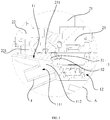
Fig. 1 is a front elevational view of an indoor unit according to an embodiment of the present disclosure, in which a chassis is mounted with a washing module; -
FIG. 2 is a cross sectional view along S-S line as shown inFIG. 1 ; -
FIG. 3 is an enlarged view of portion A as shown inFIG. 2 . -
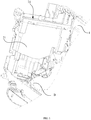
FIG. 4 is a structure diagram of the chassis and the washing module inFIG. 1 , shown from a first view; -
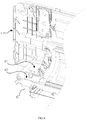
FIG. 5 is a structure diagram of the chassis and the washing module inFIG. 1 , shown from a second view; -
FIG. 6 is an enlarged diagram of portion B as shown inFIG. 5 . -
FIG. 7 is a structure diagram of the washing module as shown inFIG. 5 . -
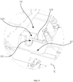
FIG. 7 is a structure diagram of a part of the chassis as shown inFIG. 1 . -
FIG. 9 is an enlarged diagram of portion C as shown inFIG. 8 . - The implementation, functional features and advantages of the present disclosure will be further described with reference to the accompanying drawings.
- As following, the technical solution in the embodiments of the present disclosure will be described clearly and completely with reference to the drawings in the embodiment of the present disclosure. Obviously, the described embodiment is only a part of the embodiment of the present disclosure, not all of the embodiments. Based on the embodiments in the present disclosure, all other embodiments perceived by those ordinary skills in the art without creative effort should be fallen within the protection scope of the present disclosure.
- It should be noted that if directional indications (such as up, down, left, right, front, back, etc.) are involved in the embodiments of the present disclosure, the directional indications are only used to explain the relative positional relationship and movement between the components in a certain posture (as shown in the drawings), and if the specific posture changes, the directional indications will change accordingly.
- In addition, if there are descriptions of "first" and "second" in the embodiments of this disclosure, the descriptions of "first" and "second" are used for descriptive purposes only and cannot be understood as indicating or implying their relative importance or implicitly indicating the number of indicated technical features. Thus, features defining "first" and "second" may explicitly or implicitly include at least one such feature. In addition, the technical solutions between the various embodiments may be combined with each other, but must be based on what one of ordinary skill in the art can achieve. When the combination of technical solutions is contradictory or impossible to achieve, it should be considered that the combination of such technical solutions does not exist and is not within the protection scope required by the present disclosure.
- The present disclosure provides an indoor unit of an air conditioner.
- Please referring to
FIGS. 2 ,6 and9 , in one embodiment of the present disclosure, the indoor unit includes achassis 1, a washing module 2, and awater retaining structure 3. Thechassis 1 includes acondensate area 11 and aneffluent area 12 adjacent to thecondensate area 12 and positioned above thecondensate area 12. A portion of a bottom of theeffluent area 11 adjacent to thecondensate area 12 defines awater outlet hole 111. The washing module 2 is mounted on thechassis 1 and has awater box 21, adischarge pipe 22 communicated with thewater box 21, and awater pump 23 arranged at a lower end of thewater pump 23. Thewater pump 23 is extended into thecondensate area 12 and is configured to pump condensate water into thewater box 21. Thedischarge pipe 22 is extended into theeffluent area 11. The effluent in thewater box 21 can be guided into theeffluent area 12, then drained out through thewater outlet hole 111. Thewater retaining structure 3 is arranged between thecondensate area 12 and theeffluent area 11. - It needs to be noted that, in the embodiment, the indoor unit of the air conditioner is referred to as a fresh air type indoor unit of a wall-mounted air conditioner. Of course, the technical solution of the present disclosure can also be applied to other types of indoor units which are provided with the filter screen. The indoor unit of the present disclosure not only includes some common main components, such as housing, heat exchanger (not shown) received in the housing, wind turbine (not shown), and filter screen (not shown), but also includes fresh air device (not shown). In one embodiment, the fresh air device is usually located in one end of the housing, and an air inlet cavity is defined in the fresh air device and communicated to the outdoor environment by a fresh air inlet pipe. The filter screen is set in a grille assembly (not shown) at the top of the housing and is connected to the washing module 2. The grille assembly includes a first grille and a second grille that are partially overlapped with and detachably connected to the first grille. A first cavity is defined between the first grille and the second grille, and a second cavity is defined between the second grille and an inlet air barrier.
- Here, the washing module 2 normally includes a rotating shaft (not shown), a brush component (not shown), and drive device (not shown). The drive device is configured to drive related parts to rotate to enable the soft filter screen to wrap around on the rotating shaft, and the brush component adjacent to the filter screen can contact with filter screen wrapped around on the rotating shaft and clean the filter screen. Meanwhile, the filter screen is rotated with the rotating shaft, one end of the filter screen is entered into the second cavity, and gradually expanded and received in the second chamber along the direction away from the rotating shaft. Of course, when the rotating shaft is rotated in the opposite direction, the filter screen can be gradually wrapped around on the rotating shaft from the second chamber, then can be gradually expanded in the first chamber to complete the cleaning of the filter screen again. These cleaning processes are automatically completed under the control of air conditioner, which avoids dismounting and cleaning the filter screen manually, so the cleaning process of the filter screen is very convenient. In addition, as shown in
FIG. 4 andFIG. 5 , the washing module 2 also includes awater tank 24 at the upper end ofwater box 21, and the brush component is at least partially located inwater tank 24. When the washing module 2 works, thewater pump 23 at the lower end of thewater box 21 pumps the condensate water in thecondensate area 12 to thewater box 21, for filling thewater tank 24 with clean condensate water. The hairs of the brush of the brush component is contacted with filter screen, for cleaning the filter screen from top to bottom, then the dirtied hairs can be cleaned inwater tank 24. Then the effluent can be guided to theeffluent area 11 through thedischarge pipe 22 below theeffluent area 11, and discharged out through theoutlet pipe 4 communicated with theeffluent area 11. However, in common washing module 2, thecondensate area 12 containing the condensate water is also communicated with theoutlet pipe 4, and thecondensate area 12 is normally arranged near to theeffluent area 11, the effluent from theeffluent area 11 is prone to flow into thecondensate area 12, resulting in a contamination of condensed water, and further reducing the clean effect of the filter screen. - In the embodiment, the
water retaining structure 3 is arranged between thecondensate area 12 and theeffluent area 11; one end of thewater retaining structure 3 is connected to the washing module 2, and the other end of thewater retaining structure 3 is in front of thewater outlet hole 111 to shield a part of thewater outlet hole 111. When the washing module 2 works, the effluent in theeffluent area 11 which is above thecondensate area 12 is blocked by thewater retaining structure 3, and guided to thewater outlet hole 111. As such effluent would not flow into thecondensate area 12 which is below theeffluent area 11, thereby effectively preventing the effluent from polluting the clean condensate water in thecondensate area 12, further improving the cleaning effect of filter screen. Therefore, it is conducive to reducing health problems associated with the use of air conditioner. - Referring to
FIGS. 3 and9 , in the embodiment, the bottom of theeffluent area 11 is inclined downwards to thecondensate area 12. Of course, in another embodiments, the bottom of theeffluent area 11 is not configured to incline. While, in the embodiment, the inclined bottom of theeffluent area 11 is beneficial to drain the effluent in thedischarge pipe 22 out, so the effluent is not prone to accumulate ineffluent area 11. Therefore, it is beneficial to improve the cleanliness of air conditioner. - Specifically, in the embodiment, the bottom of the
effluent area 11 defines an avoidinggroove 112, a side of the avoidinggroove 112 facing thecondensate area 12 defines a notch communicated with thecondensate area 12, a side wall of the avoidinggroove 112 opposite to thecondensate area 12 defines awater outlet hole 111 communicated with theoutlet pipe 4 of the indoor unit. As such, the arrangement of the avoidinggroove 112 can give an enough space for conveniently arranging thewater retaining structure 3 and preventing sewage from blockingwater outlet hole 111 at a certain degree. Here, as shown inFIGS. 2 to 4 , theoutlet pipe 4 is normally inclined backwards and downwards, for discharging the effluent and the overflowed condensate water rapidly. Meanwhile, the setting of the avoidinggroove 112 can allow enough space, thus facilitating the setting of thewater retaining structure 3, but also has a certain degree to prevent sewage in the pollution blockingdrainage hole 111 function. In addition, in one embodiment, as shown inFIGS. 3 ,5 and6 , the retainingstructure 3 is extended into the avoidinggroove 112, the upper end of thewater retaining structure 3 is connected to the wash module 2, the lower end of the water-blockingstructure 3 is located in front of thewater outlet hole 111 to partially obscure thewater outlet hole 111, and the lower edge of thewater retaining structure 3 is positioned lower than a portion of the bottom of theeffluent area 11 extended downwards to thewater retaining structure 3 and contacted with thewater retaining structure 3, for further blocking the effluent from flowing downwards. - Referring to
FIGS. 3 and7 , in the embodiment, thewater pump 23 includes a protrudingedge 231 protruded outwards from an upper edge of thewater pump 23 and detachably connected to the lower end of thewater box 21. Specifically, the protrudingedge 231 is detachably connected with thewater box 21 through a screw, etc., and thewater box 21 can be taken out easily for subsequent repair and replacement. Thewater retaining structure 3 includes awater baffle 31 extended downwards from the protrudingedge 231, and asupport board 32 extended upwards from a lower edge of thewater baffle 31 and connected to the protrudingedge 231. Referring toFIG. 3 , the cross section of thewater retaining structure 3 is a downward triangle. In addition, thewater retaining structure 3 specifically includes thewater baffle 31 and thesupport board 32, thewater baffle 31 from the protrudingedge 231 extended downward formation, thesupport board 32 from the lower edge of thewater baffle 31 extended forward to the connection with the connectingconvex edge 231 connection, that is, as shown inFigure 3 , thewater retaining structure 3 is cross-sectional for the downward triangular setting. However, this design is not limited to this, in other embodiments, the water-blockingstructure 3 can also only bewater baffle 31, but in this embodiment, thesupport board 32 can play a supporting role on thewater baffle 31, so that the overall strength of thewater retaining structure 3 enhanced,water baffle 31 is not easy to affect the water blocking effect due to bending or folding. However, the design of thewater retaining structure 3 is not limited. In another embodiments, thewater retaining structure 3 can only include awater baffle 31. In the embodiment, thesupport board 32 is configured to support thewater baffle 31 for improving the entail strength of thewater retaining structure 3. As such, thewater baffle 31 is not prone to bend or break for maintaining a good water retaining effect. - Please referring to
FIGS. 3 and7 , in the embodiment, thewater retaining structure 3 is integrally arranged with thewater pump 23. So that, thewater retaining structure 3 and the housing of thewater pump 23 can be manufactured together through the injection process. In this case, the connecting strength between thewater retaining structure 3 and thewater pump 23 is further enhanced. Of course, in other embodiments, thewater retaining structure 3 and thewater pump 23 are individual members, and thewater retaining structure 3 is detachably connected to thewater pump 23. - Referring to
FIGS. 6 and8-9 , in the embodiment, awater retaining flange 113 is protruded forwards and upwards from a lower edge of theeffluent area 11. Understandably, theeffluent area 11 is positioned above thecondensate area 12, so thewater retaining flange 113 can effectively prevent effluent from entering thecondensate area 12. And thewater retaining flange 113 is cooperated with thewater retaining structure 3 to guide the effluent in theeffluent area 11 to flow into the avoidinggroove 112, then the effluent would flow into thedischarge pipe 4 through thewater outlet hole 111. In one embodiment, thewater retaining flange 113 is abutted against thewater retaining structure 3, so that there is no gap where thewater retaining flange 113 and thewater retaining structure 3 come into contact, thus further preventing effluent from entering thecondensate area 12. In addition, in one embodiment, the avoidinggroove 112 and thewater outlet hole 111 are both defined in a side of theeffluent area 11 away from the heat exchanger of the indoor unit, for avoid the splashing effluent from damaging the heat exchanger and other components as much as possible. - In addition, referring to
FIGS. 3 and7 , in the embodiment, thedischarge pipe 22 includes adischarge end 221 facing theeffluent area 11. Thedischarge end 221 is gradually expanded in a downward direction for discharging the effluent carrying dusts smoothly. A lower end surface of thedischarge end 221 is inclined downwards to thecondensate area 12, and a gap is defined between the lower end surface of thedischarge end 221 and the bottom of theeffluent area 11. In one embodiment, an inclination angle of the lower end surface of thedischarge end 221 is consistent with that of the bottom of theeffluent area 11, for preventing the effluent, discharged from an opening of the dischargingend 221, from being splashed. As such the effluent could not splash into thecondensate area 12. - The present disclosure also provides an air conditioner which includes an indoor unit. The specific structure of the indoor unit can be referred to the above embodiments. Since the air conditioner takes all the technical solutions of the aforementioned embodiments, it has at least all the beneficial effects brought by the technical solutions of these embodiments, which will thus not be described in detail herein.
- The above description refers to only optional embodiments of the present disclosure, and thus does not limit the scope of the present disclosure, and any transformation of equivlent structure made under the inventive concept of the present disclosure by using the contents of this specification and attached drawings, or direct/indirect application in other relevant technical fields, shall be included in the scope of the present disclosure.
Claims (20)
- An indoor unit of an air conditioner, comprising:a chassis comprising:a condensate area; andan effluent area adjacent to the condensate area and positioned above the condensate area, wherein a portion of a bottom of the effluent area adjacent to the condensate area defines a water outlet hole;a washing module mounted on the chassis and comprising a discharge pipe extending into the effluent area; anda water retaining structure arranged between the condensate area and the effluent area.
- The indoor unit according to claim 1,
wherein the bottom of the effluent area is inclined downwards to the condensate area. - The indoor unit according to claim 1, further comprising:an outlet pipe communicated with the water outlet hole,wherein the bottom of the effluent area defines an avoiding groove, a side of the avoiding groove facing the condensate area defines a notch communicated with the condensate area, and a side of the avoiding groove opposite to the condensate area defines the water outlet hole, andwherein the water retaining structure is extended into the avoiding groove, wherein a top end of the water retaining structure is connected to the washing module; and a lower end of the water retaining structure is in front of the water outlet hole and configured to shield a part of the water outlet hole.
- The indoor unit according to claim 1,
wherein a lower edge of the water retaining structure is positioned lower than a portion of the bottom of the effluent area extended downwards to the water retaining structure and contacted with the water retaining structure. - The indoor unit according to claim 2,
wherein the washing module further comprises:a water box; anda water pump mounted to a lower end of the water box and comprising:
a protruding edge protruded outwards from an upper edge of the water pump and detachably connected to the lower end of the water box, wherein the water retaining structure is arranged on the protruding edge. - The indoor unit according to claim 5,
wherein the water retaining structure comprises:a water baffle extended downwards from the protruding edge; anda support board extended forwards and upwards from a lower edge of the water baffle and connected to the protruding edge. - The indoor unit according to claim 5, wherein the water retaining structure is integrally arranged with the water pump.
- The indoor unit according to claim 2, wherein further comprising:
a water retaining flange protruded forwards and upwards from a lower edge of the effluent area. - The indoor unit according to claim 1, wherein the water retaining flange is abutted against the water retaining structure.
- The indoor unit according to claim 1,
wherein the discharge pipe comprises:
a discharge end facing the effluent area, with an opening of the discharge end flared downwards. - The indoor unit according to claim 10,
wherein a lower end surface of the discharge end is inclined downwards and towards the condensate area, and
wherein a gap is defined between the lower end surface of the discharge end and the bottom of the effluent area. - The indoor unit according to claim 11,
wherein an inclination angle of the lower end surface of the discharge end is consistent with an inclination angle of the bottom of the effluent area. - An air conditioner comprising:
an indoor unit comprising:a chassis comprising:a condensate area; andan effluent area adjacent to the condensate area and positioned above the condensate area, wherein a portion of a bottom of the effluent area adjacent to the condensate area defines a water outlet hole;a washing module mounted on the chassis and comprising a discharge pipe extending into the effluent area; anda water retaining structure arranged between the condensate area and the effluent area. - The air conditioner according to claim 13,
wherein the bottom of the effluent area is inclined downwards to the condensate area. - The air conditioner according to claim 13, wherein further comprising:an outlet pipe,wherein the bottom of the effluent area defines an avoiding groove, a side of the avoiding groove facing the condensate area defines a notch communicated with the condensate area, and a side of the avoiding groove opposite to the condensate area defines the water outlet hole, andwherein the water retaining structure is extended into the avoiding groove, wherein a top end of the water retaining structure is connected to the washing module; and a lower end of the water retaining structure is in front of the water outlet hole and configured to shield a part of the water outlet hole.
- The air conditioner according to claim 13,
wherein a lower edge of the water retaining structure is positioned lower than a portion of the bottom of the effluent area extended downwards to the water retaining structure and contacted with the water retaining structure. - The air conditioner according to claim 14, wherein
wherein the washing module further comprises:a water box; anda water pump mounted to a lower end of the water box and comprising:
a protruding edge protruded outwards from an upper edge of the water pump and detachably connected to the lower end of the water box, wherein the water retaining structure is arranged on the protruding edge. - The air conditioner according to claim 17, wherein
wherein the water retaining structure comprises:a water baffle extended downwards from the protruding edge; anda support board extended forwards and upwards from a lower edge of the water baffle and connected to the protruding edge. - The air conditioner according to claim 14, wherein the water retaining structure is integrally arranged with the water pump.
- The air conditioner according to claim 14, further comprising:
a water retaining flange protruded forwards and upwards from a lower edge of the effluent area, and abutted against the water retaining structure.
Applications Claiming Priority (3)
| Application Number | Priority Date | Filing Date | Title |
|---|---|---|---|
| CN201910158195.5A CN110017534B (en) | 2019-03-03 | 2019-03-03 | Air conditioner indoor unit and air conditioner |
| CN201920268071.8U CN209672460U (en) | 2019-03-03 | 2019-03-03 | Air conditioner indoor unit and air conditioner |
| PCT/CN2019/112442 WO2020177331A1 (en) | 2019-03-03 | 2019-10-22 | Air conditioner indoor unit and air conditioner |
Publications (3)
| Publication Number | Publication Date |
|---|---|
| EP3734169A1 true EP3734169A1 (en) | 2020-11-04 |
| EP3734169A4 EP3734169A4 (en) | 2020-11-04 |
| EP3734169B1 EP3734169B1 (en) | 2023-04-26 |
Family
ID=70049810
Family Applications (1)
| Application Number | Title | Priority Date | Filing Date |
|---|---|---|---|
| EP19798159.0A Active EP3734169B1 (en) | 2019-03-03 | 2019-10-22 | Air conditioner indoor unit and air conditioner |
Country Status (4)
| Country | Link |
|---|---|
| US (1) | US12181176B2 (en) |
| EP (1) | EP3734169B1 (en) |
| JP (1) | JP6903166B1 (en) |
| WO (1) | WO2020177331A1 (en) |
Cited By (1)
| Publication number | Priority date | Publication date | Assignee | Title |
|---|---|---|---|---|
| CN115111769A (en) * | 2022-07-18 | 2022-09-27 | 珠海格力节能环保制冷技术研究中心有限公司 | Supporting structure and air conditioner with same |
Family Cites Families (20)
| Publication number | Priority date | Publication date | Assignee | Title |
|---|---|---|---|---|
| JP2003021495A (en) * | 2001-07-05 | 2003-01-24 | Daikin Ind Ltd | Air conditioner |
| JP2005036996A (en) * | 2003-07-16 | 2005-02-10 | Sharp Corp | Air conditioner and hose shape correction tool |
| EP2064495A4 (en) * | 2006-09-20 | 2010-08-04 | Lg Electronics Inc | AIR CONDITIONER |
| ES2639179T3 (en) * | 2007-09-04 | 2017-10-25 | Lg Electronics Inc. | Dehumidifying device for dryer |
| KR101573215B1 (en) * | 2008-12-23 | 2015-12-01 | 삼성전자 주식회사 | Cleaning device of an air conditioner and control method thereof |
| KR101649974B1 (en) | 2009-05-06 | 2016-08-23 | 삼성전자 주식회사 | Condensed water storage tank apparatus for auto cleaning device and air conditioner having the same |
| JP2012163297A (en) * | 2011-02-09 | 2012-08-30 | Syscom Kankyo Technology:Kk | Built-in type cleaning device of air conditioner |
| US10443888B2 (en) * | 2015-03-06 | 2019-10-15 | Mitsubishi Electric Corporation | Air conditioner |
| JP6603125B2 (en) * | 2015-12-25 | 2019-11-06 | シャープ株式会社 | Air conditioner |
| CN106642328A (en) * | 2016-11-30 | 2017-05-10 | 广东美的制冷设备有限公司 | Air conditioner |
| CN106767124B (en) | 2016-11-30 | 2019-04-02 | 美的集团武汉制冷设备有限公司 | Air conditioner evaporator water washing control method, device and air conditioner |
| CN106767125B (en) * | 2016-11-30 | 2019-04-19 | 美的集团武汉制冷设备有限公司 | Air conditioner evaporator water washing control method, device and air conditioner |
| CN106765924B (en) | 2016-12-09 | 2019-10-25 | 美的集团武汉制冷设备有限公司 | Air conditioner and cleaning control method thereof |
| CN107435997B (en) * | 2017-07-21 | 2020-08-25 | 广东美的制冷设备有限公司 | Air conditioner indoor unit and air conditioner with same |
| CN108895573A (en) * | 2018-05-31 | 2018-11-27 | 海信(山东)空调有限公司 | The cleaning device and air-cooled ducted air conditioner of air-cooled ducted air conditioner filter screen |
| CN108731204B (en) | 2018-06-08 | 2021-02-09 | 广东美的制冷设备有限公司 | Purification control method of air conditioner, air conditioner and readable storage medium |
| CN208566876U (en) * | 2018-06-08 | 2019-03-01 | 广东美的制冷设备有限公司 | Air conditioner indoor unit and air conditioner |
| KR20180098480A (en) * | 2018-08-15 | 2018-09-04 | 김형순 | A air conditioner indoor unit |
| CN209672460U (en) | 2019-03-03 | 2019-11-22 | 广东美的制冷设备有限公司 | Air conditioner indoor unit and air conditioner |
| CN110017534B (en) * | 2019-03-03 | 2024-04-26 | 广东美的制冷设备有限公司 | Air conditioner indoor unit and air conditioner |
-
2019
- 2019-10-22 JP JP2019563831A patent/JP6903166B1/en active Active
- 2019-10-22 EP EP19798159.0A patent/EP3734169B1/en active Active
- 2019-10-22 WO PCT/CN2019/112442 patent/WO2020177331A1/en not_active Ceased
-
2021
- 2021-08-24 US US17/409,898 patent/US12181176B2/en active Active
Cited By (1)
| Publication number | Priority date | Publication date | Assignee | Title |
|---|---|---|---|---|
| CN115111769A (en) * | 2022-07-18 | 2022-09-27 | 珠海格力节能环保制冷技术研究中心有限公司 | Supporting structure and air conditioner with same |
Also Published As
| Publication number | Publication date |
|---|---|
| JP2021517628A (en) | 2021-07-26 |
| US12181176B2 (en) | 2024-12-31 |
| WO2020177331A1 (en) | 2020-09-10 |
| EP3734169B1 (en) | 2023-04-26 |
| US20210404701A1 (en) | 2021-12-30 |
| EP3734169A4 (en) | 2020-11-04 |
| JP6903166B1 (en) | 2021-07-14 |
Similar Documents
| Publication | Publication Date | Title |
|---|---|---|
| CN208059117U (en) | Ceiling machine | |
| WO2019206244A1 (en) | Portable air conditioner | |
| US12181176B2 (en) | Indoor unit of air conditioner, and air conditioner | |
| CN115446004B (en) | Air conditioning cleaning structure and cleaning method | |
| CN108674131A (en) | New energy automobile air conditioner heat abstractor | |
| CN209672460U (en) | Air conditioner indoor unit and air conditioner | |
| CN108534238A (en) | Air conditioner indoor unit and air conditioner | |
| CN222047916U (en) | Indoor unit and HVAC equipment | |
| CN110017534B (en) | Air conditioner indoor unit and air conditioner | |
| CN106016678A (en) | Frame assembly and wall mounting type air conditioner indoor unit | |
| CN220229323U (en) | Air outlet structure of integrated kitchen and integrated kitchen | |
| CN110820254B (en) | A wall-mounted washing machine | |
| CN214250012U (en) | Washing air device | |
| CN205878354U (en) | Wall -mounted air conditioner indoor unit and air conditioner | |
| CN106051923B (en) | Wall-mounted air conditioner indoor unit and air conditioner | |
| CN213713251U (en) | Air conditioner indoor unit and air conditioner | |
| CN206626688U (en) | Indoor apparatus of air conditioner | |
| CN103939990A (en) | Indoor unit of air conditioner | |
| CN113124500B (en) | Window Air Conditioner | |
| CN223047299U (en) | Slow flow defoaming structure and PCB cleaning device | |
| CN210601927U (en) | Air conditioner indoor unit and air conditioner | |
| CN205878545U (en) | Framework subassembly and wall -mounted air conditioner indoor unit | |
| CN218820943U (en) | Special water collector of integral type air conditioner | |
| CN220169516U (en) | Bellows structure for integrated kitchen | |
| CN107355864B (en) | Air treatment module and air conditioner |
Legal Events
| Date | Code | Title | Description |
|---|---|---|---|
| STAA | Information on the status of an ep patent application or granted ep patent |
Free format text: STATUS: UNKNOWN |
|
| STAA | Information on the status of an ep patent application or granted ep patent |
Free format text: STATUS: THE INTERNATIONAL PUBLICATION HAS BEEN MADE |
|
| PUAI | Public reference made under article 153(3) epc to a published international application that has entered the european phase |
Free format text: ORIGINAL CODE: 0009012 |
|
| STAA | Information on the status of an ep patent application or granted ep patent |
Free format text: STATUS: REQUEST FOR EXAMINATION WAS MADE |
|
| 17P | Request for examination filed |
Effective date: 20191114 |
|
| A4 | Supplementary search report drawn up and despatched |
Effective date: 20200908 |
|
| AK | Designated contracting states |
Kind code of ref document: A1 Designated state(s): AL AT BE BG CH CY CZ DE DK EE ES FI FR GB GR HR HU IE IS IT LI LT LU LV MC MK MT NL NO PL PT RO RS SE SI SK SM TR |
|
| AX | Request for extension of the european patent |
Extension state: BA ME |
|
| RAP3 | Party data changed (applicant data changed or rights of an application transferred) |
Owner name: MIDEA GROUP CO., LTD. Owner name: GD MIDEA AIR-CONDITIONING EQUIPMENT CO., LTD. |
|
| DAV | Request for validation of the european patent (deleted) | ||
| DAX | Request for extension of the european patent (deleted) | ||
| GRAP | Despatch of communication of intention to grant a patent |
Free format text: ORIGINAL CODE: EPIDOSNIGR1 |
|
| STAA | Information on the status of an ep patent application or granted ep patent |
Free format text: STATUS: GRANT OF PATENT IS INTENDED |
|
| INTG | Intention to grant announced |
Effective date: 20230209 |
|
| GRAS | Grant fee paid |
Free format text: ORIGINAL CODE: EPIDOSNIGR3 |
|
| GRAA | (expected) grant |
Free format text: ORIGINAL CODE: 0009210 |
|
| STAA | Information on the status of an ep patent application or granted ep patent |
Free format text: STATUS: THE PATENT HAS BEEN GRANTED |
|
| AK | Designated contracting states |
Kind code of ref document: B1 Designated state(s): AL AT BE BG CH CY CZ DE DK EE ES FI FR GB GR HR HU IE IS IT LI LT LU LV MC MK MT NL NO PL PT RO RS SE SI SK SM TR |
|
| REG | Reference to a national code |
Ref country code: GB Ref legal event code: FG4D |
|
| REG | Reference to a national code |
Ref country code: CH Ref legal event code: EP |
|
| REG | Reference to a national code |
Ref country code: DE Ref legal event code: R096 Ref document number: 602019028116 Country of ref document: DE |
|
| REG | Reference to a national code |
Ref country code: AT Ref legal event code: REF Ref document number: 1563081 Country of ref document: AT Kind code of ref document: T Effective date: 20230515 |
|
| REG | Reference to a national code |
Ref country code: IE Ref legal event code: FG4D |
|
| REG | Reference to a national code |
Ref country code: LT Ref legal event code: MG9D |
|
| REG | Reference to a national code |
Ref country code: NL Ref legal event code: MP Effective date: 20230426 |
|
| REG | Reference to a national code |
Ref country code: AT Ref legal event code: MK05 Ref document number: 1563081 Country of ref document: AT Kind code of ref document: T Effective date: 20230426 |
|
| PG25 | Lapsed in a contracting state [announced via postgrant information from national office to epo] |
Ref country code: NL Free format text: LAPSE BECAUSE OF FAILURE TO SUBMIT A TRANSLATION OF THE DESCRIPTION OR TO PAY THE FEE WITHIN THE PRESCRIBED TIME-LIMIT Effective date: 20230426 |
|
| PG25 | Lapsed in a contracting state [announced via postgrant information from national office to epo] |
Ref country code: SE Free format text: LAPSE BECAUSE OF FAILURE TO SUBMIT A TRANSLATION OF THE DESCRIPTION OR TO PAY THE FEE WITHIN THE PRESCRIBED TIME-LIMIT Effective date: 20230426 Ref country code: PT Free format text: LAPSE BECAUSE OF FAILURE TO SUBMIT A TRANSLATION OF THE DESCRIPTION OR TO PAY THE FEE WITHIN THE PRESCRIBED TIME-LIMIT Effective date: 20230828 Ref country code: NO Free format text: LAPSE BECAUSE OF FAILURE TO SUBMIT A TRANSLATION OF THE DESCRIPTION OR TO PAY THE FEE WITHIN THE PRESCRIBED TIME-LIMIT Effective date: 20230726 Ref country code: ES Free format text: LAPSE BECAUSE OF FAILURE TO SUBMIT A TRANSLATION OF THE DESCRIPTION OR TO PAY THE FEE WITHIN THE PRESCRIBED TIME-LIMIT Effective date: 20230426 Ref country code: AT Free format text: LAPSE BECAUSE OF FAILURE TO SUBMIT A TRANSLATION OF THE DESCRIPTION OR TO PAY THE FEE WITHIN THE PRESCRIBED TIME-LIMIT Effective date: 20230426 |
|
| PG25 | Lapsed in a contracting state [announced via postgrant information from national office to epo] |
Ref country code: RS Free format text: LAPSE BECAUSE OF FAILURE TO SUBMIT A TRANSLATION OF THE DESCRIPTION OR TO PAY THE FEE WITHIN THE PRESCRIBED TIME-LIMIT Effective date: 20230426 Ref country code: PL Free format text: LAPSE BECAUSE OF FAILURE TO SUBMIT A TRANSLATION OF THE DESCRIPTION OR TO PAY THE FEE WITHIN THE PRESCRIBED TIME-LIMIT Effective date: 20230426 Ref country code: LV Free format text: LAPSE BECAUSE OF FAILURE TO SUBMIT A TRANSLATION OF THE DESCRIPTION OR TO PAY THE FEE WITHIN THE PRESCRIBED TIME-LIMIT Effective date: 20230426 Ref country code: LT Free format text: LAPSE BECAUSE OF FAILURE TO SUBMIT A TRANSLATION OF THE DESCRIPTION OR TO PAY THE FEE WITHIN THE PRESCRIBED TIME-LIMIT Effective date: 20230426 Ref country code: IS Free format text: LAPSE BECAUSE OF FAILURE TO SUBMIT A TRANSLATION OF THE DESCRIPTION OR TO PAY THE FEE WITHIN THE PRESCRIBED TIME-LIMIT Effective date: 20230826 Ref country code: HR Free format text: LAPSE BECAUSE OF FAILURE TO SUBMIT A TRANSLATION OF THE DESCRIPTION OR TO PAY THE FEE WITHIN THE PRESCRIBED TIME-LIMIT Effective date: 20230426 Ref country code: GR Free format text: LAPSE BECAUSE OF FAILURE TO SUBMIT A TRANSLATION OF THE DESCRIPTION OR TO PAY THE FEE WITHIN THE PRESCRIBED TIME-LIMIT Effective date: 20230727 |
|
| PG25 | Lapsed in a contracting state [announced via postgrant information from national office to epo] |
Ref country code: FI Free format text: LAPSE BECAUSE OF FAILURE TO SUBMIT A TRANSLATION OF THE DESCRIPTION OR TO PAY THE FEE WITHIN THE PRESCRIBED TIME-LIMIT Effective date: 20230426 |
|
| PG25 | Lapsed in a contracting state [announced via postgrant information from national office to epo] |
Ref country code: SK Free format text: LAPSE BECAUSE OF FAILURE TO SUBMIT A TRANSLATION OF THE DESCRIPTION OR TO PAY THE FEE WITHIN THE PRESCRIBED TIME-LIMIT Effective date: 20230426 |
|
| REG | Reference to a national code |
Ref country code: DE Ref legal event code: R097 Ref document number: 602019028116 Country of ref document: DE |
|
| PG25 | Lapsed in a contracting state [announced via postgrant information from national office to epo] |
Ref country code: SM Free format text: LAPSE BECAUSE OF FAILURE TO SUBMIT A TRANSLATION OF THE DESCRIPTION OR TO PAY THE FEE WITHIN THE PRESCRIBED TIME-LIMIT Effective date: 20230426 Ref country code: SK Free format text: LAPSE BECAUSE OF FAILURE TO SUBMIT A TRANSLATION OF THE DESCRIPTION OR TO PAY THE FEE WITHIN THE PRESCRIBED TIME-LIMIT Effective date: 20230426 Ref country code: RO Free format text: LAPSE BECAUSE OF FAILURE TO SUBMIT A TRANSLATION OF THE DESCRIPTION OR TO PAY THE FEE WITHIN THE PRESCRIBED TIME-LIMIT Effective date: 20230426 Ref country code: EE Free format text: LAPSE BECAUSE OF FAILURE TO SUBMIT A TRANSLATION OF THE DESCRIPTION OR TO PAY THE FEE WITHIN THE PRESCRIBED TIME-LIMIT Effective date: 20230426 Ref country code: DK Free format text: LAPSE BECAUSE OF FAILURE TO SUBMIT A TRANSLATION OF THE DESCRIPTION OR TO PAY THE FEE WITHIN THE PRESCRIBED TIME-LIMIT Effective date: 20230426 Ref country code: CZ Free format text: LAPSE BECAUSE OF FAILURE TO SUBMIT A TRANSLATION OF THE DESCRIPTION OR TO PAY THE FEE WITHIN THE PRESCRIBED TIME-LIMIT Effective date: 20230426 |
|
| PLBE | No opposition filed within time limit |
Free format text: ORIGINAL CODE: 0009261 |
|
| STAA | Information on the status of an ep patent application or granted ep patent |
Free format text: STATUS: NO OPPOSITION FILED WITHIN TIME LIMIT |
|
| 26N | No opposition filed |
Effective date: 20240129 |
|
| PG25 | Lapsed in a contracting state [announced via postgrant information from national office to epo] |
Ref country code: SI Free format text: LAPSE BECAUSE OF FAILURE TO SUBMIT A TRANSLATION OF THE DESCRIPTION OR TO PAY THE FEE WITHIN THE PRESCRIBED TIME-LIMIT Effective date: 20230426 |
|
| PG25 | Lapsed in a contracting state [announced via postgrant information from national office to epo] |
Ref country code: SI Free format text: LAPSE BECAUSE OF FAILURE TO SUBMIT A TRANSLATION OF THE DESCRIPTION OR TO PAY THE FEE WITHIN THE PRESCRIBED TIME-LIMIT Effective date: 20230426 Ref country code: IT Free format text: LAPSE BECAUSE OF FAILURE TO SUBMIT A TRANSLATION OF THE DESCRIPTION OR TO PAY THE FEE WITHIN THE PRESCRIBED TIME-LIMIT Effective date: 20230426 Ref country code: MC Free format text: LAPSE BECAUSE OF FAILURE TO SUBMIT A TRANSLATION OF THE DESCRIPTION OR TO PAY THE FEE WITHIN THE PRESCRIBED TIME-LIMIT Effective date: 20230426 |
|
| REG | Reference to a national code |
Ref country code: CH Ref legal event code: PL |
|
| REG | Reference to a national code |
Ref country code: BE Ref legal event code: MM Effective date: 20231031 |
|
| PG25 | Lapsed in a contracting state [announced via postgrant information from national office to epo] |
Ref country code: LU Free format text: LAPSE BECAUSE OF NON-PAYMENT OF DUE FEES Effective date: 20231022 |
|
| GBPC | Gb: european patent ceased through non-payment of renewal fee |
Effective date: 20231022 |
|
| PG25 | Lapsed in a contracting state [announced via postgrant information from national office to epo] |
Ref country code: LU Free format text: LAPSE BECAUSE OF NON-PAYMENT OF DUE FEES Effective date: 20231022 |
|
| PG25 | Lapsed in a contracting state [announced via postgrant information from national office to epo] |
Ref country code: GB Free format text: LAPSE BECAUSE OF NON-PAYMENT OF DUE FEES Effective date: 20231022 |
|
| PG25 | Lapsed in a contracting state [announced via postgrant information from national office to epo] |
Ref country code: CH Free format text: LAPSE BECAUSE OF NON-PAYMENT OF DUE FEES Effective date: 20231031 |
|
| PG25 | Lapsed in a contracting state [announced via postgrant information from national office to epo] |
Ref country code: GB Free format text: LAPSE BECAUSE OF NON-PAYMENT OF DUE FEES Effective date: 20231022 Ref country code: FR Free format text: LAPSE BECAUSE OF NON-PAYMENT OF DUE FEES Effective date: 20231031 Ref country code: CH Free format text: LAPSE BECAUSE OF NON-PAYMENT OF DUE FEES Effective date: 20231031 |
|
| PG25 | Lapsed in a contracting state [announced via postgrant information from national office to epo] |
Ref country code: BE Free format text: LAPSE BECAUSE OF NON-PAYMENT OF DUE FEES Effective date: 20231031 |
|
| PG25 | Lapsed in a contracting state [announced via postgrant information from national office to epo] |
Ref country code: IE Free format text: LAPSE BECAUSE OF NON-PAYMENT OF DUE FEES Effective date: 20231022 |
|
| PG25 | Lapsed in a contracting state [announced via postgrant information from national office to epo] |
Ref country code: IE Free format text: LAPSE BECAUSE OF NON-PAYMENT OF DUE FEES Effective date: 20231022 |
|
| PG25 | Lapsed in a contracting state [announced via postgrant information from national office to epo] |
Ref country code: BG Free format text: LAPSE BECAUSE OF FAILURE TO SUBMIT A TRANSLATION OF THE DESCRIPTION OR TO PAY THE FEE WITHIN THE PRESCRIBED TIME-LIMIT Effective date: 20230426 |
|
| PG25 | Lapsed in a contracting state [announced via postgrant information from national office to epo] |
Ref country code: BG Free format text: LAPSE BECAUSE OF FAILURE TO SUBMIT A TRANSLATION OF THE DESCRIPTION OR TO PAY THE FEE WITHIN THE PRESCRIBED TIME-LIMIT Effective date: 20230426 |
|
| PGFP | Annual fee paid to national office [announced via postgrant information from national office to epo] |
Ref country code: DE Payment date: 20241022 Year of fee payment: 6 |
|
| PG25 | Lapsed in a contracting state [announced via postgrant information from national office to epo] |
Ref country code: CY Free format text: LAPSE BECAUSE OF FAILURE TO SUBMIT A TRANSLATION OF THE DESCRIPTION OR TO PAY THE FEE WITHIN THE PRESCRIBED TIME-LIMIT; INVALID AB INITIO Effective date: 20191022 |
|
| PG25 | Lapsed in a contracting state [announced via postgrant information from national office to epo] |
Ref country code: HU Free format text: LAPSE BECAUSE OF FAILURE TO SUBMIT A TRANSLATION OF THE DESCRIPTION OR TO PAY THE FEE WITHIN THE PRESCRIBED TIME-LIMIT; INVALID AB INITIO Effective date: 20191022 |
|
| PG25 | Lapsed in a contracting state [announced via postgrant information from national office to epo] |
Ref country code: TR Free format text: LAPSE BECAUSE OF FAILURE TO SUBMIT A TRANSLATION OF THE DESCRIPTION OR TO PAY THE FEE WITHIN THE PRESCRIBED TIME-LIMIT Effective date: 20230426 |