EP3734130A1 - Sealing gasket and tightening device and assembly comprising such a sealing gasket - Google Patents
Sealing gasket and tightening device and assembly comprising such a sealing gasket Download PDFInfo
- Publication number
- EP3734130A1 EP3734130A1 EP20171694.1A EP20171694A EP3734130A1 EP 3734130 A1 EP3734130 A1 EP 3734130A1 EP 20171694 A EP20171694 A EP 20171694A EP 3734130 A1 EP3734130 A1 EP 3734130A1
- Authority
- EP
- European Patent Office
- Prior art keywords
- seal
- sleeve
- tube
- belt
- collar
- Prior art date
- Legal status (The legal status is an assumption and is not a legal conclusion. Google has not performed a legal analysis and makes no representation as to the accuracy of the status listed.)
- Granted
Links
- 238000007789 sealing Methods 0.000 title claims abstract description 36
- 230000000717 retained effect Effects 0.000 claims abstract description 13
- 125000006850 spacer group Chemical group 0.000 claims description 22
- 239000000463 material Substances 0.000 claims description 13
- 238000000605 extraction Methods 0.000 claims description 11
- 238000006073 displacement reaction Methods 0.000 claims description 6
- 239000010445 mica Substances 0.000 claims description 6
- 229910052618 mica group Inorganic materials 0.000 claims description 6
- 230000037431 insertion Effects 0.000 claims description 3
- 238000003780 insertion Methods 0.000 claims description 3
- 239000002184 metal Substances 0.000 description 6
- 230000000694 effects Effects 0.000 description 4
- 238000004519 manufacturing process Methods 0.000 description 4
- 239000007787 solid Substances 0.000 description 4
- 230000006835 compression Effects 0.000 description 3
- 238000007906 compression Methods 0.000 description 3
- 230000035882 stress Effects 0.000 description 3
- 239000011230 binding agent Substances 0.000 description 2
- 230000007423 decrease Effects 0.000 description 2
- 230000014759 maintenance of location Effects 0.000 description 2
- 238000000926 separation method Methods 0.000 description 2
- 239000010935 stainless steel Substances 0.000 description 2
- 229910001220 stainless steel Inorganic materials 0.000 description 2
- 230000006353 environmental stress Effects 0.000 description 1
Images


Classifications
-
- F—MECHANICAL ENGINEERING; LIGHTING; HEATING; WEAPONS; BLASTING
- F16—ENGINEERING ELEMENTS AND UNITS; GENERAL MEASURES FOR PRODUCING AND MAINTAINING EFFECTIVE FUNCTIONING OF MACHINES OR INSTALLATIONS; THERMAL INSULATION IN GENERAL
- F16L—PIPES; JOINTS OR FITTINGS FOR PIPES; SUPPORTS FOR PIPES, CABLES OR PROTECTIVE TUBING; MEANS FOR THERMAL INSULATION IN GENERAL
- F16L21/00—Joints with sleeve or socket
- F16L21/06—Joints with sleeve or socket with a divided sleeve or ring clamping around the pipe-ends
- F16L21/065—Joints with sleeve or socket with a divided sleeve or ring clamping around the pipe-ends tightened by tangentially-arranged threaded pins
-
- F—MECHANICAL ENGINEERING; LIGHTING; HEATING; WEAPONS; BLASTING
- F16—ENGINEERING ELEMENTS AND UNITS; GENERAL MEASURES FOR PRODUCING AND MAINTAINING EFFECTIVE FUNCTIONING OF MACHINES OR INSTALLATIONS; THERMAL INSULATION IN GENERAL
- F16L—PIPES; JOINTS OR FITTINGS FOR PIPES; SUPPORTS FOR PIPES, CABLES OR PROTECTIVE TUBING; MEANS FOR THERMAL INSULATION IN GENERAL
- F16L23/00—Flanged joints
- F16L23/003—Auxiliary devices
-
- F—MECHANICAL ENGINEERING; LIGHTING; HEATING; WEAPONS; BLASTING
- F16—ENGINEERING ELEMENTS AND UNITS; GENERAL MEASURES FOR PRODUCING AND MAINTAINING EFFECTIVE FUNCTIONING OF MACHINES OR INSTALLATIONS; THERMAL INSULATION IN GENERAL
- F16L—PIPES; JOINTS OR FITTINGS FOR PIPES; SUPPORTS FOR PIPES, CABLES OR PROTECTIVE TUBING; MEANS FOR THERMAL INSULATION IN GENERAL
- F16L21/00—Joints with sleeve or socket
- F16L21/002—Sleeves or nipples for pipes of the same diameter; Reduction pieces
- F16L21/005—Sleeves or nipples for pipes of the same diameter; Reduction pieces made of elastic material, e.g. partly or completely surrounded by clamping devices
-
- F—MECHANICAL ENGINEERING; LIGHTING; HEATING; WEAPONS; BLASTING
- F16—ENGINEERING ELEMENTS AND UNITS; GENERAL MEASURES FOR PRODUCING AND MAINTAINING EFFECTIVE FUNCTIONING OF MACHINES OR INSTALLATIONS; THERMAL INSULATION IN GENERAL
- F16L—PIPES; JOINTS OR FITTINGS FOR PIPES; SUPPORTS FOR PIPES, CABLES OR PROTECTIVE TUBING; MEANS FOR THERMAL INSULATION IN GENERAL
- F16L21/00—Joints with sleeve or socket
- F16L21/02—Joints with sleeve or socket with elastic sealing rings between pipe and sleeve or between pipe and socket, e.g. with rolling or other prefabricated profiled rings
- F16L21/03—Joints with sleeve or socket with elastic sealing rings between pipe and sleeve or between pipe and socket, e.g. with rolling or other prefabricated profiled rings placed in the socket before connection
-
- F—MECHANICAL ENGINEERING; LIGHTING; HEATING; WEAPONS; BLASTING
- F16—ENGINEERING ELEMENTS AND UNITS; GENERAL MEASURES FOR PRODUCING AND MAINTAINING EFFECTIVE FUNCTIONING OF MACHINES OR INSTALLATIONS; THERMAL INSULATION IN GENERAL
- F16L—PIPES; JOINTS OR FITTINGS FOR PIPES; SUPPORTS FOR PIPES, CABLES OR PROTECTIVE TUBING; MEANS FOR THERMAL INSULATION IN GENERAL
- F16L23/00—Flanged joints
- F16L23/04—Flanged joints the flanges being connected by members tensioned in the radial plane
- F16L23/08—Flanged joints the flanges being connected by members tensioned in the radial plane connection by tangentially arranged pin and nut
-
- F—MECHANICAL ENGINEERING; LIGHTING; HEATING; WEAPONS; BLASTING
- F16—ENGINEERING ELEMENTS AND UNITS; GENERAL MEASURES FOR PRODUCING AND MAINTAINING EFFECTIVE FUNCTIONING OF MACHINES OR INSTALLATIONS; THERMAL INSULATION IN GENERAL
- F16L—PIPES; JOINTS OR FITTINGS FOR PIPES; SUPPORTS FOR PIPES, CABLES OR PROTECTIVE TUBING; MEANS FOR THERMAL INSULATION IN GENERAL
- F16L23/00—Flanged joints
- F16L23/16—Flanged joints characterised by the sealing means
- F16L23/18—Flanged joints characterised by the sealing means the sealing means being rings
Definitions
- the present disclosure relates to a seal, as well as to a clamping device and to a clamping assembly comprising such a seal.
- Annular seals are known, produced by a closed ring. To achieve their sealing function, these seals must be compressed and must therefore be formed from materials allowing such compression while having the qualities required to withstand the conditions of the environment in which the seal is placed. tightness, for example in terms of temperature, pressure, or variation of these parameters. In addition, generally, for such closed seals, the difference between the diameter of the seal in the free state and the diameter of the seal in the clamped state, after compression, is generally small. . Thus, these closed type gaskets are not suitable for some applications.
- tightening devices comprising a collar which has a belt capable of being tightened by reducing its diameter and a seal pre-mounted in the collar. More precisely, this system comprises a washer which comprises a closed annular part forming the seal and tabs connecting this seal to the collar. The closed annular seal is initially maintained at a significant distance from the inner periphery of the collar so as to allow engagement of the outer tube between the seal and this inner periphery. Then, the inner tube is itself engaged so as to come into contact with the seal.
- This device is particularly suitable for clamping two tubes fitted together and having flared radially projecting surfaces serving as a support for a clamp which comprises a recess capable of accommodating these flared radially projecting surfaces, the closed annular seal itself having a frustoconical shape adapted to these flared surfaces.
- Open type seals are also known, in particular of the type produced by a strip wound on itself and the ends of which cooperate with one another by a sealing arrangement.
- a seal is for example disclosed by document EP 1 181 477 .
- a seal of this type has the advantage of being easy to manufacture and in particular of making it possible, without very significant change in the manufacturing tool, to manufacture seals of different diameters, since the diameter of the seal sealing depends on the length of the strip in which it is formed.
- a seal of this type can be easily mounted around or inside objects to which it must ensure a sealed connection and can be made of a material which is not necessarily required to deform. notably under radial compression, which makes it possible to choose materials resistant to demanding environmental stresses, for example in terms of temperature, pressure or gradient of these parameters.
- such a seal can be made from a metal of the stainless steel type.
- the opening of the seal that is to say the junction between the ends of the strip in which it is formed, may present a zone of weakness in terms of sealing, despite the fact that the the ends in question cooperate with each other by a sealing arrangement.
- the seal may have a spring effect, i.e. the strip in which it is formed may have a tendency to unroll which, in certain applications, can complicate handling, storage and assembly.
- the disclosure aims to remedy at least substantially the aforementioned drawbacks.
- the disclosure relates to a seal comprising a first and a second coaxial sleeve arranged around each other while being retained with respect to each other, each sleeve being formed by a strip wound on itself, the ends of which are configured to cooperate with each other via a sealing arrangement allowing a reduction in the diameter of the sleeve, the sealing arrangements of the two sleeves being angularly offset.
- each sleeve Due to the angular offset of the sealing arrangements of the two sleeves, the sealing arrangement of each sleeve is "bridged" by the other sleeve.
- the sealing arrangement of each sleeve is radially covered, either on the outside or on the inside, by the strip in which the other sleeve is formed.
- the sleeves are retained with respect to each other, which means that they hold each other. In other words, the presence of each sleeve tends to prevent the other sleeve from tending to unwind or not to retain its desired shape.
- the gasket retains the advantage of open type gaskets in that it is simple to manufacture for different diameters by adjusting the length of the bands in which the two sleeves are formed and in that it performs its sealing function by reducing its diameter bringing the respective ends of the two sleeves closer together.
- the two sleeves are formed from different materials, the strip forming the first sleeve being optionally formed from a mica-based material and the strip forming the second sleeve being optionally metallic.
- the strip forming at least one of the first and second sleeves naturally tends to unwind and is kept rolled up by the other sleeve.
- the sealing arrangement of at least one of the first and second sleeves comprises a male / female engagement conformation.
- At least one of the first and second sleeves has at least one wedging tab, under which one edge of the other sleeve is wedged.
- the present disclosure also relates to a tightening device comprising a collar which has a belt capable of being tightened by reducing its diameter, and a seal according to the present disclosure, in which the seal is disposed inside. of the belt by being retained axially relative to the collar and by being configured to release an annular space allowing the insertion of an annular object between the seal and the belt.
- this clamping device makes it possible to use a seal functioning as an open type seal pre-mounted in a collar.
- the annular space allows the insertion of an annular object such as the end of a tube between the belt and the seal.
- the clamping device is pre-mounted on this annular object, which can receive another annular object, in particular an inner tube which will be fitted in this assembly, in particular by being fitted in the seal so that this seal is located between the two objects fitted into one another to ensure their tight connection once the collar is tightened around the fitting thus produced.
- one of the elements comprising the collar and the seal comprises at least one spacer providing the annular space between the seal and the belt, the spacer optionally comprising a spacer lug carried by the seal. sealing, projecting radially outwards.
- the device comprises an angular seal keying device configured to determine an angular position of the seal relative to the collar.
- one of the elements formed by the belt and the seal has a wedging edge and the other element has a wedging projection adapted to cooperate with the wedging edge to retain the seal vis-à-vis. -vis of a displacement relative to the collar.
- the seal has a front edge provided with at least one stopper configured to cooperate with the front edge of the belt to retain the seal against movement in at least one direction by. relative to the belt, the stop optionally comprising a tab which is straightened outwards.
- the belt has a window, the edge of which forms a wedging edge, and the seal has a retaining tab straightened in this window.
- the collar has tightening tabs, raised radially relative to the belt and able to be moved relative to one another to tighten the collar.
- the present disclosure also relates to a tube clamping assembly, comprising a clamping device according to the present disclosure and a tube whose end is adapted to be inserted between the seal and the belt.
- the assembly comprises a tube position key determining an angular position of the tube relative to at least one of the elements comprising the seal and the collar.
- the seal has a tube position keying tab which projects radially outwardly from the seal and which is configured to engage in a slot formed at the end of the tube.
- the seal comprises an anti-extraction tab, configured to cooperate with a window of the tube to oppose the extraction of the seal from the tube.
- the set represented on the figure 1 comprises a clamping device which itself comprises a collar 10 and a seal 20, which comprises a first sleeve 30 and a second sleeve 40.
- This assembly also comprises an outer tube 1 and an inner tube 2.
- the inner tube 2 is configured to be fitted into the outer tube 1 to connect the two tubes. More precisely, the outer tube 2 fits into the end 1A of the outer tube 1 around which the clamp is placed in order to tighten the assembly thus produced.
- the seal 20 is itself arranged between the inner and outer tubes. For the fitting, the seal 20 is placed in the end 1A of the tube 1 around which the clamp 10 is arranged, and the inner tube 2 fits into the seal 20.
- the parts of the two tubes 1 and 2 fitted one inside the other form cylindrical surfaces without bulging.
- the end 1A of the outer tube 1 is however delimited, on the side opposite to its free end 1'A, by a shoulder 1 "A.
- the end 1A is thus widened, and the remaining part 1B of the tube 1 has a similar diameter. to that of tube 2.
- each of the first and second sleeves 30 and 40 is formed by a strip, respectively 32 and 42, which is wound on itself and the ends of which are configured to cooperate with each other via an arrangement sealing.
- this sealing arrangement 34 which in this case comprises a male / female engagement.
- this sealing arrangement comprises a notch 34A formed at the end 32A and delimited between contact edges 34'A formed in the species by internal edges of tabs 35A remaining on either side of the notch 34A.
- the sealing arrangement 34 also includes a tab 34B formed at the end 32B. It can be seen that, over part of the length of the notch, this length being measured circumferentially, the width of this notch (measured parallel to the axis A) varies. More precisely, in the part of the notch close to the free ends of the tabs 35A, the width of the notch increases as one gets closer to these free ends, that is to say as the we move away from the bottom of the notch. Likewise, in a part of the length of the tongue 34B, the width of this tongue increases as one moves away from its free end.
- the contact pressure between the edges of the tongue and the contact edges 34'A increases so as to achieve waterproof contact.
- the end part of the tongue and the bottom part of the notch have a constant and equal width, which facilitates the advancement of the tongue into the notch.
- the second sleeve 40 is formed from a strip 42 wound on itself and the ends of which, respectively 42A and 42B, cooperate with each other by a sealing arrangement 44.
- this sealing arrangement 44 comprises a male / female engagement conformation.
- the end 42A comprises a notch 44A delimited between two tabs 45A
- the end 42B comprises a tongue 44B which, when the diameter of the sleeve 40 decreases, enters the notch 44A.
- this tongue is delimited laterally by two slots 45B into which the tabs 45A penetrate as the tongue 44B enters the notch 44A.
- These slots 45B are themselves bordered laterally by tabs 45C.
- the sealing arrangement forms a sort of baffle considered axially, the contact zone between the ends 42A and 42B being effected between the tabs 45C and 45A and the tongue 44B.
- the sealing arrangement 44 of the sleeve 40 could have the geometry described above for the sealing arrangement 34 of the sleeve 30 and vice versa.
- Other sealing arrangements can be provided, whether either as in this case provided directly on the strip 32 or 42, in one piece with it, or else added, for example in a more deformable material. Sealing can also be obtained by a baffle effect without necessarily implementing the contact stresses mentioned above.
- the tightness can be linked to the contact constraints mentioned above, in particular within a male / female engagement, these constraints being able to go as far as causing deformations. , plastic or elastic.
- the sleeves 30 and 40 are assembled around each other to form the seal 20, their respective sealing arrangements 34 and 44 are angularly offset.
- the junction zones between the ends 32A and 32B of the strip in which the sleeve 30 is formed are covered radially by a solid portion of the strip 42 in which the sleeve 40 is formed.
- the junction of the ends 42A and 42B of the strip 42 in which the sleeve 40 is formed is radially covered by a solid part of the strip 32 in which the sleeve 30 is formed.
- the sleeve 30 is disposed around the sleeve 40, so that the arrangement of The seal 34 is covered radially on the inner side and the sealing arrangement 44 is covered radially on the outer side.
- the elements facing the axis A of the seal (which corresponds to the axis A of the belt of the collar and of the tubes when these elements are assembled) will be qualified as “internal”, while the external elements are those which are opposed to this axis.
- the qualifiers “front” and “rear” are understood in relation to the direction of fitting of the tubes.
- the end 1'A of the tube 1 is its front end from which it is fitted onto the tube 2.
- the front edges 31A and 41A of the sleeves 30 and 40 are those which, when the seal is arranged around the end 1A of the tube 1 are closest to the free end 1'A of this tube, as opposed to the rear edges 31B and 41B of these sleeves.
- one of the sleeves may naturally tend to unwind to provide an elastic effect. This may be the case when the sleeve in question is made of metal, as is for example the case of the second sleeve 40, and can also be the case of a sleeve made of a mica-based material, as is for example the case of the sleeve 30.
- the fact that the two sleeves are retained relative to each other limits this tendency.
- the second sleeve 40 in particular because of the bridging that it operates in the region of the junction between the ends 32A and 32B of the first sleeve 30, tends to oppose the separation of these ends 32A and 32B and therefore the unwinding of the strip 32 in which this first sleeve 30 is formed.
- the two sleeves can be retained with respect to each other by wedging. Even if the two sleeves each have a certain elasticity giving them a tendency to unwind, the jamming stresses (or, generally, the stresses due to the fact that they are retained with respect to each other) may be sufficient. for, by bridging the junction of the ends of each sleeve by the other sleeve, to oppose this unwinding.
- the wedging which can be achieved in the form of a pinch, has the advantage of achieving the desired retention while allowing slight movements of the two sleeves relative to each other, in their circumferential directions, in order to allow the ends of the bands 32 and 42 to be brought together allowing the diameter of the seal to be reduced under the effect of the clamping of the collar.
- the two sleeves are retained relative to each other by wedging.
- at least one of the first and second sleeves 30 and 40 has at least one jamming tab 46, under which an edge of the other sleeve, in particular an edge perpendicular to the axis A of the sleeve, is stuck.
- the second sleeve 40 has wedging tabs 46 under which the edges of the first sleeve 30 are wedged.
- the clamping tabs 46 are provided on the front 41A and rear 41B edges of the sleeve 40, so as to be able to clamp the front and rear edges 31A and 31B of the sleeve 30.
- wedging tabs are formed by folded extensions on the side of the outer face of the sleeve 40.
- these wedging tabs can initially be straightened radially, then, once the sleeve 30 is placed around the sleeve 40, be folded against the outer face of this sleeve to come pinching the edges of the sleeve 30.
- a tab 49 ' is longer than the wedging tabs 46 which have just been described.
- This tab 49 ' in addition to an anti-extraction and tube polarizing function which will be described later, performs a jamming function. Because of its length, it wedges not only the edge of the sleeve 30, but also a tab 35A (that which is close to the rear edge of the sleeve 30) and the adjacent edge of the tongue 34B of this sleeve.
- a tab 49 which, as will be seen below, performs both a wedging function and a tube polarizing function, wedges the other tab 35A and the edge of the tab 34B which is adjacent to this other tab.
- the free end of the tongue 34B is itself wedged under tabs 46 'cut from the strip 42 and slightly straightened.
- the jamming tabs 46, 49 and 49 ' are distributed over each of the front and rear edges of the sleeve 40.
- the jamming tabs 46, 49 and 49 ' are distributed over each of the front and rear edges of the sleeve 40.
- between three and fifteen jamming tabs can be provided, for example between four and ten jamming tabs. on one and / or the other of the front and rear edges.
- the number of wedging tabs may depend on the diameter of the sleeve.
- wedging tabs are made in the internal sleeve and folded outwards, so that the internal periphery of the seal is smooth.
- the clamping device comprises a clamp 10 and the seal which has just been described.
- the collar 10 comprises a belt 12 which is able to be tightened by reducing its diameter.
- This belt 12 defines a cylindrical shape coaxial with the sleeves 30 and 40 of the seal 20, when the seal is arranged in the collar and tightened around the tubes.
- annular space 50 is released between the outer periphery of the seal 20 (in this case the outer periphery of the sleeve 30) and the inner periphery belt 12. As can be seen from the figure 1 , this allows the end 1A of the tube 1 to be inserted into this annular space.
- the annular space 50 can be provided by means of a spacer which extends between the seal and the belt.
- this spacer comprises at least one spacer tab 47 which is carried by the seal 20 and which projects radially outwards. More specifically, in this case, the spacer tab 47 is carried by the sleeve 40 and, like the wedging tabs 46, 49 and 49 ', it is produced by an extension of this sleeve folded outwards.
- the spacer tab can have several conformations.
- a spacer tab 47 which, from the front edge 41A of the sleeve 40, is radially straightened to a height h along a section 47A, then folded backwards parallel to the sleeve along a section 47B, then straightened again radially along a terminal section 47C.
- the part of the sleeve 40 close to its edge 41A, the section 47A and the section 47B have an axial U-shaped section.
- the section 47B cooperates with the internal periphery of the belt 12 to maintain the aforementioned annular space 50 whose radial height corresponds to height h.
- the belt 12 of the collar has a window 14 through which the terminal section 47C protrudes.
- the terminal section 47C of the spacer tab 47 straightened in the window 14 forms a means for wedging the seal 20 with respect to the collar, as will be explained below.
- the spacer tab 47 ' is folded outside the sleeve 40 to form a wedging tab for the sleeve 30.
- it has a folded section 47'A which' forms a wedging tab pressed against the outer periphery of the sleeve. sleeve 30.
- the free end 47'B of this tab 47 ' is radially straightened so as to define, relative to the internal periphery of the sleeve 40, a radial height h.
- the tab 47 ' By its terminal end 47'B raised, the tab 47 'cooperates with a solid part of the belt 12 and can form a spacer.
- This tab 47 ' can replace the tab 49 and perform both the pinching function already mentioned for the tab 49, the spacer function, and a tube polarizing function, which will be described below.
- the tab 47 " is first raised radially and then folded backwards, and therefore has a first section 47” A and a second section 47 “C similar to the first and second sections 47A and 47B of the tab 47 of the figure 4B .
- the section 47 "C can cooperate with the internal periphery of the belt to spare the aforementioned annular space 50.
- the tab 47" does not contribute to the jamming or the pinching of the sleeve 30, but it can contribute to Wedge it axially by aligning its front edge 31A with the front edge 41A of the sleeve 40.
- the device comprises an angular seal keying device configured to determine an angular position of the seal relative to the collar.
- this angular sealing ring polarizer makes use of the tab 47 shown on the figures 4A and 4B .
- the straightened free end 47C of this tab 47 penetrates a window 14 of the belt, which angularly wedges the seal with respect to the collar.
- the seal 20 can be oriented angularly with respect to the collar such that the sealing arrangements of the ends of the two sleeves 30 and 40 are in a particular position. As in this case an open type collar, this makes it possible to prevent these arrangements from being located in line with the slot 15 existing between the ends of the collar.
- this angular polarizer is formed by the end of the spacer tab 47.
- this angular polarizer opposes a displacement of the seal relative to the collar not only, as explained, in the circumferential direction but also in the axial direction, parallel to the axis A.
- the edge 14A of the window 14 forms a wedging edge cooperating with the wedging projection produced by the end tab portion 47C to retain the seal 20 vis-à-vis an axial displacement with respect to the collar 10.
- the front edge of the seal also has other wedging projections.
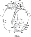
- the front edge 41A of the sleeve 40 has legs 48 which are radially straightened and together delimiting diametral dimensions greater than the internal diametral dimensions of the belt 12. This is best seen on the figure. figure 2B , where we see that the sleeve 40 has several radially straightened tabs 48 which retain the seal 20 by cooperating with the front edge 12A of the belt. In this case, it is therefore the front edge 12A of the belt which serves as the wedging edge.
- the seal 20 comprises three regularly distributed spacer tabs, namely two tabs 47 of the type shown in FIG. figure 4B and a tab 47 "of the type shown in figure 4D , as well as four wedging lugs 48.
- the tabs 48 serve as a stop opposing the displacement of the seal towards the rear relative to the belt.
- the seal 20 further comprises in this case a tube position key which, when the clamping device is disposed at the end 1A of the tube 1, determines the angular position of the clamping device relative to the tube.
- this tube position keyer comprises a tube position keyer tab 49 which projects radially outwardly of the seal and which is configured to engage in a slot formed at the end. of the tube.
- the end 1A of the tube has a slot 3 which, in this case, comprises a first slot part 3A forming a notch on the edge 1'A of the tube and a second part 3B forming a shaped window substantially in Y, this window having in this case a closed contour.
- the tube position keying tab 49 engages in the notch 3A and therefore makes it possible to angularly wedge the collar relative to the tube.
- this tube position coding tab 49 is folded backwards from the front edge of the sleeve 40. Its free end 49A is itself folded forward by being clamped on itself.
- the tube position keying tab 49 can also, by its part folded against the sleeve 30, contribute to the wedging of the front edge of the sleeve 30 relative to the sleeve 40. It can also, when its free end 49A is radially straightened , contribute to the bracing to keep the seal away from the belt 12 of the collar.
- the seal 20 also includes an anti-extraction tab 49 '.
- this tab 49 ' is formed by an extension of the rear edge 41B of the sleeve 40 folded forward on the outside towards the front and the free end 49'A of which is slightly straightened.
- this tab 49 ′ projects into a part of the slot 3B of the tube 3.
- the geometries of this slot part and of the tab 49' are such that the tab cooperates with the slot to oppose forward extraction of the seal relative to the tube.
- This tab 49 ′ also performs a function of keying the position of the tube, by angularly wedging the seal relative to the tube 1.
- the end 1A of the tube 1 is provided with the slot 3, so that, when the clamp is tightened, the diameter of the end 1A can be reduced by reducing the width of the slot.
- this slot is bridged on the inside by a solid part of the seal 20.
- Part 3B of the slot 3 forms a window with which the anti-extraction tab 49 'cooperates.
- the spacer tab which has been described (tabs 47, 47 'and 47 ", or even 49) is located on the front edge of the seal, so as not to obstruct the engagement of the end 1A of the tube. 1 between the belt 12 and the seal 20.
- the strip forming the first sleeve 30 is formed from a mica-based material. It is for example a material comprising mica and a silicone-type binder. For example, it may be a material of the type known under the trademark Cogemica Hi-temp® resistant to high temperatures and comprising, by weight, 90% of mica or more and 10% of binder or less.
- the strip forming the second sleeve 40 can be made of metal, in particular stainless steel. We have chosen here to place the metal sleeve inside the other sleeve, because it is the metal sleeve which carries, in one piece with it, the clamping tabs of the other sleeve, these tabs being folded back. outwards.
- the arrangement could be reversed, by placing the metal sleeve on the outside, while achieving suitable retention of the two sleeves with respect to each other.
- the outer sleeve can of course carry the spacer lugs and the seal and / or tube polarizer.
- the figure 6 shows an alternative embodiment which differs only from that which has just been described by the conformation of the slot formed at the end 1A of the tube 1 and, consequently, by the conformation of the lugs which prevent the position of the tube and anti- extraction carried by the seal 20 and, more precisely, by the sleeve 40.
- the slot 3 'formed at the end of the tube 1A comprises two elementary axial slot sections, in particular a front elementary slot section 3'A open on the front edge 1'A of the tube, and a closed elementary slot section 3'B, which forms a window 3'B and which is located at the rear of this slot 3'A and slightly angularly offset with respect to it.
- the sleeve 40 for its part, has a tube position keying tab 149 which is folded back towards the outside of this sleeve 40 and is dimensioned to be able to engage in the open slot portion 3'A of the tube.
- This sleeve 40 also has an anti-extraction tab 149 'folded forward from the rear edge of this sleeve and slightly angularly offset with respect to the tab 149, and whose conformation allows it to engage in the portion of closed slot 3'B to oppose forward extraction of the seal with respect to tube 1.
- the collar 10 is of the open type, which means that the ends of the belt 12 are folded back radially to form tightening tabs 16A and 16B which are able to be displaced with respect to one another. another to tighten the collar.
- these clamping tabs cooperate with a clamping rod 18 formed in this case by the shank of a screw comprising a head 18A which is retained behind the clamping tabs and a nut 18B retained behind the 'Another clamping tab, possibly via spacers 19.
- the rear of a clamping tab is the side of this tab which is opposite to the other clamping tab.
- a slot 15 of the collar is thus formed between the clamping tabs 16A and 16B. The angular positioning of the seal 20 with respect to the collar makes it possible to prevent the ends of the bands in which the sleeves are formed from being located in line with this slot.
- the collar has several series of windows 14 arranged symmetrically with respect to a radial median plane of the collar perpendicular to its axis A. This makes it possible to ensure that the collar can be positioned indifferently in one or the other. direction with respect to this radial median plane (that is to say that its rear edge takes the place of its front edge and vice versa) while allowing correct positioning of the seal in the collar.
Abstract
Le joint d'étanchéité (20) comprend un premier et un deuxième manchon coaxiaux (30, 40), disposés l'un autour de l'autre en étant retenus l'un par rapport à l'autre. Chaque manchon est formé par une bande enroulée sur elle-même (32, 42) dont les extrémités sont configurées pour coopérer entre-elles via un agencement d'étanchéité (34, 44) en permettant une réduction du diamètre du manchon. Les agencements d'étanchéité des deux manchons sont décalés angulairement. Le dispositif de serrage comprend un collier de serrage avec une ceinture à l'intérieur de laquelle est disposé le joint d'étanchéité (20) en étant retenu axialement par rapport au collier.The seal (20) includes a first and a second coaxial sleeve (30, 40), disposed around each other by being retained relative to each other. Each sleeve is formed by a strip wound on itself (32, 42) whose ends are configured to cooperate with one another via a sealing arrangement (34, 44) allowing a reduction in the diameter of the sleeve. The sealing arrangements of the two sleeves are angularly offset. The clamping device comprises a clamp with a belt inside which the seal (20) is disposed while being retained axially with respect to the clamp.
Description
Le présent exposé se rapporte à un joint d'étanchéité, ainsi qu'à un dispositif de serrage et à un ensemble de serrage comprenant un tel joint d'étanchéité.The present disclosure relates to a seal, as well as to a clamping device and to a clamping assembly comprising such a seal.
On connait des joints d'étanchéité de forme annulaire, réalisés par un anneau fermé. Pour réaliser leur fonction d'étanchéité, ces joints d'étanchéité doivent être comprimés et doivent donc être formés dans des matériaux permettant une telle compression tout en présentant les qualités requises pour résister aux conditions de l'environnement dans lequel est placé le joint d'étanchéité, par exemple en termes de température, de pression, ou de variation de ces paramètres. De plus, généralement, pour de tels joints d'étanchéité fermés, la différence entre le diamètre du joint d'étanchéité à l'état libre et le diamètre du joint d'étanchéité à l'état serré, après compression, est en général faible. Ainsi, ces joints d'étanchéité de type fermé ne conviennent pas à certaines applications.Annular seals are known, produced by a closed ring. To achieve their sealing function, these seals must be compressed and must therefore be formed from materials allowing such compression while having the qualities required to withstand the conditions of the environment in which the seal is placed. tightness, for example in terms of temperature, pressure, or variation of these parameters. In addition, generally, for such closed seals, the difference between the diameter of the seal in the free state and the diameter of the seal in the clamped state, after compression, is generally small. . Thus, these closed type gaskets are not suitable for some applications.
On connait par ailleurs, par exemple par les brevets
On connait par ailleurs des joints d'étanchéité de type ouvert, en particulier du type réalisé par une bande enroulée sur elle-même et dont les extrémités coopèrent entre elles par un agencement d'étanchéité. Un tel joint d'étanchéité est par exemple divulgué par le document
Pour certaines applications, il existe un besoin pour améliorer les joints d'étanchéité de type ouvert existants. En effet, l'ouverture du joint d'étanchéité, c'est-à-dire la jonction entre les extrémités de la bande dans laquelle il est formé, peut présenter une zone de faiblesse en matière d'étanchéité, malgré le fait que les extrémités en question coopèrent entre elles par un agencement d'étanchéité. De plus, selon le matériau dans lequel il est formé, le joint d'étanchéité peut présenter un effet ressort c'est-à-dire que la bande dans laquelle il est formé peut avoir tendance à se dérouler ce qui, dans certaines applications, peut compliquer la manutention, le stockage et le montage.For some applications, there is a need to improve existing open type seals. Indeed, the opening of the seal, that is to say the junction between the ends of the strip in which it is formed, may present a zone of weakness in terms of sealing, despite the fact that the the ends in question cooperate with each other by a sealing arrangement. In addition, depending on the material in which it is formed, the seal may have a spring effect, i.e. the strip in which it is formed may have a tendency to unroll which, in certain applications, can complicate handling, storage and assembly.
L'exposé vise à remédier au moins substantiellement aux inconvénients précités.The disclosure aims to remedy at least substantially the aforementioned drawbacks.
Ainsi, l'exposé se rapporte à un joint d'étanchéité comprenant un premier et un deuxième manchon coaxiaux disposés l'un autour de l'autre en étant retenus l'un par rapport à l'autre, chaque manchon étant formé par une bande enroulée sur elle-même dont les extrémités sont configurées pour coopérer entre elles via un agencement d'étanchéité en permettant une réduction du diamètre du manchon, les agencements d'étanchéité des deux manchons étant décalés angulairement.Thus, the disclosure relates to a seal comprising a first and a second coaxial sleeve arranged around each other while being retained with respect to each other, each sleeve being formed by a strip wound on itself, the ends of which are configured to cooperate with each other via a sealing arrangement allowing a reduction in the diameter of the sleeve, the sealing arrangements of the two sleeves being angularly offset.
Du fait du décalage angulaire des agencements d'étanchéité des deux manchons, l'agencement d'étanchéité de chaque manchon est "ponté" par l'autre manchon. Ainsi, l'agencement d'étanchéité de chaque manchon est recouvert radialement, soit du côté extérieur, soit du côté intérieur, par la bande dans laquelle est formé l'autre manchon. De plus, les manchons sont retenus l'un par rapport à l'autre, ce qui signifie qu'ils se maintiennent mutuellement. En d'autres termes, la présence de chaque manchon tend à s'opposer à ce que l'autre manchon n'ait tendance à se dérouler ou à ne pas conserver sa forme souhaitée.Due to the angular offset of the sealing arrangements of the two sleeves, the sealing arrangement of each sleeve is "bridged" by the other sleeve. Thus, the sealing arrangement of each sleeve is radially covered, either on the outside or on the inside, by the strip in which the other sleeve is formed. In addition, the sleeves are retained with respect to each other, which means that they hold each other. In other words, the presence of each sleeve tends to prevent the other sleeve from tending to unwind or not to retain its desired shape.
Cependant, le joint d'étanchéité conserve l'avantage des joints d'étanchéité de type ouvert en ce qu'il est simple à fabriquer pour différents diamètres en ajustant la longueur des bandes dans laquelle sont formés les deux manchons et en ce qu'il réalise sa fonction d'étanchéité par une réduction de son diamètre faisant se rapprocher des extrémités respectives des deux manchons.However, the gasket retains the advantage of open type gaskets in that it is simple to manufacture for different diameters by adjusting the length of the bands in which the two sleeves are formed and in that it performs its sealing function by reducing its diameter bringing the respective ends of the two sleeves closer together.
Optionnellement, les deux manchons sont formés dans des matériaux différents, la bande formant le premier manchon étant optionnellement formée dans un matériau à base de mica et la bande formant le deuxième manchon étant optionnellement métallique.Optionally, the two sleeves are formed from different materials, the strip forming the first sleeve being optionally formed from a mica-based material and the strip forming the second sleeve being optionally metallic.
Optionnellement, la bande formant au moins l'un des premier et deuxième manchons a naturellement tendance à se dérouler et est maintenue enroulée par l'autre manchon.Optionally, the strip forming at least one of the first and second sleeves naturally tends to unwind and is kept rolled up by the other sleeve.
Optionnellement, l'agencement d'étanchéité d'au moins l'un des premier et deuxième manchons comprend une conformation d'engagement mâle/femelle.Optionally, the sealing arrangement of at least one of the first and second sleeves comprises a male / female engagement conformation.
Optionnellement, au moins l'un des premier et deuxième manchons présente au moins une patte de coincement, sous laquelle un bord de l'autre manchon est coincé.Optionally, at least one of the first and second sleeves has at least one wedging tab, under which one edge of the other sleeve is wedged.
Le présent exposé concerne également un dispositif de serrage comprenant un collier qui présente une ceinture apte à être serrée par réduction de son diamètre, et un joint d'étanchéité selon le présent exposé, dans lequel le joint d'étanchéité est disposé à l'intérieur de la ceinture en étant retenu axialement par rapport au collier et en étant configuré pour dégager un espace annulaire permettant l'insertion d'un objet annulaire entre le joint d'étanchéité et la ceinture.The present disclosure also relates to a tightening device comprising a collar which has a belt capable of being tightened by reducing its diameter, and a seal according to the present disclosure, in which the seal is disposed inside. of the belt by being retained axially relative to the collar and by being configured to release an annular space allowing the insertion of an annular object between the seal and the belt.
Ainsi, ce dispositif de serrage permet d'utiliser un joint d'étanchéité fonctionnant comme un joint d'étanchéité de type ouvert pré-monté dans un collier. Lorsque le joint d'étanchéité est en place dans le collier, l'espace annulaire permet l'insertion d'un objet annulaire tel que l'extrémité d'un tube entre la ceinture et le joint d'étanchéité. Ainsi, le dispositif de serrage est pré-monté sur cet objet annulaire, qui peut recevoir un autre objet annulaire, en particulier un tube intérieur qui sera emmanché dans cet ensemble, en particulier en étant emmanché dans le joint d'étanchéité de sorte que ce joint d'étanchéité se trouve entre les deux objets emmanchés l'un dans l'autre pour assurer leur liaison étanche une fois que le collier est serré autour de l'emmanchement ainsi réalisé.Thus, this clamping device makes it possible to use a seal functioning as an open type seal pre-mounted in a collar. When the seal is in place in the collar, the annular space allows the insertion of an annular object such as the end of a tube between the belt and the seal. Thus, the clamping device is pre-mounted on this annular object, which can receive another annular object, in particular an inner tube which will be fitted in this assembly, in particular by being fitted in the seal so that this seal is located between the two objects fitted into one another to ensure their tight connection once the collar is tightened around the fitting thus produced.
Optionnellement, l'un des éléments comprenant le collier et le joint d'étanchéité comprend au moins une entretoise ménageant l'espace annulaire entre le joint d'étanchéité et la ceinture, l'entretoise comprenant optionnellement une patte d'entretoisement portée par le joint d'étanchéité, en saillie radiale vers l'extérieur.Optionally, one of the elements comprising the collar and the seal comprises at least one spacer providing the annular space between the seal and the belt, the spacer optionally comprising a spacer lug carried by the seal. sealing, projecting radially outwards.
Optionnellement, le dispositif comprend un détrompeur angulaire de joint d'étanchéité configuré pour déterminer une position angulaire du joint d'étanchéité par rapport au collier.Optionally, the device comprises an angular seal keying device configured to determine an angular position of the seal relative to the collar.
Optionnellement, l'un des éléments formés par la ceinture et le joint d'étanchéité présente un bord de calage et l'autre élément présente une saillie de calage apte à coopérer avec le bord de calage pour retenir le joint d'étanchéité vis-à-vis d'un déplacement par rapport au collier.Optionally, one of the elements formed by the belt and the seal has a wedging edge and the other element has a wedging projection adapted to cooperate with the wedging edge to retain the seal vis-à-vis. -vis of a displacement relative to the collar.
Optionnellement, le joint d'étanchéité présente un bord avant pourvu d'au moins une butée configurée pour coopérer avec le bord avant de la ceinture pour retenir le joint d'étanchéité vis-à-vis d'un déplacement dans au moins une direction par rapport à la ceinture, la butée comprenant optionnellement une patte redressée vers l'extérieur.Optionally, the seal has a front edge provided with at least one stopper configured to cooperate with the front edge of the belt to retain the seal against movement in at least one direction by. relative to the belt, the stop optionally comprising a tab which is straightened outwards.
Optionnellement, la ceinture présente une fenêtre dont le bord forme un bord de calage, et le joint d'étanchéité présente une patte de retenue redressée dans cette fenêtre.Optionally, the belt has a window, the edge of which forms a wedging edge, and the seal has a retaining tab straightened in this window.
Optionnellement, le collier présente des pattes de serrage, relevées radialement par rapport à la ceinture et aptes à être déplacées l'une par rapport à l'autre pour serrer le collier.Optionally, the collar has tightening tabs, raised radially relative to the belt and able to be moved relative to one another to tighten the collar.
Le présent exposé concerne encore un ensemble de serrage de tube, comprenant un dispositif de serrage selon le présent exposé et un tube dont l'extrémité est apte à être insérée entre le joint d'étanchéité et la ceinture.The present disclosure also relates to a tube clamping assembly, comprising a clamping device according to the present disclosure and a tube whose end is adapted to be inserted between the seal and the belt.
Optionnellement, l'ensemble comprend un détrompeur de position de tube déterminant une position angulaire du tube par rapport au moins l'un des éléments comprenant le joint d'étanchéité et le collier.Optionally, the assembly comprises a tube position key determining an angular position of the tube relative to at least one of the elements comprising the seal and the collar.
Optionnellement, le joint d'étanchéité présente une patte détrompeur de position de tube qui fait radialement saillie vers l'extérieur du joint d'étanchéité et qui est configurée pour être engagée dans une fente formée à l'extrémité du tube.Optionally, the seal has a tube position keying tab which projects radially outwardly from the seal and which is configured to engage in a slot formed at the end of the tube.
Optionnellement, le joint d'étanchéité comprend une patte anti-extraction, configurée pour coopérer avec une fenêtre du tube pour s'opposer à l'extraction du joint d'étanchéité hors du tube.Optionally, the seal comprises an anti-extraction tab, configured to cooperate with a window of the tube to oppose the extraction of the seal from the tube.
L'exposé sera bien compris et son objet apparaitra mieux à la lecture de la description détaillée qui suit, d'un mode de réalisation et de ses variantes, représentés à titre d'exemples non limitatifs.The description will be well understood and its object will appear more clearly on reading the following detailed description of an embodiment and its variants, shown by way of non-limiting examples.
-
[
Fig. 1 ] Lafigure 1 est une vue en perspective éclatée montrant un ensemble de serrage de tube comprenant un joint d'étanchéité selon le présent exposé et un dispositif de serrage selon le présent exposé.[Fig. 1 ] Thefigure 1 is an exploded perspective view showing a tube clamp assembly including a seal according to the present disclosure and a clamp device according to the present disclosure. -
[
Fig. 2A ] Lafigure 2A est une vue en perspective d'un dispositif de serrage selon le présent exposé, selon un premier angle de vue.[Fig. 2A ] Thefigure 2A is a perspective view of a clamping device according to the present disclosure, from a first viewing angle. -
[
Fig. 2B ] Lafigure 2B est une vue en perspective du dispositif de serrage lafigure 2A selon un autre angle de vue.[Fig. 2B ] Thefigure 2B is a perspective view of the clamping devicefigure 2A from another angle of view. -
[
Fig. 3 ] Lafigure 3 montre le dispositif de serrage en perspective, le joint d'étanchéité étant représenté séparé du collier.[Fig. 3 ] Thefigure 3 shows the clamp in perspective, the seal being shown separate from the collar. -
[
Fig. 4A ] Lafigure 4A montre en perspective l'un des manchons du joint d'étanchéité du dispositif de serrage des figures précédentes.[Fig. 4A ] Thefigure 4A shows in perspective one of the sleeves of the seal of the clamping device of the preceding figures. -
[
Fig. 4B-4D ] Lesfigures 4B à 4D montrent en coupe axiale partielle une partie du joint d'étanchéité.[Fig. 4B-4D ] Thefigures 4B to 4D show part of the seal in partial axial section. -
[
Fig. 5 ] Lafigure 5 montre en perspective le dispositif de serrage selon le présent exposé monté à l'extrémité d'un tube externe, avant emmanchement d'un tube interne dans le tube externe.[Fig. 5 ] Thefigure 5 shows in perspective the clamping device according to the present disclosure mounted at the end of an outer tube, before fitting an inner tube into the outer tube. -
[
Fig. 6 ] Lafigure 6 est une vue analogue à lafigure 1 pour une variante de réalisation.[Fig. 6 ] Thefigure 6 is a view analogous tofigure 1 for an alternative embodiment.
L'ensemble représenté sur la
S'agissant du joint d'étanchéité 20, chacun des premier et deuxième manchons 30 et 40 est formé par une bande, respectivement 32 et 42, qui est enroulée sur elle-même et dont les extrémités sont configurées pour coopérer entre elles via un agencement d'étanchéité.Regarding the
Ainsi, les extrémités 32A et 32B de la bande 32 coopèrent entre elles via un agencement d'étanchéité 34 qui comprend en l'espèce un engagement mâle/femelle. Dans l'exemple, cet agencement d'étanchéité comprend une encoche 34A formée à l'extrémité 32A et délimitée entre des bords de contact 34'A formés en l'espèce par des bords internes de pattes 35A subsistant de part et d'autre de l'encoche 34A.Thus, the
L'agencement d'étanchéité 34 comprend également une languette 34B formée à l'extrémité 32B. On voit que, sur une partie de la longueur de l'encoche, cette longueur étant mesurée circonférentiellement, la largeur de cette encoche (mesurée parallèlement à l'axe A) varie. Plus précisément, dans la partie de l'encoche proche des extrémités libres des pattes 35A, la largeur de l'encoche augmente à mesure que l'on se rapproche de ces extrémités libres, c'est-à-dire à mesure que l'on s'éloigne du fond de l'encoche. De même, dans une partie de la longueur de la languette 34B, la largeur de cette languette augmente à mesure que l'on s'éloigne de son extrémité libre. Ainsi, lorsque la languette pénètre plus profondément dans l'encoche à mesure que le diamètre du manchon 30 diminue lors du serrage du collier, la pression de contact entre les bords de la languette et les bords de contact 34'A augmente de manière à réaliser un contact étanche. En l'espèce, la partie terminale de la languette et la partie de fond de l'encoche ont en revanche une largeur constante et égale, ce qui facilite l'avancée de la languette dans l'encoche.The sealing
Le deuxième manchon 40 est formé à partir d'une bande 42 enroulée sur elle-même et dont les extrémités, respectivement 42A et 42B coopèrent entre elles par un agencement d'étanchéité 44. En l'espèce, cet agencement d'étanchéité 44 comprend une conformation d'engagement mâle/femelle. Plus précisément, l'extrémité 42A comprend une encoche 44A délimitée entre deux pattes 45A, et l'extrémité 42B comprend une languette 44B qui, lorsque le diamètre du manchon 40 diminue, pénètre dans l'encoche 44A. En l'espèce, cette languette est délimitée latéralement par deux fentes 45B dans lesquelles pénètrent les pattes 45A à mesure que la languette 44B pénètre dans l'encoche 44A. Ces fentes 45B sont elles-mêmes bordées latéralement par des pattes 45C. Dans ce cas, l'agencement d'étanchéité forme en quelque sorte une chicane considérée axialement, la zone de contact entre les extrémités 42A et 42B s'effectuant entre les pattes 45C et 45A et la languette 44B.The
Bien entendu, d'autres conformations d'agencement mâle/femelle seraient possibles. Ainsi, l'agencement d'étanchéité 44 du manchon 40 pourrait avoir la géométrie décrite ci-dessus pour l'agencement d'étanchéité 34 du manchon 30 et réciproquement. D'autres agencements d'étanchéité peuvent être prévus, qu'ils soient comme en l'espèce prévus directement sur la bande 32 ou 42, en une pièce avec elle, ou bien rapportés, par exemple en un matériau davantage déformable. L'étanchéité peut également être obtenue par un effet de chicane sans nécessairement mettre en œuvre les contraintes de contact évoquées plus haut. A l'inverse, pour au moins l'un des manchons, l'étanchéité peut être liée aux contraintes de contacts évoquées plus haut, en particulier au sein d'un engagement mâle/femelle, ces contraintes pouvant aller jusqu'à provoquer des déformations, plastiques ou élastiques.Of course, other conformations of male / female arrangement would be possible. Thus, the sealing
En se référant également à la
Au sens du présent exposé, on qualifiera de "interne" les éléments tournés vers l'axe A du joint d'étanchéité (qui correspond à l'axe A de la ceinture du collier et des tubes lorsque ces éléments sont assemblés), tandis que les éléments externes sont ceux qui sont opposés à cet axe.For the purposes of the present disclosure, the elements facing the axis A of the seal (which corresponds to the axis A of the belt of the collar and of the tubes when these elements are assembled) will be qualified as "internal", while the external elements are those which are opposed to this axis.
Par ailleurs, les qualificatifs « avant » et « arrière » sont entendus par rapport au sens d'emmanchement des tubes. Ainsi, l'extrémité 1'A du tube 1 est son extrémité avant à partir de laquelle il est emmanché sur le tube 2. Les bords avant 31A et 41A des manchons 30 et 40 sont ceux qui, lorsque le joint d'étanchéité est disposé autour de l'extrémité 1A du tube 1, sont les plus proches de l'extrémité libre 1'A de ce tube, par opposition aux bords arrière 31B et 41B de ces manchons.Furthermore, the qualifiers “front” and “rear” are understood in relation to the direction of fitting of the tubes. Thus, the end 1'A of the
Qu'il soit interne ou externe, l'un des manchons peut avoir naturellement tendance à se dérouler pour procurer un effet élastique. Ceci peut être le cas lorsque le manchon en question est réalisé en métal, comme c'est par exemple le cas du deuxième manchon 40, et peut également être le cas d'un manchon réalisé dans un matériau à base de mica, comme c'est par exemple le cas du manchon 30. Cependant, le fait que les deux manchons soient retenus l'un par rapport à l'autre limite cette tendance. En effet, le premier manchon 30, notamment en raison du pontage qu'il opère dans la région de la jonction entre les extrémités 42A et 42B du deuxième manchon 40, tend à s'opposer à l'éloignement de ces extrémités 42A et 42B et donc au déroulement de la bande 42 dans laquelle est formé ce deuxième manchon 40. Réciproquement, le deuxième manchon 40, notamment en raison du pontage qu'il opère dans la région de la jonction entre les extrémités 32A et 32B du premier manchon 30, tend à s'opposer à l'éloignement de ces extrémités 32A et 32B et donc au déroulement de la bande 32 dans laquelle est formé ce premier manchon 30.Whether internal or external, one of the sleeves may naturally tend to unwind to provide an elastic effect. This may be the case when the sleeve in question is made of metal, as is for example the case of the
En l'espèce, comme on le verra dans la suite, les deux manchons peuvent être retenus l'un par rapport à l'autre par coincement. Même si les deux manchons présentent chacun une certaine élasticité leur conférant une tendance à se dérouler, les contraintes de coincement (ou, généralement, les contraintes dues au fait qu'ils sont retenus l'un par rapport à l'autre) peuvent être suffisantes pour, en pontant la jonction des extrémités de chaque manchon par l'autre manchon, s'opposer à ce déroulement. Le coincement, qui peut être réalisé sous la forme d'un pincement, présente l'avantage de réaliser la retenue souhaitée tout en permettant de légers déplacements des deux manchons l'un par rapport à l'autre, selon leurs directions circonférentielles, afin de permettre les rapprochements des extrémités des bandes 32 et 42 permettant la réduction du diamètre du joint d'étanchéité sous l'effet du serrage du collier.In this case, as will be seen below, the two sleeves can be retained with respect to each other by wedging. Even if the two sleeves each have a certain elasticity giving them a tendency to unwind, the jamming stresses (or, generally, the stresses due to the fact that they are retained with respect to each other) may be sufficient. for, by bridging the junction of the ends of each sleeve by the other sleeve, to oppose this unwinding. The wedging, which can be achieved in the form of a pinch, has the advantage of achieving the desired retention while allowing slight movements of the two sleeves relative to each other, in their circumferential directions, in order to allow the ends of the
En l'espèce, comme indiqué plus haut, les deux manchons sont retenus l'un par rapport à l'autre par coincement. Ainsi, au moins l'un des premier et deuxième manchons 30 et 40 présente au moins une patte de coincement 46, sous laquelle un bord de l'autre manchon, en particulier un bord perpendiculaire à l'axe A du manchon, est coincé. En l'espèce le deuxième manchon 40, présente des pattes de coincement 46 sous lesquelles les bords du premier manchon 30 sont coincés. En l'espèce, les pattes de coincement 46 sont prévues sur les bords avant 41A et arrière 41B du manchon 40, de manière à pouvoir coincer les bords avant et arrière 31A et 31B du manchon 30. En l'espèce, dans la mesure où le manchon 40 est disposé à l'intérieur du manchon 30, les pattes de coincement sont formées par des extensions repliées du côté de la face externe du manchon 40. Pour l'assemblage des deux manchons, ces pattes de coincement peuvent initialement être redressées radialement, puis, une fois que le manchon 30 est disposé autour du manchon 40, être repliées contre la face externe de ce manchon pour venir pincer les bords du manchon 30.In this case, as indicated above, the two sleeves are retained relative to each other by wedging. Thus, at least one of the first and
Sur les
Par ailleurs, l'extrémité libre de la languette 34B est elle-même coincée sous des pattes 46' découpées dans la bande 42 et légèrement redressées.Furthermore, the free end of the
En l'espèce, les pattes de coincement 46, 49 et 49' sont réparties sur chacun des bords avant et arrière du manchon 40. On peut par exemple prévoir entre trois et quinze pattes de coincement, par exemple entre quatre et dix pattes de coincement sur l'un et/ou l'autre des bords avant et arrière. Bien entendu, le nombre de pattes de coincement pourra dépendre du diamètre du manchon.In this case, the jamming
On peut également prévoir qu'il y ait davantage de pattes de coincement sur l'un des bords du manchon, par exemple le bord arrière, par exemple parce que l'autre bord comporterait d'autres pattes ou conformations réalisant d'autres fonctions, ainsi qu'il sera exposé dans la suite à titre d'exemple.Provision can also be made for there to be more wedging tabs on one of the edges of the sleeve, for example the rear edge, for example because the other edge would have other tabs or conformations performing other functions, as will be explained below by way of example.
En l'espèce, les pattes de coincement sont réalisées dans le manchon interne et repliées vers l'extérieur, de sorte que la périphérie interne du joint d'étanchéité est lisse.In this case, the wedging tabs are made in the internal sleeve and folded outwards, so that the internal periphery of the seal is smooth.
Le dispositif de serrage selon le présent exposé comprend un collier de serrage 10 et le joint d'étanchéité qui vient d'être décrit. Comme on le voit sur les
Comme on le voit mieux sur les
L'espace annulaire 50 peut être ménagé grâce à une entretoise qui s'étend entre le joint d'étanchéité et la ceinture. En l'espèce, cette entretoise comprend au moins une patte d'entretoisement 47 qui est portée par le joint d'étanchéité 20 et qui est en saillie radiale vers l'extérieur. Plus précisément, en l'espèce, la patte d'entretoisement 47 est portée par le manchon 40 et, comme les pattes de coincement 46, 49 et 49', elle est réalisée par une extension de ce manchon repliée vers l'extérieur.The
Comme on le voit sur les
Sur la
Sur la
Optionnellement, le dispositif comprend un détrompeur angulaire de joint d'étanchéité configuré pour déterminer une position angulaire du joint d'étanchéité par rapport au collier. En l'espèce, ce détrompeur angulaire de joint d'étanchéité met à contribution la patte 47 représentée sur les
En l'espèce, ce détrompeur angulaire est formé par l'extrémité de la patte d'entretoisement 47. De la même manière, on pourrait prévoir qu'un tel détrompeur angulaire soit formé par l'extrémité d'une patte ayant une autre fonction, en particulier une patte de coincement disposée et étendue en conséquence, coopérant éventuellement avec une encoche du bord avant du tube 1 pour réaliser en outre une fonction de détrompeur de position de tube qui sera décrite plus loin.In this case, this angular polarizer is formed by the end of the
Par ailleurs, ce détrompeur angulaire s'oppose à un déplacement du joint d'étanchéité par rapport au collier non seulement, comme exposé, dans le sens circonférentiel mais également dans le sens axial, parallèle à l'axe A. Ainsi, le bord 14A de la fenêtre 14 forme un bord de calage coopérant avec la saillie de calage réalisée par la portion de patte terminale 47C pour retenir le joint d'étanchéité 20 vis-à-vis d'un déplacement axial par rapport au collier 10.Furthermore, this angular polarizer opposes a displacement of the seal relative to the collar not only, as explained, in the circumferential direction but also in the axial direction, parallel to the axis A. Thus, the
Cependant, dans l'exemple représenté, le bord avant du joint d'étanchéité présente également d'autres saillies de calage. En l'espèce, comme on le voit notamment sur la
Dans l'exemple représenté, le joint d'étanchéité 20 comprend trois pattes d'entretoisement régulièrement réparties, à savoir deux pattes 47 du type représenté sur la
Le joint d'étanchéité 20 comprend en l'espèce en outre un détrompeur de position de tube qui, lorsque le dispositif de serrage est disposé à l'extrémité 1A du tube 1, détermine la position angulaire du dispositif de serrage par rapport au tube. En l'espèce, ce détrompeur de position de tube comprend une patte de détrompeur de position de tube 49 qui fait radialement saillie vers l'extérieur du joint d'étanchéité et qui est configurée pour s'engager dans une fente formée à l'extrémité du tube. En se reportant à la
Optionnellement, le joint d'étanchéité 20 comprend également une patte anti-extraction 49'. En l'espèce, cette patte 49' est formée par un prolongement du bord arrière 41B du manchon 40 replié vers l'avant à l'extérieur vers l'avant et dont l'extrémité libre 49'A est légèrement redressée. On voit sur la
En l'espèce, l'extrémité 1A du tube 1 est pourvue de la fente 3, de sorte que, lors du serrage du collier, le diamètre de l'extrémité 1A peut être réduit par réduction de la largeur de la fente.In this case, the
Cependant, cette fente est pontée du côté intérieur par une partie pleine du joint d'étanchéité 20. La partie 3B de la fente 3 forme une fenêtre avec laquelle coopère la patte anti-extraction 49'.However, this slot is bridged on the inside by a solid part of the
La patte d'entretoisement qui a été décrite (pattes 47, 47' et 47", voire 49) est située sur le bord avant du joint d'étanchéité, pour ne pas faire obstacle à l'engagement de l'extrémité 1A du tube 1 entre la ceinture 12 et le joint 20. Cependant, la patte 49' peut également réaliser une fonction d'entretoisement maintenant le joint d'étanchéité à distance de la ceinture, à condition de pouvoir s'effacer lors de l'emmanchement de l'extrémité 1A du tube 1 dans le dispositif de serrage.The spacer tab which has been described (
Par exemple, la bande formant le premier manchon 30 est formée dans un matériau à base de mica. Il s'agit par exemple d'un matériau comprenant du mica et un liant de type silicone. Par exemple, il peut s'agir d'un matériau de type connu sous la marque Cogemica Hi-temp® résistant à des températures élevées et comprenant, en masse, 90 % de mica ou davantage et 10 % de liant ou moins. Par exemple, la bande formant le deuxième manchon 40 peut être réalisée en métal, en particulier un acier inoxydable. On a choisi ici de placer le manchon métallique à l'intérieur de l'autre manchon, car c'est le manchon métallique qui porte, en une seule pièce avec lui, les pattes de coincement de l'autre manchon, ces pattes étant repliées vers l'extérieur. On pourrait inverser la disposition, en plaçant le manchon métallique à l'extérieur, tout en réalisant une retenue adaptée des deux manchons l'un par rapport à l'autre. Dans ce cas, le manchon extérieur peut bien entendu porter les pattes d'entretoisement et de détrompeur de joint et/ou de tube.For example, the strip forming the
La
Dans l'exemple représenté, le collier 10 est de type ouvert, ce qui signifie que les extrémités de la ceinture 12 sont repliées radialement pour former des pattes de serrage 16A et 16B qui sont aptes à être déplacées l'une par rapport à l'autre pour serrer le collier. En l'espèce, ces pattes de serrage coopèrent avec une tige de serrage 18 formée en l'espèce par le fût d'une vis comprenant une tête 18A qui est retenue en arrière des pattes de serrage et un écrou 18B retenu en arrière de l'autre patte de serrage, éventuellement via des entretoises 19. Dans le cas précis des pattes de serrage 16A et 16B, l'arrière d'une patte de serrage est le côté de cette patte qui est opposé à l'autre patte de serrage. Une fente 15 du collier est ainsi ménagée entre les pattes de serrage 16A et 16B. Le positionnement angulaire du joint d'étanchéité 20 par rapport au collier permet d'éviter que les extrémités des bandes dans lesquelles sont formés les manchons ne soient situées au droit de cette fente.In the example shown, the
On remarque enfin que le collier présente plusieurs séries de fenêtres 14 disposées symétriquement par rapport à un plan radial médian du collier perpendiculaire à son axe A. Ceci permet de faire en sorte que le collier puisse être indifféremment disposé dans l'un ou l'autre sens par rapport à ce plan radial médian (c'est-à-dire que son bord arrière prend la place de son bord avant et réciproquement) tout en permettant un positionnement correct du joint d'étanchéité dans le collier.Finally, it is noted that the collar has several series of
Claims (16)
Applications Claiming Priority (1)
| Application Number | Priority Date | Filing Date | Title |
|---|---|---|---|
| FR1904668A FR3095683B1 (en) | 2019-05-03 | 2019-05-03 | Gasket and clamping device and assembly comprising such a gasket |
Publications (2)
| Publication Number | Publication Date |
|---|---|
| EP3734130A1 true EP3734130A1 (en) | 2020-11-04 |
| EP3734130B1 EP3734130B1 (en) | 2022-12-14 |
Family
ID=67742736
Family Applications (1)
| Application Number | Title | Priority Date | Filing Date |
|---|---|---|---|
| EP20171694.1A Active EP3734130B1 (en) | 2019-05-03 | 2020-04-28 | Tightening device comprising a sealing gasket and assembly comprising such a device |
Country Status (9)
| Country | Link |
|---|---|
| US (1) | US20200347968A1 (en) |
| EP (1) | EP3734130B1 (en) |
| JP (1) | JP2020183809A (en) |
| KR (1) | KR20200127896A (en) |
| CN (1) | CN111878648A (en) |
| BR (1) | BR102020008387A2 (en) |
| FR (1) | FR3095683B1 (en) |
| MX (1) | MX2020004613A (en) |
| RU (1) | RU2020115105A (en) |
Citations (7)
| Publication number | Priority date | Publication date | Assignee | Title |
|---|---|---|---|---|
| US4201407A (en) * | 1978-10-23 | 1980-05-06 | Maremont Corporation | Tubular assembly |
| US5588680A (en) * | 1994-12-20 | 1996-12-31 | Bks Company | Pipe lap joint with improved collapsible sealing zone |
| EP1181477A1 (en) | 1999-06-02 | 2002-02-27 | Etablissements CAILLAU | Device for sealed connection between two smooth tubes |
| US20030205899A1 (en) * | 2002-05-06 | 2003-11-06 | Bishop John P. | Coupling |
| US20060175837A1 (en) * | 2005-02-10 | 2006-08-10 | Breeze-Torca Products, Llc | Pipe clamp with gasketed center rib |
| EP2598785A1 (en) | 2010-07-27 | 2013-06-05 | Etablissements Caillau | Clamping system for connecting and preliminarily mounting a first and a second tube |
| EP3232107A1 (en) | 2016-04-12 | 2017-10-18 | Etablissements Caillau | Clamping device comprising a clamping collar and a sleeve |
Family Cites Families (5)
| Publication number | Priority date | Publication date | Assignee | Title |
|---|---|---|---|---|
| US4473246A (en) * | 1981-11-06 | 1984-09-25 | Michigan Tube Benders | Pipe coupling |
| GB0206804D0 (en) * | 2002-03-22 | 2002-05-01 | Tyco Electronics Raychem Gmbh | Adjustable insert for a duct or bulkhead opening |
| FR2884582B1 (en) * | 2005-04-13 | 2010-01-08 | Caillau Ets | DEVICE FOR THE SEALED COUPLING OF TWO SMOOTH TUBES |
| KR101703301B1 (en) * | 2009-07-24 | 2017-02-06 | 노마 유.에스. 홀딩 엘엘씨 | Band clamp with embossed gasket for slotted pipe lap joints |
| FR3057047B1 (en) * | 2016-10-04 | 2019-05-10 | Etablissements Caillau | CONTROLLED ANGULAR POSITION CLAMPING SYSTEM FOR CONNECTING TWO TUBES |
-
2019
- 2019-05-03 FR FR1904668A patent/FR3095683B1/en active Active
-
2020
- 2020-04-26 CN CN202010336819.0A patent/CN111878648A/en active Pending
- 2020-04-27 JP JP2020077972A patent/JP2020183809A/en active Pending
- 2020-04-28 BR BR102020008387-2A patent/BR102020008387A2/en not_active Application Discontinuation
- 2020-04-28 EP EP20171694.1A patent/EP3734130B1/en active Active
- 2020-04-29 US US16/861,313 patent/US20200347968A1/en not_active Abandoned
- 2020-04-29 KR KR1020200052715A patent/KR20200127896A/en unknown
- 2020-04-29 RU RU2020115105A patent/RU2020115105A/en unknown
- 2020-07-13 MX MX2020004613A patent/MX2020004613A/en unknown
Patent Citations (7)
| Publication number | Priority date | Publication date | Assignee | Title |
|---|---|---|---|---|
| US4201407A (en) * | 1978-10-23 | 1980-05-06 | Maremont Corporation | Tubular assembly |
| US5588680A (en) * | 1994-12-20 | 1996-12-31 | Bks Company | Pipe lap joint with improved collapsible sealing zone |
| EP1181477A1 (en) | 1999-06-02 | 2002-02-27 | Etablissements CAILLAU | Device for sealed connection between two smooth tubes |
| US20030205899A1 (en) * | 2002-05-06 | 2003-11-06 | Bishop John P. | Coupling |
| US20060175837A1 (en) * | 2005-02-10 | 2006-08-10 | Breeze-Torca Products, Llc | Pipe clamp with gasketed center rib |
| EP2598785A1 (en) | 2010-07-27 | 2013-06-05 | Etablissements Caillau | Clamping system for connecting and preliminarily mounting a first and a second tube |
| EP3232107A1 (en) | 2016-04-12 | 2017-10-18 | Etablissements Caillau | Clamping device comprising a clamping collar and a sleeve |
Also Published As
| Publication number | Publication date |
|---|---|
| FR3095683B1 (en) | 2022-12-09 |
| JP2020183809A (en) | 2020-11-12 |
| EP3734130B1 (en) | 2022-12-14 |
| US20200347968A1 (en) | 2020-11-05 |
| KR20200127896A (en) | 2020-11-11 |
| CN111878648A (en) | 2020-11-03 |
| RU2020115105A (en) | 2021-10-29 |
| FR3095683A1 (en) | 2020-11-06 |
| BR102020008387A2 (en) | 2021-01-12 |
| MX2020004613A (en) | 2020-11-04 |
Similar Documents
| Publication | Publication Date | Title |
|---|---|---|
| EP3217059B1 (en) | Tightening system comprising a collar and isolated pre-mounting clips | |
| EP1451498B1 (en) | Clamping system for the sealed connection of two tubes having support surfaces | |
| EP2017518B1 (en) | Tightening device with tightening collar and positioning element | |
| EP2598785B1 (en) | Clamping system for connecting and preliminarily mounting a first and a second tube | |
| EP3189261B1 (en) | System for coupling two tubes | |
| WO2008145919A2 (en) | Clamping device | |
| FR3057047A1 (en) | CONTROLLED ANGULAR POSITION CLAMPING SYSTEM FOR CONNECTING TWO TUBES | |
| FR2967230A1 (en) | ARTICULATED TIGHTENING NECKLACE | |
| WO2002016815A1 (en) | Coupling for connecting a tubular fitting to a pipe | |
| EP1807648A1 (en) | Segmented locking ring, and corresponding assembly and mounting method | |
| EP3670988B1 (en) | Clamping device comprising a belt and a sealing ring | |
| EP3561360B1 (en) | Tightening system with folding tabs for connecting tubes | |
| EP0280598B1 (en) | Hose clamp with an elasticity reserve | |
| EP1875116A1 (en) | Device for sealed coupling of two smooth tubes | |
| EP3734130B1 (en) | Tightening device comprising a sealing gasket and assembly comprising such a device | |
| EP3734129B1 (en) | Clamping device comprising a collar and a sealing gasket | |
| EP3910223A1 (en) | Clamping system comprising a collar and a pre-assembly clip | |
| EP1456573B1 (en) | Device for sealed coupling of two rigid tubes of same external diameter | |
| EP3795877B1 (en) | Clamping collar | |
| EP0581678A1 (en) | Radial clamping device for connecting a pipe to a pipe end | |
| EP3999766B1 (en) | Compact and demountable fluid connection device | |
| EP0807780B1 (en) | Device for sealingly connecting two flat pipes | |
| EP1131578B1 (en) | Connecting and bracing clip for two clamp fittings |
Legal Events
| Date | Code | Title | Description |
|---|---|---|---|
| PUAI | Public reference made under article 153(3) epc to a published international application that has entered the european phase |
Free format text: ORIGINAL CODE: 0009012 |
|
| STAA | Information on the status of an ep patent application or granted ep patent |
Free format text: STATUS: THE APPLICATION HAS BEEN PUBLISHED |
|
| AK | Designated contracting states |
Kind code of ref document: A1 Designated state(s): AL AT BE BG CH CY CZ DE DK EE ES FI FR GB GR HR HU IE IS IT LI LT LU LV MC MK MT NL NO PL PT RO RS SE SI SK SM TR |
|
| AX | Request for extension of the european patent |
Extension state: BA ME |
|
| STAA | Information on the status of an ep patent application or granted ep patent |
Free format text: STATUS: REQUEST FOR EXAMINATION WAS MADE |
|
| 17P | Request for examination filed |
Effective date: 20210409 |
|
| RBV | Designated contracting states (corrected) |
Designated state(s): AL AT BE BG CH CY CZ DE DK EE ES FI FR GB GR HR HU IE IS IT LI LT LU LV MC MK MT NL NO PL PT RO RS SE SI SK SM TR |
|
| GRAP | Despatch of communication of intention to grant a patent |
Free format text: ORIGINAL CODE: EPIDOSNIGR1 |
|
| STAA | Information on the status of an ep patent application or granted ep patent |
Free format text: STATUS: GRANT OF PATENT IS INTENDED |
|
| INTG | Intention to grant announced |
Effective date: 20220704 |
|
| GRAS | Grant fee paid |
Free format text: ORIGINAL CODE: EPIDOSNIGR3 |
|
| GRAA | (expected) grant |
Free format text: ORIGINAL CODE: 0009210 |
|
| STAA | Information on the status of an ep patent application or granted ep patent |
Free format text: STATUS: THE PATENT HAS BEEN GRANTED |
|
| AK | Designated contracting states |
Kind code of ref document: B1 Designated state(s): AL AT BE BG CH CY CZ DE DK EE ES FI FR GB GR HR HU IE IS IT LI LT LU LV MC MK MT NL NO PL PT RO RS SE SI SK SM TR |
|
| REG | Reference to a national code |
Ref country code: GB Ref legal event code: FG4D Free format text: NOT ENGLISH |
|
| REG | Reference to a national code |
Ref country code: CH Ref legal event code: EP |
|
| REG | Reference to a national code |
Ref country code: DE Ref legal event code: R096 Ref document number: 602020006862 Country of ref document: DE |
|
| REG | Reference to a national code |
Ref country code: IE Ref legal event code: FG4D Free format text: LANGUAGE OF EP DOCUMENT: FRENCH |
|
| REG | Reference to a national code |
Ref country code: AT Ref legal event code: REF Ref document number: 1537863 Country of ref document: AT Kind code of ref document: T Effective date: 20230115 |
|
| REG | Reference to a national code |
Ref country code: LT Ref legal event code: MG9D |
|
| REG | Reference to a national code |
Ref country code: NL Ref legal event code: MP Effective date: 20221214 |
|
| PG25 | Lapsed in a contracting state [announced via postgrant information from national office to epo] |
Ref country code: SE Free format text: LAPSE BECAUSE OF FAILURE TO SUBMIT A TRANSLATION OF THE DESCRIPTION OR TO PAY THE FEE WITHIN THE PRESCRIBED TIME-LIMIT Effective date: 20221214 Ref country code: NO Free format text: LAPSE BECAUSE OF FAILURE TO SUBMIT A TRANSLATION OF THE DESCRIPTION OR TO PAY THE FEE WITHIN THE PRESCRIBED TIME-LIMIT Effective date: 20230314 Ref country code: LT Free format text: LAPSE BECAUSE OF FAILURE TO SUBMIT A TRANSLATION OF THE DESCRIPTION OR TO PAY THE FEE WITHIN THE PRESCRIBED TIME-LIMIT Effective date: 20221214 Ref country code: FI Free format text: LAPSE BECAUSE OF FAILURE TO SUBMIT A TRANSLATION OF THE DESCRIPTION OR TO PAY THE FEE WITHIN THE PRESCRIBED TIME-LIMIT Effective date: 20221214 |
|
| REG | Reference to a national code |
Ref country code: AT Ref legal event code: MK05 Ref document number: 1537863 Country of ref document: AT Kind code of ref document: T Effective date: 20221214 |
|
| PG25 | Lapsed in a contracting state [announced via postgrant information from national office to epo] |
Ref country code: RS Free format text: LAPSE BECAUSE OF FAILURE TO SUBMIT A TRANSLATION OF THE DESCRIPTION OR TO PAY THE FEE WITHIN THE PRESCRIBED TIME-LIMIT Effective date: 20221214 Ref country code: LV Free format text: LAPSE BECAUSE OF FAILURE TO SUBMIT A TRANSLATION OF THE DESCRIPTION OR TO PAY THE FEE WITHIN THE PRESCRIBED TIME-LIMIT Effective date: 20221214 Ref country code: HR Free format text: LAPSE BECAUSE OF FAILURE TO SUBMIT A TRANSLATION OF THE DESCRIPTION OR TO PAY THE FEE WITHIN THE PRESCRIBED TIME-LIMIT Effective date: 20221214 Ref country code: GR Free format text: LAPSE BECAUSE OF FAILURE TO SUBMIT A TRANSLATION OF THE DESCRIPTION OR TO PAY THE FEE WITHIN THE PRESCRIBED TIME-LIMIT Effective date: 20230315 |
|
| PG25 | Lapsed in a contracting state [announced via postgrant information from national office to epo] |
Ref country code: NL Free format text: LAPSE BECAUSE OF FAILURE TO SUBMIT A TRANSLATION OF THE DESCRIPTION OR TO PAY THE FEE WITHIN THE PRESCRIBED TIME-LIMIT Effective date: 20221214 |
|
| PG25 | Lapsed in a contracting state [announced via postgrant information from national office to epo] |
Ref country code: SM Free format text: LAPSE BECAUSE OF FAILURE TO SUBMIT A TRANSLATION OF THE DESCRIPTION OR TO PAY THE FEE WITHIN THE PRESCRIBED TIME-LIMIT Effective date: 20221214 Ref country code: RO Free format text: LAPSE BECAUSE OF FAILURE TO SUBMIT A TRANSLATION OF THE DESCRIPTION OR TO PAY THE FEE WITHIN THE PRESCRIBED TIME-LIMIT Effective date: 20221214 Ref country code: PT Free format text: LAPSE BECAUSE OF FAILURE TO SUBMIT A TRANSLATION OF THE DESCRIPTION OR TO PAY THE FEE WITHIN THE PRESCRIBED TIME-LIMIT Effective date: 20230414 Ref country code: ES Free format text: LAPSE BECAUSE OF FAILURE TO SUBMIT A TRANSLATION OF THE DESCRIPTION OR TO PAY THE FEE WITHIN THE PRESCRIBED TIME-LIMIT Effective date: 20221214 Ref country code: EE Free format text: LAPSE BECAUSE OF FAILURE TO SUBMIT A TRANSLATION OF THE DESCRIPTION OR TO PAY THE FEE WITHIN THE PRESCRIBED TIME-LIMIT Effective date: 20221214 Ref country code: CZ Free format text: LAPSE BECAUSE OF FAILURE TO SUBMIT A TRANSLATION OF THE DESCRIPTION OR TO PAY THE FEE WITHIN THE PRESCRIBED TIME-LIMIT Effective date: 20221214 Ref country code: AT Free format text: LAPSE BECAUSE OF FAILURE TO SUBMIT A TRANSLATION OF THE DESCRIPTION OR TO PAY THE FEE WITHIN THE PRESCRIBED TIME-LIMIT Effective date: 20221214 |
|
| PGFP | Annual fee paid to national office [announced via postgrant information from national office to epo] |
Ref country code: IT Payment date: 20230501 Year of fee payment: 4 Ref country code: DE Payment date: 20230412 Year of fee payment: 4 Ref country code: FR Payment date: 20230419 Year of fee payment: 4 |
|
| PG25 | Lapsed in a contracting state [announced via postgrant information from national office to epo] |
Ref country code: SK Free format text: LAPSE BECAUSE OF FAILURE TO SUBMIT A TRANSLATION OF THE DESCRIPTION OR TO PAY THE FEE WITHIN THE PRESCRIBED TIME-LIMIT Effective date: 20221214 Ref country code: PL Free format text: LAPSE BECAUSE OF FAILURE TO SUBMIT A TRANSLATION OF THE DESCRIPTION OR TO PAY THE FEE WITHIN THE PRESCRIBED TIME-LIMIT Effective date: 20221214 Ref country code: IS Free format text: LAPSE BECAUSE OF FAILURE TO SUBMIT A TRANSLATION OF THE DESCRIPTION OR TO PAY THE FEE WITHIN THE PRESCRIBED TIME-LIMIT Effective date: 20230414 Ref country code: AL Free format text: LAPSE BECAUSE OF FAILURE TO SUBMIT A TRANSLATION OF THE DESCRIPTION OR TO PAY THE FEE WITHIN THE PRESCRIBED TIME-LIMIT Effective date: 20221214 |
|
| REG | Reference to a national code |
Ref country code: DE Ref legal event code: R097 Ref document number: 602020006862 Country of ref document: DE |
|
| PLBE | No opposition filed within time limit |
Free format text: ORIGINAL CODE: 0009261 |
|
| STAA | Information on the status of an ep patent application or granted ep patent |
Free format text: STATUS: NO OPPOSITION FILED WITHIN TIME LIMIT |
|
| PG25 | Lapsed in a contracting state [announced via postgrant information from national office to epo] |
Ref country code: DK Free format text: LAPSE BECAUSE OF FAILURE TO SUBMIT A TRANSLATION OF THE DESCRIPTION OR TO PAY THE FEE WITHIN THE PRESCRIBED TIME-LIMIT Effective date: 20221214 |
|
| 26N | No opposition filed |
Effective date: 20230915 |
|
| PG25 | Lapsed in a contracting state [announced via postgrant information from national office to epo] |
Ref country code: SI Free format text: LAPSE BECAUSE OF FAILURE TO SUBMIT A TRANSLATION OF THE DESCRIPTION OR TO PAY THE FEE WITHIN THE PRESCRIBED TIME-LIMIT Effective date: 20221214 |
|
| REG | Reference to a national code |
Ref country code: CH Ref legal event code: PL |
|
| PG25 | Lapsed in a contracting state [announced via postgrant information from national office to epo] |
Ref country code: LU Free format text: LAPSE BECAUSE OF NON-PAYMENT OF DUE FEES Effective date: 20230428 |
|
| REG | Reference to a national code |
Ref country code: BE Ref legal event code: MM Effective date: 20230430 |
|
| PG25 | Lapsed in a contracting state [announced via postgrant information from national office to epo] |
Ref country code: MC Free format text: LAPSE BECAUSE OF FAILURE TO SUBMIT A TRANSLATION OF THE DESCRIPTION OR TO PAY THE FEE WITHIN THE PRESCRIBED TIME-LIMIT Effective date: 20221214 |
|
| PG25 | Lapsed in a contracting state [announced via postgrant information from national office to epo] |
Ref country code: MC Free format text: LAPSE BECAUSE OF FAILURE TO SUBMIT A TRANSLATION OF THE DESCRIPTION OR TO PAY THE FEE WITHIN THE PRESCRIBED TIME-LIMIT Effective date: 20221214 Ref country code: LI Free format text: LAPSE BECAUSE OF NON-PAYMENT OF DUE FEES Effective date: 20230430 Ref country code: CH Free format text: LAPSE BECAUSE OF NON-PAYMENT OF DUE FEES Effective date: 20230430 |
|
| REG | Reference to a national code |
Ref country code: IE Ref legal event code: MM4A |
|
| PG25 | Lapsed in a contracting state [announced via postgrant information from national office to epo] |
Ref country code: BE Free format text: LAPSE BECAUSE OF NON-PAYMENT OF DUE FEES Effective date: 20230430 |
|
| PG25 | Lapsed in a contracting state [announced via postgrant information from national office to epo] |
Ref country code: IE Free format text: LAPSE BECAUSE OF NON-PAYMENT OF DUE FEES Effective date: 20230428 |