EP1456573B1 - Device for sealed coupling of two rigid tubes of same external diameter - Google Patents
Device for sealed coupling of two rigid tubes of same external diameter Download PDFInfo
- Publication number
- EP1456573B1 EP1456573B1 EP02799104A EP02799104A EP1456573B1 EP 1456573 B1 EP1456573 B1 EP 1456573B1 EP 02799104 A EP02799104 A EP 02799104A EP 02799104 A EP02799104 A EP 02799104A EP 1456573 B1 EP1456573 B1 EP 1456573B1
- Authority
- EP
- European Patent Office
- Prior art keywords
- grooves
- sleeve
- tubes
- split sleeve
- collars
- Prior art date
- Legal status (The legal status is an assumption and is not a legal conclusion. Google has not performed a legal analysis and makes no representation as to the accuracy of the status listed.)
- Expired - Lifetime
Links
- 230000008878 coupling Effects 0.000 title claims abstract description 24
- 238000010168 coupling process Methods 0.000 title claims abstract description 24
- 238000005859 coupling reaction Methods 0.000 title claims abstract description 24
- 230000002093 peripheral effect Effects 0.000 claims description 16
- 238000005096 rolling process Methods 0.000 claims description 12
- 238000007789 sealing Methods 0.000 claims description 12
- 229910052782 aluminium Inorganic materials 0.000 claims description 9
- XAGFODPZIPBFFR-UHFFFAOYSA-N aluminium Chemical compound [Al] XAGFODPZIPBFFR-UHFFFAOYSA-N 0.000 claims description 9
- 229910001209 Low-carbon steel Inorganic materials 0.000 claims description 7
- 239000004411 aluminium Substances 0.000 claims description 4
- 229910001220 stainless steel Inorganic materials 0.000 claims description 4
- 239000010935 stainless steel Substances 0.000 claims description 4
- 239000005022 packaging material Substances 0.000 claims description 2
- 230000003467 diminishing effect Effects 0.000 claims 1
- 238000010030 laminating Methods 0.000 claims 1
- 238000003475 lamination Methods 0.000 claims 1
- 238000012856 packing Methods 0.000 abstract description 7
- 229910052751 metal Inorganic materials 0.000 abstract description 4
- 239000002184 metal Substances 0.000 abstract description 4
- 230000008602 contraction Effects 0.000 abstract 1
- 229910000831 Steel Inorganic materials 0.000 description 11
- 239000010959 steel Substances 0.000 description 11
- 238000006073 displacement reaction Methods 0.000 description 5
- 230000003247 decreasing effect Effects 0.000 description 3
- 230000015572 biosynthetic process Effects 0.000 description 2
- 239000000463 material Substances 0.000 description 2
- 241001080024 Telles Species 0.000 description 1
- 238000012550 audit Methods 0.000 description 1
- 239000003814 drug Substances 0.000 description 1
- 229940079593 drug Drugs 0.000 description 1
- 230000000694 effects Effects 0.000 description 1
- 230000007613 environmental effect Effects 0.000 description 1
- 238000004519 manufacturing process Methods 0.000 description 1
- 229920001084 poly(chloroprene) Polymers 0.000 description 1
- 238000004804 winding Methods 0.000 description 1
Images
Classifications
-
- F—MECHANICAL ENGINEERING; LIGHTING; HEATING; WEAPONS; BLASTING
- F16—ENGINEERING ELEMENTS AND UNITS; GENERAL MEASURES FOR PRODUCING AND MAINTAINING EFFECTIVE FUNCTIONING OF MACHINES OR INSTALLATIONS; THERMAL INSULATION IN GENERAL
- F16L—PIPES; JOINTS OR FITTINGS FOR PIPES; SUPPORTS FOR PIPES, CABLES OR PROTECTIVE TUBING; MEANS FOR THERMAL INSULATION IN GENERAL
- F16L21/00—Joints with sleeve or socket
- F16L21/002—Sleeves or nipples for pipes of the same diameter; Reduction pieces
- F16L21/005—Sleeves or nipples for pipes of the same diameter; Reduction pieces made of elastic material, e.g. partly or completely surrounded by clamping devices
-
- F—MECHANICAL ENGINEERING; LIGHTING; HEATING; WEAPONS; BLASTING
- F16—ENGINEERING ELEMENTS AND UNITS; GENERAL MEASURES FOR PRODUCING AND MAINTAINING EFFECTIVE FUNCTIONING OF MACHINES OR INSTALLATIONS; THERMAL INSULATION IN GENERAL
- F16L—PIPES; JOINTS OR FITTINGS FOR PIPES; SUPPORTS FOR PIPES, CABLES OR PROTECTIVE TUBING; MEANS FOR THERMAL INSULATION IN GENERAL
- F16L21/00—Joints with sleeve or socket
- F16L21/06—Joints with sleeve or socket with a divided sleeve or ring clamping around the pipe ends
Definitions
- DE 3 843 738 provides for a split cylindrical sleeve, two flanges being welded to the outer surface of the sleeve, each side of the slot of it, to be able to tighten the sleeve by means of two sets bolt-nut.
- One of the two flanges covers the slot of the sleeve and the tightness is ensured by a thin metal band which is pinched between the two edges of the slot of the sleeve, during tightening.
- the two protuberances 31a and 31b may for example be formed by stamping the wall of the tubes 1 and 2 as shown in FIG.
- the two protuberances can be constituted by pins respectively welded to the two tubes 1 and 2.
Landscapes
- Engineering & Computer Science (AREA)
- General Engineering & Computer Science (AREA)
- Mechanical Engineering (AREA)
- Mutual Connection Of Rods And Tubes (AREA)
- Flanged Joints, Insulating Joints, And Other Joints (AREA)
- Clamps And Clips (AREA)
- Joints Allowing Movement (AREA)
Abstract
Description
La présente invention concerne un dispositif d'accouplement étanche de deux tubes rigides de même diamètre extérieur.The present invention relates to a device for coupling watertight two rigid tubes of the same outside diameter.
Pour assurer un tel accouplement, il est connu d'utiliser un manchon fendu ou en deux parties semi- circulaires, entourant les extrémités des deux tubes, et de le serrer au moyen d'au moins une vis.To ensure such a coupling, it is known to use a sleeve split or two semicircular parts, surrounding the ends of the two tubes, and tighten it with at least one screw.
Le document US 3 479 066 prévoit entre les deux tubes et le manchon une garniture d'étanchéité en matériau souple, par exemple en néoprène, présentant une nervure en saillie vers l'intérieur, cette nervure étant pincée entre les extrémités des deux tubes.US 3 479 066 provides between the two tubes and the sleeve a packing of flexible material, for example neoprene, having a rib projecting inwards, this rib being pinch between the ends of the two tubes.
Le document DE 3 843 738 prévoit un manchon cylindrique fendu, deux brides étant soudées sur la surface extérieure du manchon, de chaque côté de la fente de celui-ci, pour pouvoir serrer le manchon au moyen de deux ensembles boulon-écrou. L'une des deux brides recouvre la fente du manchon et l'étanchéité est assurée par une bande de métal mince qui est pincée entre les deux bords de la fente du manchon, lors du serrage.DE 3 843 738 provides for a split cylindrical sleeve, two flanges being welded to the outer surface of the sleeve, each side of the slot of it, to be able to tighten the sleeve by means of two sets bolt-nut. One of the two flanges covers the slot of the sleeve and the tightness is ensured by a thin metal band which is pinched between the two edges of the slot of the sleeve, during tightening.
Le document EP 0 458 700 décrit un manchon fendu avec deux extrémités tronconiques, un organe d'étanchéité étant prévu sous la forme d'une bande métallique enroulée sur elle-même. Cette bande d'étanchéité a ses extrémités découpées en biseau et chacun de ses bords longitudinaux présente un jonc d'étanchéité faisant saillie vers l'intérieur de la bande après son enroulement sur elle- même.EP 0 458 700 discloses a split sleeve with two frustoconical ends, a sealing member being provided under the shape of a metal band wound on itself. This band sealing at its beveled ends and each of its edges longitudinal section has a sealing ring projecting inwards the tape after winding on itself.
Les dispositifs d'accouplement selon ces documents antérieurs présentent certains inconvénients. The coupling devices according to these prior documents exhibit some disadvantages.
Dans le document US 3 479 066, la présence d'une garniture d'étanchéité en matériau souple conduit en général à prévoir son remplacement lorsque les conditions environnementales sont contraignantes, comme par exemple dans les tuyaux d'échappement des véhicules automobiles.In US 3 479 066, the presence of a seal made of flexible material usually leads to its replacement when environmental conditions are binding, such as for example in the exhaust pipes of motor vehicles.
Dans les documents DE 3 843 738 et EP 0 458 700, la réalisation des
brides d'assemblage et de serrage du manchon est onéreuse car il est
nécessaire de prévoir des goussets ou des nervures de raidissement.In
Enfin, l'étanchéité par bande métallique, même munie de joncs, n'est pas assurée de façon certaine à cause de la fente qui subsiste après serrage, entre les extrémités découpées en biseau de ladite bande.Finally, the sealing by metal band, even provided with rods, is not sure assured because of the slot that remains after tightening, between the beveled ends of said strip.
L'un des buts de l'invention est donc de proposer un dispositif d'accouplement de deux tubes rigides de même diamètre extérieur, ne présentant pas ces inconvénients, c'est-à- dire simple à réaliser et à mettre en oeuvre et assurant une bonne étanchéité de l'accouplement.One of the aims of the invention is therefore to propose a device coupling two rigid tubes of the same outside diameter, not having these disadvantages, that is to say simple to realize and to put and ensuring a good seal of the coupling.
A cet effet, l'invention a pour objet un dispositif pour l'accouplement étanche de deux tubes rigides lisses de même diamètre disposés selon le même axe en regard l'un de l'autre, comportant une garniture d'étanchéité entourant une partie d'extrémité de chacun de deux tubes placés en regard, un manchon fendu longitudinalement entourant la garniture d'étanchéité, et des moyens de serrage pour serrer radialement ledit manchon autour de la garniture d'étanchéité et presser radialement ladite garniture d'étanchéité contre la périphérie des parties d'extrémité des deux tubes, caractérisé en ce que la garniture d'étanchéité est constituée par une pièce métallique de révolution à paroi mince, ayant la forme générale d'un cylindre avec deux collets rabattus vers l'extérieur à ses extrémités, et en ce que le manchon fendu est conformé de manière que sa surface périphérique intérieure présente deux gorges qui sont aptes à recevoir respectivement les deux collets de ladite pièce de révolution et qui ont une profondeur plus faible que la dimension radiale desdits collets, de telle sorte que le fond des gorges soit apte à agir sur la périphérie des collets, respectivement, sur toute leur circonférence, pour provoquer un rétreint des zones d'extrémité de ladite pièce de révolution et amener lesdites zones d'extrémité en contact étanche avec la surface périphérique extérieure des parties d'extrémité des deux tubes, sur toute leur circonférence, lors du serrage du manchon fendu par les moyens de serrage autour de ladite pièce de révolution.For this purpose, the subject of the invention is a device for coupling sealed two rigid tubes of the same diameter arranged according to the same axis opposite one another, having a seal surrounding an end portion of each of two tubes placed in look, a split sleeve longitudinally surrounding the trim sealing means, and clamping means for radially clamping said sleeve around the seal and radially press the said seal against the periphery of the end portions of two tubes, characterized in that the seal is constituted by a metallic piece of revolution with thin wall, having the shape of a cylinder with two collars folded outwards at its ends, and in that the split sleeve is shaped in such a way that its inner peripheral surface has two grooves which are suitable for receive respectively the two collars of said piece of revolution and which have a smaller depth than the radial dimension of those collars, so that the bottom of the throats is able to act on the periphery of the collars, respectively, over their entire circumference, for cause a narrowing of the end zones of said piece of revolution and bringing said end zones into sealing contact with the surface outer periphery of the end portions of the two tubes, on any their circumference, when tightening the split sleeve by the means of tightening around said piece of revolution.
Le dispositif d'accouplement selon l'invention peut en outre présenter une ou plusieurs des caractéristiques suivantes :
- lesdits collets ont une dimension radiale sensiblement égale à cinq fois l'épaisseur de la paroi de ladite pièce de révolution, et lesdites gorges ont une profondeur sensiblement égale au 3/5 de 1 a dimension radiale des collets et une largeur sensiblement égale à trois fois l'épaisseur de la paroi de ladite pièce de révolution ;
- ladite pièce de révolution est en acier doux revêtu d'aluminium ou en axier inoxydable ;
- ladite pièce de révolution a une épaisseur de paroi d'environ 0,5mm, les collets ont une dimension radiale d'environ 2,5mm et les gorges ont une profondeur d'environ 1,5mm ;
- le manchon fendu est conformé de manière que sa surface périphérique intérieure présente, entre les deux gorges, une gorge supplémentaire, de plus grande largeur que les deux gorges, avec formation d'un renflement intérieur entre chacune des deux gorges et la gorge supplémentaire, ledit renflement intérieur ayant une surface périphérique intérieure qui est décalée radialement vers l'extérieur par rapport à la surface périphérique intérieure du manchon dans ses régions situées au-delà des deux gorges vers les extrémités dudit manchon ;
- les gorges du manchon fendu sont formées par une opération de roulage ou laminage d'une bande en acier doux revêtu d'aluminium ou en axier inoxydable;
- les moyens de serrage comprennent deux anneaux ouverts à ressort, qui entourent le manchon fendu dans des régions de celui-ci situées respectivement à proximité des deux gorges, et deux cames qui sont associées respectivement aux deux anneaux à ressort et qui sont aptes à agir sur des extrémités en forme de crochet des deux anneaux à ressort pour resserrer lesdits anneaux à ressort autour dudit manchon fendu et comprimer radialement celui- ci ;
- chaque anneau à ressort a un profil ondulé par rapport à un plan moyen dudit anneau à ressort ;
- chaque came comporte une lumière dans laquelle sont engagées les extrémités en forme de crochet de l'anneau à ressort associé à la came, ladite lumière ayant une partie large se raccordant par une partie de largeur décroissante à une partie étroite, de telle manière qu'un déplacement relatif de la came par rapport aux extrémités en forme de crochet de l'anneau à ressort associé depuis la partie la rge jusqu'à la partie étroite de la lumière provoque un resserrement dudit anneau à ressort ;
- chaque came a une forme générale en L, dont une première branche s'étend parallèlement à l'axe longitudinal du manchon fendu et une seconde branche s'étend perpendiculairement audit axe longitudinal, ladite lumière étant formée dans la première branche, et les moyens de serrage comprennent en outre un dispositif de serrage à vis apte à coopérer avec les secondes branches des deux cames pour provoquer simultanément ledit déplacement relatif des deux cames ;
- les premières branches des deux cames s'étendent dans des directions opposées, la partie étroite de la lumière de chaque came se trouve près de l'extrémité libre de la première branche de la came correspondante, et le dispositif de serrage à vis est constitué par une vis dont la tête prend appui sur la seconde branche d'une première des deux cames et dont la tige filetée passe librement à travers un trou lisse dans la seconde branche de la première came et est vissée dans un trou taraudé dans la seconde branche de la seconde came ;
- le manchon fendu comporte des moyens de positionnement pour définir la position axiale des anneaux à ressort dans lesdites régions du manchon fendu situées à proximité des deux gorges ;
- lesdits moyens de positionnement sont formés par déformation localisée, vers l'extérieur, de la paroi du manchon fendu lors de ladite opération de roulage ou laminage de ladite bande d'acier doux ;
- deux encoches sont formées respectivement dans les extrémités du manchon fendu et sont aptes à recevoir des protubérances qui font saillie respectivement sur la périphérie des parties d'extrémité des deux tubes à accoupler, de façon à définir à la fois des moyens de positionnement angulaire et des moyens de positionnement axial du manchon fendu par rapport aux deux tubes, tels que, en service, les extrémités mutuellement en vis à vis des deux tubes se trouvent dans la région médiane du manchon fendu entre les deux gorges de celui-ci ;
- dans sa région médiane, ladite pièce de révolution comporte au moins une protubérance qui fait radialement saillie vers l'intérieur sur la surface périphérique intérieure de la pièce de révolution et qui définit une butée axiale pour les deux tubes à accoupler.
- said collars have a radial dimension substantially equal to five times the thickness of the wall of said part of revolution, and said grooves have a depth substantially equal to 3/5 of 1 radial dimension of the collars and a width substantially equal to three times the thickness of the wall of said piece of revolution;
- said piece of revolution is made of mild steel coated with aluminum or stainless axier;
- said piece of revolution has a wall thickness of about 0.5mm, the collars have a radial dimension of about 2.5mm and the grooves have a depth of about 1.5mm;
- the split sleeve is shaped so that its inner peripheral surface has, between the two grooves, an additional groove, of greater width than the two grooves, with formation of an internal bulge between each of the two grooves and the additional groove, said inner bulge having an inner peripheral surface which is radially outwardly offset from the inner circumferential surface of the sleeve in regions beyond the two grooves towards the ends of said sleeve;
- the grooves of the split sleeve are formed by a rolling or rolling operation of a mild steel strip coated with aluminum or with a stainless steel axle;
- the clamping means comprise two open spring rings, which surround the split sleeve in regions thereof respectively located near the two grooves, and two cams which are respectively associated with the two spring rings and which are able to act on hook-shaped ends of the two spring rings for tightening said spring rings about said split sleeve and radially compressing it;
- each spring ring has a corrugated profile with respect to a mean plane of said spring ring;
- each cam has a slot in which are engaged the hook-shaped ends of the spring ring associated with the cam, said slot having a wide portion connected by a portion of decreasing width to a narrow portion, so that relative movement of the cam relative to the hook-shaped ends of the associated spring ring from the ruler portion to the narrow portion of the light causes a tightening of said spring ring;
- each cam has a generally L-shaped shape, a first leg extending parallel to the longitudinal axis of the split sleeve and a second leg extending perpendicular to said longitudinal axis, said light being formed in the first leg, and the means for tightening further comprise a screw clamping device adapted to cooperate with the second branches of the two cams to simultaneously cause said relative displacement of the two cams;
- the first legs of the two cams extend in opposite directions, the narrow portion of the lumen of each cam is near the free end of the first leg of the corresponding cam, and the screw clamp is formed by a screw whose head rests on the second branch of a first of the two cams and whose threaded rod passes freely through a smooth hole in the second branch of the first cam and is screwed into a threaded hole in the second branch of the second cam;
- the split sleeve comprises positioning means for defining the axial position of the spring rings in said regions of the split sleeve located near the two grooves;
- said positioning means are formed by localized deformation, outwardly, of the wall of the split sleeve during said rolling or rolling operation of said mild steel strip;
- two notches are formed respectively in the ends of the split sleeve and are adapted to receive protrusions which protrude respectively on the periphery of the end portions of the two tubes to be coupled, so as to define both angular positioning means and means for axial positioning of the split sleeve with respect to the two tubes, such that, in use, the mutually opposite ends of the two tubes are in the middle region of the sleeve split between the two grooves thereof;
- in its median region, said piece of revolution comprises at least one protuberance which projects radially inwards on the inner peripheral surface of the part of revolution and which defines an axial abutment for the two tubes to be coupled.
Ces caractéristiques, ainsi que d'autres caractéristiques et avantages du dispositif d'accouplement selon l'invention apparaítront mieux au cours de la description suivante donnée à titre d'exemple en référence aux dessins annexés sur lesquels :
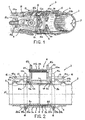
- la figure 1 est une vue en perspective d'un dispositif d'accouplement selon l'invention ;
- la figure 2 est une vue en coupe longitudinale du dispositif d'accouplement ;
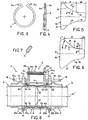
- la figure 3 est une vue de face d'un des deux anneaux à ressort utilisé dans le dispositif d'accouplement des figures 1 et 2 ;
- la figure 4 est une vue de côté de l'anneau de la figure 3 ;
- la figure 5 montre, à plus grande échelle, la forme de la lumière réalisée dans chacune des deux cames utilisées dans le dispositif d'accouplement selon l'invention ;
- la figure 6 montre une autre forme possible pour la lumière des cames ;
- la figure 7 est une vue partielle en coupe suivant la ligne A-A de la figure 5 ou 6 ;
- la figure 8 est une vue semblable à la figure 2 montrant une variante de réalisation.
- Figure 1 is a perspective view of a coupling device according to the invention;
- Figure 2 is a longitudinal sectional view of the coupling device;
- Figure 3 is a front view of one of the two spring rings used in the coupling device of Figures 1 and 2;
- Figure 4 is a side view of the ring of Figure 3;
- Figure 5 shows, on a larger scale, the shape of the light made in each of the two cams used in the coupling device according to the invention;
- Figure 6 shows another possible form for cam light;
- Figure 7 is a partial sectional view along line AA of Figure 5 or 6;
- Figure 8 is a view similar to Figure 2 showing an alternative embodiment.
En se reportant aux figures 1 et 2 on peut voir deux tubes 1 et 2
accouplés l'un à l'autre de manière étanche par un dispositif
d'accouplement 3 selon l'invention. Le dispositif d'accouplement 3 se
compose essentiellement d'un manchon 4 fendu longitudinalement, d'une
garniture d'étanchéité 5 et de moyens de serrage 6. La fente du manchon
4 est visible en 7 dans la figure 1, mais n'a pas été représentée dans la
figure 2. Le dispositif d'accouplement 3 est représenté à l'état serré dans
la figure 1 et dans la moitié inférieure de la figure 2, tandis qu'il est
représenté à l'état desserré dans la moitié supérieure de la figure 2.Referring to Figures 1 and 2 we can see two
Comme cela est mieux visible dans la figure 2, la garniture d'étanchéité 5
est constituée par une pièce métallique de révolution 8 à paroi mince, qui
entoure les parties d'extrémités 1a et 2a des deux tubes 1 et 2. A chacune
de ses extrémités, la pièce de révolution 8 comporte un collet 8a ou 8b
rabattu vers l'extérieur. Les deux collets 8a et 8b sont respectivement
engagés dans des gorges 4a et 4b formées dans la surface périphérique
intérieure du manchon fendu 4.As best seen in Figure 2, the
De préférence, les collets 8a et 8b ont une dimension radiale
sensiblement égale à cinq fois l'épaisseur de la paroi de la pièce de
révolution 8 et les gorges 4a et 4b ont une profondeur sensiblement égale
au 3/5 de la dimension radiale des collets 8a et 8b et une largeur
sensiblement égale à trois fois l'épaisseur de la paroi de la pièce de
révolution 8. Par exemple, la pièce de révolution 8 peut être en acier
doux revêtu d'aluminium ou en axier inoxydable et elle a une épaisseur
de paroi d'environ 0,5mm. Dans ces conditions, les collets 8a et 8b
peuvent avoir une dimension radiale d'environ 2,5mm et les gorges 4a et
4b peuvent avoir une profondeur d'environ 1,5mm et une largeur
d'environ 1,5mm.Preferably, the
Entre les deux gorges 4a et 4b, le manchon fendu 4 présente, dans sa
surface périphérique intérieure, une gorge ou renfoncement 4c ayant une
largeur nettement plus grande que celle des deux gorges 4a et 4b. Il est
ainsi formé deux renflements intérieurs 4d et 4e respectivement entre les
gorges 4a et 4c et entre les gorges 4c et 4b. De préférence, les deux
renflements intérieurs 4d et 4e ont une surface périphérique intérieure
qui est décalée radialement vers l'extérieur par rapport à la surface
périphérique intérieure du manchon 4 dans ses régions situées au- delà
des deux gorges 4a et 4b vers les extrémités dudit manchon. Par
exemple, ledit décalage radial peut être d'environ 0,6mm.Between the two
Le manchon fendu 4 peut être par exemple réalisé à partir d'une bande 9
en acier doux revêtu d'aluminium ou en axier inoxydable, ayant une
épaisseur de 1,2mm. Dans ces conditions, les gorges 4a, 4b et 4c peuvent
être avantageusement réalisées de manière simple par une opération de
roulage ou de laminage de ladite bande d'acier 9.The
Dans le mode de réalisation du dispositif d'accouplement représenté sur
les figures 1 et 2, les moyens de serrage 6 se composent essentiellement
de deux anneaux ouverts à ressort 11 et de deux cames 12
respectivement associés aux anneaux à ressort 11. Chaque anneau à
ressort 11 entoure le manchon fendu 4 dans une région de celui- ci située
à proximité de la gorge 4a ou 4b comme montré dans la figure 2. Chaque
anneau à ressort 11 comporte deux extrémités 11a en forme de crochet
comme montré dans la figure 3. Chaque anneau à ressort 11 est de
préférence réalisé à partir d'un fil d'acier demi- dur, revêtu d'aluminium,
ayant par exemple un diamètre de 3mm. De préférence, chaque anneau à
ressort 11 est conformé de manière à présenter un profil ondulé par
rapport à un plan moyen PM dudit anneau à ressort, comme montré dans
la figure 4. L'amplitude crête à crête e des ondulations du profil ondulé
peut être par exemple égale à environ 2 fois le diamètre du fil d'acier
formant l'anneau à ressort 11. Ce profil ondulé est destiné à permettre un
léger allongement élastique de l'anneau à ressort 11 dans le sens
circonférentiel lorsqu'il est serré autour du manchon fendu 4. In the embodiment of the coupling device shown in
FIGS. 1 and 2, the clamping means 6 consist essentially of
two open spring rings 11 and two
Chaque came 12 comporte une lumière 13 dans laquelle sont engagées
les extrémités en forme de crochet 11a de l'anneau à ressort 11 associé à
la came. Comme montré dans la figure 5, la lumière 13 a une partie large
I se raccordant par une partie II de largeur décroissante à une partie
étroite III. Ainsi, un déplacement relatif de la came 12 par rapport aux
extrémités en forme de crochet 11a de l'anneau à ressort 11 depuis la
partie large I jusqu'à la partie étroite III de la lumière 13 provoque un
rapprochement mutuel des deux extrémités 11a de l'anneau à ressort 11
et, par suite, un resserrement de ce dernier autour du manchon fendu 4.
La lumière 13 a une forme symétrique par rapport à son axe
longitudinal X.Each
Dans la forme de réalisation de la lumière représentée sur la figure 5, les
deux bords longitudinaux de la partie II de la lumière 13 comportent
successivement, de la partie I vers la partie III de la lumière 13, une
première partie courbe 14, dont la convexité est orientée vers l'axe X,
suivie d'une seconde partie 15 rectiligne. Une telle forme de la lumière
13 permet, lorsque la came 12 est déplacée de droite à gauche dans la
direction de l'axe X par rapport aux extrémités 11a de l'anneau 11
supposé fixe, d'obtenir tout d'abord un rapprochement relativement
rapide des deux extrémités 11a de l'anneau 11 au début du déplacement
de la came lorsque l'effort de serrage à exercer est relativement faible
(rattrapage d'un éventuel jeu radial entre l'anneau 11 et le manchon 4),
puis d'obtenir un rapprochement plus lent des extrémités 11a de l'anneau
11 quand les efforts radiaux de serrage à exercer sur le manchon 4 pour
le comprimer radialement deviennent plus importants. Dans les bords
longitudinaux de la partie III de la lumière 13 sont de préférence formés
deux évidements 16 peu profonds, qui se font mutuellement face et qui
ont un profil en arc de cercle dont le rayon correspond au rayon du fil
d'acier formant l'anneau 11. Ainsi, en fin de serrage, le fil d'acier de
l'anneau 11 vient s'encliqueter dans les deux évidements 16 de la partie
III de la lumière 13.In the embodiment of the light shown in FIG.
two longitudinal edges of the portion II of the light 13 comprise
successively, from part I to part III of
Dans la variante de réalisation représentée sur la figure 6, la partie II de
la lumière 13 a une longueur plus grande que la partie correspondante de
la lumière 13 de la figure 5, et chacun de ses deux bords longitudinaux
comporte une succession de segments, par exemple trois segments 17, 18
et 19 qui font respectivement des angles 1, 2 et 3, de valeurs
décroissantes, avec l'axe longitudinal X de la lumière 13. A titre
d'exemple, 1 peut être égal à environ 41°, 2 à environ 22° et 3 à
environ 11°.In the variant embodiment shown in FIG. 6, the portion II of the
Dans les deux modes de réalisation des figures 5 et 6, les bords
longitudinaux de la lumière 13 ont de préférence un contour arrondi,
comme montré en 21 dans la figure 7, afin de ne pas blesser le fil d'acier
constituant l'anneau 11 lors du déplacement de la came 12 par rapport à
l'anneau 11.In both embodiments of Figures 5 and 6, the edges
longitudinal axes of the light 13 preferably have a rounded contour,
as shown in 21 in Figure 7, so as not to hurt the steel wire
constituting the
En se reportant à nouveau aux figures 1 et 2, on peut voir que chaque
came 12 a une forme générale en L, avec une première branche 12a qui
s'étend parallèlement à l'axe longitudinal X' du manchon 4, et une
seconde branche 12b qui s'étend perpendiculairement audit axe X'. La
lumière 13 de chaque came 12 est formée dans la première branche 12a.Referring back to Figures 1 and 2, we can see that each
Dans ce cas, les moyens de serrage 6 comprennent en outre un dispositif
de serrage à vis apte à coopérer avec les branches 12a des cames 12 pour
provoquer simultanément un déplacement relatif des deux cames 12 par
rapport aux anneaux 11. Dans ce cas, les deux branches 12a des cames
12 s'étendent dans des directions opposées et la partie étroite III de la
lumière 13 de chaque came se trouve près de l'extrémité libre de la
branche 12a de la came 12 correspondante. Le dispositif de serrage à vis
peut être constitué par une unique vis 22 dont la tête 22a prend appui sur
la branche 12b d'une des deux cames 12 et dont la tige filetée 22b passe
librement à travers un trou lisse 23 dans la branche 12b de ladite came
12 et est vissée dans un trou taraudé 24 dans la branche 12b de l'autre
came 12. Dans une variante de réalisation, le trou 24 peut être un trou
lisse et un écrou (non-montré) peut être vissé sur l'extrémité libre de la
tige filetée 22b de la vis 22, de façon à déplacer l'une vers l'autre les
branches 12b des deux cames 12 lorsque l'ensemble vis-écrou est serré.In this case, the clamping means 6 further comprise a device
screw clamping adapted to cooperate with the
De préférence, le manchon 4 comporte des moyens de positionnement
pour définir la position axiale des anneaux 11 dans les régions du
manchon 4 situé à proximité des deux gorges 4a et 4b. Dans le cas où les
gorges 4a, 4b et 4c du manchon 4 sont formées par une opération de
roulage ou de laminage d'une bande d'acier 9, lesdits moyens de
positionnement peuvent être avantageusement formés par déformation
localisée, vers l'extérieur, de la paroi du manchon 4 lors de ladite
opération de roulage ou de laminage. Etant donné qu'à chacune des deux
gorges 4a et 4b correspond déjà un renflement extérieur 25a ou 25b,
respectivement, sur la surface périphérique extérieure du manchon 4, il
suffit de former deux renflements 26a et 26b sur la surface périphérique
extérieure du manchon 4, respectivement à proximité des deux
renflements 25a et 25b, de manière à définir deux gorges 27a et 27b
aptes à recevoir et positionner les deux anneaux 11, respectivement,
comme montré dans la figure 2.Preferably, the
A titre de variante, les renflements 26a et 26b peuvent être remplacés par
plusieurs protubérances obtenues par découpage et emboutissage de la
bande d'acier 9 constituant le manchon 4, comme montré en 28 dans la
figure 1, ou encore par des languettes (non-montrées) obtenues par
découpage de la bande d'acier 9 et repliées à angle droit de façon à
s'étendre radialement par rapport au manchon 4.Alternatively, the
De préférence, le manchon 4 comporte deux encoche s 29a et 29b dans
ses extrémités, comme montré dans les figures 1 et 2. Les encoches 29a
et 29b sont destinées à recevoir des protubérances 31 a et 31b qui font
saillie respectivement sur la périphérie des parties d'extrémités 1a et 2a
des deux tubes 1 et 2. Les encoches 29a et 29b et les protubérances 31a
et 31b définissent à la fois des moyens de positionnement angulaire et
des moyens de positionnement axial du manchon 4 par rapport aux tubes
1 et 2. Ainsi, lorsque, en service, les parties d'extrémités 1a et 2a des
deux tubes 1 et 2 sont engagées dans le manchon 4 et dans la pièce de
révolution 8 constituant la garniture d'étanchéité 5 et que les deux
protubérances 31a et 31b sont engagées dans les encoches 29a et 29b du
manchon 4, on est assuré que les extrémités mutuellement en vis à vis
des deux tubes 1 et 2 se trouveront exactement dans la région médiane
du manchon 4 et de la pièce de révolution 8, entre les deux gorges
4a et 4b.Preferably, the
Les deux protubérances 31a et 31b peuvent être par exemple formées par
emboutissage de la paroi des tubes 1 et 2 comme montré dans la figure 2.The two
A titre de variante (non-montrée), les deux protubérances peuvent être
constituées par des pions soudés respectivement sur les deux tubes 1 et 2.As a variant (not shown), the two protuberances can be
constituted by pins respectively welded to the two
Selon une autre variante montrée dans la figure 8, le manchon 4 ne
comporte pas d'encoche à ses extrémités et les tubes 1 et 2 sont
dépourvus de protubérance. Dans ce cas, le positionnement axial du
manchon 4 et de la pièce de révolution 8 par rapport aux deux tubes 1 et
2 est obtenu de la manière suivante. Dans sa région médiane, la pièce de
révolution 8 comporte au moins une protubérance 32 qui fait radialement
saillie vers l'intérieur sur la surface périphérique intérieure de la pièce de
révolution 8 et qui définit une butée axiale pour les deux tubes 1 et 2. La
protubérance 32 peut être unique et s'étendre sur la totalité de la
circonférence de la pièce de révolution 8. A titre de variante, il peut être
prévu plusieurs protubérances 32 formées par emboutissage dans la paroi
mince de la pièce de révolution 8 en des points régulièrement espacés le
long de la circonférence de celle-ci, par exemple deux protubérances
diamétralement opposées ou trois protubérances espacées de 120°.According to another variant shown in FIG. 8, the
L'accouplement étanche des tubes 1 et 2 à l'aide du dispositif
d'accouplement 3 décrit ci-dessus s'effectue de la manière suivante.
Alors que le dispositif d'accouplement 3 est dans l'état desserré montré
dans la moitié supérieure de la figure 2, dans lequel les deux cames 12
sont écartées l'une de l'autre et les extrémités 11a des deux anneaux à
ressort 11 se trouvent dans la partie large I de la lumière 13 des cames
12, on engage tout d'abord les parties d'extrémités 1a et 2a des tubes 1 et
2 respectivement dans les extrémités du manchon 4, jusqu'à ce que les
protubérances 31a et 31b viennent buter contre le fond des encoches 29a
et 29b (figure 2), ou jusqu'à ce que les extrémités des tubes 1 et 2
viennent en butée contre la ou les protubérances 32 de la pièce de
révolution 8. Ensuite, la vis 22 est tournée au moyen d'une clef
appropriée dans le sens du vissage, ce qui a pour effet de rapprocher les
deux cames 12 l'une de l'autre, donc de rapprocher les deux extrémités
11a de chacun des deux anneaux 11 à ressort 11 l'une de l'autre. Il en
résulte que les deux anneaux 11 compriment radialement le manchon
fendu 4 dont la fente 7 devient de plus en plus étroite. Au cours du
serrage du manchon 4 par les moyens de serrage 6, le fond des gorges 4a
et 4b du manchon 4 agit sur la périphérie des collets 8a, 8b,
respectivement, sur toute leur circonférence, et provoque un rétreint des
zones d'extrémités 8c et 8d de la pièce de révolution 8, amenant ainsi
lesdites zones d'extrémités 8c et 8d en contact étanche avec la surface
périphérique extérieure des parties d'extrémités 1a et 2a des tubes 1 et 2,
sur toute leur circonférence. A la fin du serrage, le dispositif
d'accouplement est dans l'état représenté dans la moitié inférieure de la
figure 2 (ou dans la moitié inférieure de la figure 8).The sealed coupling of
Les expériences réalisées par le demandeur ont montré que, avec le
mode de réalisation du dispositif d'accouplement décrit plus haut, il est
possible d'obtenir un rétreint relativement important des zones
d'extrémités 8c et 8d de la pièce de révolution 8. La réduction de
diamètre de la pièce de révolution 8 dans les zones d'extrémités 8c et 8d
peut atteindre environ 3mm. Le rétreint de ces zones d'extrémités 8c et
8d est facilité par le fait que la partie médiane de la pièce de révolution 8
peut s'expanser radialement vers l'extérieur dans la gorge ou
renfoncement 4c du manchon 4. En outre, les expériences réalisées par le
demandeur ont montré que la portée d'appui de chacune des deux zones
d'extrémités 8c et 8d sur le tube 1 ou 2 a une largeur d'environ 3mm et
est parfaitement lisse, assurant ainsi une bonne étanchéité entre les deux
tubes 1 et 2 et la pièce de révolution 8.The experiments carried out by the applicant showed that, with the
embodiment of the coupling device described above, it is
possible to achieve a relatively large shrinkage of the areas
ends 8c and 8d of the piece of
La vis 22 peut être supprimée et
que chacune des deux cames 12 peut être constituée par un levier
pivotant apte à agir sur les deux extrémités 11a de l'anneau à ressort 11
correspondant pour rapprocher les deux extrémités 11a l'une de l'autre
lorsqu'on fait pivoter le levier d'un angle d'environ 180° autour d'un axe
orthogonal à l'axe X du manchon fendu 4. Par exemp le, chaque levier
peut être constitué par une plaque d'acier, de forme allongée, dans l'une
des extrémités de laquelle est découpée une languette qui a une forme
semblable à celle de la lumière 13 de la figure 5 ou de la figure 6 et qui
reste attachée à ladite plaque par l'extrémité de la partie étroite de la
languette. A son extrémité attachée à la plaque, la languette est pliée
autour d'une ligne de pliage s'étendant perpendiculairement à l'axe
longitudinal de la plaque, de façon à s'étendre obliquement v ers
l'extérieur par rapport à la plaque et de façon à dégager une lumière
semblable à la lumière 13 de la figure 5 ou 6. La partie de la plaque
formant les deux côtés longitudinaux de la lumière est recourbée vers
l'extrémité libre de la languette de manière à former avec cette dernière
un oeillet pour le montage pivotant du levier sur les extrémités 11a de
l'anneau à ressort 11 correspondant.The
Claims (15)
- Device for the leakproof coupling of two smooth, rigid tubes (1, 2) of the same diameter lying along the same axis (X') opposite one another, which comprises a sealing element (5) that surround an end portion (1a, 2a) of each of two tubes positioned opposite one another, a sleeve (4) split longitudinally that surround the said sealing element (5), and tightening means (6) for tightening the said sleeve (4) radially around the sealing element (5) and for pressing the said sealing element (5) radially against the periphery of the end portions of the two tubes (1, 2), characterised in that the sealing element (5) consists of a thin-walled, rotationally symmetric metallic fitting (8) having the general shape of a cylinder with two collars (8a, 8b) bent outwards at it ends, and the split sleeve (4) is shaped so that its inner peripheral surface has two grooves (4a, 4b) that can receive, respectively, the two collars (8a, 8b) of the said rotationally symmetric fitting (8), the depth of the grooves being smaller than the radial height of the two collars so that the bottom of the grooves (4a, 4b) can act upon the periphery of the collars, in each case all round their circumference, to constrict the end zones (8c, 8d) of the said rotationally symmetric fitting (8) and bring the said end zones into leakproof contact with the outer peripheral surface of the end portions (1a, 2a) of the two tubes all around their circumference during the tightening of the split sleeve (4) by the tightening means (6) around the said rotationally symmetric fitting (8).
- Device according to Claim 1, characterised in that the radial height of the said collars (8a, 8b) is essentially five times the wall thickness of the said rotationally symmetric fitting (8) and the depth of the said grooves is essentially equal to 3/5 of the radial height of the collars and their width is essentially equal to three times the wall thickness of the said rotationally symmetric fitting.
- Device according to Claims 1 or 2, characterised in that the said rotationally symmetric fitting (8) is made of mild steel clad with aluminium or stainless steel.
- Device according to and of Claims 1 to 3, characterised in that the wall thickness of the said rotationally symmetric fitting (8) is approximately 0.5 mm, the radial height of the collars (8a, 8b) is approximately 2.5 mm and the depth of the grooves is approximately 1.5 mm.
- Device according to any of Claims 1 to 4, characterised in that the split sleeve (4) is shaped so that its inner peripheral surface has, between the two grooves (4a, 4b), an additional groove (4c) wider than the other two grooves, with an inner bulge (4d, 4e) between each of the tow grooves and the said additional groove, the said inner bulge having a peripheral surface which is offset radially outwards relative to the inner peripheral surface of the sleeve (4) in its areas beyond the two grooves (4a, 4b) towards the ends of the said sleeve.
- Device according to any of Claims 1 to 5, characterised in that the grooves (4a, 4b, 4c) of the split sleeve are formed by a rolling or laminating operation on a strip (9) of mild steel clad with aluminium or stainless steel.
- Device according to any of Claims 1 to 6, characterised in that the tightening means (6) comprise two open spring-rings (11), which surround the split sleeve (4) in areas thereof located respectively close to the two grooves (4a, 4b), and two cams (12) respectively associated with the two spring-rings (11) and which can act upon hook-shaped ends (11 a) of the two spring-rings to tighten the said spring-rings around the said split sleeve and compress the latter radially.
- Device according to Claim 7, characterised in that each spring-ring (11) has a profile that undulates relative to a mean plane (PM) of the spring-ring.
- Device according to Claims 7 or 8, characterised in that each cam (12) comprises an opening (13) in which the hook-shaped ends (11a) of the spring-ring (11) associated with the cam are engaged, the said opening having a wide part (I) joined by a section (II) of diminishing width to a narrow part (III), such that a movement of the cam (12) relative to the hook-shaped ends (11a) of the associated spring-ring from the wide part (I) to the narrow part (III) of the opening (13) causes the spring-ring (11) to tighten.
- Device according to Claim 9, characterised in that each cam (12) has the general shape of an L, a first branch (12a) of which extends parallel to the longitudinal axis (X') of the split sleeve (4) while a second branch (12b) extends perpendicularly to the said longitudinal axis, the said opening (13) being formed in the first branch (12a), and the tightening means (6) also comprise a screw tightening element (22) which co-operates with the second branches (12b) of the two cams (12) to produce a simultaneous relative movement of the two cams.
- Device according to Claim 10, characterised in that the first branches (12a) of the two cams (12) extend in opposite directions, the narrow part (III) of the opening (13) in each cam (12) is near the free end of the first branch (12a) of the corresponding cam, and the screw tightening element (22) consists of a bolt (22) whose head (22a) is in contact with the second branch (12b) of a first of the two cams (12) while its threaded shank (22b) passes freely though a smooth hole (23) in the second branch (12b) and is screwed into a threaded hole (24) in the second branch (12b) of the second cam.
- Device according to Claims 10 or 11, characterised in that the split sleeve (4) comprises positioning means (25a - 27a; 25b - 27b) for defining the axial position of the spring-rings (11) in the said areas of the split sleeve (4) located near the two grooves (4a, 4b).
- Device according to Claims 6 and 12, characterised in that the said positioning means (25a - 27a; 25b - 27b) are formed by the local, outward deformation of the wall of the split sleeve (4) during the said rolling or lamination operation of the said mild steel strip (9).
- Device according to any of Claims 1 to 13, characterised in that two notches (29a, 29b) are formed respectively in the ends of the split sleeve (4) and can receive protuberances (31a, 31b) which project respectively on the periphery of the end portions (1a, 2a) of the two tubes (1, 2) to be coupled, so as to define both angular and axial positioning means of the split sleeve (4) relative to the two tubes (1, 2), such that in service, the mutually opposed ends of the two tubes are in the median area of the split sleeve and between the two grooves (4a, 4b) of the latter.
- Device according to any of Claims 1 to 13, characterised in that in its median area the said rotationally symmetric fitting has at least one protuberance (32) which projects radially inwards on the inner peripheral surface of the rotationally symmetric fitting and which defines an axial abutment for the two tubes (1, 2) to be coupled.
Applications Claiming Priority (3)
| Application Number | Priority Date | Filing Date | Title |
|---|---|---|---|
| FR0116664 | 2001-12-21 | ||
| FR0116664A FR2834040B1 (en) | 2001-12-21 | 2001-12-21 | WATERPROOF COUPLING DEVICE FOR TWO RIGID TUBES OF THE SAME OUTER DIAMETER |
| PCT/FR2002/004450 WO2003054431A1 (en) | 2001-12-21 | 2002-12-19 | Device for sealed coupling of two rigid tubes of same external diameter |
Publications (2)
| Publication Number | Publication Date |
|---|---|
| EP1456573A1 EP1456573A1 (en) | 2004-09-15 |
| EP1456573B1 true EP1456573B1 (en) | 2005-08-17 |
Family
ID=8870841
Family Applications (1)
| Application Number | Title | Priority Date | Filing Date |
|---|---|---|---|
| EP02799104A Expired - Lifetime EP1456573B1 (en) | 2001-12-21 | 2002-12-19 | Device for sealed coupling of two rigid tubes of same external diameter |
Country Status (7)
| Country | Link |
|---|---|
| EP (1) | EP1456573B1 (en) |
| AT (1) | ATE302376T1 (en) |
| AU (1) | AU2002364330A1 (en) |
| DE (1) | DE60205661T2 (en) |
| ES (1) | ES2247418T3 (en) |
| FR (1) | FR2834040B1 (en) |
| WO (1) | WO2003054431A1 (en) |
Families Citing this family (3)
| Publication number | Priority date | Publication date | Assignee | Title |
|---|---|---|---|---|
| US5841169A (en) * | 1996-06-27 | 1998-11-24 | Harris Corporation | Integrated circuit containing devices dielectrically isolated and junction isolated from a substrate |
| DE102022206524B4 (en) | 2022-06-28 | 2025-08-21 | Zf Friedrichshafen Ag | Lamellar switching element with a wave spring, bearing arrangement and drive device |
| CN115255995B (en) * | 2022-09-06 | 2023-08-29 | 富泰克精密注塑(苏州)有限公司 | Abrasion-proof clamp capable of uniformly clamping thin-wall tubular part |
Family Cites Families (7)
| Publication number | Priority date | Publication date | Assignee | Title |
|---|---|---|---|---|
| GB570913A (en) * | 1943-12-20 | 1945-07-27 | George Taylor | Improvements in the joining of pipes |
| US3479066A (en) | 1967-07-03 | 1969-11-18 | Morris Gittleman | Pipe coupling |
| FR1537581A (en) * | 1967-09-25 | 1968-08-23 | Mechanical assembly for smooth pipes resistant to dislocation | |
| US3724878A (en) * | 1971-03-24 | 1973-04-03 | J Ford | Flexible connector |
| DE3843738A1 (en) | 1987-12-29 | 1989-07-20 | Mannesmann Ag | Clamp for connecting rigid metal pipes |
| FR2662486B1 (en) | 1990-05-23 | 1992-09-11 | Caillau Ets | WATERPROOF COUPLING DEVICE FOR TWO SMOOTH TUBES, END TO END. |
| DE19901663C2 (en) * | 1999-01-18 | 2001-02-22 | Rasmussen Gmbh | Pipe coupling |
-
2001
- 2001-12-21 FR FR0116664A patent/FR2834040B1/en not_active Expired - Fee Related
-
2002
- 2002-12-19 DE DE60205661T patent/DE60205661T2/en not_active Expired - Fee Related
- 2002-12-19 AU AU2002364330A patent/AU2002364330A1/en not_active Abandoned
- 2002-12-19 AT AT02799104T patent/ATE302376T1/en not_active IP Right Cessation
- 2002-12-19 EP EP02799104A patent/EP1456573B1/en not_active Expired - Lifetime
- 2002-12-19 ES ES02799104T patent/ES2247418T3/en not_active Expired - Lifetime
- 2002-12-19 WO PCT/FR2002/004450 patent/WO2003054431A1/en not_active Ceased
Also Published As
| Publication number | Publication date |
|---|---|
| FR2834040A1 (en) | 2003-06-27 |
| DE60205661D1 (en) | 2005-09-22 |
| ATE302376T1 (en) | 2005-09-15 |
| EP1456573A1 (en) | 2004-09-15 |
| WO2003054431A1 (en) | 2003-07-03 |
| AU2002364330A1 (en) | 2003-07-09 |
| DE60205661T2 (en) | 2006-06-08 |
| FR2834040B1 (en) | 2004-04-02 |
| ES2247418T3 (en) | 2006-03-01 |
Similar Documents
| Publication | Publication Date | Title |
|---|---|---|
| EP0511891B1 (en) | Connector for the quick coupling of a tube | |
| EP3217059B1 (en) | Tightening system comprising a collar and isolated pre-mounting clips | |
| BE898358A (en) | Clamping structure without ear. | |
| FR2833065A1 (en) | CLAMPING SYSTEM FOR THE SEALED CONNECTION OF TWO TUBES HAVING SUPPORT SURFACES | |
| FR2915537A1 (en) | CLAMPING DEVICE | |
| EP0458700B1 (en) | Sealed butt end joining of two smooth pipes | |
| FR2882420A1 (en) | STRENGTH FOR MAINTAINING CLAMPING COLLAR | |
| EP1697672B1 (en) | Method of making a clamping collar | |
| FR2813374A1 (en) | CONNECTION OF A TUBULAR PIPING ELEMENT WITH A DUCT | |
| FR2666635A1 (en) | TUBULAR COUPLING. | |
| FR2697612A1 (en) | Hose clamp, especially for flexible pipes. | |
| EP0403379A1 (en) | Connecting ring for exhaust pipes | |
| EP1456573B1 (en) | Device for sealed coupling of two rigid tubes of same external diameter | |
| FR2842276A1 (en) | TIGHTENING COLLAR | |
| EP1413815A1 (en) | Coupling for two flared-end pipes | |
| FR2772875A1 (en) | Connector for flexible pipe and wall, especially for vehicle heat exchanger | |
| EP0581678B1 (en) | Hose with radial clamping device for connecting to a pipe end; connector with said hose | |
| FR2889286A1 (en) | STRUCTURE FOR MAINTAINING A FLEXIBLE PIPE CLAMP | |
| EP3734130B1 (en) | Tightening device comprising a sealing gasket and assembly comprising such a device | |
| FR2594205A1 (en) | End connector for a flexible pipe | |
| EP2154410B1 (en) | Clamping assembly and tubular connection | |
| FR2769068A1 (en) | TIGHTENING COLLAR DEVICE FOR RIGIDALLY TAPING A FLEXIBLE PIPE ON A TUBULAR PART | |
| FR2527708A1 (en) | Flexible cable tie with mounting eye near head - uses flexible locking tongue and has enlarged circular eye to mount tie onto support | |
| WO2025181437A1 (en) | Clamping collar with clamping lug and clamping rod | |
| FR2717555A1 (en) | Clamping collar for fixing flexible tube on connector |
Legal Events
| Date | Code | Title | Description |
|---|---|---|---|
| PUAI | Public reference made under article 153(3) epc to a published international application that has entered the european phase |
Free format text: ORIGINAL CODE: 0009012 |
|
| 17P | Request for examination filed |
Effective date: 20040616 |
|
| AK | Designated contracting states |
Kind code of ref document: A1 Designated state(s): AT BE BG CH CY CZ DE DK EE ES FI FR GB GR IE IT LI LU MC NL PT SE SI SK TR |
|
| AX | Request for extension of the european patent |
Extension state: AL LT LV MK RO |
|
| GRAP | Despatch of communication of intention to grant a patent |
Free format text: ORIGINAL CODE: EPIDOSNIGR1 |
|
| GRAS | Grant fee paid |
Free format text: ORIGINAL CODE: EPIDOSNIGR3 |
|
| GRAA | (expected) grant |
Free format text: ORIGINAL CODE: 0009210 |
|
| AK | Designated contracting states |
Kind code of ref document: B1 Designated state(s): AT BE BG CH CY CZ DE DK EE ES FI FR GB GR IE IT LI LU MC NL PT SE SI SK TR |
|
| PG25 | Lapsed in a contracting state [announced via postgrant information from national office to epo] |
Ref country code: EE Free format text: LAPSE BECAUSE OF FAILURE TO SUBMIT A TRANSLATION OF THE DESCRIPTION OR TO PAY THE FEE WITHIN THE PRESCRIBED TIME-LIMIT Effective date: 20050817 Ref country code: FI Free format text: LAPSE BECAUSE OF FAILURE TO SUBMIT A TRANSLATION OF THE DESCRIPTION OR TO PAY THE FEE WITHIN THE PRESCRIBED TIME-LIMIT Effective date: 20050817 Ref country code: SI Free format text: LAPSE BECAUSE OF FAILURE TO SUBMIT A TRANSLATION OF THE DESCRIPTION OR TO PAY THE FEE WITHIN THE PRESCRIBED TIME-LIMIT Effective date: 20050817 Ref country code: NL Free format text: LAPSE BECAUSE OF FAILURE TO SUBMIT A TRANSLATION OF THE DESCRIPTION OR TO PAY THE FEE WITHIN THE PRESCRIBED TIME-LIMIT Effective date: 20050817 Ref country code: SK Free format text: LAPSE BECAUSE OF FAILURE TO SUBMIT A TRANSLATION OF THE DESCRIPTION OR TO PAY THE FEE WITHIN THE PRESCRIBED TIME-LIMIT Effective date: 20050817 Ref country code: AT Free format text: LAPSE BECAUSE OF FAILURE TO SUBMIT A TRANSLATION OF THE DESCRIPTION OR TO PAY THE FEE WITHIN THE PRESCRIBED TIME-LIMIT Effective date: 20050817 Ref country code: TR Free format text: LAPSE BECAUSE OF FAILURE TO SUBMIT A TRANSLATION OF THE DESCRIPTION OR TO PAY THE FEE WITHIN THE PRESCRIBED TIME-LIMIT Effective date: 20050817 Ref country code: IE Free format text: LAPSE BECAUSE OF FAILURE TO SUBMIT A TRANSLATION OF THE DESCRIPTION OR TO PAY THE FEE WITHIN THE PRESCRIBED TIME-LIMIT Effective date: 20050817 Ref country code: CZ Free format text: LAPSE BECAUSE OF FAILURE TO SUBMIT A TRANSLATION OF THE DESCRIPTION OR TO PAY THE FEE WITHIN THE PRESCRIBED TIME-LIMIT Effective date: 20050817 |
|
| REG | Reference to a national code |
Ref country code: GB Ref legal event code: FG4D Free format text: NOT ENGLISH |
|
| REG | Reference to a national code |
Ref country code: CH Ref legal event code: EP |
|
| REG | Reference to a national code |
Ref country code: IE Ref legal event code: FG4D Free format text: LANGUAGE OF EP DOCUMENT: FRENCH |
|
| REF | Corresponds to: |
Ref document number: 60205661 Country of ref document: DE Date of ref document: 20050922 Kind code of ref document: P |
|
| GBT | Gb: translation of ep patent filed (gb section 77(6)(a)/1977) |
Effective date: 20050927 |
|
| PG25 | Lapsed in a contracting state [announced via postgrant information from national office to epo] |
Ref country code: SE Free format text: LAPSE BECAUSE OF FAILURE TO SUBMIT A TRANSLATION OF THE DESCRIPTION OR TO PAY THE FEE WITHIN THE PRESCRIBED TIME-LIMIT Effective date: 20051117 Ref country code: BG Free format text: LAPSE BECAUSE OF FAILURE TO SUBMIT A TRANSLATION OF THE DESCRIPTION OR TO PAY THE FEE WITHIN THE PRESCRIBED TIME-LIMIT Effective date: 20051117 Ref country code: GR Free format text: LAPSE BECAUSE OF FAILURE TO SUBMIT A TRANSLATION OF THE DESCRIPTION OR TO PAY THE FEE WITHIN THE PRESCRIBED TIME-LIMIT Effective date: 20051117 Ref country code: DK Free format text: LAPSE BECAUSE OF FAILURE TO SUBMIT A TRANSLATION OF THE DESCRIPTION OR TO PAY THE FEE WITHIN THE PRESCRIBED TIME-LIMIT Effective date: 20051117 |
|
| PG25 | Lapsed in a contracting state [announced via postgrant information from national office to epo] |
Ref country code: CY Free format text: LAPSE BECAUSE OF FAILURE TO SUBMIT A TRANSLATION OF THE DESCRIPTION OR TO PAY THE FEE WITHIN THE PRESCRIBED TIME-LIMIT Effective date: 20051219 |
|
| PG25 | Lapsed in a contracting state [announced via postgrant information from national office to epo] |
Ref country code: MC Free format text: LAPSE BECAUSE OF NON-PAYMENT OF DUE FEES Effective date: 20051231 Ref country code: BE Free format text: LAPSE BECAUSE OF NON-PAYMENT OF DUE FEES Effective date: 20051231 Ref country code: LU Free format text: LAPSE BECAUSE OF NON-PAYMENT OF DUE FEES Effective date: 20051231 |
|
| PG25 | Lapsed in a contracting state [announced via postgrant information from national office to epo] |
Ref country code: PT Free format text: LAPSE BECAUSE OF FAILURE TO SUBMIT A TRANSLATION OF THE DESCRIPTION OR TO PAY THE FEE WITHIN THE PRESCRIBED TIME-LIMIT Effective date: 20060117 |
|
| NLV1 | Nl: lapsed or annulled due to failure to fulfill the requirements of art. 29p and 29m of the patents act | ||
| REG | Reference to a national code |
Ref country code: ES Ref legal event code: FG2A Ref document number: 2247418 Country of ref document: ES Kind code of ref document: T3 |
|
| REG | Reference to a national code |
Ref country code: IE Ref legal event code: FD4D |
|
| PLBE | No opposition filed within time limit |
Free format text: ORIGINAL CODE: 0009261 |
|
| STAA | Information on the status of an ep patent application or granted ep patent |
Free format text: STATUS: NO OPPOSITION FILED WITHIN TIME LIMIT |
|
| 26N | No opposition filed |
Effective date: 20060518 |
|
| PGFP | Annual fee paid to national office [announced via postgrant information from national office to epo] |
Ref country code: GB Payment date: 20061227 Year of fee payment: 5 |
|
| PGFP | Annual fee paid to national office [announced via postgrant information from national office to epo] |
Ref country code: DE Payment date: 20061229 Year of fee payment: 5 |
|
| PG25 | Lapsed in a contracting state [announced via postgrant information from national office to epo] |
Ref country code: CH Free format text: LAPSE BECAUSE OF NON-PAYMENT OF DUE FEES Effective date: 20061231 Ref country code: LI Free format text: LAPSE BECAUSE OF NON-PAYMENT OF DUE FEES Effective date: 20061231 |
|
| PGFP | Annual fee paid to national office [announced via postgrant information from national office to epo] |
Ref country code: IT Payment date: 20061231 Year of fee payment: 5 |
|
| PGFP | Annual fee paid to national office [announced via postgrant information from national office to epo] |
Ref country code: ES Payment date: 20070130 Year of fee payment: 5 |
|
| REG | Reference to a national code |
Ref country code: CH Ref legal event code: PL |
|
| BERE | Be: lapsed |
Owner name: LIMA Effective date: 20051231 |
|
| PGFP | Annual fee paid to national office [announced via postgrant information from national office to epo] |
Ref country code: FR Payment date: 20061229 Year of fee payment: 5 |
|
| GBPC | Gb: european patent ceased through non-payment of renewal fee |
Effective date: 20071219 |
|
| PG25 | Lapsed in a contracting state [announced via postgrant information from national office to epo] |
Ref country code: DE Free format text: LAPSE BECAUSE OF NON-PAYMENT OF DUE FEES Effective date: 20080701 |
|
| REG | Reference to a national code |
Ref country code: FR Ref legal event code: ST Effective date: 20081020 |
|
| PG25 | Lapsed in a contracting state [announced via postgrant information from national office to epo] |
Ref country code: GB Free format text: LAPSE BECAUSE OF NON-PAYMENT OF DUE FEES Effective date: 20071219 |
|
| REG | Reference to a national code |
Ref country code: ES Ref legal event code: FD2A Effective date: 20071220 |
|
| PG25 | Lapsed in a contracting state [announced via postgrant information from national office to epo] |
Ref country code: FR Free format text: LAPSE BECAUSE OF NON-PAYMENT OF DUE FEES Effective date: 20071231 Ref country code: ES Free format text: LAPSE BECAUSE OF NON-PAYMENT OF DUE FEES Effective date: 20071220 |
|
| PG25 | Lapsed in a contracting state [announced via postgrant information from national office to epo] |
Ref country code: IT Free format text: LAPSE BECAUSE OF NON-PAYMENT OF DUE FEES Effective date: 20071219 |