EP0807780B1 - Device for sealingly connecting two flat pipes - Google Patents
Device for sealingly connecting two flat pipes Download PDFInfo
- Publication number
- EP0807780B1 EP0807780B1 EP19970401049 EP97401049A EP0807780B1 EP 0807780 B1 EP0807780 B1 EP 0807780B1 EP 19970401049 EP19970401049 EP 19970401049 EP 97401049 A EP97401049 A EP 97401049A EP 0807780 B1 EP0807780 B1 EP 0807780B1
- Authority
- EP
- European Patent Office
- Prior art keywords
- ring
- tubes
- sleeve
- perforations
- free edges
- Prior art date
- Legal status (The legal status is an assumption and is not a legal conclusion. Google has not performed a legal analysis and makes no representation as to the accuracy of the status listed.)
- Expired - Lifetime
Links
- 230000008878 coupling Effects 0.000 claims abstract description 9
- 238000010168 coupling process Methods 0.000 claims abstract description 9
- 238000005859 coupling reaction Methods 0.000 claims abstract description 9
- 238000007789 sealing Methods 0.000 claims description 21
- 230000000694 effects Effects 0.000 claims description 3
- 239000007787 solid Substances 0.000 claims description 3
- 238000007688 edging Methods 0.000 claims 2
- 230000007423 decrease Effects 0.000 description 5
- 230000013011 mating Effects 0.000 description 3
- 239000011521 glass Substances 0.000 description 2
- 238000004519 manufacturing process Methods 0.000 description 2
- 230000000295 complement effect Effects 0.000 description 1
- 230000001627 detrimental effect Effects 0.000 description 1
- 238000000926 separation method Methods 0.000 description 1
Images
Classifications
-
- F—MECHANICAL ENGINEERING; LIGHTING; HEATING; WEAPONS; BLASTING
- F16—ENGINEERING ELEMENTS AND UNITS; GENERAL MEASURES FOR PRODUCING AND MAINTAINING EFFECTIVE FUNCTIONING OF MACHINES OR INSTALLATIONS; THERMAL INSULATION IN GENERAL
- F16L—PIPES; JOINTS OR FITTINGS FOR PIPES; SUPPORTS FOR PIPES, CABLES OR PROTECTIVE TUBING; MEANS FOR THERMAL INSULATION IN GENERAL
- F16L21/00—Joints with sleeve or socket
- F16L21/002—Sleeves or nipples for pipes of the same diameter; Reduction pieces
- F16L21/005—Sleeves or nipples for pipes of the same diameter; Reduction pieces made of elastic material, e.g. partly or completely surrounded by clamping devices
Definitions
- the present invention relates to a coupling device waterproof of two smooth tubes arranged end to end, having substantially the same diameter.
- Document FR-A-2 662 486 proposes a first solution to this problem by making the free edges of the ring beveled, so that these can be applied against each other and shift transversely one compared to when the diameter of the ring decreases. This solution is generally satisfactory, but it does not fully control the support of the two free edges one against the other nor of securing the ring to inside the sleeve.
- Document FR-A-2 689 204 shows a device in which the sealing ring has free edges shaped so as to fit in chicane. More specifically, a free edge has at least one axial notch, while the other free edge has at least one axial shaped tongue complementary.
- a free edge has at least one axial notch
- the other free edge has at least one axial shaped tongue complementary.
- the present invention aims to further improve the device coupling and remedy the aforementioned drawbacks.
- the transverse free edges of the sealing ring are automatically applied against each other when you tighten the sleeve.
- the length of the band which constitutes the ring may decrease in the deformable region, so that the diameter of this ring can decrease without overlapping its free edges.
- the region deformable extending over substantially the entire width of the strip the latter can adapt to slight differences in diameter of the two tubes to be connected, since the length of the strip can be longer in part of the deformable region than in another.
- the device comprises means for trap any leaks that may occur in the mating area tube ends between at least a portion of the region deformable ring and one of the two elements constituted by the periphery internal of the sleeve and by the external peripheries of the tubes.
- Means to cause deformation in the region deformable may include a series of perforations or, alternatively, a series of thinned portions.
- the sealing ring advantageously has a ring sealing which protrudes towards the inside of this ring is able to cooperate with the outer peripheries of the tubes.
- this rod is made up by folding the edge of the ring inward.
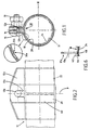
- the device comprises a sleeve 10 including two free ends, which extend substantially axially, are provided with assembly lips 12a and 12b. These lips delimit between them an axial slot 14 which, as shown in Figure 1, tends to close when the sleeve is tightened.
- the lips 12a and 12b in fact cooperate with means for tightening the sleeve which bring them closer to each other.
- these tightening means comprise a bolt comprising a screw 16 whose rod passes through two orifices 13a and 13b respectively formed in the lips 12a and 12b, and a nut 18 screwed onto this rod.
- the device which is used to connect two tubes having substantially the same diameter, can be placed around the opposite ends of these two tubes, ends shown in broken lines in the figure 2 and respectively designated by the references 20 and 22.
- the device further comprises a sealing ring 24 disposed in the sleeve 10 to surround the opposite ends of the two tubes 20 and 22.
- This ring is visible in FIG. 1.
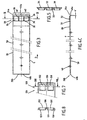
- the ring 24 is constituted by a flat strip 26, shown in Figures 3 to 5, which is rolled up on itself.
- the two longitudinal ends of the strip 26, 26a and 26b constitute two free edges which, when this strip is wound on itself to form the ring 24, are located opposite one on the other and are able to come into contact with one another when the ring being placed inside the sleeve, the latter is tightened around the ends of the tubes.
- the free edges 26a and 26b of the ring extend transversely to the longitudinal direction D of the strip 26.
- the ring has a region 28 called "deformable region". It can be seen that this region extends transversely over substantially the entire width l of the strip 26. In the longitudinal direction of the strip, the region 28 extends over a relatively small portion of the length L of the strip, by example between 3 and 10% and advantageously between 4 and 6% of the length L.
- the deformable region 28 team only the free edge 26a, which constitutes an advantageous arrangement.
- a deformable region could be provided in the vicinity of each of the two free edges 26a and 26b.
- the ring includes means to cause a deformation consisting of a decrease, in this region, of the length of the strip 26, when the free edges 26a and 26b are pressed against one another under the effect of the tightening of the sleeve 10 on the ends of the tubes 20 and 22.
- the deformable region extends over practically the entire width l of the strip, the deformation may not be uniform over this entire width l .
- the ring 24 located inside the sleeve 10 surrounds the ends of the two tubes, the latter each extend substantially over one of the two halves m1 and m2 of the width of the strip which constitutes the ring.
- the decrease in length in the deformable region 28 may be greater in one of the two halves m1 and m2 than in the other. Due to the ability of the region 28 to deform uniformly over the entire width l , the seal is therefore preserved even if the diameters of the two tubes are slightly different.
- the presence of the sealing ring obviously aims to create a closed space in the tube connection area, between the peripheries outer tubes and the inner periphery of the sealing ring.
- leaks may still occur in the area of tube connection at the deformable region of the ring.
- it includes means for trapping such leaks between at least one part of the deformable region of the ring and one of the two elements constituted by the internal periphery of the sleeve 10 and by the peripheries external of tubes 20 and 22.
- these means can include folds suitably arranged in the deformable region.
- the means for causing the deformation of the strip in the deformable region 28 comprise a series of perforations which extend over substantially the entire width l of the strip 26.
- this series comprises three perforations 30, 32 and 34 aligned in the transverse direction of the strip.
- the central perforation 32 is separated from the other two by two solid preserved areas 36 and 38.
- the series of perforations may include more perforations or, on the contrary, include only one or two. If several perforations are present, it is preferable that the separation zones between two adjacent perforations, such as zones 36 and 38, are sufficiently small or sufficiently thin to be able to easily deform during tightening.
- the perforations can, as in the example shown, be quadrangular, but they can also have any satisfactory shape, for example a circular shape.
- one of the perforations of the series is in the mating area of the ends tubes.
- this is the case of the central perforation 32 since the coupling area of the ends of the tubes is substantially in the median transverse plane P (plane of symmetry) of the Ring.
- the raised edge 33 can be produced in the same operation as the perforation 32.
- the raised edge 33 can cooperate with the internal periphery 11 of the sleeve.
- the border 33 is relatively flexible due to the weakness of its thickness e (for example from 5 to 30% of the thickness of the strip 26).
- the border 33 is therefore suitable coming into tight contact with the internal periphery 11 of the sleeve.
- the other perforations, 30 and 34 can also be provided with borders similar to border 33.
- the ring 24 is arranged in the sleeve, so that the perforations in the series of perforations are find with regard to a full part of the sleeve 10, that is to say that they are angularly offset relative to the axial slot 14.
- the device advantageously includes means for defining the position of the ring in the sleeve so that the free edges 26a and 26b of this ring are angularly offset with respect to the slot axial 14, as best seen on the magnifying glass in Figure 1.
- the perforations in the deformable region therefore close to one free edges, this precaution ensures that the perforations are angularly offset from slot 14.
- Such positioning means are visible in Figures 4 and 6. They comprise, for example, a stamped part 40 produced in the ring and radially projecting outward from the latter.
- the periphery of sleeve 10 has, for its part, a recess or a perforation 42, in which the stamp 40 is housed.
- the recess or the perforation 42 is made in a flap 44 which extends along the periphery of the nozzle 10 and which was preserved during the production by folding of the assembly lips 12a and 12a and of the cutout of one of the openings 13a and 13b of the latter.
- FIGS. 7 and 8 a second scenario, illustrated by FIGS. 7 and 8 and in which such deformability is not required, can also be selected.
- the strip 126 whose end is shown in FIG. 7 has a deformable region 128 which comprises a series of perforations comprising two perforations 130 and 132, which are separated by a part full 136.
- this second scenario is one where the series of perforations comprises at least two perforations separated by a solid part which is likely to be in the mating area of the ends of the tubes when the ring is placed inside the sleeve, itself arranged around the tubes. In this case, it is under the area 136 that leaks are likely to occur.
- the means for allowing the deformation of the strip in the deformable region may include a series of at least one thinned portion, that is to say a portion of which the thickness, measured transversely to the plane of the strip, is less than the thickness of this strip.
- the thinned portion has a thickness of between 10% and 40% of the thickness of the strip.
- these may each be provided with a sealing ring, 48a and 48b respectively. So when, under the effect of tightening, the edges free are pressed against each other, rods 48a and 48b come in tight contact.
- These rods are advantageously constituted by folds of the two free axial ends of the strip. These folds are preferably oblique, that is, they are oriented relative to the plane of the strip so as to go, each, away from the end longitudinal of the strip in which they are formed. We make sure that they lean directly against each other during the contact of the edges free from the ring.
- these the latter are less rigid than most of the ring.
- their thickness e ' is less than the thickness E of the strip and advantageously between 20 and 60% of this thickness.
- this ring has sealing rods 50, 150, disposed on each axial end of the ring, that is to say on each of the longitudinal edges of the strip which constitutes this ring and projecting towards the inside of the ring so to cooperate with the outer peripheries of the tubes.
- these sealing rods 50 or 150 are formed by folds of the edge of the ring, on the edges longitudinal of the strip which constitutes it, extending towards the inside of the Ring.
- the thickness of the folds 50 and 150 is advantageously significantly lower than that of the ring.
- All of the folds 50 (or 150), 48a and 48b therefore form a fold continuous which extends over the entire periphery of the strip which constitutes the Ring.
- this the latter has, on its internal periphery, a hollow area forming a housing for the ring.
- This recessed area is produced by a deep-drawn 60 substantially annular, projecting radially outward from the muff.
- the stampings 70 directed towards the inside of the ring, are used for wedging of the ends 20 and 22 of the tubes, one with respect to the other.
Landscapes
- Engineering & Computer Science (AREA)
- General Engineering & Computer Science (AREA)
- Mechanical Engineering (AREA)
- Joints With Sleeves (AREA)
- Gasket Seals (AREA)
Abstract
Description
La présente invention concerne un dispositif d'accouplement étanche de deux tubes lisses disposés bout à bout, ayant sensiblement le même diamètre.The present invention relates to a coupling device waterproof of two smooth tubes arranged end to end, having substantially the same diameter.
On connaít déjà, par le document FR-A-2 662 486, un dispositif selon le preambule de la revendication 1.We already know, from document FR-A-2 662 486, a device according to the preamble of claim 1.
Des dispositifs de ce type servent par exemple au raccord bout à bout de deux tubes d'échappement. Les exigences en matière d'étanchéité du raccord sont de plus en plus grandes. On a naturellement tendance à penser que plus on serre le manchon sur les tubes, plus l'étanchéité est améliorée. Le problème est que, lorsque l'on serre le manchon, on diminue le diamètre de la bague d'étanchéité, ce qui rapproche ces deux bords libres l'un de l'autre. Il faut donc que la jonction entre les deux bords libres soit aussi étanche que possible et que le fait de serrer davantage le manchon à partir du moment où les deux bords libres sont en contact n'occasionne pas de chevauchement nuisible à l'étanchéité.Devices of this type are used for example for the butt connection two exhaust pipes. The sealing requirements of the fitting are getting bigger. We naturally tend to think that the more we tightens the sleeve on the tubes, the more the sealing is improved. The problem is when the sleeve is tightened, the diameter of the ring is reduced sealing, which brings these two free edges together. So it is necessary that the junction between the two free edges is as tight as possible and that the fact tighten the sleeve further from the moment the two free edges are in contact does not cause overlapping detrimental to sealing.
Le document FR-A-2 662 486 propose une première solution à ce problème en réalisant les bords libres de la bague en biseau, de telle sorte que ceux-ci peuvent être appliqués l'un contre l'autre et se décaler transversalement l'un par rapport à lorsque le diamètre de la bague diminue. Cette solution est globalement satisfaisante, mais elle ne permet pas de maítriser totalement l'appui des deux bords libres l'un contre l'autre ni d'assurer le calage de la bague à l'intérieur du manchon.Document FR-A-2 662 486 proposes a first solution to this problem by making the free edges of the ring beveled, so that these can be applied against each other and shift transversely one compared to when the diameter of the ring decreases. This solution is generally satisfactory, but it does not fully control the support of the two free edges one against the other nor of securing the ring to inside the sleeve.
De plus, en raison des tolérances de fabrication, il arrive que les diamètres des deux tubes lisses que l'on raccorde soient très légèrement différents. Il faut donc que la bague puisse s'adapter à cette légère différence de diamètre, ce qui n'est pas le cas dans la solution citée précédemment. In addition, due to manufacturing tolerances, it may happen that diameters of the two smooth tubes that are connected are very slightly different. The ring must therefore be able to adapt to this slight difference in diameter, which is not the case in the solution cited above.
Le document FR-A-2 689 204 montre un dispositif dans lequel la bague d'étanchéité présente des bords libres conformés de manière à s'emboíter en chicane. Plus précisément, un bord libre présente au moins une encoche axiale, tandis que l'autre bord libre présente au moins une languette axiale de forme complémentaire. Lorsque la languette est insérée dans l'encoche, il y a peut-être un contact entre les bords de la languette et ceux de l'encoche mais, même en serrant la manchon, on ne peut pas assurer un effort d'appui entre la languette et l'encoche, Les zones de contact sont très localisées et peu sûres du point de vue de l'étanchéité. Document FR-A-2 689 204 shows a device in which the sealing ring has free edges shaped so as to fit in chicane. More specifically, a free edge has at least one axial notch, while the other free edge has at least one axial shaped tongue complementary. When the tab is inserted into the notch, there may be a contact between the edges of the tongue and those of the notch but, even when tightening the sleeve, it is not possible to ensure a bearing force between the tongue and the notch, The contact areas are very localized and insecure from the point of view of sealing.
La présente invention a pour but d'améliorer encore le dispositif d'accouplement et de remédier aux inconvénients précités.The present invention aims to further improve the device coupling and remedy the aforementioned drawbacks.
Ce but est atteint par les caractéristiques de la partie caractérisante de la revendication 1.This goal is achieved by the characteristics of the game Characterizing of claim 1.
Grâce à cette conformation, les bords libres transversaux de la bague d'étanchéité sont automatiquement appliqués l'un contre l'autre lorsque l'on serre le manchon. De plus, lorsque l'on continue de serrer le manchon, la longueur de la bande qui constitue la bague peut diminuer dans la région déformable, de telle sorte que le diamètre de cette bague peut diminuer sans chevauchement de ses bords libres. Par ailleurs, la région déformable s'étendant sur sensiblement la totalité la largeur de la bande, cette dernière peut s'adapter à de légères différences de diamètre des deux tubes à raccorder, puisque la longueur de la bande peut être plus grande dans une partie de la région déformable que dans une autre.Thanks to this conformation, the transverse free edges of the sealing ring are automatically applied against each other when you tighten the sleeve. In addition, when you continue to tighten the sleeve, the length of the band which constitutes the ring may decrease in the deformable region, so that the diameter of this ring can decrease without overlapping its free edges. In addition, the region deformable extending over substantially the entire width of the strip, the latter can adapt to slight differences in diameter of the two tubes to be connected, since the length of the strip can be longer in part of the deformable region than in another.
De manière avantageuse, le dispositif comporte des moyens pour emprisonner les fuites susceptibles de se produire dans la zone d'accouplement des extrémités des tubes entre au moins une portion de la région déformable de la bague et l'un des deux éléments constitués par la périphérie interne du manchon et par les périphéries externes des tubes.Advantageously, the device comprises means for trap any leaks that may occur in the mating area tube ends between at least a portion of the region deformable ring and one of the two elements constituted by the periphery internal of the sleeve and by the external peripheries of the tubes.
Les moyens pour provoquer une déformation dans la région déformable peuvent comprendre une série de perforations ou, en variante, une série de portions amincies.Means to cause deformation in the region deformable may include a series of perforations or, alternatively, a series of thinned portions.
La bague d'étanchéité présente avantageusement un jonc d'étanchéité qui fait saillie vers l'intérieur de cette bague est apte à coopérer avec les périphéries externes des tubes. De préférence, ce jonc est constitué par un repli de la bordure de la bague vers l'intérieur. The sealing ring advantageously has a ring sealing which protrudes towards the inside of this ring is able to cooperate with the outer peripheries of the tubes. Preferably, this rod is made up by folding the edge of the ring inward.
L'invention sera bien comprise et ses avantages apparaítront mieux à la lecture de la description détaillée qui suit, de modes de réalisation représentés à titre d'exemples non limitatifs.The invention will be well understood and its advantages will appear better on reading the following detailed description of modes of embodiment represented by way of nonlimiting examples.
La description se réfère aux dessins annexés, sur lesquels :
- la figure 1 est une vue de côté du dispositif, sans les tubes susceptibles d'être disposés à l'intérieur, avec une loupe montrant un détail,
- la figure 2 est une vue en élévation extérieure du manchon, selon la flèche II de la figure 1,
- la figure 3 est une vue en élévation de la bande qui constitue la bague, cette bande étant représentée à plat,
- la figure 4 est une vue de dessus de la figure 3,
- la figure 5 est une coupe selon la ligne V-V de la figure 3,
- la figure 6 est une vue partielle en coupe dans le plan transversal médian du dispositif, montrant le détail VI de la figure 1,
- la figure 7 est une vue partielle de dessus de la bande montrant une variante, et
- la figure 8 est une vue en coupe selon la ligne VIII-VIII de la figure 7.
- FIG. 1 is a side view of the device, without the tubes capable of being placed inside, with a magnifying glass showing a detail,
- FIG. 2 is an external elevation view of the sleeve, according to arrow II in FIG. 1,
- FIG. 3 is an elevation view of the strip which constitutes the ring, this strip being shown flat,
- FIG. 4 is a top view of FIG. 3,
- FIG. 5 is a section along the line VV in FIG. 3,
- FIG. 6 is a partial view in section in the median transverse plane of the device, showing the detail VI of FIG. 1,
- FIG. 7 is a partial top view of the strip showing a variant, and
- FIG. 8 is a sectional view along line VIII-VIII of FIG. 7.
En se reportant tout d'abord aux figures 1 et 2, on voit que le
dispositif comporte un manchon 10 dont deux extrémités libres, qui
s'étendent sensiblement axialement, sont pourvues de lèvres d'assemblage
12a et 12b. Ces lèvres délimitent entre elles une fente axiale 14 qui, comme
le montre la figure 1, tend à se refermer lorsque l'on serre le manchon. Les
lèvres 12a et 12b coopèrent en effet avec des moyens de serrage du
manchon qui les rapprochent l'une de l'autre. Dans l'exemple représenté, ces
moyens de serrage comportent un boulon comprenant une vis 16 dont la tige
passe à travers deux orifices 13a et 13b respectivement ménagés dans les
lèvres 12a et 12b, et un écrou 18 vissé sur cette tige.Referring first to Figures 1 and 2, we see that the
device comprises a
Le dispositif, qui sert à raccorder deux tubes ayant sensiblement
le même diamètre, peut être disposé autour des extrémités en regard de ces
deux tubes, extrémités représentées en traits mixtes interrompus sur la figure
2 et respectivement désignées par les références 20 et 22.The device, which is used to connect two tubes having substantially
the same diameter, can be placed around the opposite ends of these
two tubes, ends shown in broken lines in the figure
2 and respectively designated by the
Le dispositif comprend, en outre, une bague d'étanchéité 24
disposée dans le manchon 10 pour entourer les extrémités en regard des
deux tubes 20 et 22. Cette bague est visible sur la figure 1. La bague 24 est
constituée par une bande plate 26, représentée sur les figures 3 à 5, qui est
enroulée sur elle-même. Les deux extrémités longitudinales de la bande 26,
26a et 26b, constituent deux bords libres qui, lorsque cette bande est
enroulée sur elle-même pour former la bague 24, sont situés en regard l'un
de l'autre et sont aptes à venir en contact l'un contre l'autre lorsque, la bague
étant disposée à l'intérieur du manchon, ce dernier est serré autour des
extrémités des tubes.The device further comprises a
Les bords libres 26a et 26b de la bague s'étendent
transversalement à la direction longitudinale D de la bande 26. Au voisinage
du bord libre 26a, la bague comporte une région 28 dite "région
déformable". On voit que cette région s'étend transversalement sur
sensiblement la totalité de la largeur l de la bande 26. Dans le sens
longitudinal de la bande, la région 28 s'étend sur une portion relativement
faible de la longueur L de la bande, par exemple comprise entre 3 et 10 % et
avantageusement entre 4 et 6 % de la longueur L.The
Dans l'exemple représenté, la région déformable 28 équipe
seulement le bord libre 26a, ce qui constitue une disposition avantageuse.
Toutefois, on pourrait prévoir une région déformable au voisinage de
chacun des deux bords libres 26a et 26b.In the example shown, the
Dans la région déformable 28, la bague comporte des moyens
pour provoquer une déformation consistant en une diminution, dans cette
région, de la longueur de la bande 26, lorsque les bords libres 26a et 26b
sont sollicités en appui l'un contre l'autre sous l'effet du serrage du manchon
10 sur les extrémités des tubes 20 et 22.In the
Ainsi, c'est pratiquement uniquement dans la région déformable que se produit cette déformation, la plus grande partie de la bague n'étant pas affectée.So it's practically only in the deformable region that this deformation occurs, most of the ring being not affected.
La région déformable s'étendant sur pratiquement toute la largeur
l de la bande, la déformation peut ne pas être uniforme sur toute cette
largeur l. Lorsque la bague 24 située à l'intérieur du manchon 10 enserre les
extrémités des deux tubes, ces derniers s'étendent sensiblement chacun sur
l'une des deux moitiés m1 et m2 de la largeur de la bande qui constitue la
bague. Ainsi, si les diamètres externes des deux tubes 20 et 22 sont très
légèrement différents, la diminution de longueur dans la région déformable
28 peut être plus importante dans l'une des deux moitiés m1 et m2 que dans
l'autre. Du fait de la capacité de la région 28 à se déformer non
uniformément sur la totalité de la largeur l, l'étanchéité est donc préservée
même si les diamètres des deux tubes sont légèrement différents.Since the deformable region extends over practically the entire width l of the strip, the deformation may not be uniform over this entire width l . When the
La présence de la bague d'étanchéité vise évidemment à créer un
espace fermé dans la zone de raccordement des tubes, entre les périphéries
externes des tubes et la périphérie interne de la bague d'étanchéité.
Toutefois, des fuites risquent tout de même de se produire dans la zone de
raccordement des tubes, au niveau de la région déformable de la bague. Pour
éviter que ces fuites ne nuisent à l'étanchéité globale du dispositif, celui-ci
comporte des moyens pour emprisonner de telles fuites entre au moins une
partie de la région déformable de la bague et l'un des deux éléments
constitués par la périphérie interne du manchon 10 et par les périphéries
externes des tubes 20 et 22. On verra dans la suite que ces moyens peuvent
comprendre des replis convenablement disposés dans la région déformable.The presence of the sealing ring obviously aims to create a
closed space in the tube connection area, between the peripheries
outer tubes and the inner periphery of the sealing ring.
However, leaks may still occur in the area of
tube connection at the deformable region of the ring. For
prevent these leaks from affecting the overall tightness of the device, it
includes means for trapping such leaks between at least one
part of the deformable region of the ring and one of the two elements
constituted by the internal periphery of the
Dans le mode de réalisation représenté, les moyens pour
provoquer la déformation de la bande dans la région déformable 28
comprennent une série de perforations qui s'étend sur sensiblement la
totalité de la largeur l de la bande 26. Dans l'exemple représenté, cette série
comprend trois perforations 30, 32 et 34 alignées dans le sens transversal de
la bande. La perforation centrale 32 est séparée des deux autres par deux
zones pleines préservées 36 et 38. La série de perforations peut comprendre
davantage de perforations ou, au contraire, n'en comprendre qu'une ou deux.
Si plusieurs perforations sont présentes, il est préférable que les zones de
séparation entre deux perforations adjacentes, telles que les zones 36 et 38,
soient suffisamment peu larges ou suffisamment peu épaisses pour pouvoir
se déformer facilement lors du serrage. Les perforations peuvent, comme
dans l'exemple représenté, être quadrangulaires, mais elles peuvent
également avoir toute forme satisfaisante, par exemple une forme circulaire.In the embodiment shown, the means for causing the deformation of the strip in the
Différents cas de figure sont possibles quant à la position des
perforations par rapport à la zone précise de raccordement des extrémités
libres des deux tubes. En effet, dans un premier cas de figure, l'une des
perforations de la série se trouve dans la zone d'accouplement des extrémités
des tubes. Dans l'exemple représenté, c'est le cas de la perforation centrale
32 puisque la zone d'accouplement des extrémités des tubes se trouve
sensiblement dans le plan transversal médian P (plan de symétrie) de la
bague. Different cases are possible as for the position of the
perforations in relation to the precise end connection area
free from the two tubes. Indeed, in a first case, one of the
perforations of the series is in the mating area of the ends
tubes. In the example shown, this is the case of the
Dans ce cas, les fuites entre les deux extrémités en regard des
tubes 20 et 22 risquent évidemment de sortir par la perforation 32. C'est
alors entre la partie de la bague voisine de la perforation 32 et la périphérie
interne 11 du manchon 10 qu'il convient d'emprisonner ces fuites. A cet
effet, une bordure 33 qui est relevée vers l'extérieur de la bague s'étend sur
tout le pourtour de l'ouverture 32. Le sens vers l'extérieur est évidemment
celui qui s'éloigne du centre géométrique de la bague lorsque la bande est
enroulée sur elle-même.In this case, the leaks between the two ends opposite the
La bordure relevée 33 peut être réalisée dans la même opération
que la perforation 32. Lorsque la bague est située à l'intérieur du manchon et
lorsque celui-ci est serré sur les tubes, la bordure relevée 33 peut coopérer
avec la périphérie interne 11 du manchon. La bordure 33 est relativement
souple du fait de la faiblesse de son épaisseur e (par exemple de 5 à 30 % de
l'épaisseur de la bande 26). Lorsque, le manchon étant serré autour du tube,
la bague est elle-même serrée dans ce manchon, la bordure 33 est donc apte
à venir en contact étanche avec la périphérie interne 11 du manchon. Les
autres perforations, 30 et 34, peuvent également être munie de bordures
analogues à la bordure 33.The raised
Il doit être entendu que la bague 24 est disposée dans le
manchon, de telle sorte que les perforations de la série de perforations se
trouvent au regard d'une partie pleine du manchon 10, c'est-à-dire qu'elles
sont décalées angulairement par rapport à la fente axiale 14.It should be understood that the
Ainsi, pour assurer un positionnement correct de la bague dans le
manchon, le dispositif comporte avantageusement des moyens pour définir
la position de la bague dans le manchon de telle sorte que les bords libres
26a et 26b de cette bague soient angulairement décalés par rapport à la fente
axiale 14, comme on le voit mieux sur la loupe de la figure 1. Les
perforations se trouvant dans la région déformable, donc à proximité de l'un
des bords libres, cette précaution permet de faire en sorte que les
perforations soient angulairement décalées par rapport à la fente 14.Thus, to ensure correct positioning of the ring in the
sleeve, the device advantageously includes means for defining
the position of the ring in the sleeve so that the
De tels moyens de positionnement sont visibles sur les figures 4
et 6. Ils comportent par exemple un embouti 40 réalisé dans la bague et
faisant radialement saillie vers l'extérieur de cette dernière. La périphérie du
manchon 10 comporte, quant à elle, un renfoncement ou une perforation 42,
dans lequel vient se loger l'embouti 40. De préférence, le renfoncement ou la
perforation 42 est pratiqué dans une bavette 44 qui s'étend selon la
périphérie de l'embout 10 et qui a été préservée lors de la réalisation par
repli des lèvres d'assemblage 12a et 12a et de la découpe de l'une des
ouvertures 13a et 13b de ces dernières.Such positioning means are visible in Figures 4
and 6. They comprise, for example, a stamped
Ce premier cas de figure, dans lequel la perforation 32 se trouve
dans la zone d'accouplement des extrémités des tubes et est munie de sa
bordure 33 relevée vers l'extérieur, constitue une disposition avantageuse
puisqu'elle est compatible avec la présence d'une ou plusieurs perforations
larges, ce qui confère à la bande une grande capacité à se déformer dans la
région 28.This first case, in which the
Toutefois, un deuxième cas de figure, illustré par les figures 7 et
8 et dans lequel une telle déformabilité n'est pas requise, peut également être
choisi. La bande 126 dont l'extrémité est représentée sur la figure 7 présente
une région déformable 128 qui comporte une série de perforations
comprenant deux perforations 130 et 132, qui sont séparées par une partie
pleine 136. De manière générale, ce deuxième cas de figure est celui où la
série de perforations comporte au moins deux perforations séparées par une
partie pleine qui est susceptible de se trouver dans la zone d'accouplement
des extrémités des tubes lorsque la bague est mise en place à l'intérieur du
manchon, lui-même disposé autour des tubes. Dans ce cas, c'est sous la
zone 136 que sont susceptibles de se produire des fuites. Pour préserver
l'étanchéité du système, ces fuites sont emprisonnées entre la périphérie
interne de la bague et les périphéries externes des tubes grâce au fait que les
perforations 130 et 132 présentent toutes deux des bordures, respectivement
131 et 133, qui sont retournées vers l'intérieur de la bague et sont ainsi aptes
à coopérer avec les périphéries externes des tubes. Ainsi, lorsque le
manchon muni de la bague est serré sur les tubes, les bordures 131 et 133
peuvent venir en contact étanche avec les périphéries externes des tubes. Ce
contact étanche est d'autant mieux assuré que les bordures 131 et 133 sont
relativement déformables du fait de la faiblesse de leur épaisseur respective.However, a second scenario, illustrated by FIGS. 7 and
8 and in which such deformability is not required, can also be
selected. The
Selon une variante non représentée, les moyens pour permettre la déformation de la bande dans la région déformable peuvent comprendre une série d'au moins une portion amincie, c'est-à-dire une portion dont l'épaisseur, mesurée transversalement au plan de la bande, est inférieure à l'épaisseur de cette bande. De préférence, pour que sa déformabilité soit suffisante, la portion amincie présente une épaisseur comprise entre 10 % et 40 % de l'épaisseur de la bande. According to a variant not shown, the means for allowing the deformation of the strip in the deformable region may include a series of at least one thinned portion, that is to say a portion of which the thickness, measured transversely to the plane of the strip, is less than the thickness of this strip. Preferably, so that its deformability is sufficient, the thinned portion has a thickness of between 10% and 40% of the thickness of the strip.
Pour parfaire le contact étanche entre les deux bords libres 26a et
26b de la bague, ceux-ci peuvent être munis, chacun, d'un jonc d'étanchéité,
respectivement 48a et 48b. Ainsi, lorsque, sous l'effet du serrage, les bords
libres sont sollicités en appui l'un contre l'autre, les joncs 48a et 48b
viennent en contact étanche. Ces joncs sont avantageusement constitués par
des replis des deux extrémités axiales libres de la bande. Ces replis sont de
préférence obliques, c'est-à-dire qu'ils sont orientés par rapport au plan de
la bande de manière à aller, chacun, en s'éloignant de l'extrémité
longitudinale de la bande dans laquelle ils sont ménagés. On s'assure ainsi
qu'ils s'appuient directement l'un contre l'autre lors du contact des bords
libres de la bague.To perfect the tight contact between the two
Pour assurer un contact étanche entre les replis 48a et 48b, ces
dernier sont moins rigides que la majeure partie de la bague. A cet effet, leur
épaisseur e' est inférieure à l'épaisseur E de la bande et avantageusement
comprise entre 20 et 60 % de cette épaisseur.To ensure tight contact between the
De même, pour assurer globalement un contact étanche entre la
bague d'étanchéité et les périphéries externes des tubes, cette bague présente
des joncs d'étanchéité 50, 150, disposés sur chacune extrémités axiales de la
bague, c'est-à-dire sur chacun des bords longitudinaux de la bande qui
constitue cette bague et faisant saillie vers l'intérieur de la bague de manière
à coopérer avec les périphéries externes des tubes. Comme ceux des bords
libres transversaux 26a et 26b, ces joncs d'étanchéité 50 ou 150 sont
constitués par des replis de la bordure de la bague, sur les bords
longitudinaux de la bande qui la constitue, s'étendant vers l'intérieur de la
bague. De même que celle des replis 48a et 48b, l'épaisseur des replis 50 et
150 est avantageusement nettement inférieure à celle de la bague.Likewise, to ensure overall tight contact between the
sealing ring and the outer peripheries of the tubes, this ring has
sealing
L'ensemble des replis 50 (ou 150), 48a et 48b forme donc un repli continu qui s'étend sur la totalité du pourtour de la bande qui constitue la bague.All of the folds 50 (or 150), 48a and 48b therefore form a fold continuous which extends over the entire periphery of the strip which constitutes the Ring.
Pour caler axialement la bague 26 à l'intérieur du manchon 10, ce
dernier présente, sur sa périphérie interne, une zone en creux formant un
logement pour la bague. Cette zone en creux est réalisée par un embouti 60
sensiblement annulaire, faisant radialement saillie vers l'extérieur du
manchon.To axially wedge the
Les emboutis 70, dirigés vers l'intérieur de la bague, servent au
calage des extrémités 20 et 22 des tubes, l'une par rapport à l'autre.The stampings 70, directed towards the inside of the ring, are used for
wedging of the
Claims (9)
- Device for the sealed coupling of two plain tubes (20, 22) arranged end to end and having roughly the same diameter, the device comprising a sleeve (10) which can be placed around the facing ends of the two tubes, this sleeve having two free ends provided with assembly lips (12a, 12b) which between them delimit an axial slot (14), the assembly lips being able to collaborate with sleeve-clamping means (16, 18) capable of pulling the said lips (12a, 12b) together, the device further comprising a sealing ring (24) which can be placed inside the sleeve to surround the facing ends of the two tubes, this ring consisting of a flat band (26, 126) wound up on itself and having two free edges (26a, 26b) facing one another and running transversely to the longitudinal direction (D) of the band (26, 126) that forms this ring, these free edges having contacting surfaces able to come into contact with one another when, with the ring (24) located in the sleeve (10), the latter is clamped around the facing ends of the tubes (20, 22),
characterized in that the free edges (26a, 26b) of the sealing ring form the said contacting surfaces which run transversely to the longitudinal direction (D) of the band and in that the ring (24), at least in one region (28, 128) known as a "deformable region" located near one (26a) of the free edges of the ring and extending over roughly the entire width (l) of the band (26) that forms this ring, comprises means for causing deformation consisting in a reduction, in the said deformable region, of the length (L) of the band which forms the ring when the free edges (26a, 26b) thereof are forced against one another under the effect of the clamping of the sleeve (10) onto the ends of the tubes (20, 22). - Device according to Claim 1, characterized in that it comprises means for trapping leaks that may arise in the region of coupling of the ends (20, 22) of the tubes between at least one portion of the deformable region (28, 128) of the ring (24) and one of the two elements which consist of the interior periphery (11) of the sleeve (10) and of the exterior peripheries of the tubes (20, 22).
- Device according to Claim 1 or 2, characterized in that the sealing ring (24) in the deformable region (28, 128) has a series of perforations (30, 32, 34; 130, 132) comprising at least one perforation.
- Device according to Claims 2 and 3, characterized in that the series of perforations (30, 32, 34) comprises one perforation (32) capable of lying in the region of coupling of the ends of the tubes (20, 22), and in that at least this perforation (32) has an edging (33) which is raised towards the outside of the ring and able to collaborate with the interior periphery (11) of the sleeve (10).
- Device according to Claims 2 and 3, characterized in that the series of perforations comprises at least two perforations (130, 132) separated by a solid part (136) which is able to lie in the region of coupling of the ends of the tubes (20, 22) and in that these perforations have edgings (131, 133) turned up towards the inside of the ring and able to collaborate with the exterior peripheries of the tubes (20, 22).
- Device according to Claim 1 or 2, characterized in that the sealing ring in the deformable region has a series of thinned portions comprising at' least one thinned portion.
- Device according to any one of Claims 1 to 6, characterized in that the sealing ring (24) has ring seals (48a, 48b, 50; 150) projecting towards the inside of this ring and able to collaborate with the exterior peripheries of the tubes (20, 22).
- Device according to Claim 7, characterized in that the ring seals (48a, 48b, 50 ; 150) are formed by a continuous fold, directed towards the inside of the ring (24) and extending around the entire periphery of the band (26, 126) that forms this ring.
- Device according to any one of Claims 1 to 8, characterized in that it comprises means for defining the position of the ring (24) in the sleeve (10) so that the free edges (26a, 26b) of this ring are angularly offset from the axial slot (14) of the sleeve (10).
Applications Claiming Priority (2)
| Application Number | Priority Date | Filing Date | Title |
|---|---|---|---|
| FR9605905 | 1996-05-13 | ||
| FR9605905A FR2748542B1 (en) | 1996-05-13 | 1996-05-13 | DEVICE FOR THE SEALED COUPLING OF TWO SMOOTH TUBES |
Publications (2)
| Publication Number | Publication Date |
|---|---|
| EP0807780A1 EP0807780A1 (en) | 1997-11-19 |
| EP0807780B1 true EP0807780B1 (en) | 2002-03-20 |
Family
ID=9492061
Family Applications (1)
| Application Number | Title | Priority Date | Filing Date |
|---|---|---|---|
| EP19970401049 Expired - Lifetime EP0807780B1 (en) | 1996-05-13 | 1997-05-12 | Device for sealingly connecting two flat pipes |
Country Status (4)
| Country | Link |
|---|---|
| EP (1) | EP0807780B1 (en) |
| DE (1) | DE69711116T2 (en) |
| ES (1) | ES2173403T3 (en) |
| FR (1) | FR2748542B1 (en) |
Families Citing this family (2)
| Publication number | Priority date | Publication date | Assignee | Title |
|---|---|---|---|---|
| FR2794517B1 (en) | 1999-06-02 | 2001-08-24 | Caillau Ets | DEVICE FOR THE SEALED CONNECTION OF TWO SMOOTH TUBES |
| DE20210323U1 (en) | 2002-07-04 | 2002-09-26 | HJS Fahrzeugtechnik GmbH & Co., 58706 Menden | pipe connectors |
Family Cites Families (4)
| Publication number | Priority date | Publication date | Assignee | Title |
|---|---|---|---|---|
| US2227551A (en) * | 1939-06-07 | 1941-01-07 | Jolly L Morris | Pipe coupling and pipe clamp |
| US3700008A (en) * | 1971-05-28 | 1972-10-24 | Mueller Co | Pipe clamp with improved gap bridge |
| FR2689204A1 (en) * | 1992-03-25 | 1993-10-01 | Lupan Ag | Assembly collar, intended for the butt connection of tubes. |
| DE9207960U1 (en) * | 1992-06-13 | 1992-09-10 | KOMTEC GmbH Kommunikationstechnische Anlagen, 7060 Schorndorf | Device for connecting two pipe sockets |
-
1996
- 1996-05-13 FR FR9605905A patent/FR2748542B1/en not_active Expired - Fee Related
-
1997
- 1997-05-12 ES ES97401049T patent/ES2173403T3/en not_active Expired - Lifetime
- 1997-05-12 EP EP19970401049 patent/EP0807780B1/en not_active Expired - Lifetime
- 1997-05-12 DE DE69711116T patent/DE69711116T2/en not_active Expired - Fee Related
Also Published As
| Publication number | Publication date |
|---|---|
| DE69711116T2 (en) | 2002-11-07 |
| EP0807780A1 (en) | 1997-11-19 |
| FR2748542A1 (en) | 1997-11-14 |
| ES2173403T3 (en) | 2002-10-16 |
| FR2748542B1 (en) | 1998-07-31 |
| DE69711116D1 (en) | 2002-04-25 |
Similar Documents
| Publication | Publication Date | Title |
|---|---|---|
| EP3217059B1 (en) | Tightening system comprising a collar and isolated pre-mounting clips | |
| EP0161149B1 (en) | Sealing device | |
| EP1497582B1 (en) | Impervious connecting device, in particular for the engine air inlet system of a motor vehicle | |
| EP2310734B1 (en) | Tightening device with collar | |
| FR2761956A1 (en) | PACKET COMPRISING ADDITIONAL CLOSING CLOSURE PROFILES | |
| EP0458700B1 (en) | Sealed butt end joining of two smooth pipes | |
| EP1181477B1 (en) | Device for sealed connection between two smooth tubes | |
| EP3670988B1 (en) | Clamping device comprising a belt and a sealing ring | |
| FR2605708A1 (en) | TIGHTENING NECKLACE WITHOUT EARS | |
| EP3901507B1 (en) | Tightening system for connecting pipes, comprising a collar and a washer having supporting tabs | |
| EP0280598B1 (en) | Hose clamp with an elasticity reserve | |
| EP0807780B1 (en) | Device for sealingly connecting two flat pipes | |
| FR3108960A1 (en) | Clamping system for the connection of tubes, comprising a collar and a washer carrying support brackets | |
| FR2891889A1 (en) | End piece for sealed connect coupling, has rear edge presenting female configuration comprising annular groove and annular protection wall extending towards rear from outer edge of annular groove | |
| EP3734130B1 (en) | Tightening device comprising a sealing gasket and assembly comprising such a device | |
| FR2957399A1 (en) | QUICK CONNECTOR WITH INSERTIONABLE PIPE IN A FITTING, AND METHOD OF CONNECTING THIS PIPE TO THIS FITTING | |
| EP1875116B1 (en) | Device for sealed coupling of two smooth tubes | |
| EP0675989B1 (en) | Device for assembling two profiled sections and profiled sections with a male and/or female profile | |
| EP0156736A1 (en) | Profiled sealing joint, particularly for sealing sliding vehicle doors | |
| FR2792975A1 (en) | Articulated clamping ring for cylindrical tubes or pipes | |
| EP2237385B1 (en) | Cable grommet fitting | |
| FR2627572A1 (en) | Flanged, bolted flexibly sealed pipe joint - has flange of ribbed, conical segments first bolted into ring and then axially, to squeeze flexible seal on to pipe end cover | |
| FR2943747A1 (en) | Hose clamp assembly for locking e.g. smooth end lug against outer surface of tube of tubular joint, has maintaining unit for maintaining connection element in loop along direction, in autonomous manner, even in absence of traction element | |
| FR2659415A1 (en) | Quick connector | |
| FR2785966A1 (en) | CONNECTING AND MAINTAINING CLIP FOR TWO TIGHTENING COLLARS |
Legal Events
| Date | Code | Title | Description |
|---|---|---|---|
| PUAI | Public reference made under article 153(3) epc to a published international application that has entered the european phase |
Free format text: ORIGINAL CODE: 0009012 |
|
| AK | Designated contracting states |
Kind code of ref document: A1 Designated state(s): DE ES GB IT |
|
| 17P | Request for examination filed |
Effective date: 19980121 |
|
| 17Q | First examination report despatched |
Effective date: 19991208 |
|
| GRAG | Despatch of communication of intention to grant |
Free format text: ORIGINAL CODE: EPIDOS AGRA |
|
| GRAG | Despatch of communication of intention to grant |
Free format text: ORIGINAL CODE: EPIDOS AGRA |
|
| GRAH | Despatch of communication of intention to grant a patent |
Free format text: ORIGINAL CODE: EPIDOS IGRA |
|
| GRAH | Despatch of communication of intention to grant a patent |
Free format text: ORIGINAL CODE: EPIDOS IGRA |
|
| REG | Reference to a national code |
Ref country code: GB Ref legal event code: IF02 |
|
| GRAA | (expected) grant |
Free format text: ORIGINAL CODE: 0009210 |
|
| AK | Designated contracting states |
Kind code of ref document: B1 Designated state(s): DE ES GB IT |
|
| REF | Corresponds to: |
Ref document number: 69711116 Country of ref document: DE Date of ref document: 20020425 |
|
| GBT | Gb: translation of ep patent filed (gb section 77(6)(a)/1977) |
Effective date: 20020624 |
|
| REG | Reference to a national code |
Ref country code: ES Ref legal event code: FG2A Ref document number: 2173403 Country of ref document: ES Kind code of ref document: T3 |
|
| PLBE | No opposition filed within time limit |
Free format text: ORIGINAL CODE: 0009261 |
|
| STAA | Information on the status of an ep patent application or granted ep patent |
Free format text: STATUS: NO OPPOSITION FILED WITHIN TIME LIMIT |
|
| 26N | No opposition filed |
Effective date: 20021223 |
|
| PGFP | Annual fee paid to national office [announced via postgrant information from national office to epo] |
Ref country code: ES Payment date: 20080522 Year of fee payment: 12 Ref country code: DE Payment date: 20080514 Year of fee payment: 12 |
|
| PGFP | Annual fee paid to national office [announced via postgrant information from national office to epo] |
Ref country code: IT Payment date: 20080520 Year of fee payment: 12 |
|
| PGFP | Annual fee paid to national office [announced via postgrant information from national office to epo] |
Ref country code: GB Payment date: 20080506 Year of fee payment: 12 |
|
| GBPC | Gb: european patent ceased through non-payment of renewal fee |
Effective date: 20090512 |
|
| PG25 | Lapsed in a contracting state [announced via postgrant information from national office to epo] |
Ref country code: GB Free format text: LAPSE BECAUSE OF NON-PAYMENT OF DUE FEES Effective date: 20090512 |
|
| PG25 | Lapsed in a contracting state [announced via postgrant information from national office to epo] |
Ref country code: DE Free format text: LAPSE BECAUSE OF NON-PAYMENT OF DUE FEES Effective date: 20091201 |
|
| REG | Reference to a national code |
Ref country code: ES Ref legal event code: FD2A Effective date: 20090513 |
|
| PG25 | Lapsed in a contracting state [announced via postgrant information from national office to epo] |
Ref country code: ES Free format text: LAPSE BECAUSE OF NON-PAYMENT OF DUE FEES Effective date: 20090513 |
|
| PG25 | Lapsed in a contracting state [announced via postgrant information from national office to epo] |
Ref country code: IT Free format text: LAPSE BECAUSE OF NON-PAYMENT OF DUE FEES Effective date: 20090512 |