EP3734026B1 - Gasturbinenmotorjoch und bauträger - Google Patents
Gasturbinenmotorjoch und bauträger Download PDFInfo
- Publication number
- EP3734026B1 EP3734026B1 EP20172547.0A EP20172547A EP3734026B1 EP 3734026 B1 EP3734026 B1 EP 3734026B1 EP 20172547 A EP20172547 A EP 20172547A EP 3734026 B1 EP3734026 B1 EP 3734026B1
- Authority
- EP
- European Patent Office
- Prior art keywords
- yoke
- gas turbine
- turbine engine
- component
- mounting
- Prior art date
- Legal status (The legal status is an assumption and is not a legal conclusion. Google has not performed a legal analysis and makes no representation as to the accuracy of the status listed.)
- Active
Links
Images

Classifications
-
- F—MECHANICAL ENGINEERING; LIGHTING; HEATING; WEAPONS; BLASTING
- F01—MACHINES OR ENGINES IN GENERAL; ENGINE PLANTS IN GENERAL; STEAM ENGINES
- F01D—NON-POSITIVE DISPLACEMENT MACHINES OR ENGINES, e.g. STEAM TURBINES
- F01D25/00—Component parts, details, or accessories, not provided for in, or of interest apart from, other groups
- F01D25/28—Supporting or mounting arrangements, e.g. for turbine casing
- F01D25/285—Temporary support structures, e.g. for testing, assembling, installing, repairing; Assembly methods using such structures
-
- B—PERFORMING OPERATIONS; TRANSPORTING
- B25—HAND TOOLS; PORTABLE POWER-DRIVEN TOOLS; MANIPULATORS
- B25H—WORKSHOP EQUIPMENT, e.g. FOR MARKING-OUT WORK; STORAGE MEANS FOR WORKSHOPS
- B25H1/00—Work benches; Portable stands or supports for positioning portable tools or work to be operated on thereby
- B25H1/0007—Work benches; Portable stands or supports for positioning portable tools or work to be operated on thereby for engines, motor-vehicles or bicycles
-
- F—MECHANICAL ENGINEERING; LIGHTING; HEATING; WEAPONS; BLASTING
- F05—INDEXING SCHEMES RELATING TO ENGINES OR PUMPS IN VARIOUS SUBCLASSES OF CLASSES F01-F04
- F05D—INDEXING SCHEME FOR ASPECTS RELATING TO NON-POSITIVE-DISPLACEMENT MACHINES OR ENGINES, GAS-TURBINES OR JET-PROPULSION PLANTS
- F05D2230/00—Manufacture
- F05D2230/60—Assembly methods
- F05D2230/68—Assembly methods using auxiliary equipment for lifting or holding
-
- Y—GENERAL TAGGING OF NEW TECHNOLOGICAL DEVELOPMENTS; GENERAL TAGGING OF CROSS-SECTIONAL TECHNOLOGIES SPANNING OVER SEVERAL SECTIONS OF THE IPC; TECHNICAL SUBJECTS COVERED BY FORMER USPC CROSS-REFERENCE ART COLLECTIONS [XRACs] AND DIGESTS
- Y02—TECHNOLOGIES OR APPLICATIONS FOR MITIGATION OR ADAPTATION AGAINST CLIMATE CHANGE
- Y02T—CLIMATE CHANGE MITIGATION TECHNOLOGIES RELATED TO TRANSPORTATION
- Y02T50/00—Aeronautics or air transport
- Y02T50/60—Efficient propulsion technologies, e.g. for aircraft
Definitions
- the application relates generally to gas turbine engines and, more particularly, to supports for gas turbines.
- the invention relates to a build support for a gas turbine engine and to a method of assembling a gas turbine engine.
- US 2 825 477 A discloses a build support for a gas turbine engine according to the preamble of claim 1.
- US 2 586 263 A discloses a conveyor system
- US 2 703 252 A discloses a multiple tilting art support
- WO 2017/072449 A1 discloses an engine assembly stand
- US 4 010 942 A discloses a repair support assembly for automotive transmissions
- US 3 085 798 A discloses a multi-purpose powerplant stand.
- a build support for a gas turbine engine as set forth in claim 1.
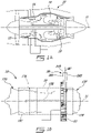
- Fig. 1A illustrates a gas turbine engine 10 of a type preferably provided for use in subsonic flight, generally comprising in serial flow communication a fan 12 through which ambient air is propelled, a compressor section 14 for pressurizing the air, a combustor 16 in which the compressed air is mixed with fuel and ignited for generating an annular stream of hot combustion gases, and a turbine section 18 for extracting energy from the combustion gases.
- Components of the gas turbine engine 10 rotate about a longitudinal center axis 11 of the gas turbine engine 10.
- Fig. 1B shows a gas turbine engine yoke 20.
- the gas turbine engine yoke 20 (sometimes referred to herein simply as “yoke 20") is a frame, harness or other suitable body used to support the gas turbine engine 10 and its components when the gas turbine engine 10 is being assembled and disassembled.
- the yoke 20 supports a first component of the gas turbine engine 10 during assembly or build of the gas turbine engine 10.
- the first component in the embodiment shown in Fig. 1B is an intermediate case 13 of the gas turbine engine 10.
- the intermediate case 13 is supported by the yoke 20, other components of the gas turbine engine 10 can be assembled to the intermediate case 13.
- a second component of the gas turbine engine 10 mounted to the intermediate case 13 is a core assembly 15 of the gas turbine engine 10.
- the core assembly 15 includes a high pressure compressor, a diffuser, and a high pressure turbine. After the core assembly 15 has been mounted to the intermediate case 13, other components of the gas turbine engine 10 can be assembled.
- MTF mid turbine frame
- LP low pressure
- LPT low pressure turbine
- TEC turbine exhaust case
- LPBOV low pressure bleed-off valve
- LPC low pressure compressor
- a build support 19 includes the yoke 20 and a stand 19A.
- the build support 19 is a structural assembly used to support components of the gas turbine engine 10 as it is being assembled and disassembled, and is thus an assembly/disassembly apparatus for the gas turbine engine 10.
- the stand 19A is a body or structure to which the yoke 20 is mounted.
- the stand 19A shown in Fig. 2A has a vertical orientation.
- the stand 19A is in the form of a vertical column in Fig. 2A which extends along an upright axis.
- the stand 19A rests on, and is supported by, a floor surface 19B, such as the internal floor surface of a manufacturing facility.
- the stand 19A is a support post.
- the stand 19A is fixed in place on the floor surface 19B.
- the stand 19A is displaceable along the floor surface 19B, such as by using wheels 19C. Displacing the stand 19A may facilitate storage, and free up floor space.
- the yoke 20 has a body 22 that forms the corpus of the yoke 20 and provides structure thereto.
- the body 22 includes an inner wall 24A spaced apart from an outer wall 24B, and first and second side walls 26A,26B which extend between the inner and outer walls 24A,24B.
- the inner wall 24A is the portion of the body 22 which is closest to the component of the gas turbine engine 10 supported by the yoke 20.
- the body 22 also defines a center line 21 of the yoke 20.
- the outer wall 24B is spaced outwardly from the inner wall 24A along a line being radial to the center line 21.
- the outer wall 24B is spaced radially outwardly from the inner wall 24A along a radial line from the center axis 11 of the gas turbine engine 10.
- the center line 21 and the center axis 11 are collinear.
- the first and second side walls 26A,26B are spaced apart from each other along a line parallel to the center line 21 of the yoke 20. The distance separating the first and second side walls 26A,26B defines the thickness of the yoke 20.
- One or both of the first and second side walls 26A,26B have recessed regions 26C which reduce the thickness of the yoke 20 at the recessed regions 26C, and which also reduce the overall weight of the yoke 20.
- the body 22 in the depicted embodiment is made from aluminum.
- the body 22 in an embodiment is made entirely from aluminum.
- the body 22 of the yoke 20 is arcuate. "Arcuate” indicates that at least some portion of the body 22 has a curvature.
- the inner and outer walls 24A,24B of the body 22 are curved along at least some of their length.
- the body 22 has a curved segment 22A extending between opposed ends, and straight segments 22B which each extend from one of the ends of the curved segment 22A.
- the curved segment 22A has a greater curvature than the straight segments 22B.
- the straight segments 22B in an embodiment have zero curvature.
- the straight segments 22B define the distal ends of the yoke 20, and are disposed on opposite ends of the curved segment 22A.
- the outer wall 24B has a greater radius, measured from the center line 21 of the yoke 20, than the radius of the inner wall 24A.
- the yoke 20 in Fig. 2A thus forms a "horseshoe" shape, and may surround more than roughly half of a circumference of the gas turbine engine 10.
- Other shapes for the yoke 20 are possible.
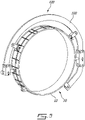
- Fig. 5 shows another yoke 120 whose body 122 surrounds roughly two-thirds of the circumference of the intermediate case 13 of the gas turbine engine 10.
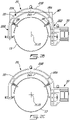
- the yoke 20 is rotatable between a horizontal orientation (see Fig. 2B ) and an upright orientation (see Fig. 2C ).
- the yoke 20 and its body 22 are rotatable with respect to the stand 19A.
- the first and second side walls 26A,26B have an upright or vertical orientation.
- the outer wall 24B is above the inner wall 24A.
- the center line 21 of the yoke 20 and the center axis 11 of the gas turbine engine 10 have a horizontal orientation and are parallel to the floor surface 19B.
- the first and second side walls 26A,26B have a horizontal orientation.
- the inner and outer walls 24A,24B have an upright or vertical orientation.
- the center line 21 of the yoke 20 and the center axis 11 of the gas turbine engine 10 have an upright or vertical orientation and are normal to the floor surface 19B.
- the yoke 20 is also rotatable to any orientation between the horizontal and upright orientations, and may to held in that orientation to support the gas turbine engine 10. Regardless of the orientation of the yoke 20, the inner wall 24A remains the portion of the body 22 which is closest to the component of the gas turbine engine 10 supported by the yoke 20.
- the body 22 of the yoke 20 defines a mounting plane MP, which is most easily visualized in Fig. 1B .
- the mounting plane MP shown from the side in Fig. 1B , extends through the inner and outer walls 24A,24B of the body 22.
- the mounting plane MP is also located between the first and second side walls 26A,26B. All of the yoke 20 lies in the mounting plane MP, such that the mounting plane MP extends through the curved segment 22A and the straight segments 22B of the body 22. This is shown visually in Figs. 1B , 2B and 3 , where portions of the mounting plane MP which are outside the body 22 are shown in solid lines, and where portions of the mounting plane MP within the body 22 are shown in dashed lines.
- the body 22 of the yoke 20 is parallel to the mounting plane MP.
- the mounting plane MP is normal to the center axis 11 of the gas turbine engine 10 irrespective of the orientation of the gas turbine engine 10.
- the mounting plane MP is transverse to the center line 21 of the yoke 20 irrespective of the orientation of the yoke 20.
- the mounting plane MP is normal to the center line 21 of the yoke 20 irrespective of the orientation of the yoke 20.
- the mounting plane MP is spaced from both the first and second side walls 26A,26B in a direction inwardly into the body 22 of the yoke 20.
- the mounting plane MP lies in the thickness of the body 22.
- the mounting plane MP is parallel to one or both of the first and second side walls 26A,26B.
- the mounting plane MP is normal to both the inner and outer walls 24A,24B of the body 22.
- the mounting plane MP is defined by one of the first and second side walls 26A,26B.
- the mounting plane MP is shown from the front in Fig. 2B .
- the yoke 20 has multiple engine attachments 28 which are attached to the yoke 20 and to the first component of the gas turbine engine 10, and thus help to mount the first component of the gas turbine engine 10 to the yoke 20, and help the yoke 20 to support the weight of the gas turbine engine 10 irrespective of its orientation.
- the engine attachments 28 therefore define points or positions at which the first component of the gas turbine engine 10 is joined to the yoke 20.
- the engine attachments 28 are spaced apart from each other along the inner wall 24A of the body 22.
- the engine attachments 28 are spaced apart from each other in a circumferential direction along the inner wall 24A of the body 22.
- the engine attachments 28 lie in the mounting plane MP. It will thus be appreciated that the first component of the gas turbine engine 10 is mounted to the yoke 20 along a single plane of attachment (i.e. the mounting plane MP). The points of attachment of the first component to the yoke 20 are within the mounting plane MP defined by the yoke 20. The points of attachment of the yoke 20 to the first component are all within the thickness of yoke 20. This allows the yoke 20 to grab the intermediate case 13, for example, at different points all in the same mounting plane MP.
- the engine attachments 28 seize the first component of the gas turbine engine 10 at the same locations on the first component where the aircraft supports the first component. The yoke 20 in such an embodiment is thus able to support the first component in the same plane as the aircraft does.
- the engine attachments 28 are shown as brackets.
- the brackets are selected at least in part based on the type of gas turbine engine 10 and/or its component to be supported by the yoke 20.
- Each of the engine attachments 28 have a first end 29A fixedly mounted to the inner wall 24A of the body 22, and a second end 29B fixedly mountable to the first component of the gas turbine engine 10, such as the horns of the intermediate case 13. It is understood by “fixedly mountable” and “fixedly mounted” that the engine attachments 28 prevent relative displacement or relative rotation between themselves and the objects to which they are attached. Therefore, the engine attachments 28 prevent a pivoting or rotating motion of the first component relative to the yoke 20.
- the engine attachments 28 are thus "anti-rotation" features, which may be helpful when rotating the yoke 20 and the gas turbine engine 10 between the horizontal and upright orientations.
- the first end 29A of each engine attachment is fixedly mounted to a flange 24A' extending inwardly toward the center line center line 21 of the yoke 20 from the inner wall 24A.
- the flanges 24A' have a mounting hole through which the first end 29A of the engine attachments 28 are secured.
- all of the engine attachments 28 are circumferentially spaced apart along the inner wall 24A of the curved segment 22A.
- the straight segments 22B are free of engine attachments 28.
- the engine attachments 28 extend between the first and second ends 29A,29B, and an entirety of the engine attachments 28 lie in the mounting plane MP, as shown in Fig. 3 .
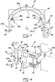
- the build support 19 also has an adapter 30 that is removably mountable to the yoke 20, and removably mounted to the stand 19A.
- the adapter 30 is thus positioned between the yoke 20 and the stand 19A. More particularly, the adapter 30 helps to suspend the yoke 20 from the stand 19A, and thus forms with the yoke 20 an assembly cantilevered from the stand 19A.
- the adapter 30 may be removed from both the yoke 20 and the stand 19A, and may also be secured thereto. The removability of the adapter 30 allows the build support 19 to be more easily disassembled, such that the yoke 20 and the stand 19A may be displaced to another location.
- the removability of the adapter 30 also helps with storage of the components of the build support 19.
- the adapter 30 allows another yoke 20, such as a second yoke 20 different from the one shown in the depicted embodiment, to be used with the same stand 19A.
- the adapter 30 thus allows the build support 19 to use multiple yokes 20 interchangeably. It will be appreciated that using the same adapter 30 with different types of yokes 20 allows the build support 19 to support different models of gas turbine engines 10.
- the adapter 30 is rotatable with the yoke 20 between the horizontal and upright orientations.
- the adapter 30 is rotatable with respect to the stand 19A.
- the adapter 30 has arm portions 32, each of which engage the first and second side walls 26A,26B of the body 22 of the yoke 20.
- the arm portions 32 are secured to the first and second side walls 26A,26B with any suitable fastener 33.
- the adapter 30 has a mounting portion 34 which is mounted to part of the stand 19A and secured thereto. In Fig. 4 , the mounting portion 34 is secured to a rotatable arm 19D of the stand 19A.
- the rotatable arm 19D defines an axis of rotation 27, about which the adapter 30 and the yoke 20 rotate between the horizontal and upright positions.
- the axis of rotation 27 of the adapter 30 and of the yoke 20 is defined by a bushing 35 in the rotatable arm 19D of the stand 19A.
- the adapter 30 in the depicted embodiment is made of aluminum.
- the adapter 30 may be mounted to a portable or displaceable stand 19A.
- trunnions 40 are used with the yoke 20 to further secure the gas turbine engine 10 to the yoke 20.
- the yoke 20 has holes 25 extending through the yoke 20 between the inner and outer walls 24A,24B.
- the holes 25 in Figs. 3 and 4 are located at the distal ends of the body 22.
- the holes 25 in Figs. 3 and 4 are present in only the straight segments 22B of the body 22.
- Each trunnion 40 is displaceable through one of the holes 25 to engage and support part of the first component of the gas turbine engine 10. In Figs.
- the trunnions 40 are displaceable along a line being radial to the center line 21 of the yoke 20. In Figs. 3 and 4 , the trunnions 40 are displaceable along a line being radial to the center axis 11 of the gas turbine engine 10. The trunnions 40 thus extend and retract to engage the first component, such as by engaging the intermediate case 13 in an appropriate location, such as a thrust bearing. The trunnions 40 are thus positioned along the yoke 20 to mimic how the gas turbine engine 10 is supported by the aircraft. The displaceability of the trunnions 40 allows for them to accommodate different engine sizes. In Figs.
- the adapter 30 has a recess 36 delimited by the arm portions 32.
- the trunnions 40 are displaceable into and out of the recess 36.
- the adapter 30 is thus designed to allow for the trunnion 40 to be fully retracted on one side of the yoke 20.
- the trunnions 40 may be secured in their position using any suitable technique, including for example with a pin 42.
- a method of assembling the gas turbine engine 10 includes mounting the first component of the gas turbine engine 10 to the yoke 20,120 along attachment points (e.g. the engine attachments 28) which lie in the single mounting plane MP defined by the yoke 20,120.
- the method includes rotating the yoke 20,120 to rotate the first component between the horizontal orientation and the upright orientation.
- the method also includes mounting another, second component of the gas turbine engine 10 to the first component.
- the method also applies mutatis mutandis to the disassembly of the gas turbine engine 10.
- mounting the first component includes mounting the intermediate case 13 to the yoke 20, 120
- mounting the second component includes mounting the core assembly 15 to the intermediate case 13.
- other components of the gas turbine engine 10 can be assembled, such as the mid turbine frame (MTF) module 17A, the low pressure (LP) shaft assembly 17B, the low pressure turbine (LPT) module 17C, the turbine exhaust case (TEC) 17D, the low pressure bleed-off valve (LPBOV) module 17E, and the low pressure compressor (LPC) module 17F.
- Core externals may also be installed.
- the process of assembling the gas turbine engine 10 begins by installing the intermediate case 13 into the yoke 20,120, and then mating the core assembly 15 to the intermediate case 13. If the yoke 20,120, and thus the intermediate case 13, are in the horizontal orientation, the core assembly 15 may be mated to the intermediate case 13 using a chain lift or ground-based tooling. If the yoke 20,120, and thus the intermediate case 13, are in the upright orientation, the core assembly 15 may be mated to the intermediate case 13 using a chain lift or ground-based tooling. If the core assembly 15 is installed vertically without the MTF module 17A, the MTF module 17A may then be installed while the gas turbine engine 10 remains in the upright orientation, via the chain lift.
- the gas turbine engine 10 may be rotated to the horizontal orientation, and the build can continue, such as by installing the LP Shaft assembly 17B, the LPT module 17C, the LPBOV module 17E, and the TEC 17D.
- the core assembly 15 can be mated to the intermediate case 13 using a core cart.
- the build support 19 and its yoke 20 disclosed herein allow for assembly/disassembly of the gas turbine engine 10 without being completely reliant on an immobile carrier, while using existing infrastructure such as the stand 19A.
- the build support 19 helps to reduce the utilization of expensive carrier infrastructure to progress the build of the gas turbine engine 10 past the MTF module 17A mating with the core assembly 15.
Landscapes
- Engineering & Computer Science (AREA)
- Mechanical Engineering (AREA)
- General Engineering & Computer Science (AREA)
- Turbine Rotor Nozzle Sealing (AREA)
- Structures Of Non-Positive Displacement Pumps (AREA)
Claims (13)
- Bauträger (19) für einen Gasturbinenmotor (10), umfassend:einen Ständer (19A);ein Joch (20), das einen bogenförmigen Körper (22) umfasst, der an einem Ständer (19A) montierbar ist, dadurch gekennzeichnet, dass:das Joch (20) zwischen einer aufrechten Ausrichtung und einer horizontalen Ausrichtung drehbar ist, wobei der bogenförmige Körper (22) eine von einer Außenwand (24B) beabstandete Innenwand (24A) und sich erstreckende erste und zweite Seitenwände (26A, 26B) zwischen der Innen- und der Außenwand (24A, 24B) aufweist, sich eine Montageebene des Jochs (20) durch die Innen- und die Außenwand (24A, 24B) erstreckt und zwischen der ersten und der zweiten Seitenwand (26A, 26B) positioniert ist und Motorbefestigungen (28) entlang der Innenwand (24A) beabstandet sind und in der Montageebene liegen; undder Bauträger (19) ferner einen Adapter (30) umfasst, der abnehmbar an dem Joch (20) montierbar ist und abnehmbar an dem Ständer (19A) montierbar ist, um das Joch (20) an dem Ständer (19A) zu montieren, wobei der Adapter (30) zwischen der aufrechten Ausrichtung und der horizontalen Ausrichtung drehbar ist, um dadurch das Joch (20) zwischen der aufrechten Ausrichtung und der horizontalen Ausrichtung zu drehen.
- Bauträger (19) nach Anspruch 1, wobei die Montageebene parallel zu einer oder beiden der ersten und der zweiten Seitenwand (26A, 26B) ist.
- Bauträger (19) nach Anspruch 1 oder 2, wobei der Körper (22) Löcher (25) aufweist, die sich durch den Körper (22) zwischen der Innen- und der Außenwand (24A, 24B) erstrecken, wobei das Joch (20) Zapfen (40) aufweist, die durch die Löcher (25) verschiebbar sind, um mit einem Gasturbinenmotor (10) in Eingriff zu treten.
- Bauträger (19) nach einem der Ansprüche 1 bis 3, wobei die Motorbefestigungen (28) ein erstes Ende (29A), das fest an der Innenwand (24A) montiert ist, und ein zweites Ende (29B) aufweisen, das fest an dem Gasturbinenmotor (10) montierbar ist, wobei sich die Motorbefestigungen (28) zwischen dem ersten und dem zweiten Ende (29A, 29B) erstrecken und eine Gesamtheit der Motorbefestigungen (28) in der Montageebene liegen.
- Bauträger (19) nach einem der vorhergehenden Ansprüche, wobei der Körper (22) ein gekrümmtes Segment (22A), das sich zwischen seinen Enden erstreckt, und gerade Segmente (22B) aufweist, die sich jeweils von einem der Enden des gekrümmten Segments (22A) erstrecken.
- Bauträger (19) nach Anspruch 5, wobei die Motorbefestigungen (28) entlang der Innenwand (24A) des gekrümmten Segments (22A) beabstandet sind.
- Bauträger (19) nach einem der vorhergehenden Ansprüche, umfassend ein zweites Joch (20), das sich von dem Joch (20) unterscheidet, wobei der Adapter (30) separat an jedem von dem zweiten Joch (20) und dem Joch (20) montierbar ist.
- Bauträger (19) nach einem der vorhergehenden Ansprüche, wobei der Ständer (19A) entlang einer Bodenoberfläche verschiebbar ist.
- Verfahren zum Zusammenbauen eines Gasturbinenmotors (10), umfassend:Montieren einer ersten Komponente des Gasturbinenmotors (10) an einem Joch (20) entlang Befestigungspunkten, die in einer einzigen Montageebene (MP) liegen, die durch das Joch (20) definiert ist;Drehen des Jochs (20), um die erste Komponente zwischen einer horizontalen Ausrichtung und einer aufrechten Ausrichtung zu drehen; undMontieren einer zweiten Komponente des Gasturbinenmotors (10) an der ersten Komponente.
- Verfahren nach Anspruch 9, wobei das Montieren der ersten Komponente das Montieren eines Zwischengehäuses (13) des Gasturbinenmotors (10) an dem Joch (20) umfasst und das Montieren der zweiten Komponente das Montieren einer Kernanordnung (15) des Gasturbinenmotors (10) an der ersten Komponente umfasst, wobei die Kernanordnung (15) einen Hochdruckkompressor, einen Diffusor und eine Hochdruckturbine umfasst.
- Verfahren nach Anspruch 9 oder 10, wobei das Montieren der ersten Komponente das Sichern der ersten Komponente an den Befestigungspunkten an umlaufend beabstandeten Stellen an dem Joch (20) umfasst.
- Verfahren nach einem der Ansprüche 9 bis 11, wobei das Montieren der ersten Komponente das Ineingriffbringen der ersten Komponente mit Zapfen (40) umfasst, die durch das Joch (20) verschiebbar sind.
- Verfahren nach einem der Ansprüche 9 bis 12, umfassend das Montieren des Jochs (20) an einem verschiebbaren Ständer (19A) und das Verschieben des Jochs (20) und der daran montierten ersten Komponente entlang einer Bodenoberfläche (19B).
Applications Claiming Priority (1)
| Application Number | Priority Date | Filing Date | Title |
|---|---|---|---|
| US16/398,824 US11248497B2 (en) | 2019-04-30 | 2019-04-30 | Gas turbine engine yoke and build support |
Publications (2)
| Publication Number | Publication Date |
|---|---|
| EP3734026A1 EP3734026A1 (de) | 2020-11-04 |
| EP3734026B1 true EP3734026B1 (de) | 2022-06-01 |
Family
ID=70482467
Family Applications (1)
| Application Number | Title | Priority Date | Filing Date |
|---|---|---|---|
| EP20172547.0A Active EP3734026B1 (de) | 2019-04-30 | 2020-04-30 | Gasturbinenmotorjoch und bauträger |
Country Status (3)
| Country | Link |
|---|---|
| US (1) | US11248497B2 (de) |
| EP (1) | EP3734026B1 (de) |
| CA (1) | CA3080345A1 (de) |
Cited By (1)
| Publication number | Priority date | Publication date | Assignee | Title |
|---|---|---|---|---|
| EP4656527A1 (de) * | 2024-05-30 | 2025-12-03 | Pratt & Whitney Canada Corp. | Stützständeranordnung für flugzeugtriebwerk |
Families Citing this family (7)
| Publication number | Priority date | Publication date | Assignee | Title |
|---|---|---|---|---|
| FR3076236B1 (fr) * | 2017-12-28 | 2019-12-06 | Safran Aircraft Engines | Outil de demontage d'une piece annulaire de turbomachine, procede de demontage et de reassemblage associes |
| FR3090588B1 (fr) * | 2018-12-21 | 2021-01-22 | Safran Aircraft Engines | Outillage pour placer un ensemble propulsif d’une position horizontale a une position verticale |
| US11686221B2 (en) | 2021-12-01 | 2023-06-27 | Pratt & Whitney Canada Corp. | Aircraft engine repair tool and method for removal and installation of a mid turbine frame in an aircraft engine |
| DE102024116524A1 (de) * | 2024-06-12 | 2025-12-18 | Broetje-Automation Gmbh | Verfahren zur Aufnahme einer Turbine |
| US20260001660A1 (en) * | 2024-06-28 | 2026-01-01 | Pratt & Whitney Canada Corp. | Aircraft engine assembly stand |
| US20260015952A1 (en) * | 2024-07-15 | 2026-01-15 | Ge Infrastructure Technology Llc | Inner compressor case suspension device and method of alignment |
| US20260021896A1 (en) * | 2024-07-22 | 2026-01-22 | Pratt & Whitney Canada Corp. | Aircraft engine assembly stand and method of using the same |
Family Cites Families (12)
| Publication number | Priority date | Publication date | Assignee | Title |
|---|---|---|---|---|
| US2586263A (en) | 1944-10-12 | 1952-02-19 | Webb Co Jervis B | Conveyer |
| US2703252A (en) | 1952-04-02 | 1955-03-01 | Rohr Aircraft Corp | Multiple tilting arc support |
| US2825477A (en) | 1953-09-04 | 1958-03-04 | Henry M Ross | Engine work stand and method of using the same |
| US3085798A (en) | 1959-02-19 | 1963-04-16 | Lockheed Aircraft Corp | Multi-purpose powerplant stand |
| US4010942A (en) | 1974-03-04 | 1977-03-08 | Gary Lee Ward | Repair support assembly for automotive transmissions |
| DE2719850C3 (de) | 1977-05-04 | 1981-06-25 | MTU Motoren- und Turbinen-Union München GmbH, 8000 München | Vorrichtung zur Wartung von Gasturbinentriebwerken, insbesondere Gasturbinenstrahltriebwerken |
| JP2877296B2 (ja) | 1995-09-11 | 1999-03-31 | 三菱重工業株式会社 | ガスタービン燃焼器の取付、取外し装置 |
| FR2952922B1 (fr) * | 2009-11-20 | 2012-05-25 | Snecma | Ensemble de manutention d'un module de moteur d'aeronef |
| US9228451B2 (en) | 2011-05-03 | 2016-01-05 | Pratt & Whitney Canada Corp. | Gas turbine engine module adapter to a carrier |
| JP5806310B2 (ja) * | 2011-06-23 | 2015-11-10 | 平田機工株式会社 | ワーク支持装置 |
| FR3043000B1 (fr) | 2015-10-29 | 2018-04-13 | Safran Aircraft Engines | Portique d'assemblage de moteur |
| FR3058987B1 (fr) * | 2016-11-24 | 2019-08-02 | Safran Aircraft Engines | Organe et chariot pour la depose, le transport, et la maintenance, d'une turbomachine |
-
2019
- 2019-04-30 US US16/398,824 patent/US11248497B2/en active Active
-
2020
- 2020-04-28 CA CA3080345A patent/CA3080345A1/en active Pending
- 2020-04-30 EP EP20172547.0A patent/EP3734026B1/de active Active
Cited By (1)
| Publication number | Priority date | Publication date | Assignee | Title |
|---|---|---|---|---|
| EP4656527A1 (de) * | 2024-05-30 | 2025-12-03 | Pratt & Whitney Canada Corp. | Stützständeranordnung für flugzeugtriebwerk |
Also Published As
| Publication number | Publication date |
|---|---|
| EP3734026A1 (de) | 2020-11-04 |
| CA3080345A1 (en) | 2020-10-30 |
| US20200347752A1 (en) | 2020-11-05 |
| US11248497B2 (en) | 2022-02-15 |
Similar Documents
| Publication | Publication Date | Title |
|---|---|---|
| EP3734026B1 (de) | Gasturbinenmotorjoch und bauträger | |
| US10808622B2 (en) | Turbine engine case mount and dismount | |
| US10329956B2 (en) | Multi-function boss for a turbine exhaust case | |
| US10458282B2 (en) | Gas turbine engine module adapter to a carrier | |
| EP2855881B1 (de) | Gondelgabelung für einem gasturbinenmotor | |
| EP2938847B1 (de) | Installationshalterung für ein turbinenabgasgehäuse | |
| US9212607B2 (en) | Intermediate structure for independently de-mountable propulsion components | |
| US9266202B2 (en) | Rotor centralization for turbine engine assembly | |
| US20230366325A1 (en) | Turbomachine module provided with a propeller and offset stator vanes | |
| US20130233997A1 (en) | Turbine engine case mount | |
| KR102191182B1 (ko) | 로터 블록을 설치 및 분리하기 위한 캔틸레버 슬라이드 | |
| EP3421408B1 (de) | Handhabungsanordnung für eine turbomaschinenkomponente | |
| US9709276B2 (en) | Method and tool for installation of a transition duct | |
| EP2938862B1 (de) | Mehrzweckhalterung | |
| CN113356949B (zh) | 一种用于航空发动机机匣间的固定支撑装置 | |
| CN114394533B (zh) | 燃气轮机进气缸检修转运系统和检修转运方法 | |
| CN110494256B (zh) | 用于安装和/或拆卸的方法、应用于该方法的设备、燃烧器适配器、过渡部适配器、装置以及机器人的应用 | |
| US12473845B2 (en) | System and method for applying trim balance to a module of the gas turbine engine | |
| US20260021896A1 (en) | Aircraft engine assembly stand and method of using the same | |
| US11927107B2 (en) | Tool and method for disassembling and moving a TRV-type turbine casing of an aircraft turbine engine | |
| JP2025174203A (ja) | 排気車室の分解組立方法、及び軸受台下半の支持装置 |
Legal Events
| Date | Code | Title | Description |
|---|---|---|---|
| PUAI | Public reference made under article 153(3) epc to a published international application that has entered the european phase |
Free format text: ORIGINAL CODE: 0009012 |
|
| STAA | Information on the status of an ep patent application or granted ep patent |
Free format text: STATUS: THE APPLICATION HAS BEEN PUBLISHED |
|
| AK | Designated contracting states |
Kind code of ref document: A1 Designated state(s): AL AT BE BG CH CY CZ DE DK EE ES FI FR GB GR HR HU IE IS IT LI LT LU LV MC MK MT NL NO PL PT RO RS SE SI SK SM TR |
|
| AX | Request for extension of the european patent |
Extension state: BA ME |
|
| STAA | Information on the status of an ep patent application or granted ep patent |
Free format text: STATUS: REQUEST FOR EXAMINATION WAS MADE |
|
| 17P | Request for examination filed |
Effective date: 20210504 |
|
| RBV | Designated contracting states (corrected) |
Designated state(s): AL AT BE BG CH CY CZ DE DK EE ES FI FR GB GR HR HU IE IS IT LI LT LU LV MC MK MT NL NO PL PT RO RS SE SI SK SM TR |
|
| GRAP | Despatch of communication of intention to grant a patent |
Free format text: ORIGINAL CODE: EPIDOSNIGR1 |
|
| STAA | Information on the status of an ep patent application or granted ep patent |
Free format text: STATUS: GRANT OF PATENT IS INTENDED |
|
| INTG | Intention to grant announced |
Effective date: 20211222 |
|
| GRAS | Grant fee paid |
Free format text: ORIGINAL CODE: EPIDOSNIGR3 |
|
| GRAA | (expected) grant |
Free format text: ORIGINAL CODE: 0009210 |
|
| STAA | Information on the status of an ep patent application or granted ep patent |
Free format text: STATUS: THE PATENT HAS BEEN GRANTED |
|
| AK | Designated contracting states |
Kind code of ref document: B1 Designated state(s): AL AT BE BG CH CY CZ DE DK EE ES FI FR GB GR HR HU IE IS IT LI LT LU LV MC MK MT NL NO PL PT RO RS SE SI SK SM TR |
|
| REG | Reference to a national code |
Ref country code: GB Ref legal event code: FG4D |
|
| REG | Reference to a national code |
Ref country code: AT Ref legal event code: REF Ref document number: 1495496 Country of ref document: AT Kind code of ref document: T Effective date: 20220615 Ref country code: CH Ref legal event code: EP Ref country code: DE Ref legal event code: R096 Ref document number: 602020003337 Country of ref document: DE |
|
| REG | Reference to a national code |
Ref country code: IE Ref legal event code: FG4D |
|
| REG | Reference to a national code |
Ref country code: LT Ref legal event code: MG9D |
|
| REG | Reference to a national code |
Ref country code: NL Ref legal event code: MP Effective date: 20220601 |
|
| PG25 | Lapsed in a contracting state [announced via postgrant information from national office to epo] |
Ref country code: SE Free format text: LAPSE BECAUSE OF FAILURE TO SUBMIT A TRANSLATION OF THE DESCRIPTION OR TO PAY THE FEE WITHIN THE PRESCRIBED TIME-LIMIT Effective date: 20220601 Ref country code: NO Free format text: LAPSE BECAUSE OF FAILURE TO SUBMIT A TRANSLATION OF THE DESCRIPTION OR TO PAY THE FEE WITHIN THE PRESCRIBED TIME-LIMIT Effective date: 20220901 Ref country code: LT Free format text: LAPSE BECAUSE OF FAILURE TO SUBMIT A TRANSLATION OF THE DESCRIPTION OR TO PAY THE FEE WITHIN THE PRESCRIBED TIME-LIMIT Effective date: 20220601 Ref country code: HR Free format text: LAPSE BECAUSE OF FAILURE TO SUBMIT A TRANSLATION OF THE DESCRIPTION OR TO PAY THE FEE WITHIN THE PRESCRIBED TIME-LIMIT Effective date: 20220601 Ref country code: GR Free format text: LAPSE BECAUSE OF FAILURE TO SUBMIT A TRANSLATION OF THE DESCRIPTION OR TO PAY THE FEE WITHIN THE PRESCRIBED TIME-LIMIT Effective date: 20220902 Ref country code: FI Free format text: LAPSE BECAUSE OF FAILURE TO SUBMIT A TRANSLATION OF THE DESCRIPTION OR TO PAY THE FEE WITHIN THE PRESCRIBED TIME-LIMIT Effective date: 20220601 Ref country code: BG Free format text: LAPSE BECAUSE OF FAILURE TO SUBMIT A TRANSLATION OF THE DESCRIPTION OR TO PAY THE FEE WITHIN THE PRESCRIBED TIME-LIMIT Effective date: 20220901 |
|
| REG | Reference to a national code |
Ref country code: AT Ref legal event code: MK05 Ref document number: 1495496 Country of ref document: AT Kind code of ref document: T Effective date: 20220601 |
|
| PG25 | Lapsed in a contracting state [announced via postgrant information from national office to epo] |
Ref country code: RS Free format text: LAPSE BECAUSE OF FAILURE TO SUBMIT A TRANSLATION OF THE DESCRIPTION OR TO PAY THE FEE WITHIN THE PRESCRIBED TIME-LIMIT Effective date: 20220601 Ref country code: PL Free format text: LAPSE BECAUSE OF FAILURE TO SUBMIT A TRANSLATION OF THE DESCRIPTION OR TO PAY THE FEE WITHIN THE PRESCRIBED TIME-LIMIT Effective date: 20220601 Ref country code: LV Free format text: LAPSE BECAUSE OF FAILURE TO SUBMIT A TRANSLATION OF THE DESCRIPTION OR TO PAY THE FEE WITHIN THE PRESCRIBED TIME-LIMIT Effective date: 20220601 |
|
| PG25 | Lapsed in a contracting state [announced via postgrant information from national office to epo] |
Ref country code: NL Free format text: LAPSE BECAUSE OF FAILURE TO SUBMIT A TRANSLATION OF THE DESCRIPTION OR TO PAY THE FEE WITHIN THE PRESCRIBED TIME-LIMIT Effective date: 20220601 |
|
| PG25 | Lapsed in a contracting state [announced via postgrant information from national office to epo] |
Ref country code: SM Free format text: LAPSE BECAUSE OF FAILURE TO SUBMIT A TRANSLATION OF THE DESCRIPTION OR TO PAY THE FEE WITHIN THE PRESCRIBED TIME-LIMIT Effective date: 20220601 Ref country code: SK Free format text: LAPSE BECAUSE OF FAILURE TO SUBMIT A TRANSLATION OF THE DESCRIPTION OR TO PAY THE FEE WITHIN THE PRESCRIBED TIME-LIMIT Effective date: 20220601 Ref country code: RO Free format text: LAPSE BECAUSE OF FAILURE TO SUBMIT A TRANSLATION OF THE DESCRIPTION OR TO PAY THE FEE WITHIN THE PRESCRIBED TIME-LIMIT Effective date: 20220601 Ref country code: PT Free format text: LAPSE BECAUSE OF FAILURE TO SUBMIT A TRANSLATION OF THE DESCRIPTION OR TO PAY THE FEE WITHIN THE PRESCRIBED TIME-LIMIT Effective date: 20221003 Ref country code: ES Free format text: LAPSE BECAUSE OF FAILURE TO SUBMIT A TRANSLATION OF THE DESCRIPTION OR TO PAY THE FEE WITHIN THE PRESCRIBED TIME-LIMIT Effective date: 20220601 Ref country code: EE Free format text: LAPSE BECAUSE OF FAILURE TO SUBMIT A TRANSLATION OF THE DESCRIPTION OR TO PAY THE FEE WITHIN THE PRESCRIBED TIME-LIMIT Effective date: 20220601 Ref country code: CZ Free format text: LAPSE BECAUSE OF FAILURE TO SUBMIT A TRANSLATION OF THE DESCRIPTION OR TO PAY THE FEE WITHIN THE PRESCRIBED TIME-LIMIT Effective date: 20220601 Ref country code: AT Free format text: LAPSE BECAUSE OF FAILURE TO SUBMIT A TRANSLATION OF THE DESCRIPTION OR TO PAY THE FEE WITHIN THE PRESCRIBED TIME-LIMIT Effective date: 20220601 |
|
| PG25 | Lapsed in a contracting state [announced via postgrant information from national office to epo] |
Ref country code: IS Free format text: LAPSE BECAUSE OF FAILURE TO SUBMIT A TRANSLATION OF THE DESCRIPTION OR TO PAY THE FEE WITHIN THE PRESCRIBED TIME-LIMIT Effective date: 20221001 |
|
| REG | Reference to a national code |
Ref country code: DE Ref legal event code: R097 Ref document number: 602020003337 Country of ref document: DE |
|
| PG25 | Lapsed in a contracting state [announced via postgrant information from national office to epo] |
Ref country code: AL Free format text: LAPSE BECAUSE OF FAILURE TO SUBMIT A TRANSLATION OF THE DESCRIPTION OR TO PAY THE FEE WITHIN THE PRESCRIBED TIME-LIMIT Effective date: 20220601 |
|
| PLBE | No opposition filed within time limit |
Free format text: ORIGINAL CODE: 0009261 |
|
| STAA | Information on the status of an ep patent application or granted ep patent |
Free format text: STATUS: NO OPPOSITION FILED WITHIN TIME LIMIT |
|
| PG25 | Lapsed in a contracting state [announced via postgrant information from national office to epo] |
Ref country code: DK Free format text: LAPSE BECAUSE OF FAILURE TO SUBMIT A TRANSLATION OF THE DESCRIPTION OR TO PAY THE FEE WITHIN THE PRESCRIBED TIME-LIMIT Effective date: 20220601 |
|
| 26N | No opposition filed |
Effective date: 20230302 |
|
| PG25 | Lapsed in a contracting state [announced via postgrant information from national office to epo] |
Ref country code: SI Free format text: LAPSE BECAUSE OF FAILURE TO SUBMIT A TRANSLATION OF THE DESCRIPTION OR TO PAY THE FEE WITHIN THE PRESCRIBED TIME-LIMIT Effective date: 20220601 |
|
| P01 | Opt-out of the competence of the unified patent court (upc) registered |
Effective date: 20230530 |
|
| REG | Reference to a national code |
Ref country code: CH Ref legal event code: PL |
|
| PG25 | Lapsed in a contracting state [announced via postgrant information from national office to epo] |
Ref country code: LU Free format text: LAPSE BECAUSE OF NON-PAYMENT OF DUE FEES Effective date: 20230430 |
|
| REG | Reference to a national code |
Ref country code: BE Ref legal event code: MM Effective date: 20230430 |
|
| PG25 | Lapsed in a contracting state [announced via postgrant information from national office to epo] |
Ref country code: MC Free format text: LAPSE BECAUSE OF FAILURE TO SUBMIT A TRANSLATION OF THE DESCRIPTION OR TO PAY THE FEE WITHIN THE PRESCRIBED TIME-LIMIT Effective date: 20220601 |
|
| PG25 | Lapsed in a contracting state [announced via postgrant information from national office to epo] |
Ref country code: MC Free format text: LAPSE BECAUSE OF FAILURE TO SUBMIT A TRANSLATION OF THE DESCRIPTION OR TO PAY THE FEE WITHIN THE PRESCRIBED TIME-LIMIT Effective date: 20220601 Ref country code: LI Free format text: LAPSE BECAUSE OF NON-PAYMENT OF DUE FEES Effective date: 20230430 Ref country code: IT Free format text: LAPSE BECAUSE OF FAILURE TO SUBMIT A TRANSLATION OF THE DESCRIPTION OR TO PAY THE FEE WITHIN THE PRESCRIBED TIME-LIMIT Effective date: 20220601 Ref country code: CH Free format text: LAPSE BECAUSE OF NON-PAYMENT OF DUE FEES Effective date: 20230430 |
|
| REG | Reference to a national code |
Ref country code: IE Ref legal event code: MM4A |
|
| PG25 | Lapsed in a contracting state [announced via postgrant information from national office to epo] |
Ref country code: BE Free format text: LAPSE BECAUSE OF NON-PAYMENT OF DUE FEES Effective date: 20230430 |
|
| PG25 | Lapsed in a contracting state [announced via postgrant information from national office to epo] |
Ref country code: IE Free format text: LAPSE BECAUSE OF NON-PAYMENT OF DUE FEES Effective date: 20230430 |
|
| PG25 | Lapsed in a contracting state [announced via postgrant information from national office to epo] |
Ref country code: IE Free format text: LAPSE BECAUSE OF NON-PAYMENT OF DUE FEES Effective date: 20230430 |
|
| PG25 | Lapsed in a contracting state [announced via postgrant information from national office to epo] |
Ref country code: BG Free format text: LAPSE BECAUSE OF FAILURE TO SUBMIT A TRANSLATION OF THE DESCRIPTION OR TO PAY THE FEE WITHIN THE PRESCRIBED TIME-LIMIT Effective date: 20220601 |
|
| PG25 | Lapsed in a contracting state [announced via postgrant information from national office to epo] |
Ref country code: BG Free format text: LAPSE BECAUSE OF FAILURE TO SUBMIT A TRANSLATION OF THE DESCRIPTION OR TO PAY THE FEE WITHIN THE PRESCRIBED TIME-LIMIT Effective date: 20220601 |
|
| PGFP | Annual fee paid to national office [announced via postgrant information from national office to epo] |
Ref country code: DE Payment date: 20250319 Year of fee payment: 6 |
|
| PG25 | Lapsed in a contracting state [announced via postgrant information from national office to epo] |
Ref country code: CY Free format text: LAPSE BECAUSE OF FAILURE TO SUBMIT A TRANSLATION OF THE DESCRIPTION OR TO PAY THE FEE WITHIN THE PRESCRIBED TIME-LIMIT; INVALID AB INITIO Effective date: 20200430 |
|
| PG25 | Lapsed in a contracting state [announced via postgrant information from national office to epo] |
Ref country code: HU Free format text: LAPSE BECAUSE OF FAILURE TO SUBMIT A TRANSLATION OF THE DESCRIPTION OR TO PAY THE FEE WITHIN THE PRESCRIBED TIME-LIMIT; INVALID AB INITIO Effective date: 20200430 |
|
| PG25 | Lapsed in a contracting state [announced via postgrant information from national office to epo] |
Ref country code: TR Free format text: LAPSE BECAUSE OF FAILURE TO SUBMIT A TRANSLATION OF THE DESCRIPTION OR TO PAY THE FEE WITHIN THE PRESCRIBED TIME-LIMIT Effective date: 20220601 |
|
| PGFP | Annual fee paid to national office [announced via postgrant information from national office to epo] |
Ref country code: GB Payment date: 20260319 Year of fee payment: 7 |
|
| PGFP | Annual fee paid to national office [announced via postgrant information from national office to epo] |
Ref country code: FR Payment date: 20260320 Year of fee payment: 7 |