EP3733587B1 - Vorrichtung und verfahren zum abdichten eines flaschenhalses - Google Patents
Vorrichtung und verfahren zum abdichten eines flaschenhalses Download PDFInfo
- Publication number
- EP3733587B1 EP3733587B1 EP20167976.8A EP20167976A EP3733587B1 EP 3733587 B1 EP3733587 B1 EP 3733587B1 EP 20167976 A EP20167976 A EP 20167976A EP 3733587 B1 EP3733587 B1 EP 3733587B1
- Authority
- EP
- European Patent Office
- Prior art keywords
- bottle
- bottles
- neck
- rotation
- sealing material
- Prior art date
- Legal status (The legal status is an assumption and is not a legal conclusion. Google has not performed a legal analysis and makes no representation as to the accuracy of the status listed.)
- Active
Links
Images


Classifications
-
- B—PERFORMING OPERATIONS; TRANSPORTING
- B67—OPENING, CLOSING OR CLEANING BOTTLES, JARS OR SIMILAR CONTAINERS; LIQUID HANDLING
- B67B—APPLYING CLOSURE MEMBERS TO BOTTLES JARS, OR SIMILAR CONTAINERS; OPENING CLOSED CONTAINERS
- B67B5/00—Applying protective or decorative covers to closures; Devices for securing bottle closures with wire
- B67B5/03—Applying protective or decorative covers to closures, e.g. by forming in situ
- B67B5/05—Applying protective or decorative covers to closures, e.g. by forming in situ by applying liquids, e.g. by dipping
Definitions
- the present invention relates to a machine and a method for sealing the mouth of at least one bottle by creating a capsule of sealing material around the neck of the bottle.
- sealing the mouth of the bottle with a sealing material, for example sealing wax or shellac, so as to ensure the final buyer on the integrity of the package.
- a sealing material for example sealing wax or shellac
- a closure cap of the bottles or containers is first applied, and then the bottles or containers are sealed at the top with a sealing material such as sealing wax or shellac.
- a sealing material such as sealing wax or shellac.
- the application of the seal can be performed manually immersing the terminal part the bottle neck in a sealing wax or shellac bath in a special tank.
- the tank is preferably equipped with heating means to maintain the sealing wax or shellac in a liquid or semi-liquid state.
- the neck of the bottle is therefore kept immersed for long enough to ensure the adhesion of the sealing wax or shellac to the neck and the bottle is therefore removed from the tank.
- Machines for the automatic sealing of bottles are currently known, which are provided with a mobile support in which one or more bottles or containers to be sealed can be stored.
- the mobile support can immerse the terminal part of the neck of the bottles or containers in a tank containing wax or shellac in a molten, liquid or semi-liquid state, placed under the mobile support, rotate each bottle or container around its own longitudinal axis, keep the neck immersed and in rotation for long enough to ensure the application of the wax and, interrupting the rotation of each bottle, to extract the bottles or containers from the tank.
- the dripping step may not be sufficient to obtain a capsule with a high homogeneity, such that even at a possible subsequent stamping of the head surface the said drop of material excess not yet solidified is not generated.
- the molten material tends to flow from the entire capsule towards the drop formation zone, in proximity of a point on the peripheral edge of the capsule head surface.
- an accumulation of material remains in the drop formation area, which can then run down the neck forming the said drop of excess material which has not yet solidified.
- US 2.081.478 A describes a rotary machine in which the bottles are first immersed in a shellac bath by means of a cam, then they are lifted and then placed again to drip in an arched drip tray, while rotating around the column of the machine. Also in this case, when each bottle is brought back from the dripping position to the final position, an accumulation of material remains in the drop formation area, which can lead to the formation of a drop along the neck.
- the present invention aims at solving this technical problem by means of a method in accordance with claim 1, which further comprises the following steps:
- first dripping position and the second dripping position alternatively identify two diametrically opposite points of the end edge of the bottle neck as the lower extreme point of the bottle.
- dripping is performed in two consecutive phases in which the bottle is inclined in opposite directions with respect to a vertical plane.
- the sealing material tends to accumulate in a first drop formation point on the peripheral edge of the head surface, while when the bottle is brought to the second dripping position this accumulation takes place in a second drop formation point on the peripheral edge of the head surface, in particular in an area diametrically opposite to the first drop formation point.
- the accumulation of sealing material of the first dripping position is thus redistributed in a more uniform way in the capsule just formed, in particular in the head surface thereof.
- the capsule material is homogeneously distributed, avoiding local accumulations and consequent formation of drops along the neck.
- the bottle is initially gripped in the initial position and finally released in the final position, in which initial position and final position the bottle is erected with the neck facing upwards.
- the inclination of the longitudinal axis of the bottle with respect to said vertical plane is comprised between 20° and 80°.
- the inclination of the longitudinal axis of the bottle with respect to said vertical plane is comprised between 5° and 45°.
- Object of the present invention is also a machine according to claim 6 for sealing the mouth of at least one bottle by creating a capsule of sealing material around at least the neck of the bottle.
- the machine comprises a base, a tank for a sealing material in the molten state, a head movably fixed to the base, which head is provided with means of rotation around a horizontal axis and means of translation along a vertical axis and is provided with of gripping means for one or more bottles.
- the machine also comprises a control unit for the rotation means and the translation means of said head. The control unit is configured to operate the rotation means and the translation means of said head so as to perform the method described above.
- control unit comprises processing means configured for the execution of a logical program to activate the head.
- control unit is configured to initially activate a rotation or rototranslation of the bottle around a horizontal axis from an initial position to an immersion position, in which immersion position the bottle has the neck facing downwards and immersed at least partially in a bath of said sealing material in the molten state.
- control unit activates the head to rotate or rototranslate the bottle to a first dripping position, in which first dripping position the bottle is completely extracted from the sealing material bath and has the neck facing downwards and has its own longitudinal axis inclined with respect to a vertical plane.
- control unit activates the head to make a rotation or rototranslation of the bottle in a second dripping position, in which second dripping position the bottle is completely extracted from the bath of sealing material and has the neck facing downwards and has its own longitudinal axis inclined with respect to said vertical plane in opposite direction compared to said first dripping position.
- control unit operates the head to rotate or rototranslate the bottle to a final position.
- the gripping means are configured to grasp a plurality of bottles arranged side by side.
- an area for picking and releasing the bottles by the gripping means is provided, a conveyor belt being provided for the delivery of the bottles in the pick-up and drop area and for the removal of the bottles from the pick-up and drop zone.
- the bottles are positioned side by side in the picking up and release area by means of a conveyor belt on which the bottles lie resting in an upright condition.
- the belt places a predetermined number of bottles in the collection and release area, and subsequently removes them. This allows the automation of the sealing phase of the mouth of the bottles within a wider industrial line, for example by providing an automated station downstream of the machine for stamping the head surface of the formed capsules.
- the figures illustrate an executive example of the machine object of the present invention.
- the machine is adapted to seal the mouth of a plurality of bottles 2 by creating a capsule of sealing material around the neck 20 of the bottle 2.
- the machine is designed to act on a plurality of bottles, for example 8 or 12 or preferably 14 bottles.
- it is possible to provide even fewer bottles, even up to a single bottle.
- the machine comprises a base 10, only partially illustrated in the figures.
- the base 10 supports a tank 11 for a molten sealing material, such as wax or shellac.
- the tank 11 is of such a size as to contain a quantity of sealing material in the molten state sufficient to immerse at least the entire neck of the bottles 2.
- the tank 11 is provided with means for heating the sealing material to keep it in a molten condition, such as for example one or more electrical resistances arranged in the peripheral walls of the tank 11.
- the tank 11 is surrounded at least on two opposite sides by inclined slides 110 for the recovery of the sealing material dripped outside the tank 11 and for its funnelling back inside the tank 11.
- the slides 110 are at least partially heated, so as to avoid hardening and resulting accumulation of the sealing material on the slides 110 themselves.
- the machine also comprises a head 3 movably fixed to the base 10 and provided with means of translation along a vertical axis and means for rotation around a horizontal axis and provided with means for gripping the bottles 2.
- the translation means of the head 3 comprise a translation section 30 preferably constituted by two supporting mounts arranged translatable on the base 10 and driven in translation along the vertical axis by actuation means, between two extreme positions, lower and upper respectively.
- the actuation means can be of any type currently known, preferably comprising an electric motor equipped with a frequency variator, or inverter, and a ball screw worm gear.
- Other currently known actuation means can be used, such as for example hydraulic cylinders, rack and pinion systems or the like.
- the rotation means around a horizontal axis comprise a rotation section 31 fixed to an end constrained to the translation section 30, so as to present an opposite free end which can thus be rotated about the horizontal axis R constraining between the two sections by suitable actuation means.
- the drive means can be of any currently known type, preferably comprising an electric motor equipped with a frequency variator, or inverter, and connected to a shaft passing through said horizontal axis R constraining between the two sections and integral to the rotation section 31.
- the head 3 therefore comprises two sections respectively of translation 30 and of rotation 31 articulated together in a horizontal axis R.
- the gripping means are configured to grasp a plurality of bottles 2 arranged side by side and preferably comprise one or more grippers 32 suitable for grasping the body of each bottle 2 on two diametrically opposite contact areas.
- the gripping means are configured to grasp a plurality of bottles 2 arranged side by side and preferably comprise one or more grippers 32 suitable for grasping the body of each bottle 2 on two diametrically opposite contact areas.
- the machine comprises a collection and release area 34 of the bottles 2 by the grippers 32 and a conveyor belt 4 for the delivery of the bottles 2 in the collection and release area 34, from which the bottles 2 can be taken by the grippers 32 to be immersed in the tank 11.
- the conveyor belt 4 removes the bottles 2 from the pick-up and drop zone 34 once they are repositioned back there after the formation of capsule.
- the bottles 2 lie resting on the conveyor belt 4 in an upright condition, that is, with its own vertical longitudinal axis and with the neck facing upwards.
- the conveyor belt 4 positions in the pick-up and release zone 34 and subsequently removes the aforementioned predetermined number of bottles 2 from the same.
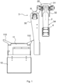
- the translation section 30 is translated upwards, so as to position the rotation section 31 above the bottles 2, allowing the conveyor belt 4 to position the bottles 2 in the pick-up and release area 34.
- the bottles 2 are delivered in the pick-up and drop zone 34 from the conveyor belt 4 and are therefore in the initial position in which they are placed erect with the neck 20 facing upwards.
- the translation section 30 is lowered until the grippers 32 provided on the rotation section 31 are brought to the two diametrically opposite gripping areas of the body of the bottles. In this position the grippers 32 grasp the bottles 2, which then become integral with the rotation section 31.
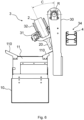
- the rotation section 31 is then rotated to a pre-immersion position, illustrated in Figure 3 .
- the longitudinal axis of each bottle 2 has an inclination A with respect to the horizontal plane comprised between 35° and 80°.
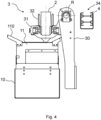
- the rotation section 31 then continues its rotation until the bottles 2 are brought into an immersion position, in which the bottles 2 have the neck 20 facing downwards and immersed in the bath of sealing material in the molten state provided in the tank 11.
- the immersion position is preferably the one illustrated in Figure 4 , in which the bottles 2 are arranged with their own longitudinal in a vertical position vertical axis and immerse the neck 20 for most of its extension.
- the translation section 30 is being raised, to extract the bottles from the tank 11, and the rotation section 31 is rotated in the opposite direction compared to that of the previous steps until the bottles 2 are brought to a first dripping position, illustrated in figure 5 .
- the bottles 20 are completely extracted from the bath of sealing material and have the neck facing downwards, each with its own longitudinal axis inclined with respect to a vertical plane.
- the inclination B of the longitudinal axis of the bottles with respect to the vertical plane is comprised between 20° and 80°.
- the first dripping position provides the neck 20 of the bottle 2 inclined in the direction of removal from the pick-up and drop zone 34.
- the bottles 2 are kept in this first dripping position for the time needed to remove a large part of the excess sealing material from the capsule just formed.
- the rotation section 31 is then rotated again in the direction of rotation of the first phases to bring the bottles 2 into a second dripping position, illustrated in figure 6 .
- the bottles 2 are completely extracted from the bath of sealing material and have the neck 20 facing downwards with its longitudinal axis inclined with respect to the vertical plane in the opposite direction compared to the first dripping position. Therefore, in the preferred embodiment illustrated in the figures, the second dripping position provides the neck 20 of the bottles 2 inclined in the direction of approaching the pick-up and drop zone 34 .
- the inclination C of the longitudinal axis of the bottles 2 compared to the vertical plane is comprised between 5° and 45°.
- the bottles 2 are kept in this second dripping position for the time needed to remove the material in excess completely and to make the distribution of the material in the capsule homogeneous.
- the rotation section 31 is then rotated in the direction of rotation opposite to that of the first phases to bring the bottles 2 to the final position, in which the bottles 2 are in the pick-up and drop area 34 in an upright position with the neck 20 facing the top, as shown in figure 7 .
- bottles 2 When the bottles 2 are returned to their final position, they are released on the conveyor belt 4 by the grippers 32.
- the translation section 30 is then raised returning to the position illustrated in figure 1 .
- the bottles 2 with the capsule formed are then removed by the conveyor belt 4 and a new set of bottles 2 still to be treated is brought into the pick-up and release area 34 by the conveyor belt 4, to start a new cycle of the method.
- the removed bottles 2 can therefore optionally enter a stamping station downstream of the pick-up and release area 34.
- the machine is equipped with automated control means for carrying out the movements described above, in particular an electronic control unit for controlling the driving means of the translation section 30 and the rotation section 31 respectively.
- an electronic control unit for controlling the driving means of the translation section 30 and the rotation section 31 respectively.
- the machine is provided with a user interface, through which the residence times in the various positions in the light of the sealing material used and / or the room temperature can be modified to obtain the desired capsule.
Landscapes
- Filling Of Jars Or Cans And Processes For Cleaning And Sealing Jars (AREA)
- Closing Of Containers (AREA)
Claims (8)
- Verfahren zum Abdichten der Mündung mindestens einer Flasche (2) durch Erstellen einer Kapsel aus Dichtungsmaterial um mindestens den Hals (20) der Flasche (2), einschließlich der folgenden aufeinanderfolgenden Schritte:a) Rotation oder Rototranslation der Flasche (2) um eine horizontale Achse (R) aus einer Ausgangsposition in eine Eintauchposition, in der der Hals (20) der Flasche (2) nach unten weist und zumindest teilweise in einem geschmolzenen Zustand in ein Bad des Dichtungsmaterials eingetaucht ist;b) Rototranslation der Flasche (2) um die horizontale Achse (R) bis zu einer ersten Tropfposition, in der die Flasche (2) vollständig aus dem Dichtungsmaterialbad herausgezogen ist und mit dem Hals (20) nach unten weist und ihre Längsachse im Vergleich zu einer vertikalen Ebene geneigt ist, wobei die vertikale Ebene durch die horizontale Achse (R) der Rotation oder Rototranslation der Flasche verläuft, dadurch gekennzeichnet, dass sie ferner die folgenden aufeinanderfolgenden Schritte umfasst:c) Rotation oder Rototranslation der Flasche (2) um die horizontale Achse (R) in einer zweiten Tropfposition, in der die Flasche (2) vollständig aus dem Dichtungsmaterialbad herausgezogen ist und den Hals (20) nach unten weist und ihre Längsachse in Bezug auf die vertikale Ebene in entgegengesetzter Richtung im Vergleich zu der ersten Tropfposition geneigt ist;d) Rotation oder Rototranslation der Flasche (2) um die horizontale Achse (R) in eine Endstellung.
- Verfahren nach Anspruch 1, wobei die erste Tropfposition und die zweite Tropfposition alternativ zwei diametral gegenüberliegende Punkte der Endkante des Flaschenhalses als unteren Extrempunkt der Flasche identifizieren.
- Verfahren nach einem oder mehreren der vorhergehenden Ansprüche, bei dem die Flasche (2) zunächst in der Ausgangsstellung ergriffen und schließlich in der Endstellung freigegeben wird, in der die Flasche (2) mit dem Hals (20) nach oben gerichtet aufgerichtet wird.
- Verfahren nach einem oder mehreren der vorhergehenden Ansprüche, wobei die Neigung (B) der Längsachse der Flasche (2) in Bezug auf die vertikale Ebene in der ersten Tropfposition zwischen 20° und 80° liegt.
- Verfahren nach einem oder mehreren der vorhergehenden Ansprüche, wobei die Neigung (C) der Längsachse der Flasche in Bezug auf die vertikale Ebene in der zweiten Tropfposition zwischen 5° und 45° liegt.
- Maschine zum Abdichten der Mündung mindestens einer Flasche (2) durch Erzeugen einer Kapsel aus Dichtungsmaterial um mindestens den Hals (20) der Flasche, umfassend einen Boden (10), einen Tank (11) für ein Dichtungsmaterial in geschmolzenem Zustand, einen beweglich an dem Boden (10) befestigten Kopf (3), der mit Rotationsmitteln (31) um eine horizontale Achse (R) und Translationsmitteln (30) entlang einer vertikalen Achse versehen ist und mit Greifmitteln (32) für eine oder mehrere Flaschen (2) versehen ist, und ferner umfassend eine Steuereinheit zum Steuern der Rotationsmittel und der Translationsmittel des Kopfes,
dadurch gekennzeichnet, dass
die Steuereinheit dazu konfiguriert ist, das Rotationsmittel und das Translationsmittel des Kopfes zu betreiben, um das Verfahren nach einem oder mehreren der Ansprüche 1 bis 5 durchzuführen. - Maschine nach Anspruch 6, wobei die Greifmittel (32) konfiguriert sind, um eine Vielzahl von Flaschen (2) zu greifen, die nebeneinander angeordnet sind.
- Maschine nach Anspruch 6 oder 7, bei der ein Aufnahme- und Abgabebereich (34) für die Flaschen (2) durch die Greifmittel (32) vorgesehen ist, wobei ein Förderband (4) für die Zuführung der Flaschen (2) im Aufnahme- und Abgabebereich (34) und für die Entnahme der Flaschen (2) aus dem Aufnahme- und Abgabebereich (34) vorgesehen ist.
Applications Claiming Priority (1)
| Application Number | Priority Date | Filing Date | Title |
|---|---|---|---|
| IT102019000005294A IT201900005294A1 (it) | 2019-04-05 | 2019-04-05 | Macchina e metodo per sigillare l’imboccatura di una o più bottiglie |
Publications (3)
| Publication Number | Publication Date |
|---|---|
| EP3733587A1 EP3733587A1 (de) | 2020-11-04 |
| EP3733587B1 true EP3733587B1 (de) | 2023-10-25 |
| EP3733587C0 EP3733587C0 (de) | 2023-10-25 |
Family
ID=67262845
Family Applications (1)
| Application Number | Title | Priority Date | Filing Date |
|---|---|---|---|
| EP20167976.8A Active EP3733587B1 (de) | 2019-04-05 | 2020-04-03 | Vorrichtung und verfahren zum abdichten eines flaschenhalses |
Country Status (2)
| Country | Link |
|---|---|
| EP (1) | EP3733587B1 (de) |
| IT (1) | IT201900005294A1 (de) |
Families Citing this family (1)
| Publication number | Priority date | Publication date | Assignee | Title |
|---|---|---|---|---|
| CN115028124B (zh) * | 2022-06-09 | 2024-09-24 | 池州平天湖双招双引发展有限公司 | 一种红酒生产瓶口封蜡装置 |
Family Cites Families (3)
| Publication number | Priority date | Publication date | Assignee | Title |
|---|---|---|---|---|
| US2081478A (en) * | 1934-09-11 | 1937-05-25 | Fernplas Corp | Method of and automatic apparatus for coating bottle necks |
| FR2698345B1 (fr) * | 1992-11-25 | 1995-06-02 | Rene Mainguet | Machine de pose de cire sur des bouteilles. |
| FR3001951A1 (fr) * | 2013-02-14 | 2014-08-15 | Guy Bertrand | Procede d'enrobage du goulot d'une bouteille, ou d'une partie d'ouverture d'un recipient similaire, et machine de mise en œuvre de ce procede |
-
2019
- 2019-04-05 IT IT102019000005294A patent/IT201900005294A1/it unknown
-
2020
- 2020-04-03 EP EP20167976.8A patent/EP3733587B1/de active Active
Also Published As
| Publication number | Publication date |
|---|---|
| EP3733587C0 (de) | 2023-10-25 |
| IT201900005294A1 (it) | 2020-10-05 |
| EP3733587A1 (de) | 2020-11-04 |
Similar Documents
| Publication | Publication Date | Title |
|---|---|---|
| EP3162756B1 (de) | System und verfahren zum abdichten von behältern, flaschen, fläschchen und ähnlichem | |
| CN106457650B (zh) | 包括围绕单个主轴线旋转的第一站和第二站的旋转机器 | |
| WO2008086052A2 (en) | Continuous motion spin welding apparatus, system, and method | |
| EP3733587B1 (de) | Vorrichtung und verfahren zum abdichten eines flaschenhalses | |
| EP1996502B1 (de) | Verfahren zur herstellung einer verpackung | |
| CA3011892C (en) | Method of unwrapping a palletised load and device for carrying out said method | |
| US10106388B2 (en) | Container processing machine and method for delivering containers to and/or removing them from a container processing machine | |
| US4231697A (en) | Bottle packaging and unpackaging machine | |
| CN101817492B (zh) | 瓶盖封装方法 | |
| EP3106402B1 (de) | Prozess und vorrichtung zum verschliessen und bedrucken/etikettieren eines behälters | |
| EP2960200A1 (de) | Verschliessmaschine | |
| RU2348574C2 (ru) | Устройство и способ нанесения ярлыков | |
| KR20210124591A (ko) | 화장품 충전 장치 및 그에 따른 화장품 충전 방법 | |
| CN216154214U (zh) | 一种水乳产品自动化包装线 | |
| US7003932B2 (en) | Method and apparatus for applying a threaded cap to a threaded neck of a container | |
| CN113544083B (zh) | 用于由预制坯件制造被灌装的容器的方法和装置 | |
| FR3001451A1 (fr) | Procede et dispositif de fabrication d'articles en verre de forme complexe par centrifugation | |
| EP2714292B1 (de) | Maschine zum waschen von flaschen und der zugehörigen verschlusskappen | |
| CN214828892U (zh) | 一种用于饮料瓶的压盖装置 | |
| JPH03124598A (ja) | 自動開缶・液抜装置 | |
| IT202300017073A1 (it) | Apparato per la sigillatura di una pluralità di contenitori | |
| CN210192696U (zh) | 一种制药设备的翻瓶机构 | |
| EP0640525A1 (de) | Verfahren und Vorrichtung zum Füllen von Verpackungsbehältern | |
| CN112027148B (zh) | 一种水杯生产用拧盖落料流水线 | |
| US2239557A (en) | Means for opening the spouts of spouted containers |
Legal Events
| Date | Code | Title | Description |
|---|---|---|---|
| PUAI | Public reference made under article 153(3) epc to a published international application that has entered the european phase |
Free format text: ORIGINAL CODE: 0009012 |
|
| STAA | Information on the status of an ep patent application or granted ep patent |
Free format text: STATUS: THE APPLICATION HAS BEEN PUBLISHED |
|
| AK | Designated contracting states |
Kind code of ref document: A1 Designated state(s): AL AT BE BG CH CY CZ DE DK EE ES FI FR GB GR HR HU IE IS IT LI LT LU LV MC MK MT NL NO PL PT RO RS SE SI SK SM TR |
|
| AX | Request for extension of the european patent |
Extension state: BA ME |
|
| STAA | Information on the status of an ep patent application or granted ep patent |
Free format text: STATUS: REQUEST FOR EXAMINATION WAS MADE |
|
| 17P | Request for examination filed |
Effective date: 20210504 |
|
| RBV | Designated contracting states (corrected) |
Designated state(s): AL AT BE BG CH CY CZ DE DK EE ES FI FR GB GR HR HU IE IS IT LI LT LU LV MC MK MT NL NO PL PT RO RS SE SI SK SM TR |
|
| GRAP | Despatch of communication of intention to grant a patent |
Free format text: ORIGINAL CODE: EPIDOSNIGR1 |
|
| RIC1 | Information provided on ipc code assigned before grant |
Ipc: B67B 5/05 20060101AFI20230414BHEP |
|
| STAA | Information on the status of an ep patent application or granted ep patent |
Free format text: STATUS: GRANT OF PATENT IS INTENDED |
|
| INTG | Intention to grant announced |
Effective date: 20230525 |
|
| GRAS | Grant fee paid |
Free format text: ORIGINAL CODE: EPIDOSNIGR3 |
|
| GRAA | (expected) grant |
Free format text: ORIGINAL CODE: 0009210 |
|
| STAA | Information on the status of an ep patent application or granted ep patent |
Free format text: STATUS: THE PATENT HAS BEEN GRANTED |
|
| AK | Designated contracting states |
Kind code of ref document: B1 Designated state(s): AL AT BE BG CH CY CZ DE DK EE ES FI FR GB GR HR HU IE IS IT LI LT LU LV MC MK MT NL NO PL PT RO RS SE SI SK SM TR |
|
| REG | Reference to a national code |
Ref country code: GB Ref legal event code: FG4D |
|
| REG | Reference to a national code |
Ref country code: CH Ref legal event code: EP |
|
| REG | Reference to a national code |
Ref country code: DE Ref legal event code: R096 Ref document number: 602020019676 Country of ref document: DE |
|
| REG | Reference to a national code |
Ref country code: IE Ref legal event code: FG4D |
|
| U01 | Request for unitary effect filed |
Effective date: 20231124 |
|
| U07 | Unitary effect registered |
Designated state(s): AT BE BG DE DK EE FI FR IT LT LU LV MT NL PT SE SI Effective date: 20231205 |
|
| PG25 | Lapsed in a contracting state [announced via postgrant information from national office to epo] |
Ref country code: GR Free format text: LAPSE BECAUSE OF FAILURE TO SUBMIT A TRANSLATION OF THE DESCRIPTION OR TO PAY THE FEE WITHIN THE PRESCRIBED TIME-LIMIT Effective date: 20240126 |
|
| PG25 | Lapsed in a contracting state [announced via postgrant information from national office to epo] |
Ref country code: IS Free format text: LAPSE BECAUSE OF FAILURE TO SUBMIT A TRANSLATION OF THE DESCRIPTION OR TO PAY THE FEE WITHIN THE PRESCRIBED TIME-LIMIT Effective date: 20240225 |
|
| PG25 | Lapsed in a contracting state [announced via postgrant information from national office to epo] |
Ref country code: ES Free format text: LAPSE BECAUSE OF FAILURE TO SUBMIT A TRANSLATION OF THE DESCRIPTION OR TO PAY THE FEE WITHIN THE PRESCRIBED TIME-LIMIT Effective date: 20231025 |
|
| PG25 | Lapsed in a contracting state [announced via postgrant information from national office to epo] |
Ref country code: IS Free format text: LAPSE BECAUSE OF FAILURE TO SUBMIT A TRANSLATION OF THE DESCRIPTION OR TO PAY THE FEE WITHIN THE PRESCRIBED TIME-LIMIT Effective date: 20240225 Ref country code: GR Free format text: LAPSE BECAUSE OF FAILURE TO SUBMIT A TRANSLATION OF THE DESCRIPTION OR TO PAY THE FEE WITHIN THE PRESCRIBED TIME-LIMIT Effective date: 20240126 Ref country code: ES Free format text: LAPSE BECAUSE OF FAILURE TO SUBMIT A TRANSLATION OF THE DESCRIPTION OR TO PAY THE FEE WITHIN THE PRESCRIBED TIME-LIMIT Effective date: 20231025 |
|
| PG25 | Lapsed in a contracting state [announced via postgrant information from national office to epo] |
Ref country code: RS Free format text: LAPSE BECAUSE OF FAILURE TO SUBMIT A TRANSLATION OF THE DESCRIPTION OR TO PAY THE FEE WITHIN THE PRESCRIBED TIME-LIMIT Effective date: 20231025 Ref country code: PL Free format text: LAPSE BECAUSE OF FAILURE TO SUBMIT A TRANSLATION OF THE DESCRIPTION OR TO PAY THE FEE WITHIN THE PRESCRIBED TIME-LIMIT Effective date: 20231025 Ref country code: NO Free format text: LAPSE BECAUSE OF FAILURE TO SUBMIT A TRANSLATION OF THE DESCRIPTION OR TO PAY THE FEE WITHIN THE PRESCRIBED TIME-LIMIT Effective date: 20240125 Ref country code: HR Free format text: LAPSE BECAUSE OF FAILURE TO SUBMIT A TRANSLATION OF THE DESCRIPTION OR TO PAY THE FEE WITHIN THE PRESCRIBED TIME-LIMIT Effective date: 20231025 |
|
| U20 | Renewal fee for the european patent with unitary effect paid |
Year of fee payment: 5 Effective date: 20240429 |
|
| PG25 | Lapsed in a contracting state [announced via postgrant information from national office to epo] |
Ref country code: CZ Free format text: LAPSE BECAUSE OF FAILURE TO SUBMIT A TRANSLATION OF THE DESCRIPTION OR TO PAY THE FEE WITHIN THE PRESCRIBED TIME-LIMIT Effective date: 20231025 |
|
| REG | Reference to a national code |
Ref country code: DE Ref legal event code: R097 Ref document number: 602020019676 Country of ref document: DE |
|
| PG25 | Lapsed in a contracting state [announced via postgrant information from national office to epo] |
Ref country code: SK Free format text: LAPSE BECAUSE OF FAILURE TO SUBMIT A TRANSLATION OF THE DESCRIPTION OR TO PAY THE FEE WITHIN THE PRESCRIBED TIME-LIMIT Effective date: 20231025 |
|
| PG25 | Lapsed in a contracting state [announced via postgrant information from national office to epo] |
Ref country code: SM Free format text: LAPSE BECAUSE OF FAILURE TO SUBMIT A TRANSLATION OF THE DESCRIPTION OR TO PAY THE FEE WITHIN THE PRESCRIBED TIME-LIMIT Effective date: 20231025 Ref country code: SK Free format text: LAPSE BECAUSE OF FAILURE TO SUBMIT A TRANSLATION OF THE DESCRIPTION OR TO PAY THE FEE WITHIN THE PRESCRIBED TIME-LIMIT Effective date: 20231025 Ref country code: RO Free format text: LAPSE BECAUSE OF FAILURE TO SUBMIT A TRANSLATION OF THE DESCRIPTION OR TO PAY THE FEE WITHIN THE PRESCRIBED TIME-LIMIT Effective date: 20231025 Ref country code: CZ Free format text: LAPSE BECAUSE OF FAILURE TO SUBMIT A TRANSLATION OF THE DESCRIPTION OR TO PAY THE FEE WITHIN THE PRESCRIBED TIME-LIMIT Effective date: 20231025 |
|
| PLBE | No opposition filed within time limit |
Free format text: ORIGINAL CODE: 0009261 |
|
| STAA | Information on the status of an ep patent application or granted ep patent |
Free format text: STATUS: NO OPPOSITION FILED WITHIN TIME LIMIT |
|
| 26N | No opposition filed |
Effective date: 20240726 |
|
| PG25 | Lapsed in a contracting state [announced via postgrant information from national office to epo] |
Ref country code: MC Free format text: LAPSE BECAUSE OF FAILURE TO SUBMIT A TRANSLATION OF THE DESCRIPTION OR TO PAY THE FEE WITHIN THE PRESCRIBED TIME-LIMIT Effective date: 20231025 |
|
| PG25 | Lapsed in a contracting state [announced via postgrant information from national office to epo] |
Ref country code: MC Free format text: LAPSE BECAUSE OF FAILURE TO SUBMIT A TRANSLATION OF THE DESCRIPTION OR TO PAY THE FEE WITHIN THE PRESCRIBED TIME-LIMIT Effective date: 20231025 |
|
| REG | Reference to a national code |
Ref country code: CH Ref legal event code: PL |
|
| PG25 | Lapsed in a contracting state [announced via postgrant information from national office to epo] |
Ref country code: CH Free format text: LAPSE BECAUSE OF NON-PAYMENT OF DUE FEES Effective date: 20240430 |
|
| PG25 | Lapsed in a contracting state [announced via postgrant information from national office to epo] |
Ref country code: IE Free format text: LAPSE BECAUSE OF NON-PAYMENT OF DUE FEES Effective date: 20240403 |
|
| U20 | Renewal fee for the european patent with unitary effect paid |
Year of fee payment: 6 Effective date: 20250428 |
|
| PGFP | Annual fee paid to national office [announced via postgrant information from national office to epo] |
Ref country code: GB Payment date: 20250428 Year of fee payment: 6 |
|
| PG25 | Lapsed in a contracting state [announced via postgrant information from national office to epo] |
Ref country code: CY Free format text: LAPSE BECAUSE OF FAILURE TO SUBMIT A TRANSLATION OF THE DESCRIPTION OR TO PAY THE FEE WITHIN THE PRESCRIBED TIME-LIMIT; INVALID AB INITIO Effective date: 20200403 |
|
| PG25 | Lapsed in a contracting state [announced via postgrant information from national office to epo] |
Ref country code: HU Free format text: LAPSE BECAUSE OF FAILURE TO SUBMIT A TRANSLATION OF THE DESCRIPTION OR TO PAY THE FEE WITHIN THE PRESCRIBED TIME-LIMIT; INVALID AB INITIO Effective date: 20200403 |