EP3733573B1 - Intermodal container highway and railway transfer system - Google Patents
Intermodal container highway and railway transfer system Download PDFInfo
- Publication number
- EP3733573B1 EP3733573B1 EP18897288.9A EP18897288A EP3733573B1 EP 3733573 B1 EP3733573 B1 EP 3733573B1 EP 18897288 A EP18897288 A EP 18897288A EP 3733573 B1 EP3733573 B1 EP 3733573B1
- Authority
- EP
- European Patent Office
- Prior art keywords
- container
- concave groove
- fixed
- track
- disposed
- Prior art date
- Legal status (The legal status is an assumption and is not a legal conclusion. Google has not performed a legal analysis and makes no representation as to the accuracy of the status listed.)
- Active
Links
- 238000012546 transfer Methods 0.000 title claims description 95
- 230000007246 mechanism Effects 0.000 claims description 208
- 229910000831 Steel Inorganic materials 0.000 claims description 23
- 239000010959 steel Substances 0.000 claims description 23
- 238000000034 method Methods 0.000 description 27
- 238000010586 diagram Methods 0.000 description 16
- 238000010276 construction Methods 0.000 description 3
- 238000013461 design Methods 0.000 description 3
- 238000011161 development Methods 0.000 description 3
- 230000000694 effects Effects 0.000 description 3
- 238000005516 engineering process Methods 0.000 description 3
- 230000000712 assembly Effects 0.000 description 2
- 238000000429 assembly Methods 0.000 description 2
- 230000032258 transport Effects 0.000 description 2
- 230000009286 beneficial effect Effects 0.000 description 1
- 230000001419 dependent effect Effects 0.000 description 1
- 230000007774 longterm Effects 0.000 description 1
- 230000001737 promoting effect Effects 0.000 description 1
- 238000012827 research and development Methods 0.000 description 1
- 238000005728 strengthening Methods 0.000 description 1
Images


Classifications
-
- B—PERFORMING OPERATIONS; TRANSPORTING
- B65—CONVEYING; PACKING; STORING; HANDLING THIN OR FILAMENTARY MATERIAL
- B65G—TRANSPORT OR STORAGE DEVICES, e.g. CONVEYORS FOR LOADING OR TIPPING, SHOP CONVEYOR SYSTEMS OR PNEUMATIC TUBE CONVEYORS
- B65G63/00—Transferring or trans-shipping at storage areas, railway yards or harbours or in opening mining cuts; Marshalling yard installations
- B65G63/02—Transferring or trans-shipping at storage areas, railway yards or harbours or in opening mining cuts; Marshalling yard installations with essentially horizontal transit otherwise than by bridge
- B65G63/022—Transferring or trans-shipping at storage areas, railway yards or harbours or in opening mining cuts; Marshalling yard installations with essentially horizontal transit otherwise than by bridge for articles
- B65G63/025—Transferring or trans-shipping at storage areas, railway yards or harbours or in opening mining cuts; Marshalling yard installations with essentially horizontal transit otherwise than by bridge for articles for containers
-
- B—PERFORMING OPERATIONS; TRANSPORTING
- B65—CONVEYING; PACKING; STORING; HANDLING THIN OR FILAMENTARY MATERIAL
- B65G—TRANSPORT OR STORAGE DEVICES, e.g. CONVEYORS FOR LOADING OR TIPPING, SHOP CONVEYOR SYSTEMS OR PNEUMATIC TUBE CONVEYORS
- B65G63/00—Transferring or trans-shipping at storage areas, railway yards or harbours or in opening mining cuts; Marshalling yard installations
- B65G63/002—Transferring or trans-shipping at storage areas, railway yards or harbours or in opening mining cuts; Marshalling yard installations for articles
- B65G63/004—Transferring or trans-shipping at storage areas, railway yards or harbours or in opening mining cuts; Marshalling yard installations for articles for containers
Definitions
- the disclosure relates to the technical field of container multimodal transportation, and in particular to a container rail-road transfer system.
- the more prominent problems on multimodal transportation include: the poor coordination among roads, railways and waterway transport; the imperfect market environment; the inadequate laws, regulations and standards; and the lag in the application of advanced technologies; and so on.
- the scale of multimodal transportation volume only accounts for 2.9% of the total social freight volume, which is far below the development level of the United States.
- the operating efficiency of multimodal transportation is not high, and the cost for cargo transshipment accounts for about 30% of the total logistics cost, resulting in the domestic logistics cost much higher than the logistics cost of those countries with a developed logistics industry such as the United States, Canada and Europe.
- a container handling line of an electrified railway station generally uses rail-road transit and transfer equipment which is not connected in a network, that is, an electrified railway contact network is disconnected in a container handling area, and rail-mounted gantry cranes, container reach stacker or other lifting equipment are used in the container handling area for loading, unloading and transshipment of containers between railway and road.
- the present disclosure provides a container rail-road transfer system according to claim 1, which solves or partially solves the technical problems in the prior art that the utilization rate of work site on the container handling line of the electrified railway station is lower and the rail-road transfer efficiency is poor.
- the present disclosure provides a container rail-road transfer system for transferring a container on a railway vehicle to a container lorry, and/or transferring a container on a container lorry to a railway vehicle.
- the railway vehicle runs on a railway track under an electrified railway contact network;
- the container rail-road transfer system comprises: a lifting device disposed with respect to the railway track, a two-way side pick-up device, and a container handling device disposed with respect to a parking position of the container lorry, wherein: the two-way side pick-up device is disposed on a carrying platform between the railway track and the parking position of the container lorry, and configured to transfer the container from a position corresponding to the lifting device to a position corresponding to the container handling device, and/or, transfer the container from a position corresponding to the container handling device to a position corresponding to the lifting device; the lifting device is configured to lift the container on the railway vehicle and place the container on the two-way side pick-up device, and/or, lift
- the lifting device comprises a first track disposed on the carrying platform, a second track slidably disposed on the first track, door-shaped support mechanisms symmetrically disposed on two ends of the carrying platform, a number of container twist lock parts disposed under the top of the door-shaped support mechanism at two sides thereof, a first slide driving mechanism, and a second slide driving mechanism.
- the first track is arranged along a length direction of the carrying platform, and is parallel to the railway track;
- the second track is arranged perpendicular to the first track;
- the number of container twist lock parts are configured to cooperate with corner fittings at four corners on the top of the container to lock or unlock the container;
- the door-shaped support mechanism comprises a first telescopic leg, a second telescopic leg, and a crossbeam.
- the container twist lock parts are fixed under the crossbeam on two sides thereof; an fixed end of the first telescopic leg is slidably disposed on the second track, and a movable end of the first telescopic leg is fixedly connected to one end of the crossbeam; a fixed end of the second telescopic leg is fixedly connected to another end of the crossbeam, and a movable end of the second telescopic leg is suspended;
- the first slide driving mechanism is configured to drive the second track to slide along the first track;
- the second slide driving mechanism is configured to drive the door-shaped support mechanisms to slide along the second track, wherein, before raising and lowering the container of the railway vehicle, the door-shaped support mechanisms are slid along the second track so that the second telescopic leg is extended to a side of the railway track; then the door-shaped support mechanisms are slid along the first track so that the positions of the number of container twist lock parts on the door-shaped support mechanisms correspond to the positions of corner fittings on the top of the container;
- the two-way side pick-up device comprises a raising-and-lowering mechanism, a bridging mechanism and a tray mechanism; wherein, the raising-and-lowering mechanism is disposed on the carrying platform; the bridging mechanism is slidably disposed on the raising-and-lowering mechanism; the tray mechanism is slidably disposed on the bridging mechanism; the raising-and-lowering mechanism comprises a raising-and-lowering platform, a number of first telescopic cylinders and a number of first slideways arranged side by side; the number of first telescopic cylinders are arranged on the bottom of the raising-and-lowering platform to drive the raising-and-lowering platform to rise or drop; one end of the first telescopic cylinders is fixed on the carrying platform; the first slideways are disposed on the top of the raising-and-lowering platform and extended in a direction from the railway track to the container lorry; and the bridging mechanism is slidably disposed on the first slideways.
- the bridging mechanism comprises: first concave groove members, the number thereof is the same as the number of the first slideways; a number of first fixed plates connected between the first concave groove members, second slideways disposed on the top of each of the first concave groove members, a first driving component, and a second driving component; the first concave groove members are disposed on and cover the first slideways; the first driving component is configured to drive the first concave groove members to extend from an initial position to the railway track, or to retract from the railway track to the initial position; the second driving component is configured to drive the first concave groove members to extend from the initial position to the parking position of the container lorry, or to retract from the parking position of the container lorry to the initial position; and the tray mechanism is slidably disposed on the second slideways.
- the first driving component comprises a first actuator cylinder and a first connection cylinder fixed at an output end of the first actuator cylinder; the first concave groove members are provided with first cylinder holes, and a rod body of the first connection cylinder can be extended into or exit from the first cylinder holes; an fixed end of the first actuator cylinder is fixed on the raising-and-lowering platform of the raising-and-lowering mechanism, and the output end of the first actuator cylinder is configured to drive the first connection cylinder and the first concave groove members to move;
- the second driving component comprises a second actuator cylinder and a second connection cylinder fixed at an output end of the second actuator cylinder; the first concave groove members are provided with second cylinder holes, and a rod body of the second connection cylinder can be extended into or exit from the second cylinder holes; and an fixed end of the second actuator cylinder is fixed on the raising-and-lowering platform of the raising-and-lowering mechanism, and the output end of the second actuator cylinder is configured to drive the second connection cylinder and the first concave
- the tray mechanism comprises: second concave groove members, the number thereof is the same as the number of the second slideways; a number of second fixed plates connected between the second concave groove members; a number of limit guide stops disposed on the top of the second concave groove members; a number of travel wheels fixed on the side of the second concave groove members; a third driving component, and a fourth driving component; the second concave groove members are disposed on and cover the second slideways; the container is positioned between the limit guide stops after the container is placed on the second concave groove members; the travel wheels are rollingly disposed on the raising-and-lowering platform of the raising-and-lowering mechanism; the third driving component is configured to drive the second concave groove members to extend from an initial position to the railway track, or to retract from the railway track to the initial position; and the fourth driving component is configured to drive the second concave groove members to extend from an initial position to the parking position of the container lorry, or to retract from the parking position of the container lorry to the
- the third driving component comprises a third actuator cylinder and a third connection cylinder fixed at an output end of the third actuator cylinder.
- the second concave groove members are provided with third cylinder holes, and a rod body of the third connection cylinder can be extended into or exit from the third cylinder holes;
- a fixed end of the third actuator cylinder is fixed on the raising-and-lowering platform of the raising-and-lowering mechanism, and the output end of the third actuator cylinder is configured to drive the third connection cylinder and the second concave groove members to move;
- the fourth driving component comprises a fourth actuator cylinder and a fourth connection cylinder fixed at an output end of the fourth actuator cylinder.
- the second concave groove members are provided with fourth cylinder holes, and a rod body of the fourth connection cylinder can be extended into or exit from the fourth cylinder holes; a fixed end of the fourth actuator cylinder is fixed on the raising-and-lowering platform, and the output end of the fourth actuator cylinder is configured to drive the fourth connection cylinder and the second concave groove members to move.
- the container handling device comprises a first top beam, a second top beam, a third top beam, a number of telescopic columns connected under the first top beam and the second top beam, spreader fixed under the third top beam, and a support beam fixed between the telescopic columns under the second top beam.
- the telescopic columns under the first top beam are fixed on the carrying platform, and a distance between the telescopic columns is greater than a length of the container.
- the telescopic columns under the second top beam are disposed on the ground; the second top beam is parallel to the first top beam; and the parking position of the lorry is between the first top beam and the second top beam.
- the third top beam is fixed between the first top beam and the second top beam.
- the spreader is configured to cooperate with corner fittings at four corners on the top of a container to lock or unlock the container.
- the third actuator cylinder is provided inside the telescopic columns, and the third actuator cylinder is configured to drive the telescopic column to extend or retract. An end portion of the first concave groove members is pressed on the support beam after the bridging mechanism is extended.
- the container rail-road transfer system further comprises a mobile platform.
- the mobile platform comprises a first steel rail, a second steel rail and a mobile vehicle.
- the carrying platform is fixed on the mobile vehicle.
- the first steel rail and the second steel rail are parallel to the railway track.
- the mobile vehicle is slidably disposed on the first steel rail.
- the second steel rail is disposed on the ground under the second top beam.
- a roller is disposed at the bottom of the telescopic columns under the second top beam, and the roller is rollingly disposed on the second steel rail.
- the present disclosure also provides a container rail-road transfer system, comprising: a lifting device disposed with respect to a railway track, a two-way side pick-up device, and a container handling device disposed with respect to a parking position of the container lorry, wherein: the two-way side pick-up device is disposed on a carrying platform between the railway track and the parking position of the container lorry.
- the two-way side pick-up device comprises a bridging mechanism and a tray mechanism.
- the bridging mechanism is configured to slide to a position corresponding to the railway track, or slide to a position corresponding to the parking position of the container lorry.
- the tray mechanism is configured to slide on the bridging mechanism to a position corresponding to the railway track or to a position corresponding to the parking position of the container lorry.
- the lifting device comprises: door-shaped support mechanisms disposed at two ends of the carrying platform, and a number of container twist lock parts disposed under the top of the door leg mechanism at two sides thereof.
- the container twist lock parts are configured to lock the container.
- the door-shaped support mechanisms are configured to drive the container to rise or drop, so that the container is lifted from the tray mechanism and placed on the railway vehicle, or the container is lifted from the railway vehicle and placed on the tray mechanism.
- the container handling device comprises: a number of top beams, a number of telescopic columns disposed under the top beams, and a spreader fixed under one of the top beams.
- the spreader is configured to cooperate with corner fittings at four corners on the top of the container to lock or unlock the container.
- the telescopic columns are configured to extend or retract to drive the container to rise or drop, so that the container is lifted from the tray mechanism and placed on the container lorry, or the container is lifted from the container lorry and placed on the tray mechanism.
- the container on the railway vehicle can be transferred to the container lorry and/or the container on the container lorry can be transferred to the railway vehicle without changing the position of the electrified railway contact network, so as to ensure that a space occupied by a container handling area is smaller, thereby making the construction of the entire system convenient and flexible, and adapted to the design of the existing electrified railway contact network.
- the two-way side pick-up device is disposed on the carrying platform between the railway track and the parking position of the container lorry, and is used to transfer a container from a position corresponding to the lifting device to a position corresponding to the container handling device, and/or transfer a container from a position corresponding to the container handling device to a position corresponding to the lifting device.
- the two-way side pick-up device can horizontally move the container between the railway vehicle and the container lorry, which makes the container transshipment process stable and safe, and avoids the interference between the container rail-road transfer system and the electrified railway contact network during the transshipment process.
- the container rail-road transfer system of the present disclosure is simplified and occupies a smaller space, thereby simplifying the transfer procedures and improving the transfer efficiency.
- the lifting device which is used to lift a container on the railway vehicle and place the container on the two-way side pick-up device, and/or lift a container on the two-way side pick-up device and place the container on the railway vehicle, a container at the position of the railway vehicle can be lifted and/or placed conveniently and quickly, thereby improving lifting efficiency during the transshipment process.
- the structure of the container rail-road transfer system of the present disclosure is simplified, and the cost thereof is reduced.
- the container handling device which is used to lift the container on the container lorry and place the container on the two-way side pick-up device, and/or lift a container on the two-way side pick-up device and place the container on the container lorry
- the container at the position of the container lorry can be lifted and/or placed conveniently and quickly, thereby improving lifting efficiency during the transshipment process.
- the structure of the container rail-road transfer system of the present disclosure is simplified, and the cost thereof is reduced.
- the container rail-road transfer system provided by the present disclosure can effectively solve the technical problems in the prior art that the utilization rate of working site on a container handling line of the electrified railway station is lower and the rail-road transfer efficiency is lower, and realize the following effects: there is no interference on the electrified railway contact network; the rail-road transfer procedures are simplified; the operating cost of the container rail-road transfer system is reduced; and the utilization rate of working site and the rail-road transfer efficiency are both improved.
- One or more embodiments of the present application provide a container rail-road transfer system, which solves or partially solves the technical problems in the prior art that the utilization rate of work site on the container handling line of the electrified railway station is lower and the rail-road transfer efficiency is poor.
- the container on the railway vehicle can be transferred to the container lorry, and/or the container on the container lorry can be transferred to the railway vehicle, without changing the position of the electrified railway contact network, so as to ensure that a space occupied by a container handling area is smaller, thereby making the construction of the entire system convenient and flexible, and well adapted to the design of the existing electrified railway contact network.
- the two-way side pick-up device enables the container to move horizontally between the railway container flat car and the container lorry, which makes the container transshipment process stable and safe, and avoids the interference between the container rail-road transfer system and the electrified railway contact network during the transshipment process. Due to the adoption of the two-way side pick-up device, the container rail-road transfer system of the present disclosure is simplified and occupies a smaller space, thereby simplifying the transfer procedures and improving the transfer efficiency.
- the lifting device which is used to lift a container on the railway vehicle and place the container on the two-way side pick-up device, and/or lift a container on the two-way side pick-up device and place the container on the railway vehicle, a container at the position of the railway vehicle can be lifted and/or placed conveniently and quickly, thereby improving lifting efficiency during the transshipment process.
- the structure of the container rail-road transfer system of the present disclosure is simplified, and the cost thereof is reduced.
- the container handling device which is used to lift the container on the container lorry and place the container on the two-way side pick-up device, and/or lift a container on the two-way side pick-up device and place the container on the container lorry
- the container at the position of the container lorry can be lifted and/or placed conveniently and quickly, thereby improving lifting efficiency during the transshipment process.
- the structure of the container rail-road transfer system of the present disclosure is simplified, and the cost thereof is reduced.
- the container rail-road transfer system provided by the present disclosure can effectively solve the technical problems in the prior art that the utilization rate of working site on a container handling line of the electrified railway station is lower and the rail-road transfer efficiency is lower, and realize the following effects: there is no interference on the electrified railway contact network; the rail-road transfer procedures are simplified; the operating cost of the container rail-road transfer system is reduced; and the utilization rate of working site and the rail-road transfer efficiency are both improved.
- one or more embodiments of the present disclosure provide a container rail-road transfer system for transferring a container 6 on a rail vehicle to a container lorry, and/or transferring the container 6 on the container lorry to the railway vehicle; the railway vehicle runs on the railway track under an electrified railway contact network.
- the container rail-road transfer system comprises: a lifting device 2 disposed with respect to the railway track, a two-way side pick-up device 4 and a container handling device 1 disposed with respect to a parking position of the container lorry.
- the railway vehicle in one or more embodiments is a railway container flat car 7 that transports the container 6.
- the two-way side pick-up device 4 is disposed on a carrying platform 3 between the railway track and the parking position of the container lorry; the two-way side pick-up device 4 is used to transfer the container 6 from a position corresponding to the lifting device 2 to a position corresponding to the container handling device 1, and/or, transfer the container 6 from a position corresponding to the container handling device 1 to a position corresponding to the lifting device 2.
- the lifting device 2 is used to lift the container 6 on the railway vehicle and place the container 6 on the two-way side pick-up device 4, and/or to lift the container 6 on the two-way side pick-up device 4 and place the container 6 on the rail vehicle.
- the container handling device 1 is used to lift the container 6 on the container lorry and place the container 6 on the two-way side pick-up device 4, and/or to lift the container 6 on the two-way side pick-up device 4 and place the container 6 on the container lorry.
- the operating principle of the container rail-road transfer system is as below: after the railway vehicle stops at the loading and unloading station site, the lifting device 2 lifts the container 6; then, the two-way side pick-up device 4 moves to a position corresponding to the lifting device 2 , and the lifting device 2 places the container 6 on the two-way side pick-up device 4; and then, the two-way side pick-up device 4 transfers the container 6 from a side of the railway track to a side of the container lorry, and the container handling device 1 lifts the container 6 on the two-way side pick-up device 4; finally, the two-way side pick-up device 4 returns to its initial position, and the container lorry runs to the parking position corresponding to the container handling device 1; thereafter, the container handling device 1 places the container 6 on the container lorry.
- the operating principle of the container rail-road transfer system is as below: after the railway vehicle stops at the loading and unloading station site, the lifting device 2 lifts the container 6; then, the two-way side pick-up
- the container 6 on the railway vehicle can be transferred to the container lorry, and/or the container 6 on the container lorry can be transferred to the railway vehicle, without changing the position of the electrified railway contact network, so as to ensure that a space occupied by a container handling area is smaller, thereby making the construction of the entire system convenient and flexible, and well adapted to the design of the existing electrified railway contact network.
- the two-way side pick-up device 4 enables the container 6 to move horizontally between the railway vehicle and the container lorry, which makes the container transshipment process stable and safe, and avoids the interference between the container rail-road transfer system and the electrified railway contact network during the transshipment process. Due to the adoption of the two-way side pick-up device, the container rail-road transfer system of the present disclosure is simplified and occupies a smaller space, thereby simplifying the transfer procedures and improving the transfer efficiency.
- one or more embodiments of the present disclosure also provides a container rail-road transfer system, which comprises: a lifting device 2 disposed with respect to a railway track, a two-way side pick-up device 4 and a container handling device 1 disposed with respect to a parking position of a container lorry.
- the two-way side pick-up device 4 is disposed on a carrying platform 3 between the railway track and the parking position of the container lorry.
- the two-way side pick-up device 4 comprises a bridging mechanism 402 and a tray mechanism 401.
- the bridging mechanism 402 may slide to a position corresponding to the rail track, or, slide to a position corresponding to the parking position of the container lorry.
- the tray mechanism 401 may slide on the bridging mechanism 402 to a position corresponding to the railway track or a position corresponding to the parking position of the container lorry.
- the lifting device 2 comprises door-shaped support mechanisms disposed at two ends of the carrying platform 3, and a number of container twist lock parts 204 disposed under the top of the door-shaped support mechanisms at two sides.
- the container twist lock parts 204 are configured to lock the container 6, and the door-shaped support mechanisms are configured to drive the container 6 to rise or drop, so that the container 6 is lifted from the tray mechanism 401 and placed on the railway vehicle, or the container 6 is lifted from the railway vehicle and placed on the tray mechanism 401.
- the container handling device 1 comprises a number of top beams, a number of telescopic columns 101 disposed under the top beams, and a spreader 106 fixed under one of the top beams.
- the spreader 106 is configured to cooperate with corner fittings at four corners on the top of the container 6 to lock or unlock the container 6.
- the telescopic columns 101 may be configured to extend or retract so as to drive the container 6 to rise or drop, so that the container 6 is lifted from the tray mechanism 401 and placed on the container lorry, or the container 6 is lifted from the container lorry and placed on the tray mechanism 401.
- the operating principle of the container rail-road transfer system is as below: after the railway vehicle stops at the loading and unloading station site, the lifting device 2 lifts the container 6; then, the bridge mechanism 402 and the tray mechanism 401 of the two-way side pick-up device 4 moves to a position corresponding to the lifting device 2, and the lifting device 2 places the container 6 on the tray mechanism 401; and then, the bridge mechanism 402 and the tray mechanism 401 transfer the container 6 from the railway track side to the container lorry side, and the container handling device 1 lifts the container 6 on the tray mechanism 401; finally, the bridge mechanism 402 and the tray mechanism 401 return to their initial position, and the container lorry runs to the parking position corresponding to the container handling device 1; thereafter, the container handling device 1 places the container 6 on the container lorry.
- the container rail-road transfer system comprises: a lifting device 2 disposed with respect to a railway track, a two-way side pick-up device 4, and a container handling device 1 disposed with respect to a parking position of a container lorry.
- the two-way side pick-up device 4 comprises a bridging mechanism 402 and a tray mechanism 401.
- the tray mechanism 401 is slidably disposed on the bridging mechanism 402.
- the tray mechanism 401 may slide to a position corresponding to the container handling device 1, and/or, slide to a position corresponding to the lifting device 2.
- the two-way side pick-up device 4 further comprises a raising-and-lowering mechanism 403, which is disposed under the bridging mechanism 402 and is located on the carrying platform 3.
- the raising-and-lowering mechanism 403 is used to carry and drive the bridging mechanism 402 and the tray mechanism 401 to rise or drop.
- the raising-and-lowering mechanism 403 comprises a raising-and-lowering platform 4031, four first telescopic cylinders 4032 and two first slideways 4033 arranged side by side.
- the four first telescopic cylinders 4032 are arranged on four corners of the bottom of the raising-and-lowering platform 4031, and are used to drive the raising-and-lowering platform 4031 to rise or drop, thereby adjusting a horizontal height of the container 6 during the transfer process to adapt to different heights of the railway container flat car 7.
- One end of the first telescopic cylinder 4032 is fixed on the carrying platform 3.
- the first slideway 4033 is disposed on the top of the raising-and-lowering platform 4031 in a direction from the railway track to the container lorry. That is, the direction of the first slideway 4033 is perpendicular to the railway track.
- the bridging mechanism 402 is slidably disposed on the first slideway 4033.
- the raising-and-lowering mechanism 403 further comprises twelve sets of first limit wheels 4035.
- Six sets of first limit wheels 4035 are disposed on one first slideway 4033.
- Two first limit wheels 4035 in each set are respectively disposed on two sides of the first slideway 4033.
- the twelve sets of first limit wheels 4035 can ensure that the upper bridging mechanism 402 moves along a fixed straight line.
- the arrangement of the positions of the six sets of first limit wheels 4035 must satisfy that at least two sets of first limit wheels 4035 play the role of fixing and limiting inside the bridging mechanism 402 under any working condition.
- the first slideway 4033 comprises a number of first roller assemblies arranged side by side.
- the first roller assembly comprises a first wheel seat fixed on the raising-and-lowering platform 4031 and a first roller with both ends hinged on the first wheel seat.
- the bridging mechanism 402 can slide on the first rollers of the first slideway 4033 to reduce frictional resistance and ensure sufficient container transfer capacity.
- the first slideway 4033 is a first slider 4033 fixed on the raising-and-lowering platform 4031, and the bridging mechanism 402 may slide along the first slider 4033.
- the bridging mechanism 402 comprises first concave groove members 4021 the number of which is the same as the number of the first slideways 4033, two first fixed plates 4024 connected between the first concave groove members 4021, second slideway 4022 disposed on the top of the first concave groove member 4021, a first driving component 4034, and a second driving component.
- the first concave groove member 4021 is provided with a groove fitted with the first slideway 4033. The groove has an opening facing downward.
- the first concave groove member 4021 is disposed on and covers the first slideway 4033.
- the first driving component 4034 is configured to drive the first concave groove member 4021 to extend from an initial position to a railway container flat car 7, or retract from the railway container flat car 7 to the initial position. After the first concave groove member 4021 extends to the railway container flat car 7, a bottom of the first concave groove member 4021 is pressed on a top surface of the railway container flat car 7.
- the second driving component 4034 is configured to drive the first concave groove member 4021 to extend from the initial position to a parking position of the container lorry, or to retract from the parking position of the container lorry to the initial position.
- the initial position is directly over the raising-and-lowering platform 4031.
- the tray mechanism 401 is slidably disposed on the second slide 4022.
- the bridging mechanism 402 further comprises twelve sets of second limit wheels 4023.
- Six sets of second limit wheels 4023 are disposed on one second slideway 4022.
- Two second limit wheels 4023 in each set are respectively disposed on two sides of the second slideway 4022.
- Twelve sets of second limit wheels 4023 can ensure that an upper tray mechanism 401 moves along a fixed straight line.
- the arrangement of positions of the six sets of second limit wheels 4023 must satisfy that at least two sets of second limit wheels 4023 play the role of fixing and limiting inside the tray mechanism 401 under any working conditions.
- the second slideway 4022 comprises a number of second roller assemblies arranged side by side.
- the second roller assembly comprises a second wheel seat fixed on the first concave groove member 4021 and a second roller with both ends hinged on the second wheel seat.
- the tray mechanism 401 may slide on the second rollers of the second slideway 4022 to reduce frictional resistance and ensure sufficient container transfer capacity.
- the second slideway 4022 is a second slider fixed on the first concave groove member 4021, and the tray mechanism 401 slides along the second slider.
- the following describes two different structures of the first driving component 4034 and the second driving component.
- the first driving component 4034 comprises a first actuator cylinder and a first connection cylinder fixed at an output end of the first actuator cylinder.
- the first concave groove member 4021 is provided with a first cylinder hole, and a rod body of the first connection cylinder can extend into or exit from the first cylinder hole.
- a fixed end of the first actuator cylinder is fixed on the raising-and-lowering platform 4031 of the raising-and-lowering mechanism 403, and the output end of the first actuator cylinder is configured to drive the first connection cylinder and the first concave groove member 4021 to move.
- the second driving component comprises a second actuator cylinder and a second connection cylinder fixed at an output end of the second actuator cylinder.
- the first concave groove member 4021 is provided with a second cylinder hole, and a rod body of the second connection cylinder can be extended into or exit from the second cylinder hole.
- a fixed end of the second actuator cylinder is fixed on the raising-and-lowering platform 4031 of the raising-and-lowering mechanism 403, and the output end of the second actuator cylinder is configured to drive the second connection cylinder and the first concave groove member 4021 to move.
- the first cylinder hole and the second cylinder hole are respectively provided at the diagonal ends of two first concave groove members 4021.
- the first connection cylinder acts and the rod body thereof extends into the first cylinder hole, and the first actuator cylinder pushes the bridging mechanism 402 to extend.
- the second connection cylinder and the second actuator cylinder do not work.
- the second connection cylinder acts and the rod body thereof extends into the second cylinder hole, and the second actuator cylinder pushes the bridging mechanism 402 to extend.
- the first connection cylinder and the first actuator cylinders do not work.
- a rack and pinion mechanism can also be used to provide a transfer thrust for the first driving component 4034 and the second driving component.
- the tray mechanism 401 comprises a second concave groove member 4013 corresponding to the second slideway 4022, two second fixed plates 4014 connected between the second concave groove members 4013, two limit guide stops 4012 disposed on the top of each second concave groove member 4013, two travel wheels 4015 fixed at a side of each of second concave groove members 4013, a third driving component 4011, and a fourth driving component.
- the second concave groove member 4013 is provided with a groove matching with the second slideway 4022.
- the groove is opened downward and covers the second slideway 4022.
- the top of the limit guide stop 4012 is configured to be tilted toward the middle thereof to facilitate the placement of the container.
- the travel wheel 4015 is rollingly disposed on the raising-and-lowering platform 4031 of the raising-and-lowering mechanism 403.
- the bridging mechanism 402 extends from the initial position, one end of the second concave groove member 4013 rests on the second slideway 4022, and another end thereof is supported on the raising-and-lowering platform 4031 by the travel wheel 4015.
- the third driving component 4011 is configured to drive the second concave groove member 4013 to extend from an initial position to the railway container flat car 7, or retract from the railway container flat car 7 to the initial position.
- the fourth driving component is configured to drive the second concave groove member 4013 to extend from the initial position to the parking position of the container lorry, or retract from the parking position of the container lorry to the initial position.
- the initial position is directly over the raising-and-lowering platform 4031.
- the third driving component 4011 comprises a third actuator cylinder and a third connection cylinder fixed at an output end of the third actuator cylinder.
- the second concave groove member 4013 is provided with a third cylinder hole, and a rod body of the third connection cylinder can extend into or exit from the third cylinder hole.
- a fixed end of the third actuator cylinder is fixed on the raising-and-lowering platform 4031 of the raising-and-lowering mechanism 403, and the output end of the third actuator cylinder is configured to drive the third connection cylinder and the second concave groove member 4013 to move.
- the fourth driving component comprises a fourth actuator cylinder and a fourth connection cylinder fixed at an output end of the fourth actuator cylinder.
- the second concave groove member 4013 is provided with a fourth cylinder hole, and a rod body of the fourth connection cylinder can be extended into or exit from the fourth cylinder hole.
- the fixed end of the fourth actuator cylinder is fixed on the raising-and-lowering platform 4031 of the raising-and-lowering mechanism 403, and the output end of the fourth actuator cylinder is configured to drive the fourth connection cylinder and the second concave groove member 4013 to move.
- the third cylinder hole and the fourth cylinder hole are respectively provided at diagonal ends of two second concave groove members 4013.
- the third connection cylinder acts and the rod body thereof extends into the third cylinder hole, and the third actuator cylinder pushes the tray mechanism 401 to extend.
- the fourth connection cylinder and the fourth actuator cylinder do not work.
- the fourth connection cylinder acts and the rod body thereof extends into the fourth cylinder hole, and the fourth actuator cylinder pushes the tray mechanism 401 to extend.
- the third connection cylinder and the third actuator cylinder do not work.
- a rack and pinion mechanism may also be used to provide a transfer thrust for the third driving component 4011 and the fourth driving component.
- the two-way side pick-up device 4 further comprises an anti-tipping assembly.
- the anti-tipping assembly comprises a horizontal plate 405 disposed on a side of the second concave groove member 4013, and a limit frame 404 disposed on the raising-and-lowering platform 4031.
- the bottom of the limit frame 404 is fixed on the raising-and-lowering platform 4031, and the top thereof is a top plate arranged in parallel with the horizontal plate 405.
- the horizontal plate 405 is fitted under the top plate with a clearance.
- the anti-tipping assembly can prevent the tray mechanism 401 from tipping under its own weight.
- the lifting device 2 comprises a first track 205 disposed on the carrying platform 3, a second track 206 slidably disposed on the first track 205, door-shaped support mechanisms symmetrically disposed at two ends of the carrying platform 3, two container twist lock parts 204 disposed under the top of the door-shaped support mechanisms at two sides, a first slide driving mechanism, and a second slide driving mechanism.
- the first track 205 is arranged along the length direction of the carrying platform 3 and is parallel to the railway track.
- the second track 206 is arranged perpendicular to the first track 205.
- Four container twist lock parts 204 are configured to cooperate with corner fittings at four corners on top of the container 6 to lock or unlock the container 6.
- the door-shaped support mechanism comprises a first telescopic leg 201, a second telescopic leg 202, and a crossbeam 203.
- the container twist lock parts 204 are fixed under the crossbeam 203 at two sides.
- a fixed end of the first telescopic leg 201 is slidably disposed on the second track 206, and a movable end is fixedly connected to one end of the crossbeam 203.
- a fixed end of the second telescopic leg 202 is fixedly connected to another end of the crossbeam 203, and a movable end is in a suspended state.
- the first slide driving mechanism is configured to drive the second track 206 to slide along the first track 205.
- the second slide driving mechanism is configured to drive the door-shaped support mechanisms to slide along the second track 206.
- the second telescopic leg 202 is extended to the side of the railway track. Thereafter, the door-shaped support mechanisms can be slide along the first track 205 so that the four container twist lock parts 204 on the door-shaped support mechanisms correspond to the positions of the corner fittings on the top of the container 6, and then the second telescopic legs 202 are extended to make themselves fixed on the ground on the side of the railway track.
- a first member 207 is fixed on the bottom of the second track 206.
- the first member 207 is provided with a chute on the bottom thereof, and the chute is adapted to the first track 205.
- a first actuator cylinder is disposed inside the first telescopic leg 201 to drive the first telescopic leg 201 to extend or retract.
- a second actuator cylinder is disposed inside the second telescopic leg 202 to drive the second telescopic leg 202 to extend or retract.
- the following describes two specific structures of the first slide driving mechanism and the second slide driving mechanism.
- the first slide driving mechanism and the second slide driving mechanism are hydraulic cylinders.
- a fixed end of the first slide driving mechanism is fixed on the carrying platform 3, and an output end thereof is fixedly connected to the first member 207.
- a fixed end of the second slide driving mechanism is fixed on the first member 207, and an output end thereof is fixedly connected to the first telescopic leg 201.
- the first slide driving mechanism is a motored screw. A fixed end of the motored screw is fixed on the carrying platform 3, and an output end thereof is fixedly connected to the first member 207.
- the second slide driving mechanism is a geared motor 208. A side of the first member 207 is provided as a rack that cooperates with a gear of the geared motor 208.
- the geared motor 208 is fixed on the first telescopic leg 201. When the geared motor 208 works, the gear rotates relative to the side of the first member 207, and thus drives the first telescopic leg 201 to slide along the second track 206.
- the following introduces the container handling device according to one or more embodiments of the present disclosure.
- the container handling device 1 comprises a first top beam 103, a second top beam 104, a third top beam 105, four telescopic columns 101 connected under the first top beam 103 and the second top beam 104, a spreader 106 fixed under the third top beam 105, and a support beam 102.
- Two telescopic columns 101 under the first top beam 103 are fixed on the carrying platform 3, and a distance between the telescopic columns 101 is greater than a length of the container 6.
- Two telescopic columns 101 under the second top beam 104 are disposed on the ground, and the second top beam 104 is parallel to the first top beam 103.
- the parking position of the container lorry is between the first top beam 103 and the second top beam 104.
- the third top beam 105 is fixed between the first top beam 103 and the second top beam 104.
- the spreader 106 is configured to cooperate with corner fittings at four corners on the top of the container 6 to lock or unlock the container 6.
- a third actuator cylinder is disposed inside the telescopic column 101 to drive the telescopic column 101 to extend or retract.
- the support beam 102 is fixed between the telescopic columns 101 under the second top beam 104.
- the support beam 102 is parallel to the second top beam 104.
- the support beam 102 makes the structure of the whole device more stable.
- the support beam 102 can provide support for a lateral movement equipment such as the two-way side pick-up device 4 to ensure that the container 6 is stable and safe during the transfer process. Specifically, a side end of the two-way side pick-up device 4 will fall on the support beam 102 when it moves to the side of the container lorry, so that the container 6 can fall between two support points at the bottom of the two-way side pick-up device 4 to ensure a stable support.
- the operating principle of the container handling device 1 is as below: when the container 6 on the container lorry is transferred to the railway vehicle, the container lorry travels to the parking position, and the telescopic columns 101 descend synchronously, so that the spreader 106 is lowered and locked with the corner fittings on the top of the container 6; then the telescopic columns 101 rise synchronously to lift the container 6; and then the container lorry drives away from the parking position, so that the lateral movement equipment such as the two-way side pick-up device 4 can transfer the container 6 to the railway vehicle on a side thereof.
- the lateral movement equipment such as the two-way side pick-up device 4 transfers the container 6 on the railway vehicle to the parking position of the container lorry, and the telescopic columns 101 of the container handling device 1 descend synchronously so that the spreader 106 is lowered and locked with the corner fittings on the top of the container 6; thereafter, the telescopic columns 101 rise synchronously to lift the container 106, and the lateral movement equipment such as the two-way side pick-up device 4 moves away from the parking position of the container lorry; afterwards, the container lorry enters the parking position, and the telescopic columns 101 descend synchronously to place the container 6 on the container lorry; then the spreader 106 and the corner fittings on the top of the container 6 are unlocked, and the transfer process is completed.
- the container handling device 1 can conveniently and quickly realize the lifting or lowering of the container at the position of the collecting lorry, which improves lifting efficiency during the transfer process. Additionally, by adopting the container handling device 1, the container rail-road transfer system is simplified and the cost thereof is reduced.
- the container rail-road transfer system further comprises a mobile platform 5.
- the mobile platform 5 comprises a first steel rail, a second steel rail, and a mobile vehicle.
- the carrying platform 3 is fixed on the mobile vehicle.
- the first steel rail and the second steel rail are parallel to the railway track.
- the mobile vehicle is slidably disposed on the first steel rail.
- the second steel rail is disposed on the ground below the second top beam 104.
- the bottom of the telescopic column 101 under the second top beam 104 is provided with a roller, and the roller is rollingly disposed on the second steel rail.
- the two-way side pick-up device 4 When the loading and unloading position of the railway container flat car 7 and the loading and unloading position of the container lorry are not in the same place, the two-way side pick-up device 4, the lifting device 2 and the container handling device 1 are moved along the first steel rail and the second steel rail by the moving vehicle, so as to complete container transfer operations at different locations.
- a container 6 being transferred from a container lorry to a railway container flat car 7 is taken as an example to describe the operating principle.
- the container lorry enters a parking position between the first top beam 103 and the second top beam 104 of the container handling device 1, the telescopic columns 101 are retracted synchronously, so that the spreader 106 is lowered to a height that fits with the corner fittings on the top of the container 6.
- the telescopic columns 101 lift the container 6; the bridging mechanism 402 of the two-way side pick-up device 4 is extended and pressed on the support beam of the container handling device 1, and the tray mechanism 401 is extended and located on the bridging mechanism 402; the telescopic columns 101 place the container 6 between the limit guide stops 4012 of the tray mechanism 401, and the spreader 106 is unlocked from the container 6; the spreader 106 rises, and the tray mechanism 401 retracts to its initial position, and the bridging mechanism 402 also retracts to its initial position. Then, the moving vehicle travels as needed to move the container 6 to the position corresponding to the railway container flat car 7.
- the bridging mechanism 402 extends to the railway container flat car 7 and presses on the top surface of the railway container flat car 7 (once the bridging mechanism 402 extends beyond the position of a central axis of the railway container flat car 7, the requirements to load the weight of the tray mechanism 401 and the container 6 can be met).
- the tray mechanism 401 slides on the bridging mechanism 402 to the railway container flat car 7 until the container 6 on the tray mechanism 401 is located right above the railway container flat car 7.
- the lifting device 2 starts to act and slides the door-shaped support mechanisms along the second track 206, and then slides the door-shaped support mechanisms along the first track 205, so that the container twist lock parts 204 on the door-shaped support mechanisms can correspond to the positions of the corner fittings on the top of the container 6.
- the second telescopic legs 202 are extended to fix the second telescopic legs 202 on the ground on a side of the railroad track; and then the tray mechanism 401 slides on the bridging mechanism 402 toward the railway container flat car 7, until the container 6 on the tray mechanism 401 is located right above the railway container flat car 7.
- the door-shaped leg mechanisms are retracted so that the container twist lock parts 204 after being lowered can be locked with the corner fittings on the top of the container 6, and then the door-shaped support mechanisms extend to lift the container 6. After that, the tray mechanism 401 and the bridging mechanism 402 are retracted to their initial positions respectively. Finally, the door-shaped support mechanisms are retracted so that the container 6 can be placed on the railway container flat car 7, and the container twist lock parts 204 and the container 6 are unlocked.
Landscapes
- Loading Or Unloading Of Vehicles (AREA)
Description
- The disclosure relates to the technical field of container multimodal transportation, and in particular to a container rail-road transfer system.
- At present, the development level of multimodal transportation in China is still relatively low, and road transportation has been the mainstay for a long time. The more prominent problems on multimodal transportation include: the poor coordination among roads, railways and waterway transport; the imperfect market environment; the inadequate laws, regulations and standards; and the lag in the application of advanced technologies; and so on. The scale of multimodal transportation volume only accounts for 2.9% of the total social freight volume, which is far below the development level of the United States. The operating efficiency of multimodal transportation is not high, and the cost for cargo transshipment accounts for about 30% of the total logistics cost, resulting in the domestic logistics cost much higher than the logistics cost of those countries with a developed logistics industry such as the United States, Canada and Europe. Strengthening the research and development of the core technology and equipment of the logistics industry, and promoting the industrialization of key technologies and equipment, have become the main development tasks of the national logistics industry in the medium and long term. As of September 1, 2016, there are more than 1,506 container handling stations in 18 railway bureaus across China, and there are huge application prospects for rail-road transit and transfer equipment.
- A container handling line of an electrified railway station generally uses rail-road transit and transfer equipment which is not connected in a network, that is, an electrified railway contact network is disconnected in a container handling area, and rail-mounted gantry cranes, container reach stacker or other lifting equipment are used in the container handling area for loading, unloading and transshipment of containers between railway and road.
- The rail-mounted gantry cranes in the prior art is bulky and costly, and requires a large work site, thereby reducing the available space in a work site. In a transit process, a train arrived at/departing from a station cannot directly enter a handling area, thus shunting and connecting operations are required, which results in a low efficiency in rail-road transshipment. EP patent application
EP0831002A1 discloses a rail-road transfer system for transferring a container between a railway track and a container lorry according to the preamble ofclaim 1, but there is still a need for improved transfer system. - The present disclosure provides a container rail-road transfer system according to
claim 1, which solves or partially solves the technical problems in the prior art that the utilization rate of work site on the container handling line of the electrified railway station is lower and the rail-road transfer efficiency is poor. - The present disclosure provides a container rail-road transfer system for transferring a container on a railway vehicle to a container lorry, and/or transferring a container on a container lorry to a railway vehicle. The railway vehicle runs on a railway track under an electrified railway contact network; the container rail-road transfer system comprises: a lifting device disposed with respect to the railway track, a two-way side pick-up device, and a container handling device disposed with respect to a parking position of the container lorry, wherein: the two-way side pick-up device is disposed on a carrying platform between the railway track and the parking position of the container lorry, and configured to transfer the container from a position corresponding to the lifting device to a position corresponding to the container handling device, and/or, transfer the container from a position corresponding to the container handling device to a position corresponding to the lifting device; the lifting device is configured to lift the container on the railway vehicle and place the container on the two-way side pick-up device, and/or, lift the container on the two-way side pick-up device and place the container on the railway vehicle; and the container handling device is configured to lift the container on the container lorry and place the container on the two-way side pick-up device, and/or lift the container on the two-way side pick-up device and place the container on the container lorry.
- The lifting device comprises a first track disposed on the carrying platform, a second track slidably disposed on the first track, door-shaped support mechanisms symmetrically disposed on two ends of the carrying platform, a number of container twist lock parts disposed under the top of the door-shaped support mechanism at two sides thereof, a first slide driving mechanism, and a second slide driving mechanism. the first track is arranged along a length direction of the carrying platform, and is parallel to the railway track; the second track is arranged perpendicular to the first track; the number of container twist lock parts are configured to cooperate with corner fittings at four corners on the top of the container to lock or unlock the container; the door-shaped support mechanism comprises a first telescopic leg, a second telescopic leg, and a crossbeam. The container twist lock parts are fixed under the crossbeam on two sides thereof; an fixed end of the first telescopic leg is slidably disposed on the second track, and a movable end of the first telescopic leg is fixedly connected to one end of the crossbeam; a fixed end of the second telescopic leg is fixedly connected to another end of the crossbeam, and a movable end of the second telescopic leg is suspended; the first slide driving mechanism is configured to drive the second track to slide along the first track; the second slide driving mechanism is configured to drive the door-shaped support mechanisms to slide along the second track, wherein, before raising and lowering the container of the railway vehicle, the door-shaped support mechanisms are slid along the second track so that the second telescopic leg is extended to a side of the railway track; then the door-shaped support mechanisms are slid along the first track so that the positions of the number of container twist lock parts on the door-shaped support mechanisms correspond to the positions of corner fittings on the top of the container; and then, the second telescopic leg is extended to be fixed on the ground on the side of the railway track. Embodiments are defined in the dependent claims.
- In some embodiments, the two-way side pick-up device comprises a raising-and-lowering mechanism, a bridging mechanism and a tray mechanism; wherein, the raising-and-lowering mechanism is disposed on the carrying platform; the bridging mechanism is slidably disposed on the raising-and-lowering mechanism; the tray mechanism is slidably disposed on the bridging mechanism; the raising-and-lowering mechanism comprises a raising-and-lowering platform, a number of first telescopic cylinders and a number of first slideways arranged side by side; the number of first telescopic cylinders are arranged on the bottom of the raising-and-lowering platform to drive the raising-and-lowering platform to rise or drop; one end of the first telescopic cylinders is fixed on the carrying platform; the first slideways are disposed on the top of the raising-and-lowering platform and extended in a direction from the railway track to the container lorry; and the bridging mechanism is slidably disposed on the first slideways.
- In some embodiments, the bridging mechanism comprises: first concave groove members, the number thereof is the same as the number of the first slideways; a number of first fixed plates connected between the first concave groove members, second slideways disposed on the top of each of the first concave groove members, a first driving component, and a second driving component;
the first concave groove members are disposed on and cover the first slideways; the first driving component is configured to drive the first concave groove members to extend from an initial position to the railway track, or to retract from the railway track to the initial position; the second driving component is configured to drive the first concave groove members to extend from the initial position to the parking position of the container lorry, or to retract from the parking position of the container lorry to the initial position; and the tray mechanism is slidably disposed on the second slideways. - In some embodiments, the first driving component comprises a first actuator cylinder and a first connection cylinder fixed at an output end of the first actuator cylinder; the first concave groove members are provided with first cylinder holes, and a rod body of the first connection cylinder can be extended into or exit from the first cylinder holes; an fixed end of the first actuator cylinder is fixed on the raising-and-lowering platform of the raising-and-lowering mechanism, and the output end of the first actuator cylinder is configured to drive the first connection cylinder and the first concave groove members to move; the second driving component comprises a second actuator cylinder and a second connection cylinder fixed at an output end of the second actuator cylinder; the first concave groove members are provided with second cylinder holes, and a rod body of the second connection cylinder can be extended into or exit from the second cylinder holes; and an fixed end of the second actuator cylinder is fixed on the raising-and-lowering platform of the raising-and-lowering mechanism, and the output end of the second actuator cylinder is configured to drive the second connection cylinder and the first concave groove members to move.
- In some embodiments, the tray mechanism comprises: second concave groove members, the number thereof is the same as the number of the second slideways; a number of second fixed plates connected between the second concave groove members; a number of limit guide stops disposed on the top of the second concave groove members; a number of travel wheels fixed on the side of the second concave groove members; a third driving component, and a fourth driving component; the second concave groove members are disposed on and cover the second slideways; the container is positioned between the limit guide stops after the container is placed on the second concave groove members; the travel wheels are rollingly disposed on the raising-and-lowering platform of the raising-and-lowering mechanism; the third driving component is configured to drive the second concave groove members to extend from an initial position to the railway track, or to retract from the railway track to the initial position; and the fourth driving component is configured to drive the second concave groove members to extend from an initial position to the parking position of the container lorry, or to retract from the parking position of the container lorry to the initial position.
- In some embodiments, the third driving component comprises a third actuator cylinder and a third connection cylinder fixed at an output end of the third actuator cylinder. The second concave groove members are provided with third cylinder holes, and a rod body of the third connection cylinder can be extended into or exit from the third cylinder holes; a fixed end of the third actuator cylinder is fixed on the raising-and-lowering platform of the raising-and-lowering mechanism, and the output end of the third actuator cylinder is configured to drive the third connection cylinder and the second concave groove members to move; the fourth driving component comprises a fourth actuator cylinder and a fourth connection cylinder fixed at an output end of the fourth actuator cylinder. the second concave groove members are provided with fourth cylinder holes, and a rod body of the fourth connection cylinder can be extended into or exit from the fourth cylinder holes; a fixed end of the fourth actuator cylinder is fixed on the raising-and-lowering platform, and the output end of the fourth actuator cylinder is configured to drive the fourth connection cylinder and the second concave groove members to move.
- In some embodiments, the container handling device comprises a first top beam, a second top beam, a third top beam, a number of telescopic columns connected under the first top beam and the second top beam, spreader fixed under the third top beam, and a support beam fixed between the telescopic columns under the second top beam. The telescopic columns under the first top beam are fixed on the carrying platform, and a distance between the telescopic columns is greater than a length of the container. The telescopic columns under the second top beam are disposed on the ground; the second top beam is parallel to the first top beam; and the parking position of the lorry is between the first top beam and the second top beam. The third top beam is fixed between the first top beam and the second top beam. The spreader is configured to cooperate with corner fittings at four corners on the top of a container to lock or unlock the container. The third actuator cylinder is provided inside the telescopic columns, and the third actuator cylinder is configured to drive the telescopic column to extend or retract. An end portion of the first concave groove members is pressed on the support beam after the bridging mechanism is extended.
- In some embodiments, the container rail-road transfer system further comprises a mobile platform. The mobile platform comprises a first steel rail, a second steel rail and a mobile vehicle. The carrying platform is fixed on the mobile vehicle. The first steel rail and the second steel rail are parallel to the railway track. The mobile vehicle is slidably disposed on the first steel rail. The second steel rail is disposed on the ground under the second top beam. A roller is disposed at the bottom of the telescopic columns under the second top beam, and the roller is rollingly disposed on the second steel rail.
- Based on the same inventive concept, the present disclosure also provides a container rail-road transfer system, comprising: a lifting device disposed with respect to a railway track, a two-way side pick-up device, and a container handling device disposed with respect to a parking position of the container lorry, wherein: the two-way side pick-up device is disposed on a carrying platform between the railway track and the parking position of the container lorry. The two-way side pick-up device comprises a bridging mechanism and a tray mechanism. The bridging mechanism is configured to slide to a position corresponding to the railway track, or slide to a position corresponding to the parking position of the container lorry. The tray mechanism is configured to slide on the bridging mechanism to a position corresponding to the railway track or to a position corresponding to the parking position of the container lorry. The lifting device comprises: door-shaped support mechanisms disposed at two ends of the carrying platform, and a number of container twist lock parts disposed under the top of the door leg mechanism at two sides thereof. The container twist lock parts are configured to lock the container. The door-shaped support mechanisms are configured to drive the container to rise or drop, so that the container is lifted from the tray mechanism and placed on the railway vehicle, or the container is lifted from the railway vehicle and placed on the tray mechanism. The container handling device comprises: a number of top beams, a number of telescopic columns disposed under the top beams, and a spreader fixed under one of the top beams. The spreader is configured to cooperate with corner fittings at four corners on the top of the container to lock or unlock the container. The telescopic columns are configured to extend or retract to drive the container to rise or drop, so that the container is lifted from the tray mechanism and placed on the container lorry, or the container is lifted from the container lorry and placed on the tray mechanism.
- The one or more embodiments provided in the present disclosure have at least the following technical effects or advantages:
- With the container rail-road transfer system of the present disclosure including a lifting device, a two-way side pick-up device and a container handling device, the container on the railway vehicle can be transferred to the container lorry and/or the container on the container lorry can be transferred to the railway vehicle without changing the position of the electrified railway contact network, so as to ensure that a space occupied by a container handling area is smaller, thereby making the construction of the entire system convenient and flexible, and adapted to the design of the existing electrified railway contact network. The two-way side pick-up device is disposed on the carrying platform between the railway track and the parking position of the container lorry, and is used to transfer a container from a position corresponding to the lifting device to a position corresponding to the container handling device, and/or transfer a container from a position corresponding to the container handling device to a position corresponding to the lifting device. The two-way side pick-up device can horizontally move the container between the railway vehicle and the container lorry, which makes the container transshipment process stable and safe, and avoids the interference between the container rail-road transfer system and the electrified railway contact network during the transshipment process. Due to the adoption of the two-way side pick-up device, the container rail-road transfer system of the present disclosure is simplified and occupies a smaller space, thereby simplifying the transfer procedures and improving the transfer efficiency. By adopting the lifting device which is used to lift a container on the railway vehicle and place the container on the two-way side pick-up device, and/or lift a container on the two-way side pick-up device and place the container on the railway vehicle, a container at the position of the railway vehicle can be lifted and/or placed conveniently and quickly, thereby improving lifting efficiency during the transshipment process. In addition, by adopting the lifting device, the structure of the container rail-road transfer system of the present disclosure is simplified, and the cost thereof is reduced. By adopting the container handling device which is used to lift the container on the container lorry and place the container on the two-way side pick-up device, and/or lift a container on the two-way side pick-up device and place the container on the container lorry, the container at the position of the container lorry can be lifted and/or placed conveniently and quickly, thereby improving lifting efficiency during the transshipment process. In addition, by adopting the container handling device, the structure of the container rail-road transfer system of the present disclosure is simplified, and the cost thereof is reduced. In this way, the container rail-road transfer system provided by the present disclosure can effectively solve the technical problems in the prior art that the utilization rate of working site on a container handling line of the electrified railway station is lower and the rail-road transfer efficiency is lower, and realize the following effects: there is no interference on the electrified railway contact network; the rail-road transfer procedures are simplified; the operating cost of the container rail-road transfer system is reduced; and the utilization rate of working site and the rail-road transfer efficiency are both improved.
-
-
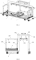
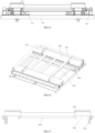
Fig. 1 is a schematic structural diagram of a container rail-road transfer system according to one or more embodiments of the present disclosure; -
Fig. 2 is a left side view ofFig. 1 ; -
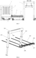
Fig. 3 is a schematic diagram showing a state where a container is lifted by the rail-road transfer system ofFig. 1 ; -
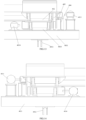
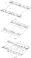
Fig. 4 is a schematic view showing a state where a bridging mechanism and a tray mechanism of the container rail-road transfer system ofFig. 1 carry the container; -
Fig. 5 is a schematic diagram showing a state where the bridging mechanism and the tray mechanism of the container rail-road transfer system ofFig. 1 carry the container and retract to their initial positions; -
Fig. 6 is a schematic diagram showing a state where the bridging mechanism and the tray mechanism of the container rail-road transfer system ofFig. 1 carry the container and extend across a railway vehicle; -
Fig. 7 is a schematic diagram showing a state where the bridging mechanism and the tray mechanism of the container rail-road transfer system ofFig. 1 carry the container and extend across the railway vehicle, and a lifting device lifts the container; -
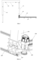
Fig. 8 is a schematic structural diagram of a lifting device of the container rail-road transfer system ofFig. 1 ; -
Fig. 9 is a schematic structural diagram ofFig. 8 from another viewing angle; -
Fig. 10 is a partial enlarged diagram showing the cooperation of a first track, a first member, a second track, and a first telescopic leg ofFig. 8 ; -
Fig. 11 is a schematic structural diagram of a container handling device of the container rail-road transfer system ofFig. 1 ; -
Fig. 12 is a schematic structural diagram of a two-way side pick-up device of the container rail-road transfer system ofFig. 1 ; -
Fig. 13 is a schematic diagram showing a state where a first driving component (or a second driving component) and the bridging mechanism of the two-way side pick-up device ofFig. 12 are separated; -
Fig. 14 is a schematic diagram showing a state where the first driving component (or the second driving component) and the bridging mechanism of the two-way side pick-up device ofFIG. 12 are connected; -
Fig. 15 is a left side view ofFig. 12 ; -
Fig. 16 is a schematic diagram showing a state where the two-way side pick-up device ofFig. 12 is in an initial position; -
Fig. 17 is a left side view of a tray mechanism of the two-way side pick-up device ofFig. 12 ; -
Fig. 18 is a schematic structural diagram of the bridging mechanism of the two-way side pick-up device ofFig. 12 ; -
Fig. 19 is a schematic structural diagram of the raising-and-lowering mechanism of the two-way side pick-up device ofFig. 12 ; and -
Fig. 20 is a schematic structural diagram of the two-way side pick-up device ofFig. 12 when the bridging mechanism is extended. - Reference numerals in the Figures are listed as below:
1 - container handling device; 2 - lifting device; 3 - carrying platform; 4 - two-way side pick-up device; 5 - mobile platform; 6 - container; 7 - railway container flat car; 101 - telescopic column; 102 - support beam; 103 - first top beam; 104 - second top beam; 105 - third top beam; 106 - spreader; 201 - first telescopic leg; 202 - second telescopic leg; 203 - crossbeam; 204 - container twist lock parts; 205 - first track; 206 - second track; 207 - first member; 208 - gear motor; 401 - tray mechanism; 402 - bridging mechanism; 403 - raising-and-lowering mechanism; 404 - stop frame; 405 - horizontal plate; 4011 - third driving component/fourth driving component; 4012 - limit guide stop; 4013 - second concave groove member; 4014 - second fixed plate; 4015 - travel wheel; 4021 - first concave groove member; 4022 - second slideway; 4023 - second limit wheel; 4024 - first fixed plate; 4031 - raising-and-lowering platform; 4032 - first telescopic cylinder; 4033 - first slideway; 4034 - first driving component/second driving component; 4035 - first limit wheel. - One or more embodiments of the present application provide a container rail-road transfer system, which solves or partially solves the technical problems in the prior art that the utilization rate of work site on the container handling line of the electrified railway station is lower and the rail-road transfer efficiency is poor. With the container rail-road transfer system of the present disclosure including a lifting device, a two-way side pick-up device and a container handling device, the container on the railway vehicle can be transferred to the container lorry, and/or the container on the container lorry can be transferred to the railway vehicle, without changing the position of the electrified railway contact network, so as to ensure that a space occupied by a container handling area is smaller, thereby making the construction of the entire system convenient and flexible, and well adapted to the design of the existing electrified railway contact network. The two-way side pick-up device enables the container to move horizontally between the railway container flat car and the container lorry, which makes the container transshipment process stable and safe, and avoids the interference between the container rail-road transfer system and the electrified railway contact network during the transshipment process. Due to the adoption of the two-way side pick-up device, the container rail-road transfer system of the present disclosure is simplified and occupies a smaller space, thereby simplifying the transfer procedures and improving the transfer efficiency. By adopting the lifting device which is used to lift a container on the railway vehicle and place the container on the two-way side pick-up device, and/or lift a container on the two-way side pick-up device and place the container on the railway vehicle, a container at the position of the railway vehicle can be lifted and/or placed conveniently and quickly, thereby improving lifting efficiency during the transshipment process. In addition, by adopting the lifting device, the structure of the container rail-road transfer system of the present disclosure is simplified, and the cost thereof is reduced. By adopting the container handling device which is used to lift the container on the container lorry and place the container on the two-way side pick-up device, and/or lift a container on the two-way side pick-up device and place the container on the container lorry, the container at the position of the container lorry can be lifted and/or placed conveniently and quickly, thereby improving lifting efficiency during the transshipment process. In addition, by adopting the container handling device, the structure of the container rail-road transfer system of the present disclosure is simplified, and the cost thereof is reduced. In this way, the container rail-road transfer system provided by the present disclosure can effectively solve the technical problems in the prior art that the utilization rate of working site on a container handling line of the electrified railway station is lower and the rail-road transfer efficiency is lower, and realize the following effects: there is no interference on the electrified railway contact network; the rail-road transfer procedures are simplified; the operating cost of the container rail-road transfer system is reduced; and the utilization rate of working site and the rail-road transfer efficiency are both improved.
- Referring to
Figs. 1 and 2 , one or more embodiments of the present disclosure provide a container rail-road transfer system for transferring acontainer 6 on a rail vehicle to a container lorry, and/or transferring thecontainer 6 on the container lorry to the railway vehicle; the railway vehicle runs on the railway track under an electrified railway contact network. The container rail-road transfer system comprises: a liftingdevice 2 disposed with respect to the railway track, a two-way side pick-updevice 4 and acontainer handling device 1 disposed with respect to a parking position of the container lorry. The railway vehicle in one or more embodiments is a railway containerflat car 7 that transports thecontainer 6. - In some embodiments, the two-way side pick-up
device 4 is disposed on a carryingplatform 3 between the railway track and the parking position of the container lorry; the two-way side pick-updevice 4 is used to transfer thecontainer 6 from a position corresponding to thelifting device 2 to a position corresponding to thecontainer handling device 1, and/or, transfer thecontainer 6 from a position corresponding to thecontainer handling device 1 to a position corresponding to thelifting device 2. - In some embodiments, the
lifting device 2 is used to lift thecontainer 6 on the railway vehicle and place thecontainer 6 on the two-way side pick-updevice 4, and/or to lift thecontainer 6 on the two-way side pick-updevice 4 and place thecontainer 6 on the rail vehicle. - In some embodiments, the
container handling device 1 is used to lift thecontainer 6 on the container lorry and place thecontainer 6 on the two-way side pick-updevice 4, and/or to lift thecontainer 6 on the two-way side pick-updevice 4 and place thecontainer 6 on the container lorry. - In some embodiments, when the
container 6 on the railway vehicle is transferred to the container lorry, the operating principle of the container rail-road transfer system is as below: after the railway vehicle stops at the loading and unloading station site, thelifting device 2 lifts thecontainer 6; then, the two-way side pick-updevice 4 moves to a position corresponding to thelifting device 2 , and thelifting device 2 places thecontainer 6 on the two-way side pick-updevice 4; and then, the two-way side pick-updevice 4 transfers thecontainer 6 from a side of the railway track to a side of the container lorry, and thecontainer handling device 1 lifts thecontainer 6 on the two-way side pick-updevice 4; finally, the two-way side pick-updevice 4 returns to its initial position, and the container lorry runs to the parking position corresponding to thecontainer handling device 1; thereafter, thecontainer handling device 1 places thecontainer 6 on the container lorry. In addition, when thecontainer 6 on the container lorry is transferred to the railway vehicle, the operating principle of the container rail-road transfer system is contrary to the above process and will not be described in detail. - With the container rail-road transfer system of the present disclosure, the
container 6 on the railway vehicle can be transferred to the container lorry, and/or thecontainer 6 on the container lorry can be transferred to the railway vehicle, without changing the position of the electrified railway contact network, so as to ensure that a space occupied by a container handling area is smaller, thereby making the construction of the entire system convenient and flexible, and well adapted to the design of the existing electrified railway contact network. The two-way side pick-updevice 4 enables thecontainer 6 to move horizontally between the railway vehicle and the container lorry, which makes the container transshipment process stable and safe, and avoids the interference between the container rail-road transfer system and the electrified railway contact network during the transshipment process. Due to the adoption of the two-way side pick-up device, the container rail-road transfer system of the present disclosure is simplified and occupies a smaller space, thereby simplifying the transfer procedures and improving the transfer efficiency. - Based on the same inventive concept, referring to
Figs. 1 and 2 , one or more embodiments of the present disclosure also provides a container rail-road transfer system, which comprises: a liftingdevice 2 disposed with respect to a railway track, a two-way side pick-updevice 4 and acontainer handling device 1 disposed with respect to a parking position of a container lorry. - In some embodiments, the two-way side pick-up
device 4 is disposed on a carryingplatform 3 between the railway track and the parking position of the container lorry. The two-way side pick-updevice 4 comprises abridging mechanism 402 and atray mechanism 401. Thebridging mechanism 402 may slide to a position corresponding to the rail track, or, slide to a position corresponding to the parking position of the container lorry. Thetray mechanism 401 may slide on thebridging mechanism 402 to a position corresponding to the railway track or a position corresponding to the parking position of the container lorry. - In some embodiments, the
lifting device 2 comprises door-shaped support mechanisms disposed at two ends of the carryingplatform 3, and a number of containertwist lock parts 204 disposed under the top of the door-shaped support mechanisms at two sides. The containertwist lock parts 204 are configured to lock thecontainer 6, and the door-shaped support mechanisms are configured to drive thecontainer 6 to rise or drop, so that thecontainer 6 is lifted from thetray mechanism 401 and placed on the railway vehicle, or thecontainer 6 is lifted from the railway vehicle and placed on thetray mechanism 401. - In some embodiments, the
container handling device 1 comprises a number of top beams, a number oftelescopic columns 101 disposed under the top beams, and aspreader 106 fixed under one of the top beams. Thespreader 106 is configured to cooperate with corner fittings at four corners on the top of thecontainer 6 to lock or unlock thecontainer 6. Thetelescopic columns 101 may be configured to extend or retract so as to drive thecontainer 6 to rise or drop, so that thecontainer 6 is lifted from thetray mechanism 401 and placed on the container lorry, or thecontainer 6 is lifted from the container lorry and placed on thetray mechanism 401. - In some embodiments, referring to
Figs. 3-7 , when thecontainer 6 on the railway vehicle is transferred to the container lorry, the operating principle of the container rail-road transfer system is as below: after the railway vehicle stops at the loading and unloading station site, thelifting device 2 lifts thecontainer 6; then, thebridge mechanism 402 and thetray mechanism 401 of the two-way side pick-updevice 4 moves to a position corresponding to thelifting device 2, and thelifting device 2 places thecontainer 6 on thetray mechanism 401; and then, thebridge mechanism 402 and thetray mechanism 401 transfer thecontainer 6 from the railway track side to the container lorry side, and thecontainer handling device 1 lifts thecontainer 6 on thetray mechanism 401; finally, thebridge mechanism 402 and thetray mechanism 401 return to their initial position, and the container lorry runs to the parking position corresponding to thecontainer handling device 1; thereafter, thecontainer handling device 1 places thecontainer 6 on the container lorry. In addition, when thecontainer 6 on the container lorry is transferred to the railway vehicle, the operating principle of the container rail-road transfer system is contrary to the above process and will not be described in detail. - The following describes the container rail-road transfer system provided in the present disclosure in detail with reference to the accompanying drawings and specific embodiments.
- The container rail-road transfer system according to one or more embodiments of the present disclosure comprises: a lifting
device 2 disposed with respect to a railway track, a two-way side pick-updevice 4, and acontainer handling device 1 disposed with respect to a parking position of a container lorry. - The specific structure of the two-way side pick-up
device 4 according to one or more embodiments of the present disclosure will be described below. - Referring to
Figs. 12-20 , the two-way side pick-updevice 4 comprises abridging mechanism 402 and atray mechanism 401. Thetray mechanism 401 is slidably disposed on thebridging mechanism 402. Thetray mechanism 401 may slide to a position corresponding to thecontainer handling device 1, and/or, slide to a position corresponding to thelifting device 2. The two-way side pick-updevice 4 further comprises a raising-and-loweringmechanism 403, which is disposed under thebridging mechanism 402 and is located on the carryingplatform 3. The raising-and-loweringmechanism 403 is used to carry and drive thebridging mechanism 402 and thetray mechanism 401 to rise or drop. - The raising-and-lowering
mechanism 403 comprises a raising-and-loweringplatform 4031, four firsttelescopic cylinders 4032 and twofirst slideways 4033 arranged side by side. The four firsttelescopic cylinders 4032 are arranged on four corners of the bottom of the raising-and-loweringplatform 4031, and are used to drive the raising-and-loweringplatform 4031 to rise or drop, thereby adjusting a horizontal height of thecontainer 6 during the transfer process to adapt to different heights of the railway containerflat car 7. One end of the firsttelescopic cylinder 4032 is fixed on the carryingplatform 3. Thefirst slideway 4033 is disposed on the top of the raising-and-loweringplatform 4031 in a direction from the railway track to the container lorry. That is, the direction of thefirst slideway 4033 is perpendicular to the railway track. Thebridging mechanism 402 is slidably disposed on thefirst slideway 4033. - Referring to
Fig. 19 , the raising-and-loweringmechanism 403 further comprises twelve sets offirst limit wheels 4035. Six sets offirst limit wheels 4035 are disposed on onefirst slideway 4033. Twofirst limit wheels 4035 in each set are respectively disposed on two sides of thefirst slideway 4033. The twelve sets offirst limit wheels 4035 can ensure that theupper bridging mechanism 402 moves along a fixed straight line. The arrangement of the positions of the six sets offirst limit wheels 4035 must satisfy that at least two sets offirst limit wheels 4035 play the role of fixing and limiting inside thebridging mechanism 402 under any working condition. - A specific structure of the first slideway is described below.
- The
first slideway 4033 comprises a number of first roller assemblies arranged side by side. The first roller assembly comprises a first wheel seat fixed on the raising-and-loweringplatform 4031 and a first roller with both ends hinged on the first wheel seat. Thebridging mechanism 402 can slide on the first rollers of thefirst slideway 4033 to reduce frictional resistance and ensure sufficient container transfer capacity. - Another specific structure of the
first slideway 4033 is described below. - The
first slideway 4033 is afirst slider 4033 fixed on the raising-and-loweringplatform 4031, and thebridging mechanism 402 may slide along thefirst slider 4033. - Referring to
Fig. 18 , thebridging mechanism 402 comprises firstconcave groove members 4021 the number of which is the same as the number of thefirst slideways 4033, two firstfixed plates 4024 connected between the firstconcave groove members 4021,second slideway 4022 disposed on the top of the firstconcave groove member 4021, afirst driving component 4034, and a second driving component. The firstconcave groove member 4021 is provided with a groove fitted with thefirst slideway 4033. The groove has an opening facing downward. The firstconcave groove member 4021 is disposed on and covers thefirst slideway 4033. Thefirst driving component 4034 is configured to drive the firstconcave groove member 4021 to extend from an initial position to a railway containerflat car 7, or retract from the railway containerflat car 7 to the initial position. After the firstconcave groove member 4021 extends to the railway containerflat car 7, a bottom of the firstconcave groove member 4021 is pressed on a top surface of the railway containerflat car 7. Thesecond driving component 4034 is configured to drive the firstconcave groove member 4021 to extend from the initial position to a parking position of the container lorry, or to retract from the parking position of the container lorry to the initial position. The initial position is directly over the raising-and-loweringplatform 4031. Thetray mechanism 401 is slidably disposed on thesecond slide 4022. - Referring to
Fig. 18 , thebridging mechanism 402 further comprises twelve sets ofsecond limit wheels 4023. Six sets ofsecond limit wheels 4023 are disposed on onesecond slideway 4022. Twosecond limit wheels 4023 in each set are respectively disposed on two sides of thesecond slideway 4022. Twelve sets ofsecond limit wheels 4023 can ensure that anupper tray mechanism 401 moves along a fixed straight line. The arrangement of positions of the six sets ofsecond limit wheels 4023 must satisfy that at least two sets ofsecond limit wheels 4023 play the role of fixing and limiting inside thetray mechanism 401 under any working conditions. - A specific structure of the
second slide 4022 is described as below. - The
second slideway 4022 comprises a number of second roller assemblies arranged side by side. The second roller assembly comprises a second wheel seat fixed on the firstconcave groove member 4021 and a second roller with both ends hinged on the second wheel seat. Thetray mechanism 401 may slide on the second rollers of thesecond slideway 4022 to reduce frictional resistance and ensure sufficient container transfer capacity. - Another specific structure of the
second slideway 4022 is described below. - The
second slideway 4022 is a second slider fixed on the firstconcave groove member 4021, and thetray mechanism 401 slides along the second slider. - The following describes two different structures of the
first driving component 4034 and the second driving component. - The
first driving component 4034 comprises a first actuator cylinder and a first connection cylinder fixed at an output end of the first actuator cylinder. The firstconcave groove member 4021 is provided with a first cylinder hole, and a rod body of the first connection cylinder can extend into or exit from the first cylinder hole. A fixed end of the first actuator cylinder is fixed on the raising-and-loweringplatform 4031 of the raising-and-loweringmechanism 403, and the output end of the first actuator cylinder is configured to drive the first connection cylinder and the firstconcave groove member 4021 to move. - The second driving component comprises a second actuator cylinder and a second connection cylinder fixed at an output end of the second actuator cylinder. The first
concave groove member 4021 is provided with a second cylinder hole, and a rod body of the second connection cylinder can be extended into or exit from the second cylinder hole. A fixed end of the second actuator cylinder is fixed on the raising-and-loweringplatform 4031 of the raising-and-loweringmechanism 403, and the output end of the second actuator cylinder is configured to drive the second connection cylinder and the firstconcave groove member 4021 to move. - The first cylinder hole and the second cylinder hole are respectively provided at the diagonal ends of two first
concave groove members 4021. When thebridging mechanism 402 slides toward the railway containerflat car 7, the first connection cylinder acts and the rod body thereof extends into the first cylinder hole, and the first actuator cylinder pushes thebridging mechanism 402 to extend. During this process, the second connection cylinder and the second actuator cylinder do not work. When thebridging mechanism 402 slides toward the container lorry, the second connection cylinder acts and the rod body thereof extends into the second cylinder hole, and the second actuator cylinder pushes thebridging mechanism 402 to extend. During this process, the first connection cylinder and the first actuator cylinders do not work. - A rack and pinion mechanism can also be used to provide a transfer thrust for the
first driving component 4034 and the second driving component. - Referring to
Fig. 17 , thetray mechanism 401 according to one or more embodiments of the present disclosure comprises a secondconcave groove member 4013 corresponding to thesecond slideway 4022, two secondfixed plates 4014 connected between the secondconcave groove members 4013, two limit guide stops 4012 disposed on the top of each secondconcave groove member 4013, twotravel wheels 4015 fixed at a side of each of secondconcave groove members 4013, athird driving component 4011, and a fourth driving component. - The second
concave groove member 4013 is provided with a groove matching with thesecond slideway 4022. The groove is opened downward and covers thesecond slideway 4022. After thecontainer 6 being placed on the secondconcave groove member 4013, it is located in the middle of four limit guide stops 4012 to prevent thecontainer 6 from sliding sideways on thetray mechanism 401. The top of thelimit guide stop 4012 is configured to be tilted toward the middle thereof to facilitate the placement of the container. After thecontainer 6 is placed on the secondconcave groove member 4013, a length direction of thecontainer 6 is perpendicular to a length direction of the secondconcave groove member 4013, and thecontainer 6 is located in the middle position of thetray mechanism 401 with four limit guide stops 4012 limiting thecontainer 6 on both sides. Thetravel wheel 4015 is rollingly disposed on the raising-and-loweringplatform 4031 of the raising-and-loweringmechanism 403. When thebridging mechanism 402 extends from the initial position, one end of the secondconcave groove member 4013 rests on thesecond slideway 4022, and another end thereof is supported on the raising-and-loweringplatform 4031 by thetravel wheel 4015. - The
third driving component 4011 is configured to drive the secondconcave groove member 4013 to extend from an initial position to the railway containerflat car 7, or retract from the railway containerflat car 7 to the initial position. The fourth driving component is configured to drive the secondconcave groove member 4013 to extend from the initial position to the parking position of the container lorry, or retract from the parking position of the container lorry to the initial position. The initial position is directly over the raising-and-loweringplatform 4031. - Two different structures of the
third driving component 4011 and the fourth driving component are described as below. - The
third driving component 4011 comprises a third actuator cylinder and a third connection cylinder fixed at an output end of the third actuator cylinder. The secondconcave groove member 4013 is provided with a third cylinder hole, and a rod body of the third connection cylinder can extend into or exit from the third cylinder hole. A fixed end of the third actuator cylinder is fixed on the raising-and-loweringplatform 4031 of the raising-and-loweringmechanism 403, and the output end of the third actuator cylinder is configured to drive the third connection cylinder and the secondconcave groove member 4013 to move. - The fourth driving component comprises a fourth actuator cylinder and a fourth connection cylinder fixed at an output end of the fourth actuator cylinder. The second
concave groove member 4013 is provided with a fourth cylinder hole, and a rod body of the fourth connection cylinder can be extended into or exit from the fourth cylinder hole. The fixed end of the fourth actuator cylinder is fixed on the raising-and-loweringplatform 4031 of the raising-and-loweringmechanism 403, and the output end of the fourth actuator cylinder is configured to drive the fourth connection cylinder and the secondconcave groove member 4013 to move. - The third cylinder hole and the fourth cylinder hole are respectively provided at diagonal ends of two second
concave groove members 4013. When thetray mechanism 401 slides toward the railway containerflat car 7, the third connection cylinder acts and the rod body thereof extends into the third cylinder hole, and the third actuator cylinder pushes thetray mechanism 401 to extend. During this process, the fourth connection cylinder and the fourth actuator cylinder do not work. When thetray mechanism 401 slides towards the container lorry, the fourth connection cylinder acts and the rod body thereof extends into the fourth cylinder hole, and the fourth actuator cylinder pushes thetray mechanism 401 to extend. During this process, the third connection cylinder and the third actuator cylinder do not work. - A rack and pinion mechanism may also be used to provide a transfer thrust for the
third driving component 4011 and the fourth driving component. - Referring to
Figs. 12 and13 , the two-way side pick-updevice 4 according to one or more embodiments of the present disclosure further comprises an anti-tipping assembly. The anti-tipping assembly comprises ahorizontal plate 405 disposed on a side of the secondconcave groove member 4013, and alimit frame 404 disposed on the raising-and-loweringplatform 4031. The bottom of thelimit frame 404 is fixed on the raising-and-loweringplatform 4031, and the top thereof is a top plate arranged in parallel with thehorizontal plate 405. Thehorizontal plate 405 is fitted under the top plate with a clearance. - When the
tray mechanism 401 is in an extended state relative to thebridging mechanism 402, the anti-tipping assembly can prevent thetray mechanism 401 from tipping under its own weight. - The following describes the
lifting device 2 according to the invention. - Referring to
Figs. 8-10 , thelifting device 2 comprises afirst track 205 disposed on the carryingplatform 3, asecond track 206 slidably disposed on thefirst track 205, door-shaped support mechanisms symmetrically disposed at two ends of the carryingplatform 3, two containertwist lock parts 204 disposed under the top of the door-shaped support mechanisms at two sides, a first slide driving mechanism, and a second slide driving mechanism. - The
first track 205 is arranged along the length direction of the carryingplatform 3 and is parallel to the railway track. Thesecond track 206 is arranged perpendicular to thefirst track 205. Four containertwist lock parts 204 are configured to cooperate with corner fittings at four corners on top of thecontainer 6 to lock or unlock thecontainer 6. - The door-shaped support mechanism comprises a first
telescopic leg 201, a secondtelescopic leg 202, and acrossbeam 203. The containertwist lock parts 204 are fixed under thecrossbeam 203 at two sides. A fixed end of the firsttelescopic leg 201 is slidably disposed on thesecond track 206, and a movable end is fixedly connected to one end of thecrossbeam 203. A fixed end of the secondtelescopic leg 202 is fixedly connected to another end of thecrossbeam 203, and a movable end is in a suspended state. The first slide driving mechanism is configured to drive thesecond track 206 to slide along thefirst track 205. The second slide driving mechanism is configured to drive the door-shaped support mechanisms to slide along thesecond track 206. - Before raising and lowering the
container 6 on the railway containerflat car 7, by sliding the door-shaped support mechanisms along thesecond track 206, the secondtelescopic leg 202 is extended to the side of the railway track. Thereafter, the door-shaped support mechanisms can be slide along thefirst track 205 so that the four containertwist lock parts 204 on the door-shaped support mechanisms correspond to the positions of the corner fittings on the top of thecontainer 6, and then the secondtelescopic legs 202 are extended to make themselves fixed on the ground on the side of the railway track. - In one or more embodiments, a
first member 207 is fixed on the bottom of thesecond track 206. Thefirst member 207 is provided with a chute on the bottom thereof, and the chute is adapted to thefirst track 205. A first actuator cylinder is disposed inside the firsttelescopic leg 201 to drive the firsttelescopic leg 201 to extend or retract. A second actuator cylinder is disposed inside the secondtelescopic leg 202 to drive the secondtelescopic leg 202 to extend or retract. - The following describes two specific structures of the first slide driving mechanism and the second slide driving mechanism.
- The first slide driving mechanism and the second slide driving mechanism are hydraulic cylinders. A fixed end of the first slide driving mechanism is fixed on the carrying
platform 3, and an output end thereof is fixedly connected to thefirst member 207. A fixed end of the second slide driving mechanism is fixed on thefirst member 207, and an output end thereof is fixedly connected to the firsttelescopic leg 201. - The first slide driving mechanism is a motored screw. A fixed end of the motored screw is fixed on the carrying
platform 3, and an output end thereof is fixedly connected to thefirst member 207. The second slide driving mechanism is a gearedmotor 208. A side of thefirst member 207 is provided as a rack that cooperates with a gear of the gearedmotor 208. The gearedmotor 208 is fixed on the firsttelescopic leg 201. When the gearedmotor 208 works, the gear rotates relative to the side of thefirst member 207, and thus drives the firsttelescopic leg 201 to slide along thesecond track 206. - The following introduces the container handling device according to one or more embodiments of the present disclosure.
- Referring to
Fig. 11 , thecontainer handling device 1 comprises a firsttop beam 103, a secondtop beam 104, a thirdtop beam 105, fourtelescopic columns 101 connected under the firsttop beam 103 and the secondtop beam 104, aspreader 106 fixed under the thirdtop beam 105, and asupport beam 102. Twotelescopic columns 101 under the firsttop beam 103 are fixed on the carryingplatform 3, and a distance between thetelescopic columns 101 is greater than a length of thecontainer 6. - Two
telescopic columns 101 under the secondtop beam 104 are disposed on the ground, and the secondtop beam 104 is parallel to the firsttop beam 103. The parking position of the container lorry is between the firsttop beam 103 and the secondtop beam 104. The thirdtop beam 105 is fixed between the firsttop beam 103 and the secondtop beam 104. Thespreader 106 is configured to cooperate with corner fittings at four corners on the top of thecontainer 6 to lock or unlock thecontainer 6. A third actuator cylinder is disposed inside thetelescopic column 101 to drive thetelescopic column 101 to extend or retract. Thesupport beam 102 is fixed between thetelescopic columns 101 under the secondtop beam 104. After thebridging mechanism 402 is extended, an end of the firstconcave groove member 4021 is pressed against thesupport beam 102. Thesupport beam 102 is parallel to the secondtop beam 104. Thesupport beam 102 makes the structure of the whole device more stable. At the same time, thesupport beam 102 can provide support for a lateral movement equipment such as the two-way side pick-updevice 4 to ensure that thecontainer 6 is stable and safe during the transfer process. Specifically, a side end of the two-way side pick-updevice 4 will fall on thesupport beam 102 when it moves to the side of the container lorry, so that thecontainer 6 can fall between two support points at the bottom of the two-way side pick-updevice 4 to ensure a stable support. - The operating principle of the
container handling device 1 is as below: when thecontainer 6 on the container lorry is transferred to the railway vehicle, the container lorry travels to the parking position, and thetelescopic columns 101 descend synchronously, so that thespreader 106 is lowered and locked with the corner fittings on the top of thecontainer 6; then thetelescopic columns 101 rise synchronously to lift thecontainer 6; and then the container lorry drives away from the parking position, so that the lateral movement equipment such as the two-way side pick-updevice 4 can transfer thecontainer 6 to the railway vehicle on a side thereof. When thecontainer 6 on the railway vehicle is transferred to the container lorry, the lateral movement equipment such as the two-way side pick-updevice 4 transfers thecontainer 6 on the railway vehicle to the parking position of the container lorry, and thetelescopic columns 101 of thecontainer handling device 1 descend synchronously so that thespreader 106 is lowered and locked with the corner fittings on the top of thecontainer 6; thereafter, thetelescopic columns 101 rise synchronously to lift thecontainer 106, and the lateral movement equipment such as the two-way side pick-updevice 4 moves away from the parking position of the container lorry; afterwards, the container lorry enters the parking position, and thetelescopic columns 101 descend synchronously to place thecontainer 6 on the container lorry; then thespreader 106 and the corner fittings on the top of thecontainer 6 are unlocked, and the transfer process is completed. In this way, thecontainer handling device 1 can conveniently and quickly realize the lifting or lowering of the container at the position of the collecting lorry, which improves lifting efficiency during the transfer process. Additionally, by adopting thecontainer handling device 1, the container rail-road transfer system is simplified and the cost thereof is reduced. - Referring to
Fig. 1 , the container rail-road transfer system further comprises amobile platform 5. Themobile platform 5 comprises a first steel rail, a second steel rail, and a mobile vehicle. The carryingplatform 3 is fixed on the mobile vehicle. The first steel rail and the second steel rail are parallel to the railway track. The mobile vehicle is slidably disposed on the first steel rail. The second steel rail is disposed on the ground below the secondtop beam 104. The bottom of thetelescopic column 101 under the secondtop beam 104 is provided with a roller, and the roller is rollingly disposed on the second steel rail. When the loading and unloading position of the railway containerflat car 7 and the loading and unloading position of the container lorry are not in the same place, the two-way side pick-updevice 4, thelifting device 2 and thecontainer handling device 1 are moved along the first steel rail and the second steel rail by the moving vehicle, so as to complete container transfer operations at different locations. - The operating principle of the container rail-road transfer system is described in the following.
- A
container 6 being transferred from a container lorry to a railway containerflat car 7 is taken as an example to describe the operating principle. After the container lorry enters a parking position between the firsttop beam 103 and the secondtop beam 104 of thecontainer handling device 1, thetelescopic columns 101 are retracted synchronously, so that thespreader 106 is lowered to a height that fits with the corner fittings on the top of thecontainer 6. After thespreader 106 locks thecontainer 6, thetelescopic columns 101 lift thecontainer 6; thebridging mechanism 402 of the two-way side pick-updevice 4 is extended and pressed on the support beam of thecontainer handling device 1, and thetray mechanism 401 is extended and located on thebridging mechanism 402; thetelescopic columns 101 place thecontainer 6 between the limit guide stops 4012 of thetray mechanism 401, and thespreader 106 is unlocked from thecontainer 6; thespreader 106 rises, and thetray mechanism 401 retracts to its initial position, and thebridging mechanism 402 also retracts to its initial position. Then, the moving vehicle travels as needed to move thecontainer 6 to the position corresponding to the railway containerflat car 7. Afterwards, thebridging mechanism 402 extends to the railway containerflat car 7 and presses on the top surface of the railway container flat car 7 (once thebridging mechanism 402 extends beyond the position of a central axis of the railway containerflat car 7, the requirements to load the weight of thetray mechanism 401 and thecontainer 6 can be met). Thetray mechanism 401 slides on thebridging mechanism 402 to the railway containerflat car 7 until thecontainer 6 on thetray mechanism 401 is located right above the railway containerflat car 7. At the same time, thelifting device 2 starts to act and slides the door-shaped support mechanisms along thesecond track 206, and then slides the door-shaped support mechanisms along thefirst track 205, so that the containertwist lock parts 204 on the door-shaped support mechanisms can correspond to the positions of the corner fittings on the top of thecontainer 6. The secondtelescopic legs 202 are extended to fix the secondtelescopic legs 202 on the ground on a side of the railroad track; and then thetray mechanism 401 slides on thebridging mechanism 402 toward the railway containerflat car 7, until thecontainer 6 on thetray mechanism 401 is located right above the railway containerflat car 7. The door-shaped leg mechanisms are retracted so that the containertwist lock parts 204 after being lowered can be locked with the corner fittings on the top of thecontainer 6, and then the door-shaped support mechanisms extend to lift thecontainer 6. After that, thetray mechanism 401 and thebridging mechanism 402 are retracted to their initial positions respectively. Finally, the door-shaped support mechanisms are retracted so that thecontainer 6 can be placed on the railway containerflat car 7, and the containertwist lock parts 204 and thecontainer 6 are unlocked. - In addition, when the
container 6 is transferred from the railway containerflat car 7 to the container lorry, the operating principle is contrary to the above process and will not be described in detail. - One or more embodiments of the present application described above illustrate the purpose, technical solutions and beneficial effects of the present disclosure in detail. It should be understood that the detailed description and the specific examples are given by way of illustration only and are not intended to limit the present disclosure which is defined by the appended claims.
Claims (9)
- A container rail-road transfer system, for transferring a container on a railway vehicle to a container lorry, and/or transferring a container on a container lorry to a railway vehicle; the railway vehicle runs on a railway track under an electrified railway contact network;
the container rail-road transfer system comprises:a lifting device (2), a two-way side pick-up device (4), and a container handling device (1);wherein, the two-way side pick-up device (4) is configured to transfer the container from a position corresponding to the lifting device (2) to a position corresponding to the container handling device (1), and/or, transfer the container from a position corresponding to the container handling device (1) to a position corresponding to the lifting device (2);the lifting device (2) is configured to lift the container on the railway vehicle and place the container on the two-way side pick-up device (4), and/or, lift the container on the two-way side pick-up device (4) and place the container on the railway vehicle;the container handling device (1) is configured to lift the container on the container lorry and place the container on the two-way side pick-up device, and/or, lift the container on the two-way side pick-up device (4) and place the container on the container lorry,characterized in that the lifting device (2) comprises:a first track (205) disposed on the carrying platform (3);a second track (206) slidably disposed on the first track (205)door-shaped support mechanisms symmetrically disposed on the two ends of the carrying platform (3);a number of container twist lock parts (204) disposed under the top of the door-shaped support mechanisms at two sides thereof;a first slide driving mechanism; anda second slide driving mechanism;and wherein, the first track (205) is arranged along a length direction of the carrying platform (3), and is parallel to the railway track;the second track (206) is arranged perpendicular to the first track (205);the number of container twist lock parts (204) are configured to cooperate with corner fittings at four corners on the top of the container to lock or unlock the container;the door-shaped support mechanism comprises a first telescopic leg, a second telescopic leg, and a crossbeam;the container twist lock parts (204) are fixed under the crossbeam on two sides thereof;an fixed end of the first telescopic leg is slidably disposed on the second track (206), and a movable end of the first telescopic leg is fixedly connected to one end of the crossbeam;a fixed end of the second telescopic leg is fixedly connected to another end of the crossbeam, and a movable end of the second telescopic leg is suspended;the first slide driving mechanism is configured to drive the second track (206) to slide along the first track (205);the second slide driving mechanism is configured to drive the door-shaped support mechanisms to slide along the second track (206); andbefore raising and lowering the container of the railway vehicle, the door-shaped support mechanisms are slid along the second track (206) so that the second telescopic leg is extended to a side of the railway track; then the door-shaped support mechanisms are slid along the first track (205) so that the positions of the number of container twist lock parts (204) on the door-shaped support mechanisms correspond to the positions of corner fittings on the top of the container; and then, the second telescopic leg is extended to be fixed on the ground on the side of the railway track. - The container rail-road transfer system of claim 1, wherein the two-way side pick-up device (4) comprises a raising-and-lowering mechanism (403), a bridging mechanism (402) and a tray mechanism (401), and wherein:the raising-and-lowering mechanism (403) is disposed on a carrying platform (3);the bridging mechanism (402) is slidably disposed on the raising-and-lowering mechanism (403);the tray mechanism (401) is slidably disposed on the bridging mechanism (402);the raising-and-lowering mechanism (403) comprises a raising-and-lowering platform (4031), a number of first telescopic cylinders (4032), and a number of first slideways (4033) arranged side by side;the number of first telescopic cylinders (4032) are arranged on the bottom of the raising-and-lowering platform (4031) to drive the raising-and-lowering platform (4031) to rise or drop; one end of the first telescopic cylinders (4032) is fixed on the carrying platform (3);the first slideways (4033) are disposed on the top of the raising-and-lowering platform (4031) and extended in a direction from the railway track to the container lorry; andthe bridging mechanism (402) is slidably disposed on the first slideways (4033).
- The container rail-road transfer system of claim 2, wherein the bridging mechanism (402) comprises:first concave groove members (4021), the number thereof is the same as the number of the first slideways (4033);a number of first fixed plates connected between the first concave groove members (4021);second slideways (4022) disposed on the top of each of the first concave groove members (4021);a first driving component (4034); anda second driving component (4034);and wherein, the first concave groove members (4021) are disposed on and cover the first slideways (4033);the first driving component (4034) is configured to drive the first concave groove members (4021) to extend from an initial position to the railway track, or to retract from the railway track to the initial position;the second driving component (4034) is configured to drive the first concave groove members (4021) to extend from the initial position to the parking position of the container lorry, or to retract from the parking position of the container lorry to the initial position; andthe tray mechanism (401) is slidably disposed on the second slideways (4022).
- The container rail-road transfer system of claim 3, wherein the first driving component (4034) comprises a first actuator cylinder and a first connection cylinder fixed at an output end of the first actuator cylinder;the first concave groove members (4021) are provided with first cylinder holes, and a rod body of the first connection cylinder can be extended into or exit from the first cylinder holes;an fixed end of the first actuator cylinder is fixed on the raising-and-lowering platform (4031) of the raising-and-lowering mechanism (403), and the output end of the first actuator cylinder is configured to drive the first connection cylinder and the first concave groove members (4021) to move;the second driving component (4034) comprises a second actuator cylinder and a second connection cylinder fixed at an output end of the second actuator cylinder;the first concave groove members (4021) are provided with second cylinder holes, and a rod body of the second connection cylinder can be extended into or exit from the second cylinder holes; andan fixed end of the second actuator cylinder is fixed on the raising-and-lowering platform (4031) of the raising-and-lowering mechanism (403), and the output end of the second actuator cylinder is configured to drive the second connection cylinder and the first concave groove members (4021) to move.
- The container rail-road transfer system of claim 3, wherein the tray mechanism (401) comprises:second concave groove members (4013), the number thereof is the same as the number of the second slideways (4022);a number of second fixed plates connected between the second concave groove members (4013);a number of limit guide stops disposed on the top of the second concave groove members (4013);a number of travel wheels fixed on the side of the second concave groove members (4013);a third driving component (4011); anda fourth driving component;and wherein, the second concave groove members (4013) are disposed on and cover the second slideways (4022);the container is positioned between the limit guide stops after the container is placed on the second concave groove members (4013);the travel wheels are rollingly disposed on the raising-and-lowering platform (4031) of the raising-and-lowering mechanism (403);the third driving component (4011) is configured to drive the second concave groove members (4013) to extend from an initial position to the railway track, or to retract from the railway track to the initial position; andthe fourth driving component is configured to drive the second concave groove members (4013) to extend from an initial position to the parking position of the container lorry, or to retract from the parking position of the container lorry to the initial position.
- The container rail-road transfer system of claim 5, wherein the third driving component (4011) comprises a third actuator cylinder and a third connection cylinder fixed at an output end of the third actuator cylinder;the second concave groove members (4013) are provided with third cylinder holes, and a rod body of the third connection cylinder can be extended into or exit from the third cylinder holes;a fixed end of the third actuator cylinder is fixed on the raising-and-lowering platform (4031) of the raising-and-lowering mechanism, and the output end of the third actuator cylinder is configured to drive the third connection cylinder and the second concave groove members (4013) to move;the fourth driving component comprises a fourth actuator cylinder and a fourth connection cylinder fixed at an output end of the fourth actuator cylinder;the second concave groove members (4013) are provided with fourth cylinder holes, and a rod body of the fourth connection cylinder can be extended into or exit from the fourth cylinder holes; anda fixed end of the fourth actuator cylinder is fixed on the raising-and-lowering platform (4031), and the output end of the fourth actuator cylinder is configured to drive the fourth connection cylinder and the second concave groove members (4013) to move.
- The container rail-road transfer system of claim 3, wherein the container handling device (1) comprises:a first top beam (103);a second top beam (104);a third top beam (105);a number of telescopic columns connected under the first top beam (103) and the second top beam (104);a spreader fixed under the third top beam (105); anda support beam fixed between the telescopic columns under the second top beam (104);and wherein, the telescopic columns under the first top beam (103) are fixed on the carrying platform (3), and a distance between the telescopic columns is greater than a length of the container;the telescopic columns under the second top beam (104) are disposed on the ground; the second top beam (104) is parallel to the first top beam (103); and the parking position of the container lorry is between the first top beam (103) and the second top beam (104);the third top beam (105) is fixed between the first top beam (103) and the second top beam (104);the spreader is configured to cooperate with corner fittings at four corners on the top of the container to lock or unlock the container;the third actuator cylinder is provided inside the telescopic columns, and the third actuator cylinder is configured to drive the telescopic columns to extend or retract; andan end portion of the first concave groove members (4021) is pressed on the support beam after the bridging mechanism (402) being extended.
- The container rail-road transfer system of claim 7, further comprising a mobile platform;the mobile platform comprises a first steel rail, a second steel rail and a mobile vehicle,and wherein, the carrying platform (3) is fixed on the mobile vehicle;the first steel rail and the second steel rail are parallel to the railway track;the mobile vehicle is slidably disposed on the first steel rail;the second steel rail is disposed on the ground under the second top beam (104); anda roller is disposed at the bottom of the telescopic columns under the second top beam (104), and the roller is rollingly disposed on the second steel rail.
- The container rail-road transfer system of claim 1, wherein the two-way side pick-up device (4) comprises a bridging mechanism (402) and a tray mechanism (401);and wherein, the bridging mechanism (402) is configured to slide to a position corresponding to the railway track, or slide to a position corresponding to the parking position of the container lorry; and the tray mechanism (401) is configured to slide on the bridging mechanism (402) to a position corresponding to the railway track or to a position corresponding to the parking position of the container lorry;the lifting device (2) comprises:door-shaped support mechanisms disposed at two ends of a carrying platform (3); anda number of container twist lock parts (204) disposed under the top of the door leg mechanisms at two sides thereof;and wherein, the container twist lock parts (204) are configured to lock a container; the door-shaped support mechanisms are configured to drive the container to rise or drop, so that the container is lifted from the tray mechanism (401) and placed on the railway vehicle, or the container is lifted from the railway vehicle and placed on the tray mechanism (401);the container handling device (1) comprises:a number of top beams;a number of telescopic columns disposed under the top beams; anda spreader fixed under one of the top beams;and wherein, the spreader is configured to cooperate with corner fittings at four corners on the top of the container to lock or unlock the container; the telescopic columns are configured to extend or retract to drive the container to rise or drop, so that the container is lifted from the tray mechanism (401) and placed on the container lorry, or the container is lifted from the container lorry and placed on the tray mechanism (401).
Applications Claiming Priority (3)
| Application Number | Priority Date | Filing Date | Title |
|---|---|---|---|
| CN201721866131.3U CN208037563U (en) | 2017-12-27 | 2017-12-27 | A kind of container rail-road movement system |
| CN201711446552.5A CN108002056B (en) | 2017-12-27 | 2017-12-27 | Public indisputable transfer system of container |
| PCT/CN2018/078014 WO2019127901A1 (en) | 2017-12-27 | 2018-03-05 | Intermodal container highway and railway transfer system |
Publications (3)
| Publication Number | Publication Date |
|---|---|
| EP3733573A1 EP3733573A1 (en) | 2020-11-04 |
| EP3733573A4 EP3733573A4 (en) | 2021-10-13 |
| EP3733573B1 true EP3733573B1 (en) | 2024-05-01 |
Family
ID=67064980
Family Applications (1)
| Application Number | Title | Priority Date | Filing Date |
|---|---|---|---|
| EP18897288.9A Active EP3733573B1 (en) | 2017-12-27 | 2018-03-05 | Intermodal container highway and railway transfer system |
Country Status (2)
| Country | Link |
|---|---|
| EP (1) | EP3733573B1 (en) |
| WO (1) | WO2019127901A1 (en) |
Families Citing this family (2)
| Publication number | Priority date | Publication date | Assignee | Title |
|---|---|---|---|---|
| US12037029B2 (en) | 2022-01-20 | 2024-07-16 | Tsg Canada Holdings Inc. | Railcar systems and cargo transportation methods |
| CN114789918B (en) * | 2022-03-25 | 2024-05-03 | 南京登博生态科技股份有限公司 | Small-size gardens discarded object collection transfer center |
Family Cites Families (7)
| Publication number | Priority date | Publication date | Assignee | Title |
|---|---|---|---|---|
| EP0831002A1 (en) * | 1996-09-24 | 1998-03-25 | MANNESMANN Aktiengesellschaft | Apparatus for horizontal transfer of loads |
| CH693334A5 (en) * | 1997-06-10 | 2003-06-13 | Raimund Stecher | Mechanical handling system, especially for containers for road and rail transport |
| AT502700B1 (en) * | 2005-05-11 | 2007-12-15 | Hans G Unseld | METHOD AND TRANSMISSION SYSTEM FOR REVISING LOADING AT LEAST ONE LOAD UNIT |
| CN103010767B (en) * | 2012-12-13 | 2015-04-08 | 武汉理工大学 | Novel container handling system |
| US9637327B1 (en) * | 2016-05-02 | 2017-05-02 | Sea-Train Express—Llc | Method and apparatus for intermodal container handling |
| CN107055136B (en) * | 2017-01-12 | 2023-07-07 | 中冶华天工程技术有限公司 | Novel container coke unloading system and process |
| CN206456369U (en) * | 2017-02-10 | 2017-09-01 | 张志中 | High-speed railway cargo instrument |
-
2018
- 2018-03-05 WO PCT/CN2018/078014 patent/WO2019127901A1/en unknown
- 2018-03-05 EP EP18897288.9A patent/EP3733573B1/en active Active
Also Published As
| Publication number | Publication date |
|---|---|
| EP3733573A1 (en) | 2020-11-04 |
| WO2019127901A1 (en) | 2019-07-04 |
| EP3733573A4 (en) | 2021-10-13 |
Similar Documents
| Publication | Publication Date | Title |
|---|---|---|
| CN108002056B (en) | Public indisputable transfer system of container | |
| CN108002057B (en) | Public indisputable transfer system of container | |
| EP1993894B1 (en) | Goods enveloping system and rail waggon that is suitable for this purpose | |
| EP1945545B1 (en) | Mobile handling unit | |
| EP3428093B1 (en) | Aerial railway-based multimodal transport interconnecting system | |
| DE102009012159B4 (en) | Cargo handling equipment for combined freight traffic | |
| CN111762687B (en) | System and method for loading and unloading container road-rail combined transport side | |
| EP3733573B1 (en) | Intermodal container highway and railway transfer system | |
| WO2016041980A1 (en) | Car attachment for freight cars, and freight car comprising such a car attachment, freight transferring device comprising such freight cars, and freight transferring method | |
| CN107963572B (en) | Bidirectional side taking device | |
| CN207903820U (en) | A kind of two-way side draw device | |
| CN113200374A (en) | Bulk material direct-unloading type car loader | |
| DE10003315B4 (en) | Device and method for loading and unloading railway wagons for combined rail traffic | |
| CN113859277A (en) | Railway transport vehicle | |
| CN208037564U (en) | A kind of container rail-road movement system | |
| CN211496818U (en) | Container side loader | |
| CN208037563U (en) | A kind of container rail-road movement system | |
| CN211280769U (en) | Self-loading and self-unloading device of freight truck | |
| CN110316574B (en) | Hydraulic vehicle-mounted unloader with translation and locking functions | |
| CN207903857U (en) | A kind of lifting device | |
| CN207645605U (en) | A kind of truck handler | |
| WO2019127900A1 (en) | Container highway and railway transfer system | |
| CN215710230U (en) | Side loading and unloading system for road-rail combined transportation of containers | |
| CN110371151B (en) | Railway container automatic loading and unloading mechanical rail car | |
| CN110127400B (en) | Multi-type combined transport loading and unloading equipment and loading and unloading method thereof |
Legal Events
| Date | Code | Title | Description |
|---|---|---|---|
| STAA | Information on the status of an ep patent application or granted ep patent |
Free format text: STATUS: THE INTERNATIONAL PUBLICATION HAS BEEN MADE |
|
| PUAI | Public reference made under article 153(3) epc to a published international application that has entered the european phase |
Free format text: ORIGINAL CODE: 0009012 |
|
| STAA | Information on the status of an ep patent application or granted ep patent |
Free format text: STATUS: REQUEST FOR EXAMINATION WAS MADE |
|
| 17P | Request for examination filed |
Effective date: 20200727 |
|
| AK | Designated contracting states |
Kind code of ref document: A1 Designated state(s): AL AT BE BG CH CY CZ DE DK EE ES FI FR GB GR HR HU IE IS IT LI LT LU LV MC MK MT NL NO PL PT RO RS SE SI SK SM TR |
|
| AX | Request for extension of the european patent |
Extension state: BA ME |
|
| DAV | Request for validation of the european patent (deleted) | ||
| DAX | Request for extension of the european patent (deleted) | ||
| A4 | Supplementary search report drawn up and despatched |
Effective date: 20210914 |
|
| RIC1 | Information provided on ipc code assigned before grant |
Ipc: B65G 63/02 20060101ALI20210908BHEP Ipc: B65G 63/00 20060101AFI20210908BHEP |
|
| GRAP | Despatch of communication of intention to grant a patent |
Free format text: ORIGINAL CODE: EPIDOSNIGR1 |
|
| STAA | Information on the status of an ep patent application or granted ep patent |
Free format text: STATUS: GRANT OF PATENT IS INTENDED |
|
| RIC1 | Information provided on ipc code assigned before grant |
Ipc: B65G 63/02 20060101ALI20231024BHEP Ipc: B65G 63/00 20060101AFI20231024BHEP |
|
| INTG | Intention to grant announced |
Effective date: 20231115 |
|
| GRAS | Grant fee paid |
Free format text: ORIGINAL CODE: EPIDOSNIGR3 |
|
| GRAA | (expected) grant |
Free format text: ORIGINAL CODE: 0009210 |
|
| STAA | Information on the status of an ep patent application or granted ep patent |
Free format text: STATUS: THE PATENT HAS BEEN GRANTED |
|
| AK | Designated contracting states |
Kind code of ref document: B1 Designated state(s): AL AT BE BG CH CY CZ DE DK EE ES FI FR GB GR HR HU IE IS IT LI LT LU LV MC MK MT NL NO PL PT RO RS SE SI SK SM TR |
|
| REG | Reference to a national code |
Ref country code: GB Ref legal event code: FG4D |
|
| REG | Reference to a national code |
Ref country code: CH Ref legal event code: EP |
|
| REG | Reference to a national code |
Ref country code: DE Ref legal event code: R096 Ref document number: 602018069116 Country of ref document: DE |
|
| REG | Reference to a national code |
Ref country code: IE Ref legal event code: FG4D |
|
| P01 | Opt-out of the competence of the unified patent court (upc) registered |
Free format text: CASE NUMBER: APP_41389/2024 Effective date: 20240712 |
|
| REG | Reference to a national code |
Ref country code: LT Ref legal event code: MG9D |
|
| REG | Reference to a national code |
Ref country code: NL Ref legal event code: MP Effective date: 20240501 |