EP3733432A1 - Towing arrangement and mine machine - Google Patents
Towing arrangement and mine machine Download PDFInfo
- Publication number
- EP3733432A1 EP3733432A1 EP19172195.0A EP19172195A EP3733432A1 EP 3733432 A1 EP3733432 A1 EP 3733432A1 EP 19172195 A EP19172195 A EP 19172195A EP 3733432 A1 EP3733432 A1 EP 3733432A1
- Authority
- EP
- European Patent Office
- Prior art keywords
- arrangement
- towing
- mine machine
- body part
- hydraulic actuator
- Prior art date
- Legal status (The legal status is an assumption and is not a legal conclusion. Google has not performed a legal analysis and makes no representation as to the accuracy of the status listed.)
- Granted
Links
- 230000008901 benefit Effects 0.000 description 15
- 239000012530 fluid Substances 0.000 description 6
- 239000007789 gas Substances 0.000 description 4
- 238000005065 mining Methods 0.000 description 3
- IJGRMHOSHXDMSA-UHFFFAOYSA-N Atomic nitrogen Chemical compound N#N IJGRMHOSHXDMSA-UHFFFAOYSA-N 0.000 description 2
- 238000010276 construction Methods 0.000 description 1
- 230000008878 coupling Effects 0.000 description 1
- 238000010168 coupling process Methods 0.000 description 1
- 238000005859 coupling reaction Methods 0.000 description 1
- 230000001419 dependent effect Effects 0.000 description 1
- 238000005553 drilling Methods 0.000 description 1
- 238000000034 method Methods 0.000 description 1
- 229910052757 nitrogen Inorganic materials 0.000 description 1
- 230000003014 reinforcing effect Effects 0.000 description 1
- 239000011435 rock Substances 0.000 description 1
Images


Classifications
-
- B—PERFORMING OPERATIONS; TRANSPORTING
- B60—VEHICLES IN GENERAL
- B60D—VEHICLE CONNECTIONS
- B60D1/00—Traction couplings; Hitches; Draw-gear; Towing devices
- B60D1/14—Draw-gear or towing devices characterised by their type
- B60D1/143—Draw-gear or towing devices characterised by their type characterised by the mounting of the draw-gear on the towed vehicle
-
- B—PERFORMING OPERATIONS; TRANSPORTING
- B60—VEHICLES IN GENERAL
- B60D—VEHICLE CONNECTIONS
- B60D1/00—Traction couplings; Hitches; Draw-gear; Towing devices
- B60D1/01—Traction couplings or hitches characterised by their type
- B60D1/04—Hook or hook-and-hasp couplings
-
- B—PERFORMING OPERATIONS; TRANSPORTING
- B60—VEHICLES IN GENERAL
- B60D—VEHICLE CONNECTIONS
- B60D1/00—Traction couplings; Hitches; Draw-gear; Towing devices
- B60D1/24—Traction couplings; Hitches; Draw-gear; Towing devices characterised by arrangements for particular functions
- B60D1/242—Traction couplings; Hitches; Draw-gear; Towing devices characterised by arrangements for particular functions for supporting braking actions, e.g. braking means integrated with hitches; Braking sensors
-
- B—PERFORMING OPERATIONS; TRANSPORTING
- B60—VEHICLES IN GENERAL
- B60D—VEHICLE CONNECTIONS
- B60D1/00—Traction couplings; Hitches; Draw-gear; Towing devices
- B60D1/24—Traction couplings; Hitches; Draw-gear; Towing devices characterised by arrangements for particular functions
- B60D1/42—Traction couplings; Hitches; Draw-gear; Towing devices characterised by arrangements for particular functions for being adjustable
- B60D1/44—Traction couplings; Hitches; Draw-gear; Towing devices characterised by arrangements for particular functions for being adjustable horizontally
-
- B—PERFORMING OPERATIONS; TRANSPORTING
- B60—VEHICLES IN GENERAL
- B60T—VEHICLE BRAKE CONTROL SYSTEMS OR PARTS THEREOF; BRAKE CONTROL SYSTEMS OR PARTS THEREOF, IN GENERAL; ARRANGEMENT OF BRAKING ELEMENTS ON VEHICLES IN GENERAL; PORTABLE DEVICES FOR PREVENTING UNWANTED MOVEMENT OF VEHICLES; VEHICLE MODIFICATIONS TO FACILITATE COOLING OF BRAKES
- B60T13/00—Transmitting braking action from initiating means to ultimate brake actuator with power assistance or drive; Brake systems incorporating such transmitting means, e.g. air-pressure brake systems
- B60T13/10—Transmitting braking action from initiating means to ultimate brake actuator with power assistance or drive; Brake systems incorporating such transmitting means, e.g. air-pressure brake systems with fluid assistance, drive, or release
- B60T13/12—Transmitting braking action from initiating means to ultimate brake actuator with power assistance or drive; Brake systems incorporating such transmitting means, e.g. air-pressure brake systems with fluid assistance, drive, or release the fluid being liquid
-
- B—PERFORMING OPERATIONS; TRANSPORTING
- B60—VEHICLES IN GENERAL
- B60T—VEHICLE BRAKE CONTROL SYSTEMS OR PARTS THEREOF; BRAKE CONTROL SYSTEMS OR PARTS THEREOF, IN GENERAL; ARRANGEMENT OF BRAKING ELEMENTS ON VEHICLES IN GENERAL; PORTABLE DEVICES FOR PREVENTING UNWANTED MOVEMENT OF VEHICLES; VEHICLE MODIFICATIONS TO FACILITATE COOLING OF BRAKES
- B60T13/00—Transmitting braking action from initiating means to ultimate brake actuator with power assistance or drive; Brake systems incorporating such transmitting means, e.g. air-pressure brake systems
- B60T13/10—Transmitting braking action from initiating means to ultimate brake actuator with power assistance or drive; Brake systems incorporating such transmitting means, e.g. air-pressure brake systems with fluid assistance, drive, or release
- B60T13/66—Electrical control in fluid-pressure brake systems
- B60T13/662—Electrical control in fluid-pressure brake systems characterised by specified functions of the control system components
-
- B—PERFORMING OPERATIONS; TRANSPORTING
- B60—VEHICLES IN GENERAL
- B60T—VEHICLE BRAKE CONTROL SYSTEMS OR PARTS THEREOF; BRAKE CONTROL SYSTEMS OR PARTS THEREOF, IN GENERAL; ARRANGEMENT OF BRAKING ELEMENTS ON VEHICLES IN GENERAL; PORTABLE DEVICES FOR PREVENTING UNWANTED MOVEMENT OF VEHICLES; VEHICLE MODIFICATIONS TO FACILITATE COOLING OF BRAKES
- B60T7/00—Brake-action initiating means
- B60T7/12—Brake-action initiating means for automatic initiation; for initiation not subject to will of driver or passenger
- B60T7/20—Brake-action initiating means for automatic initiation; for initiation not subject to will of driver or passenger specially for trailers, e.g. in case of uncoupling of or overrunning by trailer
-
- B—PERFORMING OPERATIONS; TRANSPORTING
- B60—VEHICLES IN GENERAL
- B60D—VEHICLE CONNECTIONS
- B60D1/00—Traction couplings; Hitches; Draw-gear; Towing devices
- B60D1/48—Traction couplings; Hitches; Draw-gear; Towing devices characterised by the mounting
- B60D1/50—Traction couplings; Hitches; Draw-gear; Towing devices characterised by the mounting resiliently mounted
Definitions
- the invention relates to a towing arrangement for a mine machine.
- the invention further relates to a mine machine.
- a towing arrangement for a mine machine comprising
- a mine machine comprising the towing arrangement mentioned above.
- the towing element comprises a hook.
- the hydraulic actuator 3 comprises a hydraulic cylinder.
- the arrangement comprises at least two hydraulic actuators.
- the arrangement comprises at least two hydraulic actuators being arranged symmetrically in relation to a longitudinal axis of the arrangement.
- the body part comprises at least one extension arranged to extend sideward in relation to the longitudinal axis of the arrangement, the first part of the hydraulic actuator being attached to the extension, and the extension being arranged to forward the movement of the towing element in the hydraulic actuator.
- the arrangement comprises a returning element arranged to return the body part in its initial position in relation to the support element when towing element is released from the towing force.
- the returning element comprises at least one spring element.
- the arrangement comprises a stopper arrangement for transferring towing forces from the body part to the frame of the machine.
- the hydraulic actuator is arranged at least substantially parallel to a moving direction of the body part.
- the hydraulic actuator comprises connectors for connection to a hydraulic circuit of a braking system of the mine machine, and wherein hydraulic pressure created in the hydraulic actuator due to the towing force affecting to the towing element is arranged to release brakes of the mine machine.
- the support element comprises attaching means for attachment the support element to the mine machine.
- the arrangement is formed into a structural module retrofittable in a mine machine.
- a frame part of the mine machine is arranged to perform as the support element.
- Figure 1 is a schematic view of a part of a mine machine.
- the mine machine 6 may be e.g. a wheel loader. However, the mine machine 6 may be any type of a mining vehicle or a construction vehicle. The mine machine 6 may be provided with one or more working devices for executing designed work tasks at the work site. Thus, the mine machine 6 may also be a transport vehicle or dumper, a rock drilling rig, a bolting or reinforcing machine or a measuring machine, for example.
- the mine machine 6 comprises a towing arrangement 100 for towing the machine.
- the towing arrangement 100 comprises a body part (not shown in Figure 1 ) and a towing element 2 for allowing a towing tool to be connected to the towing arrangement 100 and thereby to the mine machine 6.
- the towing arrangement 100 is further provided with a hydraulic actuator (not shown In Figure 1 ) that comprises a first part attached to the body part, and a second part attachable to a support element 5.
- a hydraulic actuator (not shown In Figure 1 ) that comprises a first part attached to the body part, and a second part attachable to a support element 5.
- the support element 5 is fixed to the mine machine 6.
- a frame part 12 of the mine machine 6 is arranged to perform as said support element 5.
- the support element 5 is an additional element, i.e. not a part of the frame of the mine machine 6, that comprises attaching means by which the support element can be attached to the mine machine 6.
- the attaching means may comprise e.g. bolts or screws and corresponding holes.
- the arrangement 100 may be a structural module that is retrofittable in mine machines.
- the body part is movable in relation to the support element 5 in moving directions M so that the body part moves in relation to the support element 5 when a towing force is affecting to the towing element 2.
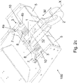
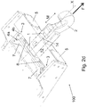
- FIGS 2a - 2d are schematic views of a detail of an arrangement in partial cross-section.
- the arrangement 100 has been arranged to a mine machine 6, in close proximity of a radiator of a cooler arrangement 15 of the mine machine.
- the proximity to the radiator is not necessary, i.e. the function of the arrangement 100 is not dependent on the radiator.
- the towing element 2 comprises a hook. In some another embodiments, such as shown in Figures, the towing element is other type of element, such as a loop.
- the hydraulic actuator 3 comprises a hydraulic cylinder that is arranged at least substantially parallel to a moving direction M of the body part 1.
- the hydraulic actuator is arranged to get shorter along with towing force affecting to the towing element 2.
- the hydraulic cylinder is connected to the hydraulic circuit of the braking system of the mine machine 6 so that hydraulic fluid may flow from the hydraulic cylinder to said hydraulic circuit and vice versa.
- the connection may comprise hydraulic hoses, couplings etc.
- a piston side chamber i.e. side opposite to a chamber of piston rod side, of the hydraulic cylinder is connected to the hydraulic circuit of the braking system of the mine machine 6.
- Volume of the piston side chamber is larger because the volume is not limited by piston rod, and thus a large volume flow of pressure fluid out from the cylinder is achieved compared to outer dimensions of the cylinder. This makes it possible to use smaller cylinders in the arrangement 100.
- hydraulic actuators 3 there are at least two hydraulic actuators 3 arranged parallel in the arrangement 100, as in the embodiment shown in the Figures.
- the hydraulic actuators 3 may be arranged symmetrically in relation to a longitudinal axis X of the arrangement.
- the hydraulic actuators 3, or just one hydraulic actuator 3 is/are arranged asymmetrically in relation to a longitudinal axis X of the arrangement.
- First part 4a of the hydraulic actuator is attached to extension 7 of the body part 1.
- the extension 7 extends sideward in relation to the longitudinal axis X of the arrangement.
- the shown embodiment has two extensions 7 directed opposite directions.
- the attachment of the first part 4a may be realized some other structure, too, provided that the structure may transfer movements of the body part 1 to the first part.
- the extension may extend in any direction in relation to the longitudinal axis X of the arrangement.
- Second part 4b of the hydraulic actuator is attached to a support element 5.
- the support element 5 is attached to a frame part 12 of the mining machine by attaching means 11.
- Said attaching means may comprise screws, bolts, nuts or any fixation means known per se.
- the support element 5 is attached to a frame part 12 by a welded joint.
- the hydraulic actuator 3 comprises connectors 10 for connecting said actuator to a hydraulic circuit of a braking system of the mine machine 6.
- the hydraulic pressure created in the hydraulic actuator 3 due to the towing force affecting to the towing element 2 is arranged to release brakes of the mine machine 6.
- the arrangement 100 comprises just one hydraulic actuator only.
- the hydraulic actuator may be arranged e.g. inside the body part 1.
- the arrangement comprises more than two, for instance three or four, hydraulic actuators.
- the arrangement 100 comprises at least one returning element 8 that is arranged to return the body part 1 in its initial position in relation to the support element 5 when towing element 2 is released from the towing force.
- the arrangement 100 comprises two coil spring elements as the returning element 8.
- the returning element 8 comprises another type of mechanical spring, such as a leaf spring.
- the returning element 8 comprises a gas spring.
- the spring elements are arranged separately from the hydraulic actuators 3.
- the returning element 8 is integrated in the hydraulic actuator 3, either inside or outside thereof.
- the chamber of piston rod side of the hydraulic cylinder is filled with gas, for example nitrogen. Said gas expands and its pressure drops when the cylinder is compressed. As the towing element 2 is released from the towing force, said gas in underpressurized state helps the cylinder to return in its initial length.
- the hydraulic cylinder comprises a spring, such as a coil spring, arranged inside the cylinder or around the exterior of the cylinder.
- the arrangement 100 comprises a stopper arrangement 9 that transfers at least a part of towing forces from the body part 1 to the frame of the machine.
- the stopper arrangement 9 comprises an oblong through hole 14 in the body part 1, and a pin 13 arranged movably in the hole 14.
- the pin 13 is attached to the frame of the machine and arranged perpendicular to the moving direction M of the body part 1.
- the pin abuts against the hole 14 when the machine 6 is being towed.
- the body part 1 comprises an abutting surface or extension (not shown) that abuts against a frame part of the mine machine and thus transfers towing forces in the frame of the mine machine.
- Figure 2c is showing the arrangement 100 in its rest state, i.e. when there is no towing force affecting to the towing element 2.
- the hydraulic actuators 3 and the returning elements 8 are in their extended states and the body part 1 retracted inside the structure of the mine machine. If the mine machine 6, for some reason, has lost vehicle power or hydraulic fluid pressure, an automatic fail-safe braking is on and brakes of the machine prevent the machine from moving.
- Figure 2d is showing the arrangement 100 when a towing force F is affecting to the towing element 2.
- the extensions 7 are pressing the hydraulic actuators 3 that thus get shorter.
- hydraulic fluid flows from the hydraulic actuators 3 to the hydraulic circuit of the braking system of the mine machine 6 releasing brakes thereof, allowing towing the mine machine 6.
- the brakes of the mine machine go on, and the mine machine does not move unintentionally.
- the brakes go on when the towing element 2 and the body part 1 have retracted completely.
- the brakes go on when the towing element 2 and the body part 1 have retracted a predetermined length towards the rest state.
- Said predetermined length may be, e.g. 50 mm - 200 mm, for instance 80 mm, 100 mm, or 150 mm.
Abstract
Description
- The invention relates to a towing arrangement for a mine machine.
- The invention further relates to a mine machine.
- For safety reasons, many mine machines use hydraulically-released brake systems to provide automatic fail-safe braking on loss of vehicle power or hydraulic fluid pressure. Such brakes prevent a disabled machine from easily being towed. In order to tow the disabled machine easily, it is known to provide towing or retrieval hook of such a mine machine with a releasing arrangement that releases brake when the machine is towed from the hook, thus permitting the towing of the disabled mine machine.
- However, existing releasing arrangements are often large and their structure susceptible to be damaged in harsh environment of mines.
- Viewed from a first aspect, there can be provided a towing arrangement for a mine machine, comprising
- a body part,
- a towing element for allowing a towing tool to be connected to the towing arrangement,
- the towing element being attached to the body part,
- a hydraulic actuator,
- a first part of the hydraulic actuator attached to the body part, and
- a second part of the hydraulic actuator attachable to a support element,
- the support element, when the towing arrangement being attached to the mine machine, being fixed to said mine machine,
- the body part being arranged movable in relation to the support element,
- the body part being arranged to move in relation to the support element when a towing force is affecting to the towing element, and
- the hydraulic actuator is arranged to get shorter along with said towing force affecting to the towing element.
- Thereby a towing arrangement for a mine machine being compact in size and easy to arrange, even to retrofit, in a mine machine may be achieved.
- Viewed from a further aspect, there can be provided a mine machine comprising the towing arrangement mentioned above.
- Thereby a mine machine the towing arrangement of which is compact in size and well protected may be achieved.
- The arrangement and the method are characterised by what is stated in the independent claims. Some other embodiments are characterised by what is stated in the other claims. Inventive embodiments are also disclosed in the specification and drawings of this patent application. The inventive content of the patent application may also be defined in other ways than defined in the following claims. The inventive content may also be formed of several separate inventions, especially if the invention is examined in the light of expressed or implicit sub-tasks or in view of obtained benefits or benefit groups. Some of the definitions contained in the following claims may then be unnecessary in view of the separate inventive ideas. Features of the different embodiments of the invention may, within the scope of the basic inventive idea, be applied to other embodiments.
- In one embodiment, the towing element comprises a hook. An advantage is that the hook is easy and fast to use in towing.
- In one embodiment, the
hydraulic actuator 3 comprises a hydraulic cylinder. An advantage is that hydraulic cylinders have a simple structure and they are straightforwardly adaptable to the arrangement. - In one embodiment, the arrangement comprises at least two hydraulic actuators. An advantage is that smaller actuators may be used without compromising volume flow of hydraulic fluid created by the arrangement and fed in the braking system of the mine machine.
- In one embodiment, the arrangement comprises at least two hydraulic actuators being arranged symmetrically in relation to a longitudinal axis of the arrangement. An advantage is that a stable movement of the frame may be achieved.
- In one embodiment, the body part comprises at least one extension arranged to extend sideward in relation to the longitudinal axis of the arrangement, the first part of the hydraulic actuator being attached to the extension, and the extension being arranged to forward the movement of the towing element in the hydraulic actuator. An advantage is that the hydraulic actuator may be arranged laterally in relation to the frame, and thus the length of the arrangement reduced.
- In one embodiment, the arrangement comprises a returning element arranged to return the body part in its initial position in relation to the support element when towing element is released from the towing force. An advantage is that the body part may return quickly to the original position as before starting the towing action and the brakes of the mine machine go on.
- In one embodiment, the returning element comprises at least one spring element. An advantage is that spring elements are simple and cost-effective mechanical parts.
- In one embodiment, the arrangement comprises a stopper arrangement for transferring towing forces from the body part to the frame of the machine. An advantage is that the forces do not focus on the hydraulic actuator and/or the returning element.
- In one embodiment, the hydraulic actuator is arranged at least substantially parallel to a moving direction of the body part. An advantage is that the movement of the body part is transferred directly to the actuator.
- In one embodiment, the hydraulic actuator comprises connectors for connection to a hydraulic circuit of a braking system of the mine machine, and wherein hydraulic pressure created in the hydraulic actuator due to the towing force affecting to the towing element is arranged to release brakes of the mine machine. An advantage is that the arrangement controls the braking system in a simple way.
- In one embodiment, the support element comprises attaching means for attachment the support element to the mine machine. An advantage is that the support element may be manufactured separate from the structure of the mine machine.
- In one embodiment, the arrangement is formed into a structural module retrofittable in a mine machine. An advantage is that mine machines without the towing arrangement may be equipped with the arrangement.
- In one embodiment, a frame part of the mine machine is arranged to perform as the support element. An advantage is that the structure of the towing arrangement may be simplified.
- Some embodiments illustrating the present disclosure are described in more detail in the attached drawings, in which
-
Figure 1 is a schematic view of a part of a mine machine, and -
Figures 2a - 2d are schematic views of a detail of an arrangement in partial cross-section. - In the figures, some embodiments are shown simplified for the sake of clarity. Similar parts are marked with the same reference numbers in the figures.
-
Figure 1 is a schematic view of a part of a mine machine. - The
mine machine 6 may be e.g. a wheel loader. However, themine machine 6 may be any type of a mining vehicle or a construction vehicle. Themine machine 6 may be provided with one or more working devices for executing designed work tasks at the work site. Thus, themine machine 6 may also be a transport vehicle or dumper, a rock drilling rig, a bolting or reinforcing machine or a measuring machine, for example. - The
mine machine 6 comprises atowing arrangement 100 for towing the machine. The towingarrangement 100 comprises a body part (not shown inFigure 1 ) and atowing element 2 for allowing a towing tool to be connected to thetowing arrangement 100 and thereby to themine machine 6. - The towing
arrangement 100 is further provided with a hydraulic actuator (not shown InFigure 1 ) that comprises a first part attached to the body part, and a second part attachable to asupport element 5. - The
support element 5 is fixed to themine machine 6. In an embodiment, aframe part 12 of themine machine 6 is arranged to perform as saidsupport element 5. In another embodiment, thesupport element 5 is an additional element, i.e. not a part of the frame of themine machine 6, that comprises attaching means by which the support element can be attached to themine machine 6. The attaching means may comprise e.g. bolts or screws and corresponding holes. Thus, thearrangement 100 may be a structural module that is retrofittable in mine machines. - The body part is movable in relation to the
support element 5 in moving directions M so that the body part moves in relation to thesupport element 5 when a towing force is affecting to thetowing element 2. - The structure and the features of the
towing arrangement 100 are described more detailed in connection with the following figures. -
Figures 2a - 2d are schematic views of a detail of an arrangement in partial cross-section. Thearrangement 100 has been arranged to amine machine 6, in close proximity of a radiator of acooler arrangement 15 of the mine machine. However, the proximity to the radiator is not necessary, i.e. the function of thearrangement 100 is not dependent on the radiator. - In some embodiments, such as shown in Figures, the towing
element 2 comprises a hook. In some another embodiments, the towing element is other type of element, such as a loop. - In an embodiment, the
hydraulic actuator 3 comprises a hydraulic cylinder that is arranged at least substantially parallel to a moving direction M of thebody part 1. The hydraulic actuator is arranged to get shorter along with towing force affecting to thetowing element 2. - According to an aspect of the invention, the hydraulic cylinder is connected to the hydraulic circuit of the braking system of the
mine machine 6 so that hydraulic fluid may flow from the hydraulic cylinder to said hydraulic circuit and vice versa. The connection may comprise hydraulic hoses, couplings etc. - In an embodiment, a piston side chamber, i.e. side opposite to a chamber of piston rod side, of the hydraulic cylinder is connected to the hydraulic circuit of the braking system of the
mine machine 6. Volume of the piston side chamber is larger because the volume is not limited by piston rod, and thus a large volume flow of pressure fluid out from the cylinder is achieved compared to outer dimensions of the cylinder. This makes it possible to use smaller cylinders in thearrangement 100. - In an embodiment, there are at least two
hydraulic actuators 3 arranged parallel in thearrangement 100, as in the embodiment shown in the Figures. Thehydraulic actuators 3 may be arranged symmetrically in relation to a longitudinal axis X of the arrangement. In another embodiment, thehydraulic actuators 3, or just onehydraulic actuator 3, is/are arranged asymmetrically in relation to a longitudinal axis X of the arrangement. -
First part 4a of the hydraulic actuator is attached toextension 7 of thebody part 1. Theextension 7 extends sideward in relation to the longitudinal axis X of the arrangement. The shown embodiment has twoextensions 7 directed opposite directions. However, the attachment of thefirst part 4a may be realized some other structure, too, provided that the structure may transfer movements of thebody part 1 to the first part. For instance, the extension may extend in any direction in relation to the longitudinal axis X of the arrangement. -
Second part 4b of the hydraulic actuator is attached to asupport element 5. In the embodiment shown inFigures 2a -2d , thesupport element 5 is attached to aframe part 12 of the mining machine by attachingmeans 11. Said attaching means may comprise screws, bolts, nuts or any fixation means known per se. In an embodiment, thesupport element 5 is attached to aframe part 12 by a welded joint. - The
hydraulic actuator 3 comprisesconnectors 10 for connecting said actuator to a hydraulic circuit of a braking system of themine machine 6. The hydraulic pressure created in thehydraulic actuator 3 due to the towing force affecting to thetowing element 2 is arranged to release brakes of themine machine 6. - In an embodiment, the
arrangement 100 comprises just one hydraulic actuator only. In this embodiment, the hydraulic actuator may be arranged e.g. inside thebody part 1. - In still another embodiments, the arrangement comprises more than two, for instance three or four, hydraulic actuators.
- In an embodiment, the
arrangement 100 comprises at least one returningelement 8 that is arranged to return thebody part 1 in its initial position in relation to thesupport element 5 when towingelement 2 is released from the towing force. In the embodiments shown in Figures, thearrangement 100 comprises two coil spring elements as the returningelement 8. In another embodiments, the returningelement 8 comprises another type of mechanical spring, such as a leaf spring. In still another embodiment, the returningelement 8 comprises a gas spring. - The spring elements are arranged separately from the
hydraulic actuators 3. In another embodiment, the returningelement 8 is integrated in thehydraulic actuator 3, either inside or outside thereof. In an embodiment, the chamber of piston rod side of the hydraulic cylinder is filled with gas, for example nitrogen. Said gas expands and its pressure drops when the cylinder is compressed. As thetowing element 2 is released from the towing force, said gas in underpressurized state helps the cylinder to return in its initial length. In still another embodiment, the hydraulic cylinder comprises a spring, such as a coil spring, arranged inside the cylinder or around the exterior of the cylinder. - In an embodiment, the
arrangement 100 comprises a stopper arrangement 9 that transfers at least a part of towing forces from thebody part 1 to the frame of the machine. In the embodiment shown in Figures, the stopper arrangement 9 comprises an oblong throughhole 14 in thebody part 1, and apin 13 arranged movably in thehole 14. Thepin 13 is attached to the frame of the machine and arranged perpendicular to the moving direction M of thebody part 1. The pin abuts against thehole 14 when themachine 6 is being towed. In another embodiment, thebody part 1 comprises an abutting surface or extension (not shown) that abuts against a frame part of the mine machine and thus transfers towing forces in the frame of the mine machine. -
Figure 2c is showing thearrangement 100 in its rest state, i.e. when there is no towing force affecting to thetowing element 2. Thehydraulic actuators 3 and the returningelements 8 are in their extended states and thebody part 1 retracted inside the structure of the mine machine. If themine machine 6, for some reason, has lost vehicle power or hydraulic fluid pressure, an automatic fail-safe braking is on and brakes of the machine prevent the machine from moving. -
Figure 2d is showing thearrangement 100 when a towing force F is affecting to thetowing element 2. Now thebody part 1 is pulled out from the structure of the mine machine. Theextensions 7 are pressing thehydraulic actuators 3 that thus get shorter. As a result, hydraulic fluid flows from thehydraulic actuators 3 to the hydraulic circuit of the braking system of themine machine 6 releasing brakes thereof, allowing towing themine machine 6. - As soon as the towing force F is withdrawn, the returning
elements 8 force thearrangement 100 to return in the rest state shown inFigure 2c . - Following this, the brakes of the mine machine go on, and the mine machine does not move unintentionally. In an embodiment, the brakes go on when the towing
element 2 and thebody part 1 have retracted completely. In another embodiment, the brakes go on when the towingelement 2 and thebody part 1 have retracted a predetermined length towards the rest state. In other words, the brakes go on prior to thetowing element 2 and thebody part 1 have reached the rest state. Said predetermined length may be, e.g. 50 mm - 200 mm, for instance 80 mm, 100 mm, or 150 mm.
The invention is not limited solely to the embodiments described above, but instead many variations are possible within the scope of the inventive concept defined by the claims below. Within the scope of the inventive concept the attributes of different embodiments and applications can be used in conjunction with or replace the attributes of another embodiment or application. - The drawings and the related description are only intended to illustrate the idea of the invention. The invention may vary in detail within the scope of the inventive idea defined in the following claims.
-
- 1
- body part
- 2
- towing element
- 3
- hydraulic actuator
- 4a, b
- parts of hydraulic actuator
- 5
- support element
- 6
- mine machine
- 7
- extension
- 8
- returning element
- 9
- stopper arrangement
- 10
- connector
- 11
- attaching means
- 12
- frame part of mining machine
- 13
- pin
- 14
- through hole
- 15
- cooler arrangement
- 100
- towing arrangement
- F
- towing force
- M
- moving direction
- X
- longitudinal axis
Claims (15)
- A towing arrangement for a mine machine, comprising- a body part (1),- a towing element (2) for allowing a towing tool to be connected to the towing arrangement (100),- the towing element (2) being attached to the body part (1),- a hydraulic actuator (3),- a first part (4a) of the hydraulic actuator (3) attached to the body part (1), and- a second part (4b) of the hydraulic actuator (3) attachable to a support element (5),- the support element (5), when the towing arrangement being attached to the mine machine (6), being fixed to said mine machine (6),- the body part (1) being arranged movable in relation to the support element (5),- the body part (1) being arranged to move in relation to the support element (5) when a towing force is affecting to the towing element (2), and- the hydraulic actuator (3) is arranged to get shorter along with said towing force affecting to the towing element (2).
- The arrangement as claimed in claim 1, wherein the towing element (2) comprises a hook.
- The arrangement as claimed in claims 1 or 2, wherein the hydraulic actuator (3) comprises a hydraulic cylinder.
- The arrangement as claimed in any of the preceding claims, comprising at least two hydraulic actuators (3).
- The arrangement as claimed in claim 4, wherein the hydraulic actuators (3) are arranged symmetrically in relation to a longitudinal axis (X) of the arrangement.
- The arrangement as claimed in claims 4 or 5, wherein the body part (1) comprises at least one extension (7) arranged to extend sideward in relation to the longitudinal axis (X) of the arrangement,- the first part (4a) of the hydraulic actuator being attached to the extension (7), and- the extension (7) being arranged to forward the movement of the towing element (2) in the hydraulic actuator (3).
- The arrangement as claimed in any of the preceding claims, comprising a returning element (8) arranged to return the body part (1) in its initial position in relation to the support element (5) when towing element (2) is released from the towing force.
- The arrangement as claimed in claim 7, wherein the returning element (8) comprises at least one spring element.
- The arrangement as claimed in any of the preceding claims, comprising a stopper arrangement (9) for transferring towing forces from the body part (1) to the frame of the machine.
- The arrangement as claimed in any of the preceding claims, wherein the hydraulic actuator (3) is arranged at least substantially parallel to a moving direction (M) of the body part (1).
- The arrangement as claimed in any of the preceding claims, wherein the hydraulic actuator (3) comprises connectors (10) for connection to a hydraulic circuit of a braking system of the mine machine (6), and wherein- hydraulic pressure created in the hydraulic actuator (3) due to the towing force affecting to the towing element (2) is arranged to release brakes of the mine machine (6).
- The arrangement as claimed in any of the preceding claims, wherein the support element (5) comprises attaching means (11) for attachment the support element to the mine machine (6).
- The arrangement as claimed in any of the preceding claims, being formed into a structural module retrofittable in a mine machine (6).
- A mine machine, comprising the arrangement as claimed in any of the preceding claims.
- The mine machine as claimed in claim 14, wherein a frame part (12) of the mine machine is arranged to perform as the support element (5).
Priority Applications (9)
| Application Number | Priority Date | Filing Date | Title |
|---|---|---|---|
| PL19172195.0T PL3733432T3 (en) | 2019-05-02 | 2019-05-02 | Towing arrangement and mine machine |
| EP19172195.0A EP3733432B1 (en) | 2019-05-02 | 2019-05-02 | Towing arrangement and mine machine |
| FIEP19172195.0T FI3733432T3 (en) | 2019-05-02 | 2019-05-02 | Towing arrangement and mine machine |
| EA202192494A EA202192494A1 (en) | 2019-05-02 | 2020-04-29 | TOWING DEVICE AND MINING MACHINE |
| PCT/EP2020/061879 WO2020221798A1 (en) | 2019-05-02 | 2020-04-29 | Towing arrangement and mine machine |
| PE2021001734A PE20212128A1 (en) | 2019-05-02 | 2020-04-29 | ARRANGEMENT OF TOWING AND MINING MACHINE |
| CN202080030471.0A CN113710509B (en) | 2019-05-02 | 2020-04-29 | Traction device and mining machine |
| MX2021013403A MX2021013403A (en) | 2019-05-02 | 2020-04-29 | Towing arrangement and mine machine. |
| CL2021002825A CL2021002825A1 (en) | 2019-05-02 | 2021-10-27 | Towing arrangement and mining machine. |
Applications Claiming Priority (1)
| Application Number | Priority Date | Filing Date | Title |
|---|---|---|---|
| EP19172195.0A EP3733432B1 (en) | 2019-05-02 | 2019-05-02 | Towing arrangement and mine machine |
Publications (2)
| Publication Number | Publication Date |
|---|---|
| EP3733432A1 true EP3733432A1 (en) | 2020-11-04 |
| EP3733432B1 EP3733432B1 (en) | 2023-07-12 |
Family
ID=66379742
Family Applications (1)
| Application Number | Title | Priority Date | Filing Date |
|---|---|---|---|
| EP19172195.0A Active EP3733432B1 (en) | 2019-05-02 | 2019-05-02 | Towing arrangement and mine machine |
Country Status (9)
| Country | Link |
|---|---|
| EP (1) | EP3733432B1 (en) |
| CN (1) | CN113710509B (en) |
| CL (1) | CL2021002825A1 (en) |
| EA (1) | EA202192494A1 (en) |
| FI (1) | FI3733432T3 (en) |
| MX (1) | MX2021013403A (en) |
| PE (1) | PE20212128A1 (en) |
| PL (1) | PL3733432T3 (en) |
| WO (1) | WO2020221798A1 (en) |
Cited By (2)
| Publication number | Priority date | Publication date | Assignee | Title |
|---|---|---|---|---|
| CN113335398A (en) * | 2021-08-06 | 2021-09-03 | 沛县迅驰专用车辆制造有限公司 | Adjustable saddle type traction connector and trailer thereof |
| EP4194234A1 (en) * | 2021-12-08 | 2023-06-14 | Sandvik Mining and Construction Oy | Towing arrangement of a battery-powered mining machine and a battery-powered mining machine |
Citations (4)
| Publication number | Priority date | Publication date | Assignee | Title |
|---|---|---|---|---|
| US20040066089A1 (en) * | 2002-10-02 | 2004-04-08 | Roll Michael J. | Surge brake actuator |
| CN103434351A (en) * | 2013-08-20 | 2013-12-11 | 张晓荣 | Spring tow hook |
| WO2015073960A1 (en) * | 2013-11-18 | 2015-05-21 | Teleswivel, Llc | Intelligent hitch apparatus for vehicles |
| EP3415398A1 (en) * | 2017-06-15 | 2018-12-19 | Sandvik Mining and Construction Oy | Towing hook |
Family Cites Families (7)
| Publication number | Priority date | Publication date | Assignee | Title |
|---|---|---|---|---|
| GB1224491A (en) * | 1968-01-19 | 1971-03-10 | Ibbett Engineering Company Ltd | Trailer towing assembly |
| GB1367557A (en) * | 1972-08-04 | 1974-09-18 | Beach J M | Draft device |
| US4840256A (en) * | 1988-05-05 | 1989-06-20 | Webb James E | Surge brake apparatus for gooseneck trailers |
| RU2145011C1 (en) * | 1998-10-13 | 2000-01-27 | Цыпцын Валерий Иванович | Hydraulic shock absorber for rigid towing gear |
| US8327982B2 (en) * | 2002-04-30 | 2012-12-11 | Titan International, Inc. | Actuator/coupler for towed and towing vehicle combination |
| EP2357114B1 (en) * | 2006-05-22 | 2014-04-02 | Continental Teves AG & Co. oHG | Hydraulic trailer brake system |
| CN102602255A (en) * | 2011-03-07 | 2012-07-25 | 绿友机械集团股份有限公司 | Multifunctional tow bar device for trailer |
-
2019
- 2019-05-02 FI FIEP19172195.0T patent/FI3733432T3/en active
- 2019-05-02 EP EP19172195.0A patent/EP3733432B1/en active Active
- 2019-05-02 PL PL19172195.0T patent/PL3733432T3/en unknown
-
2020
- 2020-04-29 EA EA202192494A patent/EA202192494A1/en unknown
- 2020-04-29 WO PCT/EP2020/061879 patent/WO2020221798A1/en active Application Filing
- 2020-04-29 PE PE2021001734A patent/PE20212128A1/en unknown
- 2020-04-29 CN CN202080030471.0A patent/CN113710509B/en active Active
- 2020-04-29 MX MX2021013403A patent/MX2021013403A/en unknown
-
2021
- 2021-10-27 CL CL2021002825A patent/CL2021002825A1/en unknown
Patent Citations (4)
| Publication number | Priority date | Publication date | Assignee | Title |
|---|---|---|---|---|
| US20040066089A1 (en) * | 2002-10-02 | 2004-04-08 | Roll Michael J. | Surge brake actuator |
| CN103434351A (en) * | 2013-08-20 | 2013-12-11 | 张晓荣 | Spring tow hook |
| WO2015073960A1 (en) * | 2013-11-18 | 2015-05-21 | Teleswivel, Llc | Intelligent hitch apparatus for vehicles |
| EP3415398A1 (en) * | 2017-06-15 | 2018-12-19 | Sandvik Mining and Construction Oy | Towing hook |
Cited By (3)
| Publication number | Priority date | Publication date | Assignee | Title |
|---|---|---|---|---|
| CN113335398A (en) * | 2021-08-06 | 2021-09-03 | 沛县迅驰专用车辆制造有限公司 | Adjustable saddle type traction connector and trailer thereof |
| EP4194234A1 (en) * | 2021-12-08 | 2023-06-14 | Sandvik Mining and Construction Oy | Towing arrangement of a battery-powered mining machine and a battery-powered mining machine |
| WO2023104357A1 (en) * | 2021-12-08 | 2023-06-15 | Sandvik Mining And Construction Oy | Towing arrangement of a battery-powered mining machine and a battery-powered mining machine |
Also Published As
| Publication number | Publication date |
|---|---|
| FI3733432T3 (en) | 2023-08-16 |
| EP3733432B1 (en) | 2023-07-12 |
| PE20212128A1 (en) | 2021-11-05 |
| MX2021013403A (en) | 2021-11-25 |
| CN113710509B (en) | 2024-01-02 |
| WO2020221798A1 (en) | 2020-11-05 |
| CL2021002825A1 (en) | 2022-06-24 |
| CN113710509A (en) | 2021-11-26 |
| EA202192494A1 (en) | 2022-03-31 |
| PL3733432T3 (en) | 2023-09-25 |
Similar Documents
| Publication | Publication Date | Title |
|---|---|---|
| EP3733432B1 (en) | Towing arrangement and mine machine | |
| US7464967B2 (en) | Hydraulic quick coupling | |
| US7121185B2 (en) | Hydraulic cylinder having a snubbing valve | |
| US20140062178A1 (en) | Method and system for releasing parking brake of an anchored machine and a machine with the same | |
| US10479658B2 (en) | Telescopic device of single-cylinder latch type and crane | |
| CN101817480A (en) | Stop and bolt clamping unit | |
| WO2017079792A1 (en) | A piston and cylinder system | |
| CN110709306B (en) | Towing hook | |
| WO2021209445A1 (en) | Towing arrangement and mobile work machine | |
| KR100861487B1 (en) | Attachment coupler for heavy machinery having an improved automatic safety function | |
| CN201647917U (en) | Multistage hydraulic telescopic rod mechanism capable of being self-locked | |
| US9738498B2 (en) | Telescopic boom extension device | |
| CN210034043U (en) | Energy storage type locking mechanism | |
| EA041554B1 (en) | TOWING DEVICE AND MINING MACHINE | |
| JP2012512088A (en) | Locking device for variable gauge chassis | |
| EP2501605B1 (en) | Apparatus for a variable gauge undercarriage | |
| RU2772401C1 (en) | Recuperative spring-hydraulic coupling device of a single-acting road train | |
| CN217354953U (en) | Trailer system matched with SHAR braking mode, engineering vehicle and underground scraper | |
| CN103086284B (en) | Self-steering telescopic arm device | |
| EP2455321B1 (en) | A method for damping oscillations and a crane provided with an oscillation damper | |
| EP2349817B1 (en) | Steering devices | |
| SE501152C2 (en) | Device for rapid coupling of tool to digging-loading machine - simultaneously connects hydraulic drive system to tool and comprises manoeuvring component for locking and-or retention of tool | |
| US20230313486A1 (en) | Control system for actuated pins | |
| CN105164346A (en) | Hydraulic actuator | |
| CA3180506A1 (en) | Compact actuated shear pin |
Legal Events
| Date | Code | Title | Description |
|---|---|---|---|
| PUAI | Public reference made under article 153(3) epc to a published international application that has entered the european phase |
Free format text: ORIGINAL CODE: 0009012 |
|
| STAA | Information on the status of an ep patent application or granted ep patent |
Free format text: STATUS: THE APPLICATION HAS BEEN PUBLISHED |
|
| AK | Designated contracting states |
Kind code of ref document: A1 Designated state(s): AL AT BE BG CH CY CZ DE DK EE ES FI FR GB GR HR HU IE IS IT LI LT LU LV MC MK MT NL NO PL PT RO RS SE SI SK SM TR |
|
| AX | Request for extension of the european patent |
Extension state: BA ME |
|
| STAA | Information on the status of an ep patent application or granted ep patent |
Free format text: STATUS: REQUEST FOR EXAMINATION WAS MADE |
|
| 17P | Request for examination filed |
Effective date: 20210504 |
|
| RBV | Designated contracting states (corrected) |
Designated state(s): AL AT BE BG CH CY CZ DE DK EE ES FI FR GB GR HR HU IE IS IT LI LT LU LV MC MK MT NL NO PL PT RO RS SE SI SK SM TR |
|
| GRAP | Despatch of communication of intention to grant a patent |
Free format text: ORIGINAL CODE: EPIDOSNIGR1 |
|
| STAA | Information on the status of an ep patent application or granted ep patent |
Free format text: STATUS: GRANT OF PATENT IS INTENDED |
|
| INTG | Intention to grant announced |
Effective date: 20230130 |
|
| GRAS | Grant fee paid |
Free format text: ORIGINAL CODE: EPIDOSNIGR3 |
|
| GRAA | (expected) grant |
Free format text: ORIGINAL CODE: 0009210 |
|
| STAA | Information on the status of an ep patent application or granted ep patent |
Free format text: STATUS: THE PATENT HAS BEEN GRANTED |
|
| AK | Designated contracting states |
Kind code of ref document: B1 Designated state(s): AL AT BE BG CH CY CZ DE DK EE ES FI FR GB GR HR HU IE IS IT LI LT LU LV MC MK MT NL NO PL PT RO RS SE SI SK SM TR |
|
| P01 | Opt-out of the competence of the unified patent court (upc) registered |
Effective date: 20230603 |
|
| REG | Reference to a national code |
Ref country code: CH Ref legal event code: EP |
|
| REG | Reference to a national code |
Ref country code: DE Ref legal event code: R096 Ref document number: 602019032414 Country of ref document: DE |
|
| REG | Reference to a national code |
Ref country code: IE Ref legal event code: FG4D |
|
| REG | Reference to a national code |
Ref country code: SE Ref legal event code: TRGR |
|
| REG | Reference to a national code |
Ref country code: LT Ref legal event code: MG9D |
|
| REG | Reference to a national code |
Ref country code: NL Ref legal event code: MP Effective date: 20230712 |
|
| REG | Reference to a national code |
Ref country code: AT Ref legal event code: MK05 Ref document number: 1586763 Country of ref document: AT Kind code of ref document: T Effective date: 20230712 |
|
| PG25 | Lapsed in a contracting state [announced via postgrant information from national office to epo] |
Ref country code: NL Free format text: LAPSE BECAUSE OF FAILURE TO SUBMIT A TRANSLATION OF THE DESCRIPTION OR TO PAY THE FEE WITHIN THE PRESCRIBED TIME-LIMIT Effective date: 20230712 |
|
| PG25 | Lapsed in a contracting state [announced via postgrant information from national office to epo] |
Ref country code: GR Free format text: LAPSE BECAUSE OF FAILURE TO SUBMIT A TRANSLATION OF THE DESCRIPTION OR TO PAY THE FEE WITHIN THE PRESCRIBED TIME-LIMIT Effective date: 20231013 |
|
| PG25 | Lapsed in a contracting state [announced via postgrant information from national office to epo] |
Ref country code: ES Free format text: LAPSE BECAUSE OF FAILURE TO SUBMIT A TRANSLATION OF THE DESCRIPTION OR TO PAY THE FEE WITHIN THE PRESCRIBED TIME-LIMIT Effective date: 20230712 |
|
| PG25 | Lapsed in a contracting state [announced via postgrant information from national office to epo] |
Ref country code: IS Free format text: LAPSE BECAUSE OF FAILURE TO SUBMIT A TRANSLATION OF THE DESCRIPTION OR TO PAY THE FEE WITHIN THE PRESCRIBED TIME-LIMIT Effective date: 20231112 |
|
| PG25 | Lapsed in a contracting state [announced via postgrant information from national office to epo] |
Ref country code: RS Free format text: LAPSE BECAUSE OF FAILURE TO SUBMIT A TRANSLATION OF THE DESCRIPTION OR TO PAY THE FEE WITHIN THE PRESCRIBED TIME-LIMIT Effective date: 20230712 Ref country code: PT Free format text: LAPSE BECAUSE OF FAILURE TO SUBMIT A TRANSLATION OF THE DESCRIPTION OR TO PAY THE FEE WITHIN THE PRESCRIBED TIME-LIMIT Effective date: 20231113 Ref country code: NO Free format text: LAPSE BECAUSE OF FAILURE TO SUBMIT A TRANSLATION OF THE DESCRIPTION OR TO PAY THE FEE WITHIN THE PRESCRIBED TIME-LIMIT Effective date: 20231012 Ref country code: LV Free format text: LAPSE BECAUSE OF FAILURE TO SUBMIT A TRANSLATION OF THE DESCRIPTION OR TO PAY THE FEE WITHIN THE PRESCRIBED TIME-LIMIT Effective date: 20230712 Ref country code: LT Free format text: LAPSE BECAUSE OF FAILURE TO SUBMIT A TRANSLATION OF THE DESCRIPTION OR TO PAY THE FEE WITHIN THE PRESCRIBED TIME-LIMIT Effective date: 20230712 Ref country code: IS Free format text: LAPSE BECAUSE OF FAILURE TO SUBMIT A TRANSLATION OF THE DESCRIPTION OR TO PAY THE FEE WITHIN THE PRESCRIBED TIME-LIMIT Effective date: 20231112 Ref country code: HR Free format text: LAPSE BECAUSE OF FAILURE TO SUBMIT A TRANSLATION OF THE DESCRIPTION OR TO PAY THE FEE WITHIN THE PRESCRIBED TIME-LIMIT Effective date: 20230712 Ref country code: GR Free format text: LAPSE BECAUSE OF FAILURE TO SUBMIT A TRANSLATION OF THE DESCRIPTION OR TO PAY THE FEE WITHIN THE PRESCRIBED TIME-LIMIT Effective date: 20231013 Ref country code: ES Free format text: LAPSE BECAUSE OF FAILURE TO SUBMIT A TRANSLATION OF THE DESCRIPTION OR TO PAY THE FEE WITHIN THE PRESCRIBED TIME-LIMIT Effective date: 20230712 Ref country code: AT Free format text: LAPSE BECAUSE OF FAILURE TO SUBMIT A TRANSLATION OF THE DESCRIPTION OR TO PAY THE FEE WITHIN THE PRESCRIBED TIME-LIMIT Effective date: 20230712 |
|
| PG25 | Lapsed in a contracting state [announced via postgrant information from national office to epo] |
Ref country code: SM Free format text: LAPSE BECAUSE OF FAILURE TO SUBMIT A TRANSLATION OF THE DESCRIPTION OR TO PAY THE FEE WITHIN THE PRESCRIBED TIME-LIMIT Effective date: 20230712 Ref country code: RO Free format text: LAPSE BECAUSE OF FAILURE TO SUBMIT A TRANSLATION OF THE DESCRIPTION OR TO PAY THE FEE WITHIN THE PRESCRIBED TIME-LIMIT Effective date: 20230712 Ref country code: EE Free format text: LAPSE BECAUSE OF FAILURE TO SUBMIT A TRANSLATION OF THE DESCRIPTION OR TO PAY THE FEE WITHIN THE PRESCRIBED TIME-LIMIT Effective date: 20230712 Ref country code: DK Free format text: LAPSE BECAUSE OF FAILURE TO SUBMIT A TRANSLATION OF THE DESCRIPTION OR TO PAY THE FEE WITHIN THE PRESCRIBED TIME-LIMIT Effective date: 20230712 Ref country code: SK Free format text: LAPSE BECAUSE OF FAILURE TO SUBMIT A TRANSLATION OF THE DESCRIPTION OR TO PAY THE FEE WITHIN THE PRESCRIBED TIME-LIMIT Effective date: 20230712 |