EP3733040A1 - Water-transporting household device - Google Patents
Water-transporting household device Download PDFInfo
- Publication number
- EP3733040A1 EP3733040A1 EP20169290.2A EP20169290A EP3733040A1 EP 3733040 A1 EP3733040 A1 EP 3733040A1 EP 20169290 A EP20169290 A EP 20169290A EP 3733040 A1 EP3733040 A1 EP 3733040A1
- Authority
- EP
- European Patent Office
- Prior art keywords
- sump
- pump
- outlet
- impeller
- water
- Prior art date
- Legal status (The legal status is an assumption and is not a legal conclusion. Google has not performed a legal analysis and makes no representation as to the accuracy of the status listed.)
- Withdrawn
Links
Images


Classifications
-
- A—HUMAN NECESSITIES
- A47—FURNITURE; DOMESTIC ARTICLES OR APPLIANCES; COFFEE MILLS; SPICE MILLS; SUCTION CLEANERS IN GENERAL
- A47L—DOMESTIC WASHING OR CLEANING; SUCTION CLEANERS IN GENERAL
- A47L15/00—Washing or rinsing machines for crockery or tableware
- A47L15/42—Details
- A47L15/4214—Water supply, recirculation or discharge arrangements; Devices therefor
- A47L15/4225—Arrangements or adaption of recirculation or discharge pumps
-
- D—TEXTILES; PAPER
- D06—TREATMENT OF TEXTILES OR THE LIKE; LAUNDERING; FLEXIBLE MATERIALS NOT OTHERWISE PROVIDED FOR
- D06F—LAUNDERING, DRYING, IRONING, PRESSING OR FOLDING TEXTILE ARTICLES
- D06F39/00—Details of washing machines not specific to a single type of machines covered by groups D06F9/00 - D06F27/00
- D06F39/08—Liquid supply or discharge arrangements
- D06F39/083—Liquid discharge or recirculation arrangements
- D06F39/085—Arrangements or adaptations of pumps
-
- D—TEXTILES; PAPER
- D06—TREATMENT OF TEXTILES OR THE LIKE; LAUNDERING; FLEXIBLE MATERIALS NOT OTHERWISE PROVIDED FOR
- D06F—LAUNDERING, DRYING, IRONING, PRESSING OR FOLDING TEXTILE ARTICLES
- D06F39/00—Details of washing machines not specific to a single type of machines covered by groups D06F9/00 - D06F27/00
- D06F39/12—Casings; Tubs
-
- F—MECHANICAL ENGINEERING; LIGHTING; HEATING; WEAPONS; BLASTING
- F04—POSITIVE - DISPLACEMENT MACHINES FOR LIQUIDS; PUMPS FOR LIQUIDS OR ELASTIC FLUIDS
- F04D—NON-POSITIVE-DISPLACEMENT PUMPS
- F04D29/00—Details, component parts, or accessories
- F04D29/58—Cooling; Heating; Diminishing heat transfer
- F04D29/586—Cooling; Heating; Diminishing heat transfer specially adapted for liquid pumps
Definitions
- the invention relates to a water-carrying household appliance with a water treatment room and with a water flow from or to the water treatment room, in particular also away from it.
- a household appliance is particularly advantageously a dishwasher or a washing machine.
- a pump is provided next to a sump or sump lower part laterally offset.
- the pump is also designed as an impeller pump and is arranged in such a way that an area at the pump inlet is, so to speak, divided into two areas, namely an antechamber and a suction area. Water from the sump should usually be present in the antechamber, and this water can then be sucked into the suction area by the impeller through an opening for pumping.
- a pump outlet goes away from the impeller in the radial direction.
- the invention is based on the object of creating a water-carrying household appliance mentioned at the beginning with which problems of the prior art can be solved and in particular it is possible to advantageously be able to pump water in the household appliance while requiring as little space as possible.
- the water-bearing household appliance has, in addition to the water treatment room and the water conduit towards and away from it, a treatment chamber which can be closed and in which objects can be treated.
- a treatment chamber which can be closed and in which objects can be treated.
- this is a conventional, essentially box-shaped treatment chamber which can be closed from the front with a door. Crockery and cutlery can be cleaned in it.
- a rotatable drum is usually arranged in the treatment chamber, which is accessible from the front or alternatively from above and can be rotated by a drum motor.
- a water inlet is provided in the treatment chamber, which can advantageously be designed in the usual way.
- a sump is provided at the bottom of the treatment chamber, which can likewise advantageously be designed in the usual way.
- a sump water outlet leads away from the sump in a lateral direction. It can have an angle to the horizontal that is between 0 ° and a maximum of ⁇ 25 °. This means that the sump water outlet can lead away to the side approximately horizontally, but can also be inclined slightly upwards or, above all, downwards.
- An impeller pump is also provided, which has a pump inlet, a pump outlet, a pump chamber in between and an impeller arranged therein.
- a pump motor is provided to drive the impeller.
- the pump inlet into the pump or into the pump chamber is connected to the sump water outlet. It can advantageously be provided that a pump chamber cover is connected directly to the sump water outlet, alternatively a short pipe socket on the pump chamber cover is connected to it.
- the pump chamber can be as close as possible to the sump water outlet or, if possible, not very high above it. This makes it possible to reduce the overall height, which is particularly important for such household appliances.
- the treatment chamber can then possibly be made larger.
- the pump chamber runs around like a ring or is at least partially ring-like, in particular it adjoins an area around the impeller, advantageously as an annular chamber. It is provided that the pump chamber at least partially revolves around the pump motor and / or that the pump motor, viewed in the axial direction, is at least partially surrounded by the pump chamber. Furthermore, the pump outlet from the pump is arranged higher than the impeller; viewed in the axial direction, it is advantageously in the uppermost region of the pump chamber.
- the invention thus makes it possible to pull the pump motor into the pump chamber, so to speak, or to guide the pump chamber around the pump motor, whereby the pump chamber
- the pump chamber With the design that encircles the pump motor in a ring-like manner, it can have a certain axial height, but this does not necessarily increase the overall height, since the pump motor is present here anyway and the two can be integrated into one another.
- the sump water outlet is provided at the bottom of the sump, in particular it is provided at the lowest area of the sump. It can thus be provided that as much or all of the water as possible can be pumped out of the sump and thus removed by means of the impeller pump. This is an advantage for reasons of hygiene.
- a lowermost point of the pump outlet viewed in the axial direction of the pump, can be at the level of the drive motor or even higher than the drive motor. This enables a pump chamber which is relatively elongated in the axial direction, but which increases the overall height only insignificantly or not at all. This is particularly advantageous when, as will be explained below, heating is provided in the pump chamber or on the pump chamber.
- the sump is funnel-shaped at least in an upper area, in particular where it, so to speak, merges into the treatment chamber or adjoins it. It is preferably flat, funnel-shaped. It can be tapered towards the bottom. It can preferably also be cylindrical or round cylindrical in a lower region, in particular running essentially vertically.
- the sump can be designed as a structural unit made up of several components that are connected to one another. Such a connection can be permanent and permanent, especially glued or welded. Alternatively, parts can be plugged together or locked.
- the sump can be closed in the upper area, in particular essentially at an upper edge, by a sieve or a similar flat structure with small openings, which is preferably lowered or deepened towards the center. A downward opening can be provided in the middle, which larger objects such as cherry stones can pass through in a dishwasher. So they can be collected or removed from the water for circulation.
- the sump water outlet can advantageously extend in the horizontal direction to the side of the sump and lead to the impeller pump or to its pump inlet.
- the sump water outlet can be designed as a type of channel over this route.
- a bottom of the sump water outlet can at the same time form a substantial part of the bottom of the sump or lie in the same plane with it.
- the impeller can advantageously be arranged at the level of the sump. It is therefore higher than the sump water outlet.
- the pump motor is also advantageously at the level of the sump when viewed in the axial direction, in practice a few centimeters above the impeller.
- the pump outlet can also be arranged at the level of the sump, seen in the axial direction, at least below an aforementioned sieve or structure as the upper closure of the sump towards the treatment chamber.
- the entire impeller pump can thus have a height in the axial direction which corresponds approximately to the height of the sump as the aforementioned structural unit or does not protrude beyond it. With this design, the entire vertical height can be visibly minimized.
- the pump outlet can run in a direction essentially at right angles to the axis of rotation of the impeller, that is, it can branch off to the side.
- This direction of progress is given in particular where the pump outlet emerges from an extension of a shell shape of the pump chamber. In this area, its direction should be essentially perpendicular to the axis of rotation of the impeller. It can advantageously extend tangentially from the pump chamber. After that, under certain circumstances it can also be bent or inclined upwards or downwards. Since water set in rotation by the impeller can circulate several times in the pump chamber, it so to speak scrolls upwards from the impeller to the pump outlet.
- the aforementioned pump outlet is designed as the uppermost area or as the uppermost part of the pump chamber.
- the pump outlet can advantageously also form the uppermost area of the entire impeller pump or the rest of the impeller pump lies below it. This also helps to keep the axial overall height low.
- At least one heating element is preferably provided in or on the pump chamber.
- a heating element can particularly preferably be provided on an outside of the pump chamber. It can be arranged at the level of the impeller, seen in the axial direction, so that water conveyed by the impeller comes as directly as possible to the wall of the pump chamber, where it can then be heated by the at least one heating element.
- the heating element can protrude upward beyond the impeller as seen in the axial direction. The water conveyed by the impeller can thus be heated as well as possible, in particular if it then circulates in the pump chamber towards the pump outlet.
- the pump motor can be designed as a wet rotor. It can be washed around by the water from the pump chamber. The resulting waste heat of the pump motor can be diverted into the water, which can thus lead to a better and more efficient overall system or which can lead to better efficiency in the introduction of heat into the water.
- An axis of rotation of the impeller is preferably oriented vertically, so that the aforementioned axial direction of the pump motor is the vertical.
- a further sump drain outlet extends from the sump. This can come off particularly advantageously from the deepest point of the sump.
- the sump drain outlet can lead to a drain outlet from the entire household appliance, either directly or via a drain pump for pumping the water out of the household appliance to the aforementioned drain outlet.
- a sump drain outlet coarser or larger parts of the water in the treatment chamber, for example with a size of 5 mm or more such as cherry stones in a dishwasher, which have been held back by a so-called coarse-part trap at the bottom of the sump, and flushed out of the household appliance will. They do not have to be removed by hand by an operator.
- the above-mentioned coarse-part trap can prevent these parts from getting into the impeller pump. They could impair their function, in particular damage or even destroy them.
- a sump drainage outlet can connect directly to a coarse-part trap.
- the sump drain outlet can be slightly sloping or run downwards from the coarse-part trap so that coarse parts can be easily rinsed out and in no case can they get back into the sump or the treatment room.
- the lower part of the sump is formed by a single sump component which is formed in one piece.
- a single sump component which is formed in one piece.
- This relates in particular to a tubular design of the sump below the funnel shape or the expanded shape, the sump water outlet extending in one piece from the component and leading to the impeller pump.
- the sump drain outlet can also be provided on the component, in particular as a pipe socket extending from the sump. It can also be designed in one piece with the sump component.
- the one-piece design results in a higher manufacturing cost. At the same time, however, the risk of leaks or the expense for a seal can be reduced, which is considered to be very advantageous.
- the pump chamber can advantageously be designed with an annular cross-section around the pump motor, in particular with an annular cross-section, and this at least partially over its height as seen in the axial direction.
- Part of the outer wall of the pump chamber can be heated by an aforementioned heating element or have the heating element on the outside. At least 50% of the pump chamber can be heated, in particular 60% to 80%.
- the pump outlet can advantageously form the highest area of the impeller pump when viewed as a structural unit. It can merge into a pipe socket that is between 2 cm and 5 cm long and protrudes from the extension of the jacket shape from the outside of the pump chamber. A water pipe or a hose can be connected to the pipe socket.
- an additional outlet from the pump chamber including an additional outlet flap thereon or for it.
- the additional outlet flap has a closed position and at least one open position. Between these two positions it is movable, advantageously designed to be rotatable, alternatively bendable. It is preferably designed to be rotatable about an axis, that is to say it is rotatably mounted and not only designed to be elastically movable and deflectable, for example by bending or twisting.
- the additional outlet flap closes the additional outlet, advantageously largely or even completely.
- the additional outlet flap can be approximately as large as the additional outlet, advantageously somewhat larger.
- the additional outlet is at least partially open or the additional outlet flap at least partially releases or opens it. Depending on the open position, the additional outlet can therefore be more or less open.
- an adjusting means is provided, whereby the additional outlet flap is so force-loaded that it is automatically moved from the closed position into one of the open positions when no fluid or water is pumped from the inlet to the outlet or when the additional
- the outlet flap is free of fluid flow in the direction of rotation of the impeller for pumping the fluid during normal operation.
- the adjusting means can therefore bring the additional outlet flap at least into the first open position or into the least open open position. Under certain circumstances it can therefore be sufficient if the actuating means open the additional outlet flap only a little. It can thus be achieved that in the closed position no fluid escapes through the additional outlet or is conveyed out of the pump chamber during pumping. After all, the fluid should be conveyed normally from the inlet to the outlet.
- the fluid flow can even help to close the additional outlet flap in the closed position hold, as it depresses it, for example. If there is no fluid flow, the additional outlet flap should automatically open at least partially. Then, by reversing the direction of rotation of the impeller, as will be explained below, it is possible to convey into the at least partially open additional outlet flap or past it into the now at least partially open additional outlet and thus fluid to another outlet of the impeller pump, preferably to a drainage line.
- actuating means which are advantageously passive actuating means, particularly advantageously an elastic design or a separate spring, with the automatic opening, actuators such as electromagnets, piezo drives or electric motors that need to be controlled specifically can be dispensed with. This considerably simplifies the construction of the impeller pump and its operation. Furthermore, installation space can also be saved.
- a dishwasher 11 is shown schematically as a water-carrying household appliance according to the invention, with a housing 12 and a washing space 14 as a water treatment space therein, which in principle is designed as usual and known.
- a conventional washing arm 16 is indicated, although more washing arms can of course also be provided therein, in particular also in the lower area.
- the washing chamber 14 has a floor 17 which merges in the middle into a large depression 18 which is designed like a funnel and forms part of a sump 19 with a previously described drain.
- the recess 18 can also be partially covered, for example by a sieve, grille, filter or the like.
- the walls of the washing area 14 and the base 17 are usually made of metal or stainless steel.
- the recess 18 can consist of plastic, alternatively also of metal.
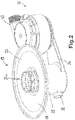
- the sump 19 is up to the out Fig. 2 easily recognizable large sump opening 20 or the like with an aforementioned flat sieve. covered.
- the sump 19 merges downward into a cylinder section 22 which has a central axis 30 shown in dash-dotted lines.
- the cylinder section 22 has a bottom 23 at the bottom.
- a grid insert 25, advantageously made of plastic, is placed on it or is located thereon.
- the grid insert 25 has an upper part 26a, a middle part 26b and a lower part 26c. From the Fig. 3 it can be clearly seen that the upper part 26a projects beyond the plane of the sump opening 20 and thus also a sieve or the like arranged here. pierces upwards. In the interior of the upper part 26a there is then no sieve or the like.
- the openings in the upper part 26a are the largest or larger than those in the central part 26b, which is designed to be slightly tapered downwards. This is in turn followed by the lower part 26c at the bottom with even smaller vertical grid openings.
- Coarser parts such as cherry stones can enter the central area through the large openings in the upper part 26a and are then held back by a coarse-part trap 28, which is formed at the bottom in the grille insert 25 mainly by the lower part 26c, from the rest of the sump. They can be flushed out to the left in a known manner to a sump drain outlet 32 and then drained off from the dishwasher 11 to a drain outlet 35.
- the sump discharge outlet 32 can accordingly Fig. 1 be arranged somewhat lower than the bottom 23 of the cylinder section 22 or the sump 19. Alternatively, according to the Figs. 2 to 4 also be arranged a little higher.
- a sump water outlet 34 extends horizontally to the right of the sump 19.
- the sump water outlet 32 leads to an impeller pump 36. This can pump or convey water, specifically through the water return 38 as a water line back to the rinsing arm 16 as circulation.
- the impeller pump 36 has, as its lowest part, a pump inlet 41 which extends from above into the sump water outlet 34 or the channel formed by it.
- the water return 38 is connected to a pump outlet 43, which according to FIGS Figs. 2 to 4 Is formed like a pipe socket. He stands according to the Fig. 3 and 4th at a right angle to a central axis 55 of the pump or a drive motor 54 for it.
- the impeller pump 36 has a pump chamber 45, which is provided in the lower region as a lower pump chamber 45a that is flat but wide. Seen upward in the axial direction, the pump chamber 45 extends into a narrow area as a circular pump chamber 45b.
- the pump outlet 43 leads away from here to the outside.
- An impeller 52 is arranged in the lower pump chamber 45a. It sits relatively close behind the pump inlet 41. Furthermore, a guide device 50 is provided in the transition between the two pump chambers 45a and 45b, which serves primarily to carry the water set in rotation by the impeller 52, which, so to speak, circulates in the pump chamber 45a to provide a movement component in the axial direction or to direct it in the axial direction. Thus, the water screws itself with a few revolutions, for example two to five revolutions, up to the pump outlet 43.
- the drive motor 54 of the impeller pump 36 has a central axis 55, shown in dash-dotted lines, which defines the aforementioned axial direction. It runs exactly vertically here.
- the drive motor 54 has a rotating stator 56 and a rotor 57 located therein with an axis 58 on which the impeller 52 is fastened.
- the impeller pump 36 has a heating system for pumped water on a jacket wall 47, which forms a large part of the outer wall of the pump chamber 45b and the complete border of the pump chamber 45a.
- At least one heating element 48 is provided on the outside of the jacket wall 47, which advantageously consists of metal. This is particularly advantageously a thick-film heating element with a plurality of tracks in order to essentially heat a large part of the surface of the jacket wall 47. So the water can be heated when pumping or pumping.
- FIG EP 2150165 B1 see FIG EP 2150165 B1 .
- the low overall height of the arrangement shown results primarily from the fact that the impeller pump 36 is no longer arranged below the sump 19, as is known from the prior art mentioned at the beginning. Rather, the arrangement provided next to it saves a considerable amount of overall height. Furthermore, the impeller pump 36 itself is designed to be as compact as possible when viewed in the axial direction, so that it has the lowest possible overall height when viewed in the axial direction, but in the exemplary embodiment provided here also enables the pumped water to be heated by means of the heating element 48.
- the pump chamber 45a and above all 45b must have a special shape, so that it is ensured that the pumped water remains in the pump chamber for a little longer. It can thus be heated up better, which explains the relatively large expansion of the pump chamber 45a and, above all, 45b in the axial direction. Because the drive motor 54 has, so to speak, been drawn inward into the interior of the pump chamber or is arranged there, the overall height of the arrangement is relatively low. In this way it can also be achieved that the pump outlet 43 is well above the impeller 52, forms the uppermost area of the pump chamber 45b and at least its uppermost area extends at least as high as the drive motor 54 or even a little higher. Thus, for example, the water return 38 can also be made somewhat shorter and, above all, can also easily lead away from the impeller pump 36.
- the impeller 52 is higher than the sump water outlet 34, in particular that which is also higher than the lowermost part of the sump drain outlet 32.
- the grid insert 25 is obviously advantageously designed as a plastic in order to be able to achieve the shape shown.
- the tapered recess 18 can either be strongly tapered, as this is the case Fig. 1 suggests, or only slightly tapers, like this the Fig. 3 and 4th demonstrate.
- the main issue here is that water can converge and drain over a large area in the lower area of the treatment room 14 or on its floor 17 and, in particular, after it has been cleaned and at least freed from coarse particles, it is returned to the treatment room by the impeller pump 36 14 can be pumped. In doing so, due to the passage through the heating element 48 in the pump chamber 45a and 45b, it can be heated by a few ° C. in each case, so that it can overall reach a desired temperature.
- the cylinder section 22 together with the sump drain outlet 32 is also advantageously manufactured as a one-piece part made of plastic.
- the sump water outlet 34 can also be integrally formed here; alternatively, it can be manufactured separately, which considerably simplifies manufacture. It can then be firmly and permanently connected to the cylinder section 22, for example glued or welded by means of plastic welding known per se.
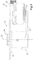
- FIG. 5 is a modification of the arrangement Fig. 3 shown with an additional additional outlet 144 from the impeller pump 136 or from its lower pump chamber, the impeller pump 136 otherwise being designed as in FIG Fig. 3 .
- the additional outlet 144 goes from below to a lower point or the lower pump chamber, which is not shown here but as in the sectional drawing of FIG Fig. 4 is trained. It is advantageously the lowest possible point of the lower pump chamber apart from the pump inlet 141.
- An outlet flap 146 shown in dashed lines, is provided here, as is shown in FIG DE 102017221732.4 is known to the same applicant with the filing date of December 17, 2017, to which reference is hereby explicitly made, and as explained above.
- the outlet flap 146 is in plan view of the Fig. 5 arranged in front of the impeller, the direction of rotation in Fig. 4 right out of the drawing plane and left into the drawing plane. With the resulting direction of circulation of the pumped water towards the pump outlet 143, the water flow presses the outlet flap 146 downwards or closes it and thus also the access to the additional outlet 144, so no water escapes.
- the outlet flap 146 is designed or spring-loaded in such a way that it is actually open by itself, as shown here by dashed lines. Residual water can thus even flow out of the pump chamber automatically into the additional outlet 144.
- the impeller pump 136 reverses its direction of rotation, the water in the pump chamber circulates in the opposite direction and is, so to speak, conveyed directly to the outlet flap 146 out of the pump chamber. It then exits to the additional outlet 144, advantageously to a drain outlet from the entire device. In this way, not only can the pump or its pump chamber itself be completely emptied, the sump can also be specifically pumped out.
Abstract
Eine Spülmaschine (11) weist eine verschließbare Behandlungskammer (14) für zu behandelndes Geschirr, mindestens einen Wassereinlass (38) in die Behandlungskammer (14), einen Sumpf (19) unten in der Behandlungskammer (14) und einen Sumpf-Wasserauslass (34) aus dem Sumpf (19) auf, der in seitlicher Richtung horizontal von dem Sumpf (19) wegführt. Eine Impellerpumpe (36) ist vorgesehen mit einem Pumpeneinlass (41), einem oberen Pumpenauslass (43), einer Pumpenkammer (45), einem in der Pumpenkammer (45) angeordneten Impeller (52) und einem Pumpenmotor (54) für den Impeller (52), wobei der Pumpeneinlass (41) mit dem Sumpf-Wasserauslass (34) verbunden ist. Die Pumpenkammer (45) läuft ringartig um und umgibt dabei den Pumpenmotor (54) in axialer Richtung gesehen zumindest teilweise. Der obere Pumpenauslass (43) ist höher angeordnet als der Impeller (52).A dishwasher (11) has a lockable treatment chamber (14) for dishes to be treated, at least one water inlet (38) into the treatment chamber (14), a sump (19) at the bottom of the treatment chamber (14) and a sump water outlet (34) from the sump (19), which leads away horizontally in the lateral direction from the sump (19). An impeller pump (36) is provided with a pump inlet (41), an upper pump outlet (43), a pump chamber (45), an impeller (52) arranged in the pump chamber (45) and a pump motor (54) for the impeller (52) ), the pump inlet (41) being connected to the sump water outlet (34). The pump chamber (45) runs around like a ring and surrounds the pump motor (54) at least partially as seen in the axial direction. The upper pump outlet (43) is arranged higher than the impeller (52).
Description
Die Erfindung betrifft ein wasserführendes Haushaltsgerät mit einem Wasserbehandlungsraum und mit einer Wasserführung vom bzw. zum Wasserbehandlungsraum, insbesondere auch davon weg. Ein solches Haushaltsgerät ist besonders vorteilhaft eine Spülmaschine oder eine Waschmaschine.The invention relates to a water-carrying household appliance with a water treatment room and with a water flow from or to the water treatment room, in particular also away from it. Such a household appliance is particularly advantageously a dishwasher or a washing machine.
Aus der
Aus der
Der Erfindung liegt die Aufgabe zugrunde, ein eingangs genanntes wasserführendes Haushaltsgerät zu schaffen, mit dem Probleme des Standes der Technik gelöst werden können und es insbesondere möglich ist, vorteilhaft Wasser im Haushaltsgerät pumpen zu können und dabei möglichst wenig Bauraum zu benötigen.The invention is based on the object of creating a water-carrying household appliance mentioned at the beginning with which problems of the prior art can be solved and in particular it is possible to advantageously be able to pump water in the household appliance while requiring as little space as possible.
Gelöst wird diese Aufgabe durch ein wasserführendes Haushaltsgerät mit den Merkmalen des Anspruchs 1. Vorteilhafte sowie bevorzugte Ausgestaltungen der Erfindung sind Gegenstand der weiteren Ansprüche und werden im Folgenden näher erläutert. Der Wortlaut der Ansprüche wird durch ausdrückliche Bezugnahme zum Inhalt der Beschreibung gemacht.This object is achieved by a water-conducting household appliance with the features of
Das wasserführende Haushaltsgerät weist neben dem Wasserbehandlungsraum und der Wasserführung zu diesem hin bzw. von diesem weg eben eine Behandlungskammer auf, die verschließbar ist und in der Gegenstände behandelt werden können. Im Falle einer Spülmaschine ist dies eine übliche im Wesentlichen kastenförmige Behandlungskammer, die von vorne mit einer Tür verschlossen werden kann. Darin können Geschirr und Besteck gereinigt werden. Im Falle einer Waschmaschine ist in der Behandlungskammer üblicherweise eine drehbare Trommel angeordnet, die von vorne oder alternativ von oben zugänglich ist und von einem Trommelmotor gedreht werden kann.The water-bearing household appliance has, in addition to the water treatment room and the water conduit towards and away from it, a treatment chamber which can be closed and in which objects can be treated. In the case of a dishwasher, this is a conventional, essentially box-shaped treatment chamber which can be closed from the front with a door. Crockery and cutlery can be cleaned in it. In the case of a washing machine, a rotatable drum is usually arranged in the treatment chamber, which is accessible from the front or alternatively from above and can be rotated by a drum motor.
Ein Wassereinlass ist in die Behandlungskammer vorgesehen, der vorteilhaft auf übliche Art und Weise ausgebildet sein kann. Unten in der Behandlungskammer ist ein Sumpf vorgesehen, der ebenfalls vorteilhaft auf übliche Art und Weise ausgebildet sein kann. Aus dem Sumpf führt ein Sumpf-Wasserauslass in seitlicher Richtung von diesem weg. Dabei kann er einen Winkel zur Horizontalen aufweisen, der zwischen 0° und maximal ± 25° liegt. Dies bedeutet, dass der Sumpf-Wasserauslass zwar in etwa horizontal seitlich wegführen kann, aber auch etwas nach oben bzw. vor allem nach unten geneigt sein kann. Es ist noch eine Impellerpumpe vorgesehen, die einen Pumpeneinlass, einen Pumpenauslass, eine Pumpenkammer dazwischen sowie einen darin angeordneten Impeller aufweist. Zum Antrieb des Impellers ist ein Pumpenmotor vorgesehen. Der Pumpeneinlass in die Pumpe bzw. in die Pumpenkammer ist dabei mit dem Sumpf-Wasserauslass verbunden. Vorteilhaft kann vorgesehen sein, dass ein Pumpenkammerdeckel direkt mit dem Sumpf-Wasserauslass verbunden ist, alternativ ein kurzer Rohrstutzen am Pumpenkammerdeckel damit verbunden ist. So kann in vertikaler Richtung gesehen die Pumpenkammer möglichst nahe am Sumpf-Wasserauslass sein bzw. möglichst nicht sehr hoch darüber angeordnet sein. Dadurch ist eine Reduktion der Bauhöhe möglich, was für solche Haushaltsgeräte besonders wichtig ist. Dann kann nämlich die Behandlungskammer möglicherweise größer ausgebildet sein.A water inlet is provided in the treatment chamber, which can advantageously be designed in the usual way. A sump is provided at the bottom of the treatment chamber, which can likewise advantageously be designed in the usual way. A sump water outlet leads away from the sump in a lateral direction. It can have an angle to the horizontal that is between 0 ° and a maximum of ± 25 °. This means that the sump water outlet can lead away to the side approximately horizontally, but can also be inclined slightly upwards or, above all, downwards. An impeller pump is also provided, which has a pump inlet, a pump outlet, a pump chamber in between and an impeller arranged therein. A pump motor is provided to drive the impeller. The pump inlet into the pump or into the pump chamber is connected to the sump water outlet. It can advantageously be provided that a pump chamber cover is connected directly to the sump water outlet, alternatively a short pipe socket on the pump chamber cover is connected to it. Thus, viewed in the vertical direction, the pump chamber can be as close as possible to the sump water outlet or, if possible, not very high above it. This makes it possible to reduce the overall height, which is particularly important for such household appliances. The treatment chamber can then possibly be made larger.
Erfindungsgemäß läuft die Pumpenkammer ringartig um bzw. ist zumindest teilweise ringartig ausgebildet, insbesondere schließt sie an einen Bereich um den Impeller herum an, vorteilhaft als eine Ringkammer. Es ist vorgesehen, dass die Pumpenkammer mindestens teilweise um den Pumpenmotor umläuft und/oder dass der Pumpenmotor in axialer Richtung gesehen zumindest teilweise von der Pumpenkammer umgeben ist. Des Weiteren ist der Pumpenauslass aus der Pumpe höher angeordnet als der Impeller, vorteilhaft liegt er in axialer Richtung gesehen im obersten Bereich der Pumpenkammer.According to the invention, the pump chamber runs around like a ring or is at least partially ring-like, in particular it adjoins an area around the impeller, advantageously as an annular chamber. It is provided that the pump chamber at least partially revolves around the pump motor and / or that the pump motor, viewed in the axial direction, is at least partially surrounded by the pump chamber. Furthermore, the pump outlet from the pump is arranged higher than the impeller; viewed in the axial direction, it is advantageously in the uppermost region of the pump chamber.
Somit ermöglicht es die Erfindung, den Pumpenmotor sozusagen in die Pumpenkammer hineinzuziehen bzw. die Pumpenkammer um den Pumpenmotor herumzuführen, wodurch die Pumpenkammer mit der ringartig um den Pumpenmotor umlaufenden Ausgestaltung zwar eine gewisse axiale Höhe aufweisen kann, dies aber die Bauhöhe nicht unbedingt vergrößert, da hier ja ohnehin der Pumpenmotor vorhanden ist und die beiden ineinander integriert sein können.The invention thus makes it possible to pull the pump motor into the pump chamber, so to speak, or to guide the pump chamber around the pump motor, whereby the pump chamber With the design that encircles the pump motor in a ring-like manner, it can have a certain axial height, but this does not necessarily increase the overall height, since the pump motor is present here anyway and the two can be integrated into one another.
In vorteilhafter Ausgestaltung der Erfindung ist der Sumpf-Wasserauslass unten am Sumpf vorgesehen, insbesondere ist er am untersten Bereich des Sumpfes vorgesehen. So kann vorgesehen sein, dass mittels der Impellerpumpe möglichst viel bzw. sämtliches Wasser aus dem Sumpf abgepumpt und somit entfernt werden kann. Dies ist aus hygienischen Gründen von Vorteil.In an advantageous embodiment of the invention, the sump water outlet is provided at the bottom of the sump, in particular it is provided at the lowest area of the sump. It can thus be provided that as much or all of the water as possible can be pumped out of the sump and thus removed by means of the impeller pump. This is an advantage for reasons of hygiene.
In weiterer vorteilhafter Ausgestaltung der Erfindung kann ein unterster Punkt des Pumpenauslasses in axialer Richtung der Pumpe gesehen auf Höhe des Antriebsmotors oder sogar höher als der Antriebsmotor liegen. Dies ermöglicht eben eine in axialer Richtung relativ langgestreckte Pumpenkammer, die aber die Bauhöhe nur unwesentlich erhöht oder gar nicht erhöht. Dies ist insbesondere dann von Vorteil, wenn, wie nachfolgend noch erläutert wird, in der Pumpenkammer oder an der Pumpenkammer eine Beheizung vorgesehen ist.In a further advantageous embodiment of the invention, a lowermost point of the pump outlet, viewed in the axial direction of the pump, can be at the level of the drive motor or even higher than the drive motor. This enables a pump chamber which is relatively elongated in the axial direction, but which increases the overall height only insignificantly or not at all. This is particularly advantageous when, as will be explained below, heating is provided in the pump chamber or on the pump chamber.
In bevorzugter Ausgestaltung der Erfindung ist der Sumpf zumindest in einem oberen Bereich trichterförmig ausgebildet, insbesondere dort, wo er sozusagen in die Behandlungskammer übergeht bzw. an diese anschließt. Bevorzugt ist er flach trichterförmig. Nach unten kann er verjüngt ausgebildet sein. Vorzugsweise kann er in einem unteren Bereich auch zylinderförmig bzw. rundzylindrisch ausgebildet sein, insbesondere im Wesentlichen vertikal verlaufend. Der Sumpf kann als Baueinheit aus mehreren Bauteilen ausgebildet sein, die miteinander verbunden sind. Eine solche Verbindung kann dauerhaft und unlösbar sein, insbesondere geklebt oder geschweißt sein. Alternativ können Teile zusammengesteckt oder verrastet sein. Der Sumpf kann im oberen Bereich, insbesondere im Wesentlichen an einer Oberkante, von einem Sieb oder einem ähnlichen flächigen Gebilde mit kleinen Öffnungen verschlossen sein, das vorzugsweise zur Mitte hin abgesenkt bzw. vertieft ist. In der Mitte kann eine Öffnung nach unten vorgesehen sein, die größere Gegenstände wie beispielsweise Kirschkerne in einer Geschirrspülmaschine hindurchlassen kann. So können sie gesammelt werden bzw. aus dem Wasser zum Umwälzen entfernt werden.In a preferred embodiment of the invention, the sump is funnel-shaped at least in an upper area, in particular where it, so to speak, merges into the treatment chamber or adjoins it. It is preferably flat, funnel-shaped. It can be tapered towards the bottom. It can preferably also be cylindrical or round cylindrical in a lower region, in particular running essentially vertically. The sump can be designed as a structural unit made up of several components that are connected to one another. Such a connection can be permanent and permanent, especially glued or welded. Alternatively, parts can be plugged together or locked. The sump can be closed in the upper area, in particular essentially at an upper edge, by a sieve or a similar flat structure with small openings, which is preferably lowered or deepened towards the center. A downward opening can be provided in the middle, which larger objects such as cherry stones can pass through in a dishwasher. So they can be collected or removed from the water for circulation.
Der Sumpf-Wasserauslass kann vorteilhaft in horizontaler Richtung zur Seite von dem Sumpf abgehen und zu der Impellerpumpe bzw. zu deren Pumpeneinlass führen. Der Sumpf-Wasserauslass kann dabei über diese Strecke hinweg als eine Art Kanal ausgebildet sein. Ein Boden des Sumpf-Wasserauslasses kann gleichzeitig einen wesentlichen Teil des Bodens des Sumpfes nach unten zu bilden oder in der gleichen Ebene mit diesem liegen.The sump water outlet can advantageously extend in the horizontal direction to the side of the sump and lead to the impeller pump or to its pump inlet. The sump water outlet can be designed as a type of channel over this route. A bottom of the sump water outlet can at the same time form a substantial part of the bottom of the sump or lie in the same plane with it.
In axialer Richtung gesehen kann der Impeller vorteilhaft auf Höhe des Sumpfes angeordnet sein. Somit liegt er also höher als der Sumpf-Wasserauslass. Auch der Pumpenmotor liegt vorteilhaft in axialer Richtung gesehen auf Höhe des Sumpfes, in der Praxis einige Zentimeter oberhalb des Impellers. Besonders vorteilhaft kann auch der Pumpenauslass in axialer Richtung gesehen auf Höhe des Sumpfes angeordnet sein, zumindest unterhalb eines vorgenannten Siebs oder Gebildes als oberer Abschluss des Sumpfes hin zur Behandlungskammer. Somit kann die gesamte Impellerpumpe eine Höhe in axialer Richtung aufweisen, die in etwa der Höhe des Sumpfes als vorgenannte Baueinheit entspricht oder diese nicht überragt. Durch diese Bauweise kann erkennbar die gesamte vertikale Höhe minimiert werden.Viewed in the axial direction, the impeller can advantageously be arranged at the level of the sump. It is therefore higher than the sump water outlet. The pump motor is also advantageously at the level of the sump when viewed in the axial direction, in practice a few centimeters above the impeller. Particularly advantageously, the pump outlet can also be arranged at the level of the sump, seen in the axial direction, at least below an aforementioned sieve or structure as the upper closure of the sump towards the treatment chamber. The entire impeller pump can thus have a height in the axial direction which corresponds approximately to the height of the sump as the aforementioned structural unit or does not protrude beyond it. With this design, the entire vertical height can be visibly minimized.
In Ausgestaltung der Erfindung kann der Pumpenauslass in einer Richtung im Wesentlichen rechtwinklig zur Drehachse des Impellers verlaufen, also zur Seite hin abgehen. Diese Verlaufsrichtung ist insbesondere dort gegeben, wo der Pumpenauslass aus einer Verlängerung einer Mantelform der Pumpenkammer heraustritt. In diesem Bereich sollte also seine Verlaufsrichtung im Wesentlichen rechtwinklig zur Drehachse des Impellers sein. Er kann vorteilhaft tangential von der Pumpenkammer abgehen. Danach kann er unter Umständen auch abgebogen sein oder schräg nach oben bzw. nach unten geführt sein. Da vom Impeller in Rotation versetztes Wasser mehrere Male in der Pumpenkammer umlaufen kann, schraubt es sich sozusagen vom Impeller nach oben bis hin zu dem Pumpenauslass.In an embodiment of the invention, the pump outlet can run in a direction essentially at right angles to the axis of rotation of the impeller, that is, it can branch off to the side. This direction of progress is given in particular where the pump outlet emerges from an extension of a shell shape of the pump chamber. In this area, its direction should be essentially perpendicular to the axis of rotation of the impeller. It can advantageously extend tangentially from the pump chamber. After that, under certain circumstances it can also be bent or inclined upwards or downwards. Since water set in rotation by the impeller can circulate several times in the pump chamber, it so to speak scrolls upwards from the impeller to the pump outlet.
In bevorzugter Ausgestaltung der Erfindung ist der vorgenannte Pumpenauslass als oberster Bereich bzw. als oberstes Teil der Pumpenkammer ausgebildet. Vorteilhaft kann der Pumpenauslass auch den obersten Bereich der gesamten Impellerpumpe bilden bzw. der Rest der Impellerpumpe liegt darunter. Auch dies hilft, die axiale Bauhöhe gering zu halten.In a preferred embodiment of the invention, the aforementioned pump outlet is designed as the uppermost area or as the uppermost part of the pump chamber. The pump outlet can advantageously also form the uppermost area of the entire impeller pump or the rest of the impeller pump lies below it. This also helps to keep the axial overall height low.
Bevorzugt ist in oder an der Pumpenkammer mindestens ein Heizelement vorgesehen. Besonders bevorzugt kann ein solches Heizelement an einer Außenseite der Pumpenkammer vorgesehen sein. Es kann in axialer Richtung gesehen auf Höhe des Impellers angeordnet sein, so dass von dem Impeller gefördertes Wasser möglichst direkt an die Wandung der Pumpenkammer kommt, wo es dann von dem mindestens einen Heizelement beheizt werden kann. In weiterer Ausgestaltung der Erfindung kann das Heizelement den Impeller in axialer Richtung gesehen nach oben überragen. Somit kann das vom Impeller geförderte Wasser möglichst gut beheizt werden, insbesondere wenn es in der Pumpenkammer anschließend umläuft hin zum Pumpenauslass.At least one heating element is preferably provided in or on the pump chamber. Such a heating element can particularly preferably be provided on an outside of the pump chamber. It can be arranged at the level of the impeller, seen in the axial direction, so that water conveyed by the impeller comes as directly as possible to the wall of the pump chamber, where it can then be heated by the at least one heating element. In a further embodiment of the invention, the heating element can protrude upward beyond the impeller as seen in the axial direction. The water conveyed by the impeller can thus be heated as well as possible, in particular if it then circulates in the pump chamber towards the pump outlet.
In vorteilhafter Ausgestaltung der Erfindung kann der Pumpenmotor als Nassläufer ausgebildet sein. Er kann vom Wasser aus der Pumpenkammer umspült sein. Die entstehende Abwärme des Pumpenmotors kann ins Wasser abgeleitet werden, was somit zu einem besseren und effizienteren Gesamtsystem führen kann bzw. was zu einer besseren Effizienz der Wärmeeinleitung ins Wasser führen kann.In an advantageous embodiment of the invention, the pump motor can be designed as a wet rotor. It can be washed around by the water from the pump chamber. The resulting waste heat of the pump motor can be diverted into the water, which can thus lead to a better and more efficient overall system or which can lead to better efficiency in the introduction of heat into the water.
Bevorzugt ist eine Drehachse des Impellers vertikal ausgerichtet, so dass die vorgenannte axiale Richtung des Pumpenmotors die Vertikale ist. Dadurch kann, insbesondere wenn auch der Sumpf samt unterem rundzylindrischem Bereich vertikal ausgerichtet ist, eine maximal kompakte Bauform erreicht werden.An axis of rotation of the impeller is preferably oriented vertically, so that the aforementioned axial direction of the pump motor is the vertical. As a result, a maximally compact design can be achieved, especially if the sump together with the lower round cylindrical area is aligned vertically.
In weiterer Ausgestaltung der Erfindung kann vorgesehen sein, dass vom Sumpf ein weiterer Sumpf-Ablaufauslass abgeht. Dieser kann besonders vorteilhaft von der tiefsten Stelle des Sumpfes aus abgehen. Der Sumpf-Ablaufauslass kann zu einem Ablaufauslass aus dem ganzen Haushaltsgerät führen, entweder direkt oder über eine Abfluss-Pumpe zum Herauspumpen des Wassers aus dem Haushaltsgerät zu dem vorgenannten Abfluss-Auslass heraus. An einem solchen Sumpf-Ablaufauslass können gröbere bzw. größere Teile aus dem Wasser der Behandlungskammer, beispielsweise mit einer Größe ab 5 mm wie Kirschkerne in einer Spülmaschine, die von einer sogenannten Grobteil-Falle unten im Sumpf zurückgehalten worden sind, und aus dem Haushaltsgerät herausgespült werden. So müssen sie nicht von einer Bedienperson von Hand entfernt werden. Des Weiteren kann durch die vorgenannte Grobteil-Falle, möglicherweise auch durch weitere Siebe oder Filtereinrichtungen im Sumpf oder dahinter, verhindert werden, dass diese Teile in die Impellerpumpe gelangen. Sie könnten deren Funktion beeinträchtigen, sie insbesondere beschädigen oder sogar zerstören. Ein solcher Sumpf-Ablaufauslass kann sich direkt an eine Grobteil-Falle anschließen. Insbesondere kann der Sumpf-Ablaufauslass leicht abschüssig sein bzw. von der Grobteil-Falle aus nach unten verlaufen, damit Grobteile leicht ausgespült werden können und auf keinen Fall zurück in den Sumpf oder den Behandlungsraum gelangen können.In a further embodiment of the invention, it can be provided that a further sump drain outlet extends from the sump. This can come off particularly advantageously from the deepest point of the sump. The sump drain outlet can lead to a drain outlet from the entire household appliance, either directly or via a drain pump for pumping the water out of the household appliance to the aforementioned drain outlet. At such a sump drain outlet, coarser or larger parts of the water in the treatment chamber, for example with a size of 5 mm or more such as cherry stones in a dishwasher, which have been held back by a so-called coarse-part trap at the bottom of the sump, and flushed out of the household appliance will. They do not have to be removed by hand by an operator. Furthermore, the above-mentioned coarse-part trap, possibly also by further sieves or filter devices in the sump or behind it, can prevent these parts from getting into the impeller pump. They could impair their function, in particular damage or even destroy them. Such a sump drainage outlet can connect directly to a coarse-part trap. In particular, the sump drain outlet can be slightly sloping or run downwards from the coarse-part trap so that coarse parts can be easily rinsed out and in no case can they get back into the sump or the treatment room.
In vorteilhafter Ausgestaltung der Erfindung ist der untere Teil des Sumpfes von einem einzigen Sumpf-Bauteil gebildet, welches einstückig ausgebildet ist. Dies betrifft insbesondere eine rohrartige Ausgestaltung des Sumpfes unterhalb der Trichterform oder der erweiterten Form, wobei der Sumpf-Wasserauslass einstückig von dem Bauteil abgeht und zu der Impellerpumpe führt. Hier kann der Sumpf-Abflussauslass auch an dem Bauteil vorgesehen sein, insbesondere als ein vom Sumpf abgehender Rohrstutzen. Er kann eben auch einstückig mit dem Sumpf-Bauteil ausgebildet sein. Durch die einstückige Ausgestaltung entsteht zwar ein höherer Fertigungsaufwand. Gleichzeitig kann aber die Gefahr von Undichtigkeiten bzw. auch ein Aufwand für eine Abdichtung reduziert werden, was als sehr vorteilhaft angesehen wird.In an advantageous embodiment of the invention, the lower part of the sump is formed by a single sump component which is formed in one piece. This relates in particular to a tubular design of the sump below the funnel shape or the expanded shape, the sump water outlet extending in one piece from the component and leading to the impeller pump. Here, the sump drain outlet can also be provided on the component, in particular as a pipe socket extending from the sump. It can also be designed in one piece with the sump component. The one-piece design results in a higher manufacturing cost. At the same time, however, the risk of leaks or the expense for a seal can be reduced, which is considered to be very advantageous.
Die Pumpenkammer kann vorteilhaft mit ringförmigem Querschnitt um den Pumpenmotor umlaufend ausgebildet sein, insbesondere mit kreisringförmigem Querschnitt, und dies zumindest teilweise in axialer Richtung gesehen über dessen Höhe. Ein Teil der Außenwandung der Pumpenkammer kann von einem vorgenannten Heizelement beheizt sein bzw. das Heizelement auf der Außenseite aufweisen. So können mindestens 50 % der Pumpenkammer beheizt sein, insbesondere 60 % bis 80 %.The pump chamber can advantageously be designed with an annular cross-section around the pump motor, in particular with an annular cross-section, and this at least partially over its height as seen in the axial direction. Part of the outer wall of the pump chamber can be heated by an aforementioned heating element or have the heating element on the outside. At least 50% of the pump chamber can be heated, in particular 60% to 80%.
Der Pumpenauslass kann vorteilhaft den höchsten Bereich der Impellerpumpe bilden, wenn man sie als Baueinheit betrachtet. Er kann in einen Rohrstutzen übergehen, der zwischen 2 cm und 5 cm lang ist, und von der Verlängerung der Mantelform von der Außenseite der Pumpenkammer abstehen. An den Rohrstutzen können eine Wasserleitung oder ein Schlauch angeschlossen werden.The pump outlet can advantageously form the highest area of the impeller pump when viewed as a structural unit. It can merge into a pipe socket that is between 2 cm and 5 cm long and protrudes from the extension of the jacket shape from the outside of the pump chamber. A water pipe or a hose can be connected to the pipe socket.
In weiterer Ausgestaltung der Erfindung ist ein Zusatz-Auslass aus der Pumpenkammer vorgesehen samt einer Zusatz-Auslassklappe daran bzw. dafür. Die Zusatz-Auslassklappe weist eine Geschlossen-Stellung und mindestens eine Offen-Stellung auf. Zwischen diesen beiden Stellungen ist sie bewegbar, vorteilhaft drehbar ausgebildet, alternativ verbiegbar. Vorzugsweise ist sie dabei um eine Achse drehbar ausgebildet, ist also drehbar gelagert und nicht nur elastisch bewegbar und auslenkbar ausgebildet, beispielsweise durch Verbiegung oder Verwindung. In der Geschlossen-Stellung verschließt die Zusatz-Auslassklappe den Zusatz-Auslass, vorteilhaft weitgehend oder sogar vollständig. Dazu kann die Zusatz-Auslassklappe in etwa so groß sein wie der Zusatz-Auslass, vorteilhaft etwas größer sein. In jeder der Offen-Stellungen ist der Zusatz-Auslass zumindest teilweise offen bzw. die Zusatz-Auslassklappe gibt ihn zumindest teilweise frei oder öffnet ihn. Abhängig von der Offen-Stellung kann der Zusatz-Auslass also mehr oder weniger offen sein.In a further embodiment of the invention, an additional outlet from the pump chamber is provided, including an additional outlet flap thereon or for it. The additional outlet flap has a closed position and at least one open position. Between these two positions it is movable, advantageously designed to be rotatable, alternatively bendable. It is preferably designed to be rotatable about an axis, that is to say it is rotatably mounted and not only designed to be elastically movable and deflectable, for example by bending or twisting. In the closed position, the additional outlet flap closes the additional outlet, advantageously largely or even completely. For this purpose, the additional outlet flap can be approximately as large as the additional outlet, advantageously somewhat larger. In each of the open positions, the additional outlet is at least partially open or the additional outlet flap at least partially releases or opens it. Depending on the open position, the additional outlet can therefore be more or less open.
Zusätzlich ist ein Stellmittel vorgesehen, wodurch die Zusatz-Auslassklappe derart kraftbelastet ist, dass sie selbsttätig aus der Geschlossen-Stellung in eine der Offen-Stellungen bewegt wird, wenn kein Fluid bzw. Wasser vom Einlass zum Auslass gepumpt wird bzw. wenn die Zusatz-Auslassklappe frei ist von Fluidströmung in Drehrichtung des Impellers zum Pumpen des Fluids im normalen Betrieb. Das Stellmittel kann also die Zusatz-Auslassklappe zumindest in die erste Offen-Stellung bzw. in die am wenigsten geöffnete Offen-Stellung bringen. Unter Umständen kann es also ausreichen, wenn die Stellmittel die Zusatz-Auslassklappe nur ein klein wenig öffnen. Damit kann erreicht werden, dass in der Geschlossen-Stellung kein Fluid während des Pumpens durch den Zusatz-Auslass entweicht bzw. aus der Pumpenkammer gefördert wird. Schließlich soll das Fluid ja normal vom Einlass zum Auslass gefördert werden. Die Fluidströmung kann hier sogar noch helfen, die Zusatz-Auslassklappe in der Geschlossen-Stellung zu halten, da sie diese beispielsweise niederdrückt. Wenn keine Fluidströmung vorliegt, soll sich die Zusatz-Auslassklappe selbsttätig zumindest teilweise öffnen. Dann kann durch Dreh-richtungsumkehr des Impellers, wie nachfolgend noch erläutert wird, in die zumindest teilweise geöffnete Zusatz-Auslassklappe gefördert werden bzw. an dieser vorbei in den nun zumindest teilweise offenen Zusatz-Auslass hinein und somit Fluid an einen anderen Abgang der Impellerpumpe, vorzugsweise zu einer Abflussleitung hin, gebracht werden.In addition, an adjusting means is provided, whereby the additional outlet flap is so force-loaded that it is automatically moved from the closed position into one of the open positions when no fluid or water is pumped from the inlet to the outlet or when the additional The outlet flap is free of fluid flow in the direction of rotation of the impeller for pumping the fluid during normal operation. The adjusting means can therefore bring the additional outlet flap at least into the first open position or into the least open open position. Under certain circumstances it can therefore be sufficient if the actuating means open the additional outlet flap only a little. It can thus be achieved that in the closed position no fluid escapes through the additional outlet or is conveyed out of the pump chamber during pumping. After all, the fluid should be conveyed normally from the inlet to the outlet. The fluid flow can even help to close the additional outlet flap in the closed position hold, as it depresses it, for example. If there is no fluid flow, the additional outlet flap should automatically open at least partially. Then, by reversing the direction of rotation of the impeller, as will be explained below, it is possible to convey into the at least partially open additional outlet flap or past it into the now at least partially open additional outlet and thus fluid to another outlet of the impeller pump, preferably to a drainage line.
Durch die spezielle Ausbildung der Zusatz-Auslassklappe samt Stellmittel, die vorteilhaft passive Stellmittel sind wie besonders vorteilhaft eine elastische Ausgestaltung oder eine separate Feder, mit der selbsttätigen Öffnung kann auf speziell anzusteuernde Aktoren wie Elektromagnete, Piezo-Antriebe oder Elektromotoren verzichtet werden. Dies vereinfacht die Konstruktion der Impellerpumpe sowie deren Betrieb erheblich. Des Weiteren kann auch Bauraum eingespart werden.Due to the special design of the additional outlet flap including actuating means, which are advantageously passive actuating means, particularly advantageously an elastic design or a separate spring, with the automatic opening, actuators such as electromagnets, piezo drives or electric motors that need to be controlled specifically can be dispensed with. This considerably simplifies the construction of the impeller pump and its operation. Furthermore, installation space can also be saved.
Diese und weitere Merkmale gehen außer aus den Ansprüchen auch aus der Beschreibung und den Zeichnungen hervor, wobei die einzelnen Merkmale jeweils für sich allein oder zu mehreren in Form von Unterkombinationen bei einer Ausführungsform der Erfindung und auf anderen Gebieten verwirklicht sein und vorteilhafte sowie für sich schutzfähige Ausführungen darstellen können, für die hier Schutz beansprucht wird. Die Unterteilung der Anmeldung in Zwischen-Überschriften und einzelne Abschnitte beschränkt die unter diesen gemachten Aussagen nicht in ihrer Allgemeingültigkeit.These and other features emerge from the claims and also from the description and the drawings, the individual features being implemented individually or in combination in the form of sub-combinations in one embodiment of the invention and in other areas and being advantageous and protectable per se Can represent designs for which protection is claimed here. The subdivision of the application into sub-headings and individual sections does not limit the general validity of the statements made under these.
Ausführungsbeispiele der Erfindung sind in den Zeichnungen schematisch dargestellt und werden im Folgenden näher erläutert. In den Zeichnungen zeigen:
- Fig. 1
- eine schematische Ansicht einer Spülmaschine als erfindungsgemäßes wasserführendes Haushaltsgerät,
- Fig. 2
- eine Schrägansicht von oben auf einen Sumpf der Spülmaschine samt Sumpf-Wasserauslass und daneben angeordneter Impellerpumpe,
- Fig. 3
- eine Seitenansicht der Anordnung aus
Fig. 2 , - Fig. 4
- einen Schnitt durch die Anordnung aus
Fig. 3 und - Fig. 5
- eine Abwandlung der Anordnung aus
Fig. 3 mit einem zusätzlichen Zusatz-Auslass aus der Pumpenkammer der Impellerpumpe.
- Fig. 1
- a schematic view of a dishwasher as a water-carrying household appliance according to the invention,
- Fig. 2
- an oblique view from above of a sump of the dishwasher including the sump water outlet and an impeller pump arranged next to it,
- Fig. 3
- a side view of the arrangement
Fig. 2 , - Fig. 4
- a section through the arrangement
Fig. 3 and - Fig. 5
- a modification of the arrangement
Fig. 3 with an additional additional outlet from the pump chamber of the impeller pump.
In der
Der Sumpf 19 ist nach oben zu an der aus
Ein Sumpf-Wasserauslass 34 geht horizontal nach rechts vom Sumpf 19 weg. Der Sumpf-Wasserauslass 32 führt zu einer Impellerpumpe 36. Diese kann Wasser pumpen bzw. fördern, und zwar durch die Wasserrückführung 38 als Wasserleitung zurück zum Spülarm 16 als Umwälzen.A
Die Impellerpumpe 36 weist als untersten Teil einen Pumpeneinlass 41 auf, der von oben in den Sumpf-Wasserauslass 34 bzw. den davon gebildeten Kanal hineinreicht. Die Wasserrückführung 38 ist an einen Pumpenauslass 43 angeschlossen, der gemäß den
Die Impellerpumpe 36 weist eine Pumpenkammer 45 auf, die im unteren Bereich als eine zwar flache, aber breite untere Pumpenkammer 45a vorgesehen ist. Nach oben zu in axialer Richtung gesehen geht die Pumpenkammer 45 in einen schmalen Bereich als kreisringförmige Pumpenkammer 45b. Von hieraus führt nach außen der Pumpenauslass 43 weg.The
In der unteren Pumpenkammer 45a ist ein Impeller 52 angeordnet. Er sitzt relativ knapp hinter dem Pumpeneinlass 41. Des Weiteren ist im Übergang zwischen den beiden Pumpenkammern 45a und 45b eine Leitvorrichtung 50 vorgesehen, die vor allem dazu dient, das vom Impeller 52 in Rotation versetzte Wasser, das in der Pumpenkammer 45a sozusagen umläuft, mit einer Bewegungskomponente in axialer Richtung zu versehen bzw. es auch in axialer Richtung zu leiten. So schraubt sich das Wasser mit einigen Umdrehungen, beispielsweise zwei bis fünf Umdrehungen, bis zum Pumpenauslass 43.An
Der Antriebsmotor 54 der Impellerpumpe 36 weist eine strichpunktiert dargestellte Mittelachse 55 auf, die die zuvor genannte axiale Richtung definiert. Sie verläuft hier genau vertikal. Der Antriebsmotor 54 weist einen umlaufenden Stator 56 und einen darin befindlichen Rotor 57 mit einer Achse 58 auf, auf der der Impeller 52 befestigt ist.The
Des Weiteren weist die Impellerpumpe 36 eine Beheizung von gefördertem Wasser an einer Mantelwand 47 auf, welche einen großen Teil der äußeren Wandung der Pumpenkammer 45b und die vollständige Umrandung der Pumpenkammer 45a bildet. Außen an der Mantelwand 47, die vorteilhaft aus Metall besteht, ist mindestens ein Heizelement 48 vorgesehen. Dieses ist besonders vorteilhaft ein Dickschichtheizelement mit mehreren Bahnen, um im Wesentlichen einen Großteil der Fläche der Mantelwand 47 zu beheizen. So kann das Wasser beim Fördern bzw. Pumpen beheizt werden. Dies ist aber grundsätzlich aus dem Stand der Technik bekannt, siehe die
Aus den Darstellungen, insbesondere den
Es ist aus der
Zum Sumpf 19 ist noch zu sagen, dass er aus Kunststoff hergestellt sein kann. Insbesondere ist der Gittereinsatz 25 offensichtlich vorteilhaft als Kunststoff ausgebildet um die dargestellte Form erreichen zu können. Die sich verjüngende Vertiefung 18 kann entweder stark verjüngt ausgebildet sein, wie dies die
Auch der Zylinderabschnitt 22 samt dem Sumpf-Ablaufauslass 32 ist vorteilhaft als einstückiges Teil aus Kunststoff gefertigt. Der Sumpf-Wasserauslass 34 kann hier ebenso angeformt sein, alternativ kann er separat hergestellt sein, was die Herstellbarkeit erheblich vereinfacht. Er kann dann fest und dauerhaft mit dem Zylinderabschnitt 22 verbunden werden, beispielsweise verklebt oder angeschweißt werden mittels an sich bekanntem Kunststoffschweißen.The
In der
Die Auslass-Klappe 146 ist in Draufsicht auf die
Claims (15)
Applications Claiming Priority (1)
| Application Number | Priority Date | Filing Date | Title |
|---|---|---|---|
| DE102019206203.2A DE102019206203A1 (en) | 2019-04-30 | 2019-04-30 | Water-bearing household appliance |
Publications (1)
| Publication Number | Publication Date |
|---|---|
| EP3733040A1 true EP3733040A1 (en) | 2020-11-04 |
Family
ID=70289321
Family Applications (1)
| Application Number | Title | Priority Date | Filing Date |
|---|---|---|---|
| EP20169290.2A Withdrawn EP3733040A1 (en) | 2019-04-30 | 2020-04-14 | Water-transporting household device |
Country Status (3)
| Country | Link |
|---|---|
| EP (1) | EP3733040A1 (en) |
| CN (1) | CN111839413A (en) |
| DE (1) | DE102019206203A1 (en) |
Families Citing this family (1)
| Publication number | Priority date | Publication date | Assignee | Title |
|---|---|---|---|---|
| DE102021205247A1 (en) * | 2021-05-21 | 2022-11-24 | E.G.O. Elektro-Gerätebau GmbH | Pump for a water-bearing household appliance and water-bearing household appliance with such a pump |
Citations (9)
| Publication number | Priority date | Publication date | Assignee | Title |
|---|---|---|---|---|
| US3918479A (en) * | 1971-11-03 | 1975-11-11 | Tappan Co | Heat system for dishwasher |
| JP2006220034A (en) * | 2005-02-09 | 2006-08-24 | Nidec Shibaura Corp | Pump and dish washer |
| WO2011091809A1 (en) * | 2010-01-26 | 2011-08-04 | Gardena Manufacturing Gmbh | Garden pump arrangement |
| US20110290284A1 (en) * | 2010-06-01 | 2011-12-01 | Moon Kee Chung | Dish washer |
| EP2150165B1 (en) | 2007-04-12 | 2012-10-10 | BSH Bosch und Siemens Hausgeräte GmbH | Pump having a heating device |
| EP2862494A1 (en) | 2013-10-14 | 2015-04-22 | E.G.O. Elektro-Gerätebau GmbH | Water-transporting household device |
| US20160097392A1 (en) * | 2014-10-07 | 2016-04-07 | General Electric Company | Pump assembly for appliance |
| US20170143180A1 (en) * | 2015-11-19 | 2017-05-25 | General Electric Company | Single Drive Axis Motor for a Dishwasher Spray System |
| WO2019025849A1 (en) | 2017-08-03 | 2019-02-07 | J.P. Industries S.P.A. | Priming or suction tank for washing machines |
Family Cites Families (4)
| Publication number | Priority date | Publication date | Assignee | Title |
|---|---|---|---|---|
| DE10133130A1 (en) * | 2001-07-07 | 2003-01-16 | Miele & Cie | Circulation pump with/without heating device, especially for supplying washing liquid to dishwasher spray arms, has water switch integrated into circulation pump |
| DE102013211180A1 (en) * | 2013-06-14 | 2014-12-18 | E.G.O. Elektro-Gerätebau GmbH | pump |
| EP2818090B1 (en) * | 2013-06-27 | 2016-08-17 | Samsung Electronics Co., Ltd | Dish washing machine and sump assembly thereof |
| DE102017221732A1 (en) * | 2017-12-01 | 2019-06-06 | E.G.O. Elektro-Gerätebau GmbH | impeller |
-
2019
- 2019-04-30 DE DE102019206203.2A patent/DE102019206203A1/en not_active Withdrawn
-
2020
- 2020-04-14 EP EP20169290.2A patent/EP3733040A1/en not_active Withdrawn
- 2020-04-29 CN CN202010356829.0A patent/CN111839413A/en active Pending
Patent Citations (9)
| Publication number | Priority date | Publication date | Assignee | Title |
|---|---|---|---|---|
| US3918479A (en) * | 1971-11-03 | 1975-11-11 | Tappan Co | Heat system for dishwasher |
| JP2006220034A (en) * | 2005-02-09 | 2006-08-24 | Nidec Shibaura Corp | Pump and dish washer |
| EP2150165B1 (en) | 2007-04-12 | 2012-10-10 | BSH Bosch und Siemens Hausgeräte GmbH | Pump having a heating device |
| WO2011091809A1 (en) * | 2010-01-26 | 2011-08-04 | Gardena Manufacturing Gmbh | Garden pump arrangement |
| US20110290284A1 (en) * | 2010-06-01 | 2011-12-01 | Moon Kee Chung | Dish washer |
| EP2862494A1 (en) | 2013-10-14 | 2015-04-22 | E.G.O. Elektro-Gerätebau GmbH | Water-transporting household device |
| US20160097392A1 (en) * | 2014-10-07 | 2016-04-07 | General Electric Company | Pump assembly for appliance |
| US20170143180A1 (en) * | 2015-11-19 | 2017-05-25 | General Electric Company | Single Drive Axis Motor for a Dishwasher Spray System |
| WO2019025849A1 (en) | 2017-08-03 | 2019-02-07 | J.P. Industries S.P.A. | Priming or suction tank for washing machines |
Also Published As
| Publication number | Publication date |
|---|---|
| DE102019206203A1 (en) | 2020-11-05 |
| CN111839413A (en) | 2020-10-30 |
Similar Documents
| Publication | Publication Date | Title |
|---|---|---|
| DE102012103419B4 (en) | Rotary filter for dishwashers | |
| DE112010001512T5 (en) | dishwasher | |
| DE102012102182A1 (en) | Dishwasher with filter arrangement | |
| EP2703093B1 (en) | Washing device for cleaning parts such as machine parts or the like | |
| DE1628625A1 (en) | Liquid distribution system for dishwashers | |
| EP1913262B1 (en) | Pump body, pump and a water supply household appliance | |
| DE1403118A1 (en) | Dish washing machine | |
| DE112005000850T5 (en) | Heater mounting construction for a dishwasher and heater | |
| EP3492752B1 (en) | Impeller pump | |
| EP2022882B1 (en) | Barrel for a washing machine and washing machine | |
| EP3733040A1 (en) | Water-transporting household device | |
| EP1763391B1 (en) | Device for holding and separating chippings and cooling liquid accumulating on machine tools | |
| EP3041983B1 (en) | Household appliance with conversion valve | |
| EP2862494B1 (en) | Water-transporting household device | |
| EP2699141B1 (en) | Dishwasher | |
| DE2022270A1 (en) | Washing machine, in particular a dishwasher | |
| DE1428475A1 (en) | Device for the water circulation in a dishwasher | |
| DE102015212653B4 (en) | HOUSEHOLD APPLIANCE | |
| EP0925817A1 (en) | Rinsable filter | |
| EP3569134B1 (en) | Cleaning and/or disinfection machine | |
| DE102014001435B4 (en) | washing machine | |
| DE2947941C2 (en) | Washing machine | |
| EP3545812B1 (en) | Dishwasher, in particular household dishwasher | |
| AT201271B (en) | dishwasher | |
| DE8317398U1 (en) | DISHWASHER |
Legal Events
| Date | Code | Title | Description |
|---|---|---|---|
| PUAI | Public reference made under article 153(3) epc to a published international application that has entered the european phase |
Free format text: ORIGINAL CODE: 0009012 |
|
| STAA | Information on the status of an ep patent application or granted ep patent |
Free format text: STATUS: THE APPLICATION HAS BEEN PUBLISHED |
|
| AK | Designated contracting states |
Kind code of ref document: A1 Designated state(s): AL AT BE BG CH CY CZ DE DK EE ES FI FR GB GR HR HU IE IS IT LI LT LU LV MC MK MT NL NO PL PT RO RS SE SI SK SM TR |
|
| AX | Request for extension of the european patent |
Extension state: BA ME |
|
| STAA | Information on the status of an ep patent application or granted ep patent |
Free format text: STATUS: THE APPLICATION IS DEEMED TO BE WITHDRAWN |
|
| 18D | Application deemed to be withdrawn |
Effective date: 20210505 |