EP3731385A1 - Agencement améliorée d'une unité de convertisseur et de moteur - Google Patents
Agencement améliorée d'une unité de convertisseur et de moteur Download PDFInfo
- Publication number
- EP3731385A1 EP3731385A1 EP19170867.6A EP19170867A EP3731385A1 EP 3731385 A1 EP3731385 A1 EP 3731385A1 EP 19170867 A EP19170867 A EP 19170867A EP 3731385 A1 EP3731385 A1 EP 3731385A1
- Authority
- EP
- European Patent Office
- Prior art keywords
- machine
- converter
- sensor
- machine arrangement
- arrangement according
- Prior art date
- Legal status (The legal status is an assumption and is not a legal conclusion. Google has not performed a legal analysis and makes no representation as to the accuracy of the status listed.)
- Withdrawn
Links
Images


Classifications
-
- H—ELECTRICITY
- H02—GENERATION; CONVERSION OR DISTRIBUTION OF ELECTRIC POWER
- H02K—DYNAMO-ELECTRIC MACHINES
- H02K11/00—Structural association of dynamo-electric machines with electric components or with devices for shielding, monitoring or protection
- H02K11/30—Structural association with control circuits or drive circuits
- H02K11/33—Drive circuits, e.g. power electronics
-
- H—ELECTRICITY
- H02—GENERATION; CONVERSION OR DISTRIBUTION OF ELECTRIC POWER
- H02K—DYNAMO-ELECTRIC MACHINES
- H02K11/00—Structural association of dynamo-electric machines with electric components or with devices for shielding, monitoring or protection
- H02K11/20—Structural association of dynamo-electric machines with electric components or with devices for shielding, monitoring or protection for measuring, monitoring, testing, protecting or switching
- H02K11/21—Devices for sensing speed or position, or actuated thereby
-
- H—ELECTRICITY
- H02—GENERATION; CONVERSION OR DISTRIBUTION OF ELECTRIC POWER
- H02K—DYNAMO-ELECTRIC MACHINES
- H02K9/00—Arrangements for cooling or ventilating
- H02K9/02—Arrangements for cooling or ventilating by ambient air flowing through the machine
- H02K9/04—Arrangements for cooling or ventilating by ambient air flowing through the machine having means for generating a flow of cooling medium
- H02K9/06—Arrangements for cooling or ventilating by ambient air flowing through the machine having means for generating a flow of cooling medium with fans or impellers driven by the machine shaft
-
- H—ELECTRICITY
- H02—GENERATION; CONVERSION OR DISTRIBUTION OF ELECTRIC POWER
- H02K—DYNAMO-ELECTRIC MACHINES
- H02K3/00—Details of windings
- H02K3/46—Fastening of windings on the stator or rotor structure
- H02K3/50—Fastening of winding heads, equalising connectors, or connections thereto
Definitions
- axial denotes a direction parallel to the axis of rotation 6.
- Radial denotes a direction in a plane oriented orthogonally to the axis of rotation 6 directly towards or away from the axis of rotation 6.
- Tortal denotes a direction which is oriented orthogonally to the radial direction within the plane oriented orthogonally to the axis of rotation 6.
- Torential means a direction that is at a constant axial position in a constant radial distance from the axis of rotation 6 is directed circularly around the axis of rotation 6.
- the stator winding system 7 has connections 8 on the machine side at one axial end of the electrical machine 1.
- the machine-side connections 8 serve to supply operating currents to the stator winding system 7.
- the corresponding axial end that is to say the axial end at which the stator winding system 7 has the machine-side connections 8, is referred to below as the connection end.
- the converter 9 has, as shown in FIG FIG 2 a converter circuit 16 and a converter housing 17.
- the converter circuit 16 is arranged in the converter housing 17.
- the converter circuit 16 comprises, as shown in FIG FIG 3 usually a circuit carrier 18 on which the electrically active components of the converter 9 are arranged, for example electronic switching elements 19, rectifier elements 20 and capacitor elements 21.
- the elements 19, 20 and 21 are connected to one another via electrical lines 22.
- Of the electrical lines 22 are in FIG 3 only a few are provided with their reference symbols purely by way of example.
- the electrical lines 22 can be designed, for example, as conductor tracks arranged on the circuit carrier 18.
- the converter-side connections 10 and the supply connections 12 can also be components of the converter circuit 16.
- the electrotechnical structure of the converter 9, the interconnection of the individual components of the converter 9 and the operation of the converter 9 are well known to those skilled in the art and therefore need not be explained in detail.
- the converter 9 in the sense of the present invention is that unit which has the electronic switching elements 19 which switch the operating currents supplied to the stator winding system 7.
- This unit preferably also has the capacitor elements 21 and particularly preferably also the rectifier elements 20. However, this is not absolutely necessary.
- the converter-side connections 10 are arranged distributed uniformly around the axis of rotation 6.
- the stator winding system 7 has a three-phase design, according to the illustration in FIG FIG 3
- a radial distance between the connections 10 on the converter side and the axis of rotation 6 is generally the same for all connections 10 on the converter side.
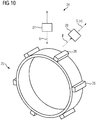
- FIG 7 shows a possible arrangement of the embodiment elements 26 in an unrolled illustration.
- a total of six embodiment elements 26 are present.
- this number is purely exemplary.
- the embodiment elements 26 are the embodiment elements 26 arranged evenly distributed around the axis of rotation 6 as seen. If k denotes the number of embodiment elements 26, the embodiment elements 26 are thus spaced from one another by 360 ° / k in the tangential direction. In the specific example of FIG 7 the embodiment elements 26 are thus spaced apart from one another by 60 ° in the tangential direction.
- FIG 8 shows one to FIG 7 alternative design.
- the embodiment elements 26 are arranged in an unevenly distributed manner as seen around the axis of rotation 6.
- one of the embodiment elements 26 can be arranged somewhat offset in the tangential direction, so that this one embodiment element 26 has an angular offset to its two adjacent embodiment elements 26 which is once greater and once less than 360 ° / k, with k again indicating the number Embodiment elements 26 is designated.
- the distance from one another is preferably 360 ° / k.
- the embodiment elements 26 can according to FIG 9 be raised. In this case it can be of advantage if the embodiment elements 26 spiral around the axis of rotation 6. As a result, the embodiment elements 26 can actively convey the air 15 through the electrical machine 1, possibly as support for the fan wheel 14.
- the design according to FIG 9 is however - at least as a rule - Only makes sense if the direction of rotation of the electrical machine 1 is always the same.
- the sensor 24 preferably works on a magnetic principle. Corresponding principles are generally known to those skilled in the art and therefore do not have to be explained in detail.
- the converter housing 17 should, however, consist of a non-magnetic material, for example a plastic, at least in the area between the sensor 24 and the measuring standard 25. This is in the FIG 5, 6 and 9 indicated by a corresponding hatching of the converter housing 17 in the corresponding area.
- the present invention thus relates to the following facts:
- a machine arrangement has an electrical machine 1 which has a rotor 2 and a stator 3.
- the rotor 2 is arranged non-rotatably on a rotor shaft 4 which can be rotated about an axis of rotation 6.
- the stator 3 has a stator winding system 7 which, at an axial end of the electrical machine 1, has machine-side connections 8 for supplying operating currents to the stator winding system 7.
- the machine arrangement also has a converter 9 which has connections 10 on the converter side.
- the machine-side connections 8 and the converter-side connections 10 are electrically connected to one another.
- the converter 9 is arranged at that axial end of the electrical machine 1 at which the stator winding system 7 has the connections 8 on the machine side.
Priority Applications (2)
| Application Number | Priority Date | Filing Date | Title |
|---|---|---|---|
| EP19170867.6A EP3731385A1 (fr) | 2019-04-24 | 2019-04-24 | Agencement améliorée d'une unité de convertisseur et de moteur |
| PCT/EP2020/056035 WO2020216515A1 (fr) | 2019-04-24 | 2020-03-06 | Amélioration de la disposition d'une unité convertissuer-moteur |
Applications Claiming Priority (1)
| Application Number | Priority Date | Filing Date | Title |
|---|---|---|---|
| EP19170867.6A EP3731385A1 (fr) | 2019-04-24 | 2019-04-24 | Agencement améliorée d'une unité de convertisseur et de moteur |
Publications (1)
| Publication Number | Publication Date |
|---|---|
| EP3731385A1 true EP3731385A1 (fr) | 2020-10-28 |
Family
ID=66251697
Family Applications (1)
| Application Number | Title | Priority Date | Filing Date |
|---|---|---|---|
| EP19170867.6A Withdrawn EP3731385A1 (fr) | 2019-04-24 | 2019-04-24 | Agencement améliorée d'une unité de convertisseur et de moteur |
Country Status (2)
| Country | Link |
|---|---|
| EP (1) | EP3731385A1 (fr) |
| WO (1) | WO2020216515A1 (fr) |
Citations (5)
| Publication number | Priority date | Publication date | Assignee | Title |
|---|---|---|---|---|
| EP0825703A2 (fr) * | 1996-08-23 | 1998-02-25 | Leopold Kostal GmbH & Co. KG | Moteur électrique |
| EP1511157A2 (fr) * | 2003-08-29 | 2005-03-02 | SEW-EURODRIVE GMBH & CO. | Moteur électrique et systeme de construction modulaire de moteurs électriques |
| DE102008000124A1 (de) * | 2008-01-22 | 2009-07-30 | Visteon Global Technologies, Inc., Van Buren Township | Kompressor, insbesondere elektromotorisch angetriebener Kompressor |
| WO2014127392A2 (fr) * | 2013-02-25 | 2014-08-28 | Atb Spielberg Gmbh | Machine électrique, notamment moteur |
| GB2538624A (en) * | 2015-05-05 | 2016-11-23 | Skf Ab | Power generator and railway bearing unit |
Family Cites Families (3)
| Publication number | Priority date | Publication date | Assignee | Title |
|---|---|---|---|---|
| US6011331A (en) * | 1997-04-22 | 2000-01-04 | Emerson Electric Co. | Electric motor having an improved airflow cooling system |
| WO2008104345A2 (fr) * | 2007-02-28 | 2008-09-04 | Sew-Eurodrive Gmbh & Co. Kg | Moteur électrique |
| DE102012206898A1 (de) * | 2012-04-26 | 2013-10-31 | Robert Bosch Gmbh | Elektrische Maschine |
-
2019
- 2019-04-24 EP EP19170867.6A patent/EP3731385A1/fr not_active Withdrawn
-
2020
- 2020-03-06 WO PCT/EP2020/056035 patent/WO2020216515A1/fr active Application Filing
Patent Citations (5)
| Publication number | Priority date | Publication date | Assignee | Title |
|---|---|---|---|---|
| EP0825703A2 (fr) * | 1996-08-23 | 1998-02-25 | Leopold Kostal GmbH & Co. KG | Moteur électrique |
| EP1511157A2 (fr) * | 2003-08-29 | 2005-03-02 | SEW-EURODRIVE GMBH & CO. | Moteur électrique et systeme de construction modulaire de moteurs électriques |
| DE102008000124A1 (de) * | 2008-01-22 | 2009-07-30 | Visteon Global Technologies, Inc., Van Buren Township | Kompressor, insbesondere elektromotorisch angetriebener Kompressor |
| WO2014127392A2 (fr) * | 2013-02-25 | 2014-08-28 | Atb Spielberg Gmbh | Machine électrique, notamment moteur |
| GB2538624A (en) * | 2015-05-05 | 2016-11-23 | Skf Ab | Power generator and railway bearing unit |
Also Published As
| Publication number | Publication date |
|---|---|
| WO2020216515A1 (fr) | 2020-10-29 |
Similar Documents
| Publication | Publication Date | Title |
|---|---|---|
| EP2639936B1 (fr) | Machine électrique à rotor excité en permanence et rotor excité en permanence correspondant | |
| DE102009001173B4 (de) | Bürstenloser Motor | |
| EP1456931A1 (fr) | Moteur a rotor interne | |
| DE102009000681A1 (de) | Synchronmaschine | |
| EP0052343A2 (fr) | Machine électrique | |
| DE2800886A1 (de) | Gleichstrommotor | |
| DE102014206342A1 (de) | Rotor für eine elektrische Maschine mit Einrichtung zur Feldschwächung sowie elektrische Maschine | |
| EP2427951B1 (fr) | Machine electrique synchrone | |
| WO2008098403A2 (fr) | Machine électrique | |
| DE102019112268A1 (de) | Synchronmotor | |
| DE102007034929A1 (de) | Transversalflussmaschine | |
| EP0094978B1 (fr) | Machine électrique rotative | |
| DE102013102124A1 (de) | Einphasiger Elektromotor | |
| EP2065690B1 (fr) | Machine dynamoélectrique dotée d'un système d'enregistrement de la température | |
| EP3731385A1 (fr) | Agencement améliorée d'une unité de convertisseur et de moteur | |
| DE102018215783A1 (de) | Positionserfassungssystem und Verfahren zur Erfassung einer Bewegung einer Maschine | |
| DE2914185A1 (de) | Generator mit permanentmagnet | |
| DE102006011738A1 (de) | Elektrische Maschine mit einem schnell drehenden Läufer | |
| DE1927795A1 (de) | Dynamo-elektrische Maschine mit einem permanent-magnetischen Stator | |
| EP2584671B1 (fr) | Machine électrique | |
| EP0216202B1 (fr) | Moteur électrique | |
| DE2460062A1 (de) | Elektrische maschine | |
| EP1158648B1 (fr) | Entrainement de rotation électromagnetique | |
| EP1443639A1 (fr) | Excitateur rotatif de grandes courants | |
| EP3057209B1 (fr) | Système d'entraînement sous forme d'un moteur à couple |
Legal Events
| Date | Code | Title | Description |
|---|---|---|---|
| PUAI | Public reference made under article 153(3) epc to a published international application that has entered the european phase |
Free format text: ORIGINAL CODE: 0009012 |
|
| STAA | Information on the status of an ep patent application or granted ep patent |
Free format text: STATUS: THE APPLICATION HAS BEEN PUBLISHED |
|
| AK | Designated contracting states |
Kind code of ref document: A1 Designated state(s): AL AT BE BG CH CY CZ DE DK EE ES FI FR GB GR HR HU IE IS IT LI LT LU LV MC MK MT NL NO PL PT RO RS SE SI SK SM TR |
|
| AX | Request for extension of the european patent |
Extension state: BA ME |
|
| STAA | Information on the status of an ep patent application or granted ep patent |
Free format text: STATUS: THE APPLICATION IS DEEMED TO BE WITHDRAWN |
|
| 18D | Application deemed to be withdrawn |
Effective date: 20210429 |