EP3731385A1 - Improved arrangement of a motor-inverter unit - Google Patents

Improved arrangement of a motor-inverter unit Download PDF

Info

Publication number
EP3731385A1
EP3731385A1 EP19170867.6A EP19170867A EP3731385A1 EP 3731385 A1 EP3731385 A1 EP 3731385A1 EP 19170867 A EP19170867 A EP 19170867A EP 3731385 A1 EP3731385 A1 EP 3731385A1
Authority
EP
European Patent Office
Prior art keywords
machine
converter
sensor
machine arrangement
arrangement according
Prior art date
Legal status (The legal status is an assumption and is not a legal conclusion. Google has not performed a legal analysis and makes no representation as to the accuracy of the status listed.)
Withdrawn
Application number
EP19170867.6A
Other languages
German (de)
French (fr)
Inventor
Christian Deeg
Harald Kuhn
Peter Köllensperger
Christian Maul
Hans Tischmacher
Current Assignee (The listed assignees may be inaccurate. Google has not performed a legal analysis and makes no representation or warranty as to the accuracy of the list.)
Siemens AG
Original Assignee
Siemens AG
Priority date (The priority date is an assumption and is not a legal conclusion. Google has not performed a legal analysis and makes no representation as to the accuracy of the date listed.)
Filing date
Publication date
Application filed by Siemens AG filed Critical Siemens AG
Priority to EP19170867.6A priority Critical patent/EP3731385A1/en
Priority to PCT/EP2020/056035 priority patent/WO2020216515A1/en
Publication of EP3731385A1 publication Critical patent/EP3731385A1/en
Withdrawn legal-status Critical Current

Links

Images

Classifications

    • HELECTRICITY
    • H02GENERATION; CONVERSION OR DISTRIBUTION OF ELECTRIC POWER
    • H02KDYNAMO-ELECTRIC MACHINES
    • H02K11/00Structural association of dynamo-electric machines with electric components or with devices for shielding, monitoring or protection
    • H02K11/30Structural association with control circuits or drive circuits
    • H02K11/33Drive circuits, e.g. power electronics
    • HELECTRICITY
    • H02GENERATION; CONVERSION OR DISTRIBUTION OF ELECTRIC POWER
    • H02KDYNAMO-ELECTRIC MACHINES
    • H02K11/00Structural association of dynamo-electric machines with electric components or with devices for shielding, monitoring or protection
    • H02K11/20Structural association of dynamo-electric machines with electric components or with devices for shielding, monitoring or protection for measuring, monitoring, testing, protecting or switching
    • H02K11/21Devices for sensing speed or position, or actuated thereby
    • HELECTRICITY
    • H02GENERATION; CONVERSION OR DISTRIBUTION OF ELECTRIC POWER
    • H02KDYNAMO-ELECTRIC MACHINES
    • H02K9/00Arrangements for cooling or ventilating
    • H02K9/02Arrangements for cooling or ventilating by ambient air flowing through the machine
    • H02K9/04Arrangements for cooling or ventilating by ambient air flowing through the machine having means for generating a flow of cooling medium
    • H02K9/06Arrangements for cooling or ventilating by ambient air flowing through the machine having means for generating a flow of cooling medium with fans or impellers driven by the machine shaft
    • HELECTRICITY
    • H02GENERATION; CONVERSION OR DISTRIBUTION OF ELECTRIC POWER
    • H02KDYNAMO-ELECTRIC MACHINES
    • H02K3/00Details of windings
    • H02K3/46Fastening of windings on the stator or rotor structure
    • H02K3/50Fastening of winding heads, equalising connectors, or connections thereto

Abstract

Eine Maschinenanordnung weist eine elektrische Maschine (1) auf, die einen Rotor (2) und einen Stator (3) aufweist. Der Rotor (2) ist drehfest auf einer Rotorwelle (4) angeordnet, die um eine Rotationsachse (6) rotierbar ist. Der Stator (3) weist ein Statorwicklungssystem (7) auf, das an einem axialen Ende der elektrischen Maschine (1) maschinenseitige Anschlüsse (8) zum Zuführen von Betriebsströmen zum Statorwicklungssystem (7) aufweist. Die Maschinenanordnung weist weiterhin einen Umrichter (9) auf, der umrichterseitige Anschlüsse (10) aufweist. Die maschinenseitigen Anschlüsse (8) und die umrichterseitigen Anschlüsse (10) sind elektrisch miteinander verbunden. Der Umrichter (9) ist an demjenigen axialen Ende der elektrischen Maschine (1) angeordnet, an dem das Statorwicklungssystem (7) die maschinenseitigen Anschlüsse (8) aufweist.A machine arrangement has an electrical machine (1) which has a rotor (2) and a stator (3). The rotor (2) is non-rotatably arranged on a rotor shaft (4) which can be rotated about an axis of rotation (6). The stator (3) has a stator winding system (7) which, at one axial end of the electrical machine (1), has machine-side connections (8) for supplying operating currents to the stator winding system (7). The machine arrangement also has a converter (9) which has connections (10) on the converter side. The machine-side connections (8) and the converter-side connections (10) are electrically connected to one another. The converter (9) is arranged at that axial end of the electrical machine (1) at which the stator winding system (7) has the machine-side connections (8).

Description

Die vorliegende Erfindung geht aus von einer Maschinenanordnung,

  • wobei die Maschinenanordnung eine elektrische Maschine aufweist,
  • wobei die elektrische Maschine einen Rotor und einen Stator aufweist,
  • wobei der Rotor drehfest auf einer Rotorwelle angeordnet ist und die Rotorwelle um eine Rotationsachse rotierbar ist,
  • wobei der Stator ein Statorwicklungssystem aufweist,
  • wobei das Statorwicklungssystem an einem axialen Ende der elektrischen Maschine maschinenseitige Anschlüsse zum Zuführen von Betriebsströmen zum Statorwicklungssystem aufweist,
  • wobei die Maschinenanordnung einen Umrichter aufweist, der umrichterseitige Anschlüsse aufweist,
  • wobei die maschinenseitigen Anschlüsse und die umrichterseitigen Anschlüsse elektrisch miteinander verbunden sind.
The present invention is based on a machine arrangement,
  • wherein the machine arrangement comprises an electrical machine,
  • wherein the electrical machine has a rotor and a stator,
  • wherein the rotor is arranged non-rotatably on a rotor shaft and the rotor shaft is rotatable about an axis of rotation,
  • wherein the stator has a stator winding system,
  • wherein the stator winding system has machine-side connections for supplying operating currents to the stator winding system at one axial end of the electrical machine,
  • wherein the machine arrangement has a converter which has converter-side connections,
  • wherein the machine-side connections and the converter-side connections are electrically connected to one another.

Derartige Maschinenanordnungen sind allgemein bekannt.Such machine arrangements are generally known.

Umrichtergespeiste und damit drehzahlveränderbar betreibbare elektrische Maschinen finden immer größere Verbreitung. Der Vorteil der Möglichkeit, die Drehzahl der elektrischen Maschine zu verändern, besteht insbesondere in einer verbesserten Prozesssteuerung und einer besseren Energieeffizienz. Beispielsweise kann bei einer Anwendung zum Treiben einer Pumpe eine verlustreiche Steuerung einer Drosselklappe durch eine entsprechende Anpassung der Drehzahl der elektrischen Maschine ersetzt werden.Converter-fed electrical machines that can be operated with variable speeds are becoming increasingly popular. The advantage of being able to change the speed of the electrical machine is, in particular, improved process control and better energy efficiency. For example, in an application for driving a pump, a lossy control of a throttle valve can be replaced by a corresponding adjustment of the speed of the electrical machine.

In der Regel sind der Umrichter und die elektrische Maschine räumlich getrennte Einheiten. Die Energieübertragung vom Umrichter zur elektrischen Maschine erfolgt über eine entsprechende Verkabelung. Bei niedrigen und mittleren Leistungen bis ca. 100kW ist es auch schon bekannt, den Umrichter direkt an der elektrischen Maschine anzuordnen. Die elektrische Maschine und der Umrichter bilden somit eine Baueinheit, bei der die Leistungsverkabelung integriert ist und das Gesamtsystem gut aufeinander abgestimmt werden kann. Der Endanwender erhält eine drehzahlveränderbare Antriebseinheit, die er nur noch mit dem Versorgungsnetz verbinden muss.As a rule, the converter and the electrical machine are spatially separate units. The energy transfer from the converter to the electrical machine takes place via a corresponding one Cabling. In the case of low and medium powers up to approx. 100kW, it is already known to arrange the converter directly on the electrical machine. The electrical machine and the converter thus form a unit in which the power cabling is integrated and the overall system can be well coordinated. The end user receives a variable-speed drive unit that he only has to connect to the supply network.

Im Falle einer derartigen Baueinheit wird der Umrichter in der Regel auf den Klemmenkasten aufgesetzt oder im Klemmenkasten angeordnet. Der Klemmenkasten ist eine Einheit, die - bei waagrechter Orientierung der Rotationsachse - in der Regel oben auf die elektrische Maschine aufgesetzt ist. Dadurch muss innerhalb der elektrischen Maschine immer noch eine relativ lange Verkabelung umständlich vom Klemmenkasten zu demjenigen axialen Ende der elektrischen Maschine geführt werden, an dem das Statorwicklungssystem die maschinenseitigen Anschlüsse aufweist.In the case of such a structural unit, the converter is usually placed on the terminal box or arranged in the terminal box. The terminal box is a unit which - when the axis of rotation is horizontal - is usually placed on top of the electrical machine. As a result, a relatively long cabling still has to be laboriously routed within the electrical machine from the terminal box to that axial end of the electrical machine at which the stator winding system has the machine-side connections.

Die Aufgabe der vorliegenden Erfindung besteht darin, eine verbesserte und vereinfachte Maschinenanordnung zu schaffen, bei der das umständliche Führen der Verkabelung vom Klemmenkasten zu demjenigen axialen Ende der elektrischen Maschine, an dem das Statorwicklungssystem die maschinenseitigen Anschlüsse aufweist, entfallen kann.The object of the present invention is to create an improved and simplified machine arrangement in which the cumbersome routing of the cabling from the terminal box to that axial end of the electrical machine at which the stator winding system has the machine-side connections can be dispensed with.

Die Aufgabe wird durch eine Maschinenanordnung mit den Merkmalen des Anspruchs 1 gelöst. Vorteilhafte Ausgestaltungen der Maschinenanordnung sind Gegenstand der abhängigen Ansprüche 2 bis 14.The object is achieved by a machine arrangement with the features of claim 1. Advantageous configurations of the machine arrangement are the subject matter of the dependent claims 2 to 14.

Erfindungsgemäß wird eine Maschinenanordnung der eingangs genannten Art dadurch ausgestaltet, dass der Umrichter an demjenigen axialen Ende der elektrischen Maschine angeordnet ist, an dem das Statorwicklungssystem die maschinenseitigen Anschlüsse aufweist.According to the invention, a machine arrangement of the type mentioned at the outset is designed in that the converter is arranged at that axial end of the electrical machine at which the stator winding system has the machine-side connections.

Der Begriff "an demjenigen axialen Ende der elektrischen Maschine angeordnet ist, an dem das Statorwicklungssystem die maschinenseitigen Anschlüsse aufweist" soll hierbei nicht bedeuten, dass der Umrichter "mit Luft" an dem entsprechenden axialen Ende angeordnet ist. Vielmehr soll der Begriff bedeuten, dass entweder der Umrichter direkt an das entsprechende axiale Ende der elektrischen Maschine angrenzt oder - falls zwischen dem entsprechenden axialen Ende der elektrischen Maschine und dem Umrichter ausnahmsweise ein weiteres Element der Maschinenanordnung angeordnet ist - der Umrichter direkt an dieses weitere Element angrenzt und das weitere Element der Maschinenanordnung direkt an das entsprechende axiale Ende der elektrischen Maschine angrenzt.The term "is arranged at that axial end of the electrical machine at which the stator winding system has the machine-side connections" is not intended to mean that the converter is arranged "with air" at the corresponding axial end. Rather, the term is intended to mean that either the converter is directly adjacent to the corresponding axial end of the electrical machine or - if a further element of the machine arrangement is exceptionally arranged between the corresponding axial end of the electrical machine and the converter - the converter is directly adjacent to this further element and the other element of the machine arrangement is directly adjacent to the corresponding axial end of the electrical machine.

Weiterhin bezeichnet der Begriff "Umrichter" diejenige Einheit, welche die elektronischen Schaltelemente aufweist, welche die dem Statorwicklungssystem zugeführten Betriebsströme schalten. Vorzugsweise weist diese Einheit auch den elektronischen Schaltelementen vorgeordnete Elemente auf, beispielsweise Kondensatorelemente und/oder Gleichrichterelemente. Zwingend ist dies aber nicht erforderlich. Zwingend sind nur die elektronischen Schaltelemente vorhanden.Furthermore, the term “converter” denotes that unit which has the electronic switching elements which switch the operating currents supplied to the stator winding system. This unit preferably also has elements arranged upstream of the electronic switching elements, for example capacitor elements and / or rectifier elements. However, this is not absolutely necessary. Only the electronic switching elements are mandatory.

Durch diese Gestaltung wird erreicht, dass Verbindungsleitungen von den umrichterseitigen Anschlüssen zu den maschinenseitigen Anschlüssen sehr kurz und einfach geführt werden können.This design ensures that connecting lines from the converter-side connections to the machine-side connections can be run very short and easily.

In aller Regel sind die maschinenseitigen Anschlüsse gleichmäßig um die Rotationsachse herum verteilt angeordnet und sind weiterhin auch die umrichterseitigen Anschlüsse gleichmäßig um die Rotationsachse herum verteilt angeordnet. Dadurch kann eine 1:1-Verbindung mit vollständig oder zumindest nahezu rein axial verlaufenden Verbindungsleitungen erfolgen.As a rule, the machine-side connections are arranged evenly distributed around the axis of rotation and, furthermore, the converter-side connections are also arranged evenly distributed around the axis of rotation. As a result, a 1: 1 connection can be made with connection lines running completely or at least almost purely axially.

Vorzugsweise weist der Umrichter eine Mittenausnehmung für den Durchtritt der Rotorwelle auf. Dadurch behindert der Umrichter nicht die Rotorwelle.The converter preferably has a central recess for the rotor shaft to pass through. This means that the converter does not obstruct the rotor shaft.

Die elektrische Maschine kann nach Bedarf ausgebildet sein. Vorzugsweise ist sie jedoch als permanenterregte Synchronmaschine, als Induktionsmaschine oder als Reluktanzmaschine ausgebildet.The electrical machine can be designed as required. However, it is preferably designed as a permanently excited synchronous machine, as an induction machine or as a reluctance machine.

In vielen Fällen weist die Maschinenanordnung einen Lüfter mit einem Lüfterrad auf. In diesem Fall ist vorzugsweise der Lüfter ebenfalls an demjenigen axialen Ende der elektrischen Maschine angeordnet, an dem das Statorwicklungssystem die maschinenseitigen Anschlüsse aufweist. Der Lüfter kann - im Einzelfall - ein weiteres Element der Maschinenanordnung sein, das zwischen dem Umrichter und der elektrischen Maschine angeordnet ist. In der Regel ist jedoch umgekehrt der Umrichter zwischen der elektrischen Maschine und dem Lüfter angeordnet. In beiden Fällen grenzen die elektrische Maschine, der Umrichter und der Lüfter in Richtung der Rotationsachse gesehen jedoch unmittelbar aneinander an.In many cases, the machine arrangement has a fan with a fan wheel. In this case, the fan is preferably also arranged at that axial end of the electrical machine at which the stator winding system has the machine-side connections. The fan can - in individual cases - be a further element of the machine arrangement which is arranged between the converter and the electrical machine. As a rule, however, the converter is arranged in reverse between the electrical machine and the fan. In both cases, however, the electrical machine, the converter and the fan, viewed in the direction of the axis of rotation, are directly adjacent to one another.

Falls ein Lüfter mit einem Lüfterrad vorhanden ist, ist es möglich,

  • dass die Maschinenanordnung einen Sensor und eine von dem Sensor abgetastete Maßverkörperung aufweist, so dass aufgrund eines von dem Sensor abgegebenen Sensorsignals eine Drehzahl der Rotorwelle ermittelbar ist,
  • dass der Umrichter eine Umrichterschaltung und ein Umrichtergehäuse aufweist,
  • dass sowohl die Umrichterschaltung als auch der Sensor im Umrichtergehäuse angeordnet sind,
  • dass das Lüfterrad drehfest mit der Rotorwelle verbunden ist und
  • dass die Maßverkörperung auf dem Lüfterrad angeordnet ist.
If there is a fan with a fan wheel, it is possible to
  • that the machine arrangement has a sensor and a material measure scanned by the sensor so that a speed of the rotor shaft can be determined on the basis of a sensor signal emitted by the sensor,
  • that the converter has a converter circuit and a converter housing,
  • that both the converter circuit and the sensor are arranged in the converter housing,
  • that the fan wheel is rotatably connected to the rotor shaft and
  • that the material measure is arranged on the fan wheel.

Dadurch kann auf relativ einfache Weise die Drehzahl der Rotorwelle ermittelt werden. Hierbei ist es möglich, dass mittels des Sensors die Drehzahl selbst erfasst wird. Es ist auch möglich, dass mittels des Sensors die Drehstellung erfasst wird und daraus durch zeitliche Ableitung die Drehzahl ermittelt wird.As a result, the speed of the rotor shaft can be determined in a relatively simple manner. It is possible that by means of of the sensor the speed itself is recorded. It is also possible for the rotary position to be detected by means of the sensor and for the rotational speed to be determined therefrom by deriving it over time.

Alternativ ist es möglich,

  • dass die Maschinenanordnung einen Sensor und eine von dem Sensor abgetastete Maßverkörperung aufweist, so dass aufgrund eines von dem Sensor abgegebenen Sensorsignals zumindest eine Drehzahl der Rotorwelle ermittelbar ist,
  • dass der Umrichter eine Umrichterschaltung und ein Umrichtergehäuse aufweist,
  • dass sowohl die Umrichterschaltung als auch der Sensor im Umrichtergehäuse angeordnet sind und
  • dass die Maßverkörperung auf der Rotorwelle angeordnet ist.
Alternatively it is possible
  • that the machine arrangement has a sensor and a material measure scanned by the sensor, so that at least one speed of the rotor shaft can be determined on the basis of a sensor signal emitted by the sensor,
  • that the converter has a converter circuit and a converter housing,
  • that both the converter circuit and the sensor are arranged in the converter housing and
  • that the material measure is arranged on the rotor shaft.

Diese Ausgestaltung ist im Unterschied zur Anordnung der Maßverkörperung auf dem Lüfterrad unabhängig davon realisierbar, ob das Lüfterrad vorhanden ist oder nicht. Im übrigen gelten die Ausführungen, die obenstehend in Verbindung mit einer Anordnung der Maßverkörperung auf dem Lüfterrad getroffen sind.In contrast to the arrangement of the material measure on the fan wheel, this configuration can be implemented regardless of whether the fan wheel is present or not. Otherwise, the statements made above in connection with an arrangement of the material measure on the fan wheel apply.

In der Regel weist die Maßverkörperung um die Rotationsachse herum gesehen mehrere Verkörperungselemente auf. In diesem Fall ist es möglich, dass die Verkörperungselemente erhaben ausgebildet sind und spiralförmig um die Rotationsachse umlaufen. Dadurch können die Verkörperungselemente insbesondere in dem Fall, dass die Drehrichtung der elektrischen Maschine stets dieselbe ist, derart um die Rotationsachse umlaufen, dass sie den Luftstrom aktiv zur elektrischen Maschine fördern bzw. einen derartigen Luftstrom unterstützen.As a rule, the material measure has a plurality of embodiment elements as seen around the axis of rotation. In this case, it is possible for the embodiment elements to be raised and to revolve in a spiral around the axis of rotation. As a result, particularly in the event that the direction of rotation of the electrical machine is always the same, the embodiment elements can revolve around the axis of rotation in such a way that they actively promote the air flow to the electrical machine or support such an air flow.

Die Maßverkörperung weist um die Rotationsachse herum gesehen mehrere Verkörperungselemente. Hierbei ist es alternativ möglich, dass die Verkörperungselemente um die Rotationsachse herum gesehen gleichmäßig oder ungleichmäßig verteilt angeordnet sind. Im Falle einer gleichmäßigen Verteilung ist eine besonders stabile Erkennung der Drehzahl möglich. Im Falle einer ungleichmäßigen Verteilung ist - zusätzlich zur betragsmäßigen Erkennung der Drehzahl - eine Erkennung der Drehrichtung des Rotors möglich.The material measure has several embodiment elements as seen around the axis of rotation. It is alternatively possible here for the embodiment elements to be arranged distributed uniformly or non-uniformly as seen around the axis of rotation. In the case of an even distribution, a particularly stable detection of the speed is possible. In the event of In the event of an uneven distribution, it is possible to detect the direction of rotation of the rotor in addition to the detection of the absolute value of the speed.

Vorzugsweise ist der Sensor als nach einem magnetischen Prinzip arbeitender Sensor ausgebildet. Ein nach einem magnetischen Prinzip arbeitender Sensor ist bevorzugt, weil er gegenüber Verschmutzungen und dergleichen erheblich unempfindlicher ist als ein nach einem optischen Prinzip arbeitender Sensor. In diesem Fall besteht das Umrichtergehäuse vorzugsweise zumindest im Bereich zwischen dem Sensor und der Maßverkörperung aus einem unmagnetischen Material. Ein unmagnetisches Material im Sinne der vorliegenden Erfindung ist ein diamagnetisches Material. Diamagnetische Materialien sind allgemein bekannt. Ein Beispiel eines geeigneten Materials ist ein Kunststoff.The sensor is preferably designed as a sensor that operates on a magnetic principle. A sensor that works according to a magnetic principle is preferred because it is considerably less sensitive to contamination and the like than a sensor that works according to an optical principle. In this case, the converter housing is preferably made of a non-magnetic material at least in the area between the sensor and the material measure. A non-magnetic material in the context of the present invention is a diamagnetic material. Diamagnetic materials are well known. An example of a suitable material is a plastic.

Es ist möglich, dass die Maßverkörperung aus einem permanentmagnetischen Material besteht, das von dem Sensor abgetastet wird. Vorzugsweise ist jedoch vorgesehen,

  • dass der Sensor ein Anregungselement und ein Empfangselement aufweist,
  • dass die Maßverkörperung aus einem magnetisierbaren, aber nicht permanentmagnetischen Material besteht,
  • dass die Maßverkörperung mittels des Anregungselementes magnetisiert wird,
  • dass mittels des Empfangselements ein Empfangssignal empfangen wird und
  • dass das Empfangselement das Sensorsignal anhand des Empfangssignals ermittelt.
It is possible that the measuring standard consists of a permanent magnetic material that is scanned by the sensor. However, it is preferably provided
  • that the sensor has an excitation element and a receiving element,
  • that the measuring standard consists of a magnetizable, but not permanently magnetic material,
  • that the measuring standard is magnetized by means of the excitation element,
  • that a received signal is received by means of the receiving element and
  • that the receiving element determines the sensor signal based on the received signal.

Die oben beschriebenen Eigenschaften, Merkmale und Vorteile dieser Erfindung sowie die Art und Weise, wie diese erreicht werden, werden klarer und deutlicher verständlich im Zusammenhang mit der folgenden Beschreibung der Ausführungsbeispiele, die in Verbindung mit den Zeichnungen näher erläutert werden. Hierbei zeigen in schematischer Darstellung:

FIG 1
eine Seitenansicht einer Maschinenanordnung,
FIG 2
einen Längsschnitt durch die Maschinenanordnung von FIG 1,
FIG 3
einen Schnitt längs einer Linie III-III in FIG 2,
FIG 4
eine schematische Draufsicht auf ein Anschlussende,
FIG 5
einen Teil des Längsschnitts von FIG 2,
FIG 6
eine zu FIG 5 alternative Ausgestaltung,
FIG 7
eine mögliche Anordnung von Verkörperungselementen einer Maßverkörperung,
FIG 8
eine zu FIG 7 alternative Anordnung der Verkörperungselemente,
FIG 9
eine mögliche Ausgestaltung von
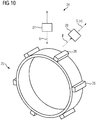
 FIG 6 und
FIG 10
einen Sensor und eine Maßverkörperung.
The above-described properties, features and advantages of this invention as well as the manner in which they are achieved will become more clearly and clearly understood in connection with the following description of the exemplary embodiments, which are explained in more detail in connection with the drawings. Here show in a schematic representation:
FIG 1
a side view of a machine arrangement,
FIG 2
a longitudinal section through the machine arrangement of FIG 1 ,
FIG 3
a section along a line III-III in FIG 2 ,
FIG 4
a schematic top view of a connection end,
FIG 5
part of the longitudinal section of FIG 2 ,
FIG 6
one to FIG 5 alternative design,
FIG 7
a possible arrangement of embodiment elements of a material measure,
FIG 8
one to FIG 7 alternative arrangement of the embodiment elements,
FIG 9
a possible design of FIG 6 and
FIG 10
a sensor and a material measure.

Gemäß den FIG 1 und 2 weist eine Maschinenanordnung zumindest eine elektrische Maschine 1 auf. Die elektrische Maschine 1 ist als rotatorische elektrische Maschine ausgebildet. Sie weist also einen Rotor 2 und einen Stator 3 auf. Der Rotor 2 ist drehfest auf einer Rotorwelle 4 angeordnet. Die Rotorwelle 4 ist in Lagern 5 gelagert und dadurch um eine Rotationsachse 6 rotierbar. Zusammen mit der Rotorwelle 4 rotiert auch der Rotor 2, und zwar jeweils um den gleichen Drehwinkel wie die Rotorwelle 4. Die Bauart der elektrischen Maschine 1 kann nach Bedarf sein. Vorzugsweise ist die elektrische Maschine 1 als permanenterregte Synchronmaschine, als Induktionsmaschine oder als Reluktanzmaschine ausgebildet.According to the FIGS. 1 and 2 a machine arrangement has at least one electrical machine 1. The electrical machine 1 is designed as a rotary electrical machine. It therefore has a rotor 2 and a stator 3. The rotor 2 is arranged non-rotatably on a rotor shaft 4. The rotor shaft 4 is supported in bearings 5 and is thus rotatable about an axis of rotation 6. The rotor 2 also rotates together with the rotor shaft 4, to be precise in each case by the same angle of rotation as the rotor shaft 4. The design of the electrical machine 1 can be as required. The electrical machine 1 is preferably designed as a permanently excited synchronous machine, as an induction machine or as a reluctance machine.

Soweit nachfolgend die Begriffe "axial", "radial" und "tangential" verwendet werden, sind sie stets auf die Rotationsachse 6 bezogen. "Axial" bezeichnet eine Richtung parallel zur Rotationsachse 6. "Radial" bezeichnet eine Richtung in einer orthogonal zur Rotationsachse 6 orientierten Ebene direkt auf die Rotationsachse 6 zu oder von ihr weg. "Tangential" bezeichnet eine Richtung, die innerhalb der orthogonal zur Rotationsachse 6 orientierten Ebene orthogonal zur Radialrichtung orientiert ist. "Tangential" bezeichnet also eine Richtung, die bei einer konstanten Axialposition in einem konstanten radialen Abstand von der Rotationsachse 6 kreisförmig um die Rotationsachse 6 herum gerichtet ist.To the extent that the terms “axial”, “radial” and “tangential” are used below, they are always related to the axis of rotation 6. “Axial” denotes a direction parallel to the axis of rotation 6. “Radial” denotes a direction in a plane oriented orthogonally to the axis of rotation 6 directly towards or away from the axis of rotation 6. “Tangential” denotes a direction which is oriented orthogonally to the radial direction within the plane oriented orthogonally to the axis of rotation 6. "Tangential" means a direction that is at a constant axial position in a constant radial distance from the axis of rotation 6 is directed circularly around the axis of rotation 6.

Der Stator 3 weist ein Statorwicklungssystem 7 auf. Das Statorwicklungssystem 7 ist in Nuten des Stators 3 angeordnet. Die Nuten sind in den FIG nicht dargestellt. Vom Statorwicklungssystem 7 sind in FIG 2 nur die beiden Wicklungsköpfe an den beiden axialen Enden der elektrischen Maschine 1 erkennbar.The stator 3 has a stator winding system 7. The stator winding system 7 is arranged in slots in the stator 3. The grooves are not shown in the FIG. From the stator winding system 7 are in FIG 2 only the two winding heads at the two axial ends of the electrical machine 1 can be seen.

Das Statorwicklungssystem 7 weist an einem axialen Ende der elektrischen Maschine 1 maschinenseitige Anschlüsse 8 auf. Die maschinenseitigen Anschlüsse 8 dienen dem Zuführen von Betriebsströmen zum Statorwicklungssystem 7. Das entsprechende axiale Ende, also das axiale Ende, an dem das Statorwicklungssystem 7 die maschinenseitigen Anschlüsse 8 aufweist, wird nachstehend als Anschlussende bezeichnet.The stator winding system 7 has connections 8 on the machine side at one axial end of the electrical machine 1. The machine-side connections 8 serve to supply operating currents to the stator winding system 7. The corresponding axial end, that is to say the axial end at which the stator winding system 7 has the machine-side connections 8, is referred to below as the connection end.

Gemäß den FIG 1 und 2 weist die Maschinenanordnung weiterhin einen Umrichter 9 auf. Der Umrichter 9 weist umrichterseitige Anschlüsse 10 auf. Die umrichterseitigen Anschlüsse 10 und die maschinenseitigen Anschlüsse 8 sind elektrisch miteinander verbunden, beispielsweise über Verbindungsleitungen 11. Die Betriebsströme werden den maschinenseitigen Anschlüssen 8 somit über die umrichterseitigen Anschlüsse 10 zugeführt. Der Umrichter 9 weist weiterhin Versorgungsanschlüsse 12 auf. Mittels der Versorgungsanschlüsse 12 kann dem Umrichter 9 - beispielsweise aus einem Versorgungsnetz - elektrische Energie zugeführt werden. Das Versorgungsnetz ist in den FIG nicht mit dargestellt, da die Art und Weise, auf welche der Umrichter 9 mit elektrischer Energie versorgt wird, im Rahmen der vorliegenden Erfindung von untergeordneter Bedeutung ist. Entscheidend ist hingegen, dass der Umrichter 9 am Anschlussende der elektrischen Maschine 1 angeordnet ist. Der Umrichter 9 kann am Anschlussende der elektrischen Maschine 1 insbesondere über Verbindungselemente befestigt sein, beispielsweise über gestrichelt angedeutete Schraubbolzen.According to the FIGS. 1 and 2 the machine arrangement also has a converter 9. The converter 9 has connections 10 on the converter side. The connections 10 on the converter side and the connections 8 on the machine side are electrically connected to one another, for example via connecting lines 11. The operating currents are thus fed to the connections 8 on the machine side via the connections 10 on the converter side. The converter 9 also has supply connections 12. By means of the supply connections 12, electrical energy can be supplied to the converter 9, for example from a supply network. The supply network is not shown in the figures, since the way in which the converter 9 is supplied with electrical energy is of secondary importance in the context of the present invention. What is decisive, however, is that the converter 9 is arranged at the connection end of the electrical machine 1. The converter 9 can be fastened to the connection end of the electrical machine 1, in particular via connecting elements, for example via screw bolts indicated by dashed lines.

In vielen Fällen weist die Maschinenanordnung zusätzlich zur elektrischen Maschine 1 und zum Umrichter 9 einen Lüfter 13 auf. Der Lüfter 13 weist seinerseits ein Lüfterrad 14 auf, mittels dessen Luft 15 zumindest durch die elektrische Maschine 1, meist auch durch den Umrichter 9 gefördert wird. Wenn der Lüfter 13 vorhanden ist, ist der Lüfter 13 in der Regel ebenfalls am Anschlussende der elektrischen Maschine 1 angeordnet. Vorzugsweise ist in diesem Fall entsprechend der Darstellung in den FIG 1 und 2 der Umrichter 9 zwischen der elektrischen Maschine 1 und dem Lüfter 13 angeordnet. In Einzelfällen kann aber auch der Lüfter 13 zwischen der elektrischen Maschine 1 und dem Umrichter 9 angeordnet sein. Auch hier ist beispielsweise wieder eine Schraubverbindung möglich (nicht dargestellt). Das Lüfterrad 14 kann mit der Rotorwelle 4 drehfest verbunden sein. Es sind jedoch auch Ausgestaltungen möglich, bei denen das Lüfterrad 14 mittels eines eigenen Antriebs unabhängig von dem Rotor 2 und der Rotorwelle 4 der elektrischen Maschine 1 rotiert wird.In many cases, the machine arrangement has a fan 13 in addition to the electrical machine 1 and the converter 9. The fan 13 for its part has a fan wheel 14, by means of which air 15 is conveyed at least through the electrical machine 1, mostly also through the converter 9. If the fan 13 is present, the fan 13 is generally also arranged at the connection end of the electrical machine 1. In this case, according to the illustration in FIGS FIGS. 1 and 2 the converter 9 is arranged between the electrical machine 1 and the fan 13. In individual cases, however, the fan 13 can also be arranged between the electrical machine 1 and the converter 9. A screw connection is also possible here, for example (not shown). The fan wheel 14 can be connected non-rotatably to the rotor shaft 4. However, configurations are also possible in which the fan wheel 14 is rotated by means of its own drive independently of the rotor 2 and the rotor shaft 4 of the electrical machine 1.

Der Umrichter 9 weist entsprechend der Darstellung in FIG 2 eine Umrichterschaltung 16 und ein Umrichtergehäuse 17 auf. Die Umrichterschaltung 16 ist im Umrichtergehäuse 17 angeordnet. Die Umrichterschaltung 16 umfasst entsprechend der Darstellung in FIG 3 in der Regel einen Schaltungsträger 18, auf dem die elektrisch wirksamen Komponenten des Umrichters 9 angeordnet sind, beispielsweise elektronische Schaltelemente 19, Gleichrichterelemente 20 und Kondensatorelemente 21. Die Elemente 19, 20 und 21 sind über elektrische Leitungen 22 miteinander verbunden. Von den elektrischen Leitungen 22 sind in FIG 3 nur einige wenige rein exemplarisch mit ihrem Bezugszeichen versehen. Die elektrischen Leitungen 22 können beispielsweise als auf dem Schaltungsträger 18 angeordnete Leiterbahnen ausgebildet sein. Auch die umrichterseitigen Anschlüsse 10 und die Versorgungsanschlüsse 12 können Bestandteile der Umrichterschaltung 16 sein. Der elektrotechnische Aufbau des Umrichters 9, die Verschaltung der einzelnen Komponenten des Umrichters 9 und der Betrieb des Umrichters 9 sind Fachleuten wohl bekannt und müssen daher nicht im Detail erläutert werden.The converter 9 has, as shown in FIG FIG 2 a converter circuit 16 and a converter housing 17. The converter circuit 16 is arranged in the converter housing 17. The converter circuit 16 comprises, as shown in FIG FIG 3 usually a circuit carrier 18 on which the electrically active components of the converter 9 are arranged, for example electronic switching elements 19, rectifier elements 20 and capacitor elements 21. The elements 19, 20 and 21 are connected to one another via electrical lines 22. Of the electrical lines 22 are in FIG 3 only a few are provided with their reference symbols purely by way of example. The electrical lines 22 can be designed, for example, as conductor tracks arranged on the circuit carrier 18. The converter-side connections 10 and the supply connections 12 can also be components of the converter circuit 16. The electrotechnical structure of the converter 9, the interconnection of the individual components of the converter 9 and the operation of the converter 9 are well known to those skilled in the art and therefore need not be explained in detail.

Entsprechend der Darstellung in FIG 3 sind auf dem Schaltungsträger 18 nicht nur die elektronischen Schaltelemente 19 selbst angeordnet, welche die dem Statorwicklungssystem 7 zugeführten Betriebsströme schalten, sondern zusätzlich auch die vorgeordneten Kondensatorelemente 21 und die diesen vorgeordneten Gleichrichterelemente 20. Es wäre aber auch möglich, die Gleichrichterelemente 20 oder die Gleichrichterelemente 20 und die Kondensatorelemente 21 außerhalb des Umrichters anzuordnen, beispielsweise in einem Klemmenkasten (nicht dargestellt). Als Umrichter 9 im Sinne der vorliegenden Erfindung wird also diejenige Einheit bezeichnet, welche die elektronischen Schaltelemente 19 aufweist, welche die dem Statorwicklungssystem 7 zugeführten Betriebsströme schalten. Vorzugsweise weist diese Einheit auch die Kondensatorelemente 21 und besonders vorzugsweise weiterhin auch die Gleichrichterelemente 20 auf. Zwingend ist dies aber nicht erforderlich.According to the representation in FIG 3 Not only are the electronic switching elements 19 themselves arranged on the circuit carrier 18, which switch the operating currents fed to the stator winding system 7, but also the upstream capacitor elements 21 and the rectifier elements 20 upstream of them and to arrange the capacitor elements 21 outside the converter, for example in a terminal box (not shown). The converter 9 in the sense of the present invention is that unit which has the electronic switching elements 19 which switch the operating currents supplied to the stator winding system 7. This unit preferably also has the capacitor elements 21 and particularly preferably also the rectifier elements 20. However, this is not absolutely necessary.

Vorzugsweise sind entsprechend der Darstellung in FIG 3 die umrichterseitigen Anschlüsse 10 gleichmäßig um die Rotationsachse 6 herum verteilt angeordnet. Insbesondere in dem typischen Fall, dass das Statorwicklungssystem 7 dreiphasig ausgebildet ist, sind entsprechend der Darstellung in FIG 3 drei umrichterseitige Anschlüsse 10 vorhanden, die bezüglich der Rotationsachse 6 jeweils um 120° versetzt angeordnet sind. Ein radialer Abstand der umrichterseitigen Anschlüsse 10 von der Rotationsachse 6 ist in der Regel einheitlich für alle umrichterseitigen Anschlüsse 10 derselbe.Preferably, as shown in FIG 3 the converter-side connections 10 are arranged distributed uniformly around the axis of rotation 6. In particular in the typical case that the stator winding system 7 has a three-phase design, according to the illustration in FIG FIG 3 There are three converter-side connections 10 which are arranged offset by 120 ° with respect to the axis of rotation 6. A radial distance between the connections 10 on the converter side and the axis of rotation 6 is generally the same for all connections 10 on the converter side.

Entsprechend der Darstellung in FIG 4 sind vorzugsweise auch die maschinenseitigen Anschlüsse 8 gleichmäßig um die Rotationsachse 6 herum verteilt angeordnet. Insbesondere stimmt die Anzahl an maschinenseitigen Anschlüssen 8 vorzugsweise 1:1 mit der Anzahl an umrichterseitigen Anschlüssen 10 überein. Es ist daher eine 1:1-Verbindung der maschinenseitigen Anschlüsse 8 mit den umrichterseitigen Anschlüssen 10 möglich. Weiterhin ist ein radialer Abstand der maschinenseitigen Anschlüsse 8 von der Rotationsachse 6 vorzugsweise einheitlich für alle maschinenseitigen Anschlüsse 8 derselbe. Auch stimmt vorzugsweise der radiale Abstand der maschinenseitigen Anschlüsse 8 mit dem radialen Abstand der umrichterseitigen Anschlüsse 10 überein oder unterscheidet sich von diesem nur geringfügig (beispielsweise um maximal 10%). Dadurch ist es möglich, dass die Verbindungsleitungen 11 direkt, d.h. im wesentlichen rein axial, verlaufen.According to the representation in FIG 4 the machine-side connections 8 are preferably also arranged distributed uniformly around the axis of rotation 6. In particular, the number of connections 8 on the machine side preferably corresponds 1: 1 to the number of connections 10 on the converter side. It is therefore a 1: 1 connection of the machine-side connections 8 with the converter-side connections 10 possible. Furthermore, a radial distance between the connections 8 on the machine side and the axis of rotation 6 is preferably the same for all connections 8 on the machine side. The radial distance between the machine-side connections 8 also preferably corresponds to the radial distance between the converter-side connections 10 or differs from this only slightly (for example by a maximum of 10%). This makes it possible for the connecting lines 11 to run directly, that is to say essentially purely axially.

Im Einzelfall ist es möglich, dass die Rotorwelle 4 sich in Axialrichtung gesehen nicht in den Bereich des Umrichters 9 hinein erstreckt. In vielen Fällen ist dies jedoch der Fall und manchmal sogar zwingend erforderlich. In diesem Fall weist der Umrichter 9 eine Mittenausnehmung 23 für den Durchtritt der Rotorwelle 4 auf. Dies gilt gleichermaßen für das Umrichtergehäuse 17 als auch für den im Umrichtergehäuse 17 angeordneten Schaltungsträger 18.In individual cases, it is possible that the rotor shaft 4 does not extend into the area of the converter 9 when viewed in the axial direction. In many cases, however, this is the case and sometimes even mandatory. In this case, the converter 9 has a central recess 23 for the rotor shaft 4 to pass through. This applies equally to the converter housing 17 and to the circuit carrier 18 arranged in the converter housing 17.

In einer bevorzugten Ausgestaltung weist die Maschinenanordnung entsprechend der Darstellung in FIG 5 einen Sensor 24 auf. Der Sensor 24 ist im Umrichtergehäuse 17 angeordnet. Er tastet eine Maßverkörperung 25 ab, die ebenfalls Bestandteil der Maschinenanordnung ist, jedoch zusammen mit dem Rotor 2 rotiert. Der Sensor 24 ist damit in der Lage, ein Sensorsignal S abzugeben, aufgrund dessen eine Drehzahl n der Rotorwelle 4 ermittelbar ist. Beispielsweise ist es möglich, dass das Sensorsignal S die Drehstellung der Rotorwelle 4 widerspiegelt, so dass aus dem Sensorsignal S durch zeitliche Ableitung die Drehzahl ermittelt werden kann. Vorzugsweise ist jedoch bereits das Sensorsignal S selbst proportional zur Drehzahl n der Rotorwelle 4.In a preferred embodiment, the machine arrangement has, as shown in FIG FIG 5 a sensor 24. The sensor 24 is arranged in the converter housing 17. It scans a material measure 25, which is also part of the machine arrangement, but rotates together with the rotor 2. The sensor 24 is thus able to emit a sensor signal S, on the basis of which a speed n of the rotor shaft 4 can be determined. For example, it is possible for the sensor signal S to reflect the rotational position of the rotor shaft 4, so that the speed can be determined from the sensor signal S by deriving it over time. However, the sensor signal S itself is preferably already proportional to the speed n of the rotor shaft 4.

Der Sensor 24 kann innerhalb des Umrichtergehäuses 17 beispielsweise auf dem Schaltungsträger 18 angeordnet sein. Weiterhin ist innerhalb des Umrichtergehäuses 17 so wie oben stehend erläutert auch die Umrichterschaltung 16 angeordnet. In FIG 5 ist von der Umrichterschaltung 16 jedoch nur der Schaltungsträger 18 dargestellt, um FIG 5 nicht mit Details zu überfrachten.The sensor 24 can be arranged within the converter housing 17, for example on the circuit carrier 18. Furthermore, the converter circuit 16 is also arranged within the converter housing 17, as explained above. In FIG 5 However, only the circuit carrier 18 of the converter circuit 16 is shown to FIG 5 not to be overloaded with details.

Im Falle der Ausgestaltung von FIG 5 ist die Maßverkörperung 25 auf dem Lüfterrad 14 angeordnet. In diesem Fall muss der Lüfter 13 vorhanden sein und muss das Lüfterrad 14 drehfest mit der Rotorwelle 4 verbunden sein.In the case of the design of FIG 5 the material measure 25 is arranged on the fan wheel 14. In this case, the fan 13 must be present and the fan wheel 14 must be connected to the rotor shaft 4 in a rotationally fixed manner.

FIG 6 zeigt eine zu FIG 5 alternative Ausgestaltung. Der Unterschied besteht darin, dass im Falle der Ausgestaltung gemäß FIG 6 die Maßverkörperung 25 nicht auf dem Lüfterrad 14 angeordnet ist, sondern auf der Rotorwelle 4. Die Rotorwelle 4 muss sich in diesem Fall in Axialrichtung zumindest bis auf Höhe des Sensors 24 erstrecken, da die Maßverkörperung 25 in diesem Bereich angeordnet ist. Daher ist es im Falle der Ausgestaltung gemäß FIG 6 zwar möglich, aber nicht zwingend erforderlich, dass der Lüfter 13 vorhanden ist. Falls der Lüfter 13 vorhanden ist, ist es weiterhin zwar möglich, aber nicht zwingend erforderlich, dass das Lüfterrad 14 drehfest mit der Rotorwelle 4 verbunden ist. Im übrigen sind die obigen Ausführungen zur Ausgestaltung gemäß FIG 5 in analoger Weise auch für die Ausgestaltung gemäß FIG 6 gültig. FIG 6 shows one to FIG 5 alternative design. The difference is that in the case of the configuration according to FIG 6 the material measure 25 is not arranged on the fan wheel 14, but on the rotor shaft 4. In this case, the rotor shaft 4 must extend in the axial direction at least up to the level of the sensor 24, since the material measure 25 is arranged in this area. Therefore, it is in the case of the embodiment FIG 6 it is possible, but not absolutely necessary, for the fan 13 to be present. If the fan 13 is present, it is still possible, but not absolutely necessary, for the fan wheel 14 to be connected to the rotor shaft 4 in a rotationally fixed manner. In addition, the above explanations regarding the configuration are in accordance with FIG 5 in an analogous manner for the embodiment according to FIG 6 valid.

Die Maßverkörperung 25 weist entsprechend der Darstellung in den FIG 5 und 6 um die Rotationsachse 6 herum gesehen mehrere Verkörperungselemente 26 auf. Beispielsweise können die Verkörperungselemente 26 als schmale Streifen ausgebildet sein, die einzeln an dem Lüfterrad 14 oder auf der Rotorwelle 4 befestigt sind. Es sind aber auch andere Ausgestaltungen möglich.The material measure 25 has, as shown in FIG FIGS. 5 and 6 Seen around the axis of rotation 6, several embodiment elements 26. For example, the embodiment elements 26 can be designed as narrow strips which are individually fastened to the fan wheel 14 or to the rotor shaft 4. However, other configurations are also possible.

FIG 7 zeigt eine mögliche Anordnung der Verkörperungselemente 26 in abgerollter Darstellung. Entsprechend der Darstellung in FIG 7 sind insgesamt sechs Verkörperungselemente 26 vorhanden. Diese Anzahl ist jedoch rein beispielhaft. Es könnten auch mehr oder weniger Verkörperungselemente 26 vorhanden sein. Entsprechend der Darstellung in FIG 7 sind die Verkörperungselemente 26 um die Rotationsachse 6 herum gesehen gleichmäßig verteilt angeordnet. Wenn mit k die Anzahl an Verkörperungselementen 26 bezeichnet wird, sind die Verkörperungselemente 26 also in Tangentialrichtung um 360°/k voneinander beabstandet. Im konkreten Beispiel von FIG 7 sind die Verkörperungselemente 26 somit in Tangentialrichtung um jeweils 60° voneinander beabstandet. FIG 7 shows a possible arrangement of the embodiment elements 26 in an unrolled illustration. According to the representation in FIG 7 a total of six embodiment elements 26 are present. However, this number is purely exemplary. There could also be more or fewer embodiment elements 26. According to the representation in FIG 7 are the embodiment elements 26 arranged evenly distributed around the axis of rotation 6 as seen. If k denotes the number of embodiment elements 26, the embodiment elements 26 are thus spaced from one another by 360 ° / k in the tangential direction. In the specific example of FIG 7 the embodiment elements 26 are thus spaced apart from one another by 60 ° in the tangential direction.

FIG 8 zeigt eine zu FIG 7 alternative Ausgestaltung. Bei der Ausgestaltung gemäß FIG 8 sind die Verkörperungselemente 26 um die Rotationsachse 6 herum gesehen ungleichmäßig verteilt angeordnet. Beispielsweise kann eines der Verkörperungselemente 26 in Tangentialrichtung etwas versetzt angeordnet sein, so dass dieses eine Verkörperungselement 26 zu seinen beiden benachbarten Verkörperungselementen 26 jeweils einen Winkelversatz aufweist, der einmal größer und einmal kleiner als 360°/k ist, wobei mit k wieder die Anzahl an Verkörperungselementen 26 bezeichnet ist. Bei den anderen Verkörperungselementen 26 beträgt der Abstand voneinander vorzugsweise jeweils 360°/k. In dem konkreten Beispiel von FIG 8, bei dem insgesamt sechs Verkörperungselemente 26 vorhanden sind, können beispielsweise vier der Winkelabstände jeweils 60° betragen, während die beiden verbleibenden Winkelabstände 50° und 70° betragen. Die genannten Zahlenwerte sind jedoch nur rein beispielhaft und dienen der Veranschaulichung des Prinzips. Unabhängig von den konkreten Zahlenwerten ist durch die entsprechende Modulation des Sensorsignals S bei einer konstanten bzw. im wesentlichen konstanten Drehzahl eine Erkennung der Drehrichtung des Rotors 2 der elektrischen Maschine 1 möglich. FIG 8 shows one to FIG 7 alternative design. When designing according to FIG 8 the embodiment elements 26 are arranged in an unevenly distributed manner as seen around the axis of rotation 6. For example, one of the embodiment elements 26 can be arranged somewhat offset in the tangential direction, so that this one embodiment element 26 has an angular offset to its two adjacent embodiment elements 26 which is once greater and once less than 360 ° / k, with k again indicating the number Embodiment elements 26 is designated. In the case of the other embodiment elements 26, the distance from one another is preferably 360 ° / k. In the specific example of FIG 8 , in which a total of six embodiment elements 26 are present, for example four of the angular distances can each be 60 °, while the two remaining angular distances are 50 ° and 70 °. However, the numerical values mentioned are purely exemplary and serve to illustrate the principle. Independently of the specific numerical values, the direction of rotation of the rotor 2 of the electrical machine 1 can be recognized by the corresponding modulation of the sensor signal S at a constant or essentially constant speed.

Die Verkörperungselemente 26 können gemäß FIG 9 erhaben ausgebildet sein. In diesem Fall kann es von Vorteil sein, wenn die Verkörperungselemente 26 spiralförmig um die Rotationsachse 6 umlaufen. Dadurch können die Verkörperungselemente 26 - gegebenenfalls als Unterstützung zu dem Lüfterrad 14 - die Luft 15 aktiv durch die elektrische Maschine 1 fördern. Die Ausgestaltung gemäß FIG 9 ist jedoch - zumindest in der Regel - nur dann sinnvoll, wenn die Drehrichtung der elektrischen Maschine 1 stets dieselbe ist.The embodiment elements 26 can according to FIG 9 be raised. In this case it can be of advantage if the embodiment elements 26 spiral around the axis of rotation 6. As a result, the embodiment elements 26 can actively convey the air 15 through the electrical machine 1, possibly as support for the fan wheel 14. The design according to FIG 9 is however - at least as a rule - Only makes sense if the direction of rotation of the electrical machine 1 is always the same.

Der Sensor 24 arbeitet vorzugsweise nach einem magnetischen Prinzip. Entsprechende Prinzipien sind Fachleuten allgemein bekannt und müssen daher nicht im Detail erläutert werden. Um eine ordnungsgemäße Erfassung durch den Sensor 24 zu gewährleisten, sollte das Umrichtergehäuse 17 jedoch zumindest im Bereich zwischen dem Sensor 24 und der Maßverkörperung 25 aus einem unmagnetischen Material bestehen, beispielsweise aus einem Kunststoff. Dies ist in den FIG 5, 6 und 9 durch eine entsprechende Schraffur des Umrichtergehäuses 17 im entsprechenden Bereich angedeutet.The sensor 24 preferably works on a magnetic principle. Corresponding principles are generally known to those skilled in the art and therefore do not have to be explained in detail. In order to ensure proper detection by the sensor 24, the converter housing 17 should, however, consist of a non-magnetic material, for example a plastic, at least in the area between the sensor 24 and the measuring standard 25. This is in the FIG 5, 6 and 9 indicated by a corresponding hatching of the converter housing 17 in the corresponding area.

Entsprechend der Darstellung in FIG 10 kann der Sensor 24 ein Anregungselement 27 und ein Empfangselement 28 aufweisen. In diesem Fall besteht die Maßverkörperung 25 bzw. bestehen die Verkörperungselemente 26 aus einem magnetisierbaren, aber nicht permanentmagnetischen Material. Die Maßverkörperung 25 kann im Rahmen der Ausgestaltung gemäß FIG 10 beispielsweise als Ringjoch ausgebildet sein, von dem ausgehend die einzelnen Verkörperungselemente 26 in Form von nach radial außen ragenden Zähnen abstehen. Derartige Materialien sind Fachleuten allgemein bekannt. Im Falle der Ausgestaltung gemäß FIG 10 wird die Maßverkörperung 25 bzw. werden die Verkörperungselemente 26 von dem Anregungselement 27 mittels eines Anregungssignals A magnetisiert. Das Empfangselement 28 empfängt aufgrund der Magnetisierung der Maßverkörperung 25 durch das Anregungssignal A ein Empfangssignal E. Das Empfangssignal E ist, wenn der Rotor 2 rotiert, entsprechend moduliert. Das Empfangselement 28 ist dadurch in der Lage, anhand des Empfangssignals E das Sensorsignal S zu ermitteln.According to the representation in FIG 10 the sensor 24 can have an excitation element 27 and a receiving element 28. In this case, the material measure 25 or the embodiment elements 26 consist of a magnetizable, but not permanently magnetic material. The material measure 25 can in the context of the configuration according to FIG 10 be designed, for example, as a ring yoke from which the individual embodiment elements 26 protrude in the form of radially outwardly projecting teeth. Such materials are well known to those skilled in the art. In the case of the arrangement according to FIG 10 the material measure 25 or the embodiment elements 26 are magnetized by the excitation element 27 by means of an excitation signal A. The receiving element 28 receives a received signal E due to the magnetization of the material measure 25 by the excitation signal A. The received signal E is correspondingly modulated when the rotor 2 rotates. The receiving element 28 is thereby able to determine the sensor signal S on the basis of the received signal E.

Zusammengefasst betrifft die vorliegende Erfindung somit folgenden Sachverhalt:In summary, the present invention thus relates to the following facts:

Eine Maschinenanordnung weist eine elektrische Maschine 1 auf, die einen Rotor 2 und einen Stator 3 aufweist. Der Rotor 2 ist drehfest auf einer Rotorwelle 4 angeordnet, die um eine Rotationsachse 6 rotierbar ist. Der Stator 3 weist ein Statorwicklungssystem 7 auf, das an einem axialen Ende der elektrischen Maschine 1 maschinenseitige Anschlüsse 8 zum Zuführen von Betriebsströmen zum Statorwicklungssystem 7 aufweist. Die Maschinenanordnung weist weiterhin einen Umrichter 9 auf, der umrichterseitige Anschlüsse 10 aufweist. Die maschinenseitigen Anschlüsse 8 und die umrichterseitigen Anschlüsse 10 sind elektrisch miteinander verbunden. Der Umrichter 9 ist an demjenigen axialen Ende der elektrischen Maschine 1 angeordnet, an dem das Statorwicklungssystem 7 die maschinenseitigen Anschlüsse 8 aufweist.A machine arrangement has an electrical machine 1 which has a rotor 2 and a stator 3. The rotor 2 is arranged non-rotatably on a rotor shaft 4 which can be rotated about an axis of rotation 6. The stator 3 has a stator winding system 7 which, at an axial end of the electrical machine 1, has machine-side connections 8 for supplying operating currents to the stator winding system 7. The machine arrangement also has a converter 9 which has connections 10 on the converter side. The machine-side connections 8 and the converter-side connections 10 are electrically connected to one another. The converter 9 is arranged at that axial end of the electrical machine 1 at which the stator winding system 7 has the connections 8 on the machine side.

Die vorliegende Erfindung weist viele Vorteile auf. Bereits im Rahmen der Basisausgestaltung der vorliegenden Erfindung können die maschinenseitigen und umrichterseitigen Anschlüsse 8, 10 direkt miteinander verbunden werden. Die hierfür erforderlichen Verbindungsleitungen 11 können sehr kurz gehalten und direkt geführt werden. Die "Schaltseite" der elektrischen Maschine 1 kann entfallen. Die Luft 15 kann, sofern der Lüfter 13 vorhanden ist, zunächst durch das Umrichtergehäuse 17 geführt werden und so zunächst die Umrichterschaltung 16 kühlen und erst danach die elektrische Maschine 1 kühlen. Dies ist von Vorteil, weil die Kühlung der Umrichterschaltung 16 in der Regel kritischer ist als die Kühlung der elektrischen Maschine 1. Weiterhin stellt die erfindungsgemäße Maschinenanordnung eine kostengünstige Lösung dar. Mittels des Sensors 24 und der Maßverkörperung 25 ist auf einfache Weise eine Erfassung der Drehzahl n der elektrischen Maschine 1 möglich. Dadurch ist ein stabiler Betrieb der elektrischen Maschine 1 auch mit einer kleinen Drehzahl n möglich, ohne einen teuren Lage- oder Drehzahlgeber zu benötigen. Drehstellung oder Drehzahl n und Drehmoment können genau eingestellt werden. Drehzahlschwankungen können auf ein Minimum begrenzt werden. Aufgrund der Anordnung des Sensors 24 und der Maßverkörperung 25 wird weiterhin die Baulänge der Maschinenanordnung nicht vergrößert. Der anderenfalls erforderliche Bauraum für den Lage- oder Drehzahlgeber kann im Rahmen der vorliegenden Erfindung für den Umrichter 9 genutzt werden.The present invention has many advantages. Even within the framework of the basic configuration of the present invention, the machine-side and converter-side connections 8, 10 can be connected directly to one another. The connecting lines 11 required for this can be kept very short and routed directly. The "switching side" of the electrical machine 1 can be omitted. If the fan 13 is present, the air 15 can first be guided through the converter housing 17 and thus first cool the converter circuit 16 and only then cool the electrical machine 1. This is advantageous because the cooling of the converter circuit 16 is usually more critical than the cooling of the electrical machine 1. Furthermore, the machine arrangement according to the invention represents a cost-effective solution. The speed can easily be detected by means of the sensor 24 and the material measure 25 n the electrical machine 1 possible. As a result, stable operation of the electrical machine 1 is possible even at a low speed n without the need for an expensive position or speed sensor. Rotary position or speed n and torque can be set precisely. Speed fluctuations can be kept to a minimum. Because of the arrangement of the sensor 24 and the material measure 25, the overall length of the machine arrangement is still not increased. The otherwise required space for the Position or speed sensor can be used for the converter 9 within the scope of the present invention.

Obwohl die Erfindung im Detail durch das bevorzugte Ausführungsbeispiel näher illustriert und beschrieben wurde, so ist die Erfindung nicht durch die offenbarten Beispiele eingeschränkt und andere Variationen können vom Fachmann hieraus abgeleitet werden, ohne den Schutzumfang der Erfindung zu verlassen.Although the invention has been illustrated and described in more detail by the preferred exemplary embodiment, the invention is not restricted by the disclosed examples and other variations can be derived therefrom by the person skilled in the art without departing from the scope of protection of the invention.

Claims (14)

Maschinenanordnung, - wobei die Maschinenanordnung eine elektrische Maschine (1) aufweist, - wobei die elektrische Maschine (1) einen Rotor (2) und einen Stator (3) aufweist, - wobei der Rotor (2) drehfest auf einer Rotorwelle (4) angeordnet ist und die Rotorwelle (4) um eine Rotationsachse (6) rotierbar ist, - wobei der Stator (3) ein Statorwicklungssystem (7) aufweist, - wobei das Statorwicklungssystem (7) an einem axialen Ende der elektrischen Maschine (1) maschinenseitige Anschlüsse (8) zum Zuführen von Betriebsströmen zum Statorwicklungssystem (7) aufweist, - wobei die Maschinenanordnung einen Umrichter (9) aufweist, der umrichterseitige Anschlüsse (10) aufweist, - wobei die maschinenseitigen Anschlüsse (8) und die umrichterseitigen Anschlüsse (10) elektrisch miteinander verbunden sind, dadurch gekennzeichnet, dass der Umrichter (9) an demjenigen axialen Ende der elektrischen Maschine (1) angeordnet ist, an dem das Statorwicklungssystem (7) die maschinenseitigen Anschlüsse (8) aufweist.Machine arrangement, - wherein the machine arrangement has an electrical machine (1), - wherein the electrical machine (1) has a rotor (2) and a stator (3), - wherein the rotor (2) is arranged non-rotatably on a rotor shaft (4) and the rotor shaft (4) can be rotated about an axis of rotation (6), - wherein the stator (3) has a stator winding system (7), - The stator winding system (7) having machine-side connections (8) at one axial end of the electrical machine (1) for supplying operating currents to the stator winding system (7), - The machine arrangement having a converter (9) which has connections (10) on the converter side, - the machine-side connections (8) and the converter-side connections (10) being electrically connected to one another, characterized in that the converter (9) is arranged at that axial end of the electrical machine (1) at which the stator winding system (7) has the machine-side connections (8). Maschinenanordnung nach Anspruch 1, dadurch gekennzeichnet, dass die maschinenseitigen Anschlüsse (8) gleichmäßig um die Rotationsachse (6) herum verteilt angeordnet sind und dass die umrichterseitigen Anschlüsse (10) ebenfalls gleichmäßig um die Rotationsachse (6) herum verteilt angeordnet sind.Machine arrangement according to Claim 1, characterized in that the machine-side connections (8) are arranged evenly distributed around the axis of rotation (6) and that the converter-side connections (10) are also arranged distributed evenly around the axis of rotation (6). Maschinenanordnung nach Anspruch 1 oder 2, dadurch gekennzeichnet, dass der Umrichter (9) eine Mittenausnehmung (23) für den Durchtritt der Rotorwelle (4) aufweist.Machine arrangement according to Claim 1 or 2, characterized in that the converter (9) has a central recess (23) for the rotor shaft (4) to pass through. Maschinenanordnung nach Anspruch 1, 2 oder 3, dadurch gekennzeichnet, dass die elektrische Maschine (1) als permanenterregte Synchronmaschine, als Induktionsmaschine oder als Reluktanzmaschine ausgebildet ist.Machine arrangement according to Claim 1, 2 or 3, characterized in that the electrical machine (1) is designed as a permanently excited synchronous machine, as an induction machine or as a reluctance machine. Maschinenanordnung nach einem der obigen Ansprüche, dadurch gekennzeichnet, dass die Maschinenanordnung einen Lüfter (13) mit einem Lüfterrad (14) aufweist und dass der Lüfter (13) ebenfalls an demjenigen axialen Ende der elektrischen Maschine (1) angeordnet ist, an dem das Statorwicklungssystem (7) die maschinenseitigen Anschlüsse (8) aufweist.Machine arrangement according to one of the above claims, characterized in that the machine arrangement has a fan (13) with a fan wheel (14) and that the fan (13) is also arranged at that axial end of the electrical machine (1) on which the stator winding system (7) has the machine-side connections (8). Maschinenanordnung nach Anspruch 5, dadurch gekennzeichnet, dass der Umrichter (9) zwischen der elektrischen Maschine (1) und dem Lüfter (13) angeordnet ist.Machine arrangement according to Claim 5, characterized in that the converter (9) is arranged between the electrical machine (1) and the fan (13). Maschinenanordnung nach Anspruch 5 oder 6, dadurch gekennzeichnet, - dass die Maschinenanordnung einen Sensor (24) und eine von dem Sensor (24) abgetastete Maßverkörperung (25) aufweist, so dass aufgrund eines von dem Sensor (24) abgegebenen Sensorsignals (S) eine Drehzahl (n) der Rotorwelle (4) ermittelbar ist, - dass der Umrichter (9) eine Umrichterschaltung (16) und ein Umrichtergehäuse (17) aufweist, - dass sowohl die Umrichterschaltung (16) als auch der Sensor (24) im Umrichtergehäuse (17) angeordnet sind, - dass das Lüfterrad (14) drehfest mit der Rotorwelle (4) verbunden ist und - dass die Maßverkörperung (25) auf dem Lüfterrad (14) angeordnet ist. Machine arrangement according to claim 5 or 6, characterized in that - That the machine arrangement has a sensor (24) and a measuring standard (25) scanned by the sensor (24), so that a speed (n) of the rotor shaft (4) can be determined on the basis of a sensor signal (S) emitted by the sensor (24) is - That the converter (9) has a converter circuit (16) and a converter housing (17), - That both the converter circuit (16) and the sensor (24) are arranged in the converter housing (17), - That the fan wheel (14) is non-rotatably connected to the rotor shaft (4) and - That the material measure (25) is arranged on the fan wheel (14). Maschinenanordnung nach einem der Ansprüche 1 bis 6, dadurch gekennzeichnet, - dass die Maschinenanordnung einen Sensor (24) und eine von dem Sensor (24) abgetastete Maßverkörperung (25) aufweist, so dass aufgrund eines von dem Sensor (24) abgegebenen Sensorsignals (S) eine Drehzahl (n) der Rotorwelle (4) ermittelbar ist, - dass der Umrichter (9) eine Umrichterschaltung (16) und ein Umrichtergehäuse (17) aufweist, - dass sowohl die Umrichterschaltung (16) als auch der Sensor (24) im Umrichtergehäuse (17) angeordnet sind und - dass die Maßverkörperung (25) auf der Rotorwelle (4) angeordnet ist. Machine arrangement according to one of Claims 1 to 6, characterized in that - That the machine arrangement has a sensor (24) and a measuring standard (25) scanned by the sensor (24), so that a speed (n) of the rotor shaft (4) can be determined on the basis of a sensor signal (S) emitted by the sensor (24) is - That the converter (9) has a converter circuit (16) and a converter housing (17), - That both the converter circuit (16) and the sensor (24) are arranged in the converter housing (17) and - That the material measure (25) is arranged on the rotor shaft (4). Maschinenanordnung nach Anspruch 8, dadurch gekennzeichnet, dass die Maßverkörperung (25) um die Rotationsachse (6) herum gesehen mehrere Verkörperungselemente (26) aufweist, dass die Verkörperungselemente (26) erhaben ausgebildet sind und dass die Verkörperungselemente (26) spiralförmig um die Rotationsachse (6) umlaufen.Machine arrangement according to Claim 8, characterized in that the material measure (25) has a plurality of embodiment elements (26) when viewed around the axis of rotation (6), that the embodiment elements (26) are raised and that the embodiment elements (26) are formed in a spiral shape around the axis of rotation ( 6) circulate. Maschinenanordnung nach Anspruch 7, 8 oder 9, dadurch gekennzeichnet, dass die Maßverkörperung (25) um die Rotationsachse (6) herum gesehen mehrere Verkörperungselemente (26) aufweist und dass die Verkörperungselemente (26) um die Rotationsachse (6) herum gesehen gleichmäßig oder ungleichmäßig verteilt angeordnet sind.Machine arrangement according to Claim 7, 8 or 9, characterized in that the material measure (25) has several embodiment elements (26) seen around the axis of rotation (6) and that the embodiment elements (26) seen around the axis of rotation (6) uniformly or unevenly are arranged distributed. Maschinenanordnung nach einem der Ansprüche 7 bis 10, dadurch gekennzeichnet, dass der Sensor (24) als nach einem magnetischen Prinzip arbeitender Sensor ausgebildet ist und dass das Umrichtergehäuse (17) zumindest im Bereich zwischen dem Sensor (24) und der Maßverkörperung (25) aus einem unmagnetischen Material besteht.Machine arrangement according to one of Claims 7 to 10, characterized in that the sensor (24) is designed as a sensor operating according to a magnetic principle and that the converter housing (17) at least in the area between the sensor (24) and the material measure (25) a non-magnetic material. Maschinenanordnung nach Anspruch 11, dadurch gekennzeichnet, - dass der Sensor (24) ein Anregungselement (27) und ein Empfangselement (28) aufweist, - dass die Maßverkörperung (25) aus einem magnetisierbaren, aber nicht permanentmagnetischen Material besteht, - dass die Maßverkörperung (25) mittels des Anregungselementes (27) magnetisiert wird, - dass mittels des Empfangselements (28) ein Empfangssignal (E) empfangen wird und - dass das Empfangselement (28) das Sensorsignal (S) anhand des Empfangssignals (E) ermittelt. Machine arrangement according to Claim 11, characterized in that - That the sensor (24) has an excitation element (27) and a receiving element (28), - That the measuring standard (25) consists of a magnetizable, but not permanently magnetic material, - That the material measure (25) is magnetized by means of the excitation element (27), - That a received signal (E) is received by means of the receiving element (28) and - That the receiving element (28) determines the sensor signal (S) on the basis of the received signal (E). Maschinenanordnung nach einem der obigen Ansprüche, dadurch gekennzeichnet, dass der Umrichter (9) zumindest diejenigen elektronischen Schaltelemente (19) aufweist, welche die dem Statorwicklungssystem (7) zugeführten Betriebsströme schalten.Machine arrangement according to one of the above claims, characterized in that the converter (9) has at least those electronic switching elements (19) which switch the operating currents fed to the stator winding system (7). Maschinenanordnung nach Anspruch 13, dadurch gekennzeichnet, dass der Umrichter (9) zusätzlich zu den elektronischen Schaltelemente (19) den elektronischen Schaltelementen (19) vorgeordnete Elemente (20, 21) aufweist, insbesondere Gleichrichterelemente (20) und/oder Kondensatorelemente (21).Machine arrangement according to Claim 13, characterized in that, in addition to the electronic switching elements (19) , the converter (9) has elements (20, 21) upstream of the electronic switching elements (19), in particular rectifier elements (20) and / or capacitor elements (21).
EP19170867.6A 2019-04-24 2019-04-24 Improved arrangement of a motor-inverter unit Withdrawn EP3731385A1 (en)

Priority Applications (2)

Application Number Priority Date Filing Date Title
EP19170867.6A EP3731385A1 (en) 2019-04-24 2019-04-24 Improved arrangement of a motor-inverter unit
PCT/EP2020/056035 WO2020216515A1 (en) 2019-04-24 2020-03-06 Improved assembly of a motor converter unit

Applications Claiming Priority (1)

Application Number Priority Date Filing Date Title
EP19170867.6A EP3731385A1 (en) 2019-04-24 2019-04-24 Improved arrangement of a motor-inverter unit

Publications (1)

Publication Number Publication Date
EP3731385A1 true EP3731385A1 (en) 2020-10-28

Family

ID=66251697

Family Applications (1)

Application Number Title Priority Date Filing Date
EP19170867.6A Withdrawn EP3731385A1 (en) 2019-04-24 2019-04-24 Improved arrangement of a motor-inverter unit

Country Status (2)

Country Link
EP (1) EP3731385A1 (en)
WO (1) WO2020216515A1 (en)

Citations (5)

* Cited by examiner, † Cited by third party
Publication number Priority date Publication date Assignee Title
EP0825703A2 (en) * 1996-08-23 1998-02-25 Leopold Kostal GmbH & Co. KG Electric motor
EP1511157A2 (en) * 2003-08-29 2005-03-02 SEW-EURODRIVE GMBH & CO. Electric motor and modular construction system for electric motors
DE102008000124A1 (en) * 2008-01-22 2009-07-30 Visteon Global Technologies, Inc., Van Buren Township Compressor, particularly electric motor propelled compressor, has electric motor which has stator and rotor, where stator is provided with stator connection plate
WO2014127392A2 (en) * 2013-02-25 2014-08-28 Atb Spielberg Gmbh Electric machine, in particular an engine
GB2538624A (en) * 2015-05-05 2016-11-23 Skf Ab Power generator and railway bearing unit

Family Cites Families (3)

* Cited by examiner, † Cited by third party
Publication number Priority date Publication date Assignee Title
US6011331A (en) * 1997-04-22 2000-01-04 Emerson Electric Co. Electric motor having an improved airflow cooling system
WO2008104345A2 (en) * 2007-02-28 2008-09-04 Sew-Eurodrive Gmbh & Co. Kg Electric motor
DE102012206898A1 (en) * 2012-04-26 2013-10-31 Robert Bosch Gmbh Electrical machine e.g. electric steering motor for motor vehicle, has fan blades which are arranged on rotational angle transmitter wheel in circumferential direction and are associated with fan wheel which surrounds transmitter wheel

Patent Citations (5)

* Cited by examiner, † Cited by third party
Publication number Priority date Publication date Assignee Title
EP0825703A2 (en) * 1996-08-23 1998-02-25 Leopold Kostal GmbH & Co. KG Electric motor
EP1511157A2 (en) * 2003-08-29 2005-03-02 SEW-EURODRIVE GMBH & CO. Electric motor and modular construction system for electric motors
DE102008000124A1 (en) * 2008-01-22 2009-07-30 Visteon Global Technologies, Inc., Van Buren Township Compressor, particularly electric motor propelled compressor, has electric motor which has stator and rotor, where stator is provided with stator connection plate
WO2014127392A2 (en) * 2013-02-25 2014-08-28 Atb Spielberg Gmbh Electric machine, in particular an engine
GB2538624A (en) * 2015-05-05 2016-11-23 Skf Ab Power generator and railway bearing unit

Also Published As

Publication number Publication date
WO2020216515A1 (en) 2020-10-29

Similar Documents

Publication Publication Date Title
EP2639936B1 (en) Electrical machine with permanently excited rotor and permanently excited rotor
DE102009001173B4 (en) Brushless motor
EP1456931A1 (en) Inner rotor motor
DE102009000681A1 (en) synchronous machine
EP0052343A2 (en) Electric machine
DE2800886A1 (en) DC MOTOR
DE102014206342A1 (en) Rotor for an electric machine with field weakening device and electric machine
EP2427951B1 (en) Synchronous electric machine
EP2122809A2 (en) Electric machine
DE102019112268A1 (en) synchronous motor
DE102007034929A1 (en) transverse flux
EP0094978B1 (en) Rotatable electrical machine
DE102013102124A1 (en) Single-phase electric motor
EP2065690B1 (en) Dynamo-electric machine with a temperature gauge
EP3731385A1 (en) Improved arrangement of a motor-inverter unit
DE102019111931A1 (en) Electric machine with rotor bars through which an external cooling medium can flow directly
DE102018215783A1 (en) Position detection system and method for detecting a movement of a machine
DE2914185A1 (en) GENERATOR WITH PERMANENT MAGNET
DE102006011738A1 (en) Electrical machine e.g. permanent magnet synchronize motor, has rotor supported around rotary axis in rotatable manner, where rotor has permanent magnets that are arranged within rotor and magnetic coating layer of magnetic pole
DE1927795A1 (en) Dynamo-electric machine with a permanent magnetic stator
EP2584671B1 (en) Electric machine
EP0216202B1 (en) Electric motor
DE2460062A1 (en) DC motor with increased power output - uses increasing effective length of rotor by sawtooth shape
EP1158648B1 (en) Electromagnetic rotary drive
EP1443639A1 (en) High current rotating exciter

Legal Events

Date Code Title Description
PUAI Public reference made under article 153(3) epc to a published international application that has entered the european phase

Free format text: ORIGINAL CODE: 0009012

STAA Information on the status of an ep patent application or granted ep patent

Free format text: STATUS: THE APPLICATION HAS BEEN PUBLISHED

AK Designated contracting states

Kind code of ref document: A1

Designated state(s): AL AT BE BG CH CY CZ DE DK EE ES FI FR GB GR HR HU IE IS IT LI LT LU LV MC MK MT NL NO PL PT RO RS SE SI SK SM TR

AX Request for extension of the european patent

Extension state: BA ME

STAA Information on the status of an ep patent application or granted ep patent

Free format text: STATUS: THE APPLICATION IS DEEMED TO BE WITHDRAWN

18D Application deemed to be withdrawn

Effective date: 20210429