EP3731337B1 - Filtervorrichtung und verfahren zur verwendung davon - Google Patents
Filtervorrichtung und verfahren zur verwendung davon Download PDFInfo
- Publication number
- EP3731337B1 EP3731337B1 EP20275072.5A EP20275072A EP3731337B1 EP 3731337 B1 EP3731337 B1 EP 3731337B1 EP 20275072 A EP20275072 A EP 20275072A EP 3731337 B1 EP3731337 B1 EP 3731337B1
- Authority
- EP
- European Patent Office
- Prior art keywords
- resonator
- resonator portion
- wall
- filter apparatus
- cut
- Prior art date
- Legal status (The legal status is an assumption and is not a legal conclusion. Google has not performed a legal analysis and makes no representation as to the accuracy of the status listed.)
- Active
Links
Images

Classifications
-
- H—ELECTRICITY
- H01—ELECTRIC ELEMENTS
- H01P—WAVEGUIDES; RESONATORS, LINES, OR OTHER DEVICES OF THE WAVEGUIDE TYPE
- H01P1/00—Auxiliary devices
- H01P1/20—Frequency-selective devices, e.g. filters
- H01P1/201—Filters for transverse electromagnetic waves
- H01P1/205—Comb or interdigital filters; Cascaded coaxial cavities
- H01P1/2053—Comb or interdigital filters; Cascaded coaxial cavities the coaxial cavity resonators being disposed parall to each other
Definitions
- This invention relates to filter apparatus and a method of use thereof.
- a filter apparatus is typically used in a telecommunication system to compensate for disturbances, such as interference, that may affect one or more transmission signals being sent and/or received by the telecommunication system.
- the filter apparatus is designed to remove unwanted components from the transmit and/or receive signals and/or enhance the desired transmit and/or receive signals.
- Telecommunication systems such as broadcast radio, television, wireless communication systems (i.e. mobile phones, Wi-Fi etc) and/or the like which transmit and/or receive signals in the medium to high frequency ranges (i.e. in the megahertz and gigahertz frequency ranges) typically use radio frequency (RF) and microwave filter assemblies in order to filter their transmit and/or receive signals.
- RF radio frequency
- An example of conventional RF or microwave filter apparatus typically includes a conductive housing defining one or more resonant cavities therein with one or more resonators located in each cavity.
- a resonator is an electronic component that exhibits resonance for a narrow range of frequencies.
- Two or more resonators within the filter are typically electromagnetically coupled together to provide the filter with a required set of performance characteristics.
- the performance of filter apparatus can be measured by its Quality or Q factor.
- the Q factor is proportional to the energy stored to the power lost in the resonator.
- the Q factor is also a measure of a resonator's bandwidth relative to its centre frequency.
- a filter consisting of high Q resonators will have a relatively sharp transition from passband to stop band and have relatively small power loss in the passband.
- the Q factor of filter apparatus typically increases as the size of the cavity in which the resonator is located also increases. However, it is normally desirable to have the smallest filter size possible with the highest Q factor, so as to reduce costs associated with manufacturing the filter apparatus and to reduce the size of the apparatus required to be operated, transported and/or stored. This is particularly the case when the filter apparatus is to be installed, either directly or as an integral part of another device such as a tower mounted amplifier (TMA) or remote radio head (RRH), on a mast or tower.
- TMA tower mounted amplifier
- RRH remote radio head
- a further desirable characteristic of filter apparatus is to have low transmission losses.
- the height of the resonant cavity and the associated resonator typically needs to be increased.
- filters having cavities and resonators arranged to resonate at lower frequencies tend to be larger than filters having cavities and resonators arranged to resonate at higher frequencies.
- One method to improve the space efficiency of filter apparatus is to make the resonators "mushroom" shaped. This increases the surface area of the resonator that is in close proximity to a side wall and top wall of the cavity, thereby increasing the capacitance between the resonator and an electrical ground plane of the resonator cavity.
- Increasing the capacitance in the resonator cavity reduces the resonant frequency of the cavity.
- the cavity height for a given resonant frequency can be greatly reduced compared to a resonator of constant cross section, such as a cylindrical shaped resonator.
- Q/vol space efficiency
- each resonator includes a hollow conductive body having a first end coupled to the cavity housing and a second end with an outer portion folded down towards the first end to form a generally inverted U-shaped portion.
- a tuning screw can be provided in the lid of the cavity which extends into the second end of the resonator body.
- WO99/30383 discloses a resonator structure which has frequency tuning means and coupling tuning means associated with a top of the upright resonator structure.
- the coupling tuning means of two adjacent resonant cavities are aligned with the iris between the two adjacent resonant cavities. This is offset from the main upright post of the resonator structure.
- US2018/0048043 discloses a resonance element of a filter having an upright portion and a planar portion.
- the planar portion of the resonance element has two through holes to allow fixing of the resonance element within the resonator cavity in use.
- JP2013-138319 discloses a half-coaxial type bandpass filter having a folding resonant coaxial structure located in the resonant cavities. A pair of fins are provided on the folded down portion of the resonant structure and are aligned with connection window between adjacent cavities.
- US 2002/036551 discloses an example of a filter with coaxial-cavity resonators with a top-loading plate.
- filter apparatus According to a first aspect of the present invention there is provided filter apparatus according to claim 1.
- the aperture, slot or cut-out defined in the second resonator portion of the resonator means allows the electromagnetic fields of two adjacent resonator means to interact in an unhindered manner. This increases the electromagnetic coupling between adjacent resonator means within the filter apparatus, thereby increasing the coupling bandwidth therebetween, and hence increasing the bandwidth of the filter apparatus.
- the aperture, slot or cut out defined in the outer wall of the second resonator portion is distinct/different to the opening of the channel or inverted channel defined in the second resonator portion, although it will be appreciated that the opening can be in fluid communication with the aperture, slot or cut out.
- the provision of the aperture, slot or cut-out in the outer wall of the second resonator portion, together with and the arrangement of the resonant cavities is such so as to provide a "line of sight" between the first resonator portion of one resonator means in one resonant cavity and the first resonator portion of an adjacent resonator means in an adjacent resonant cavity. This allows the electromagnetic fields of the two adjacent resonator means to interact in a more efficient manner.
- the second resonator portion consists of an inverted channel or tray element.
- the aperture, slot or cut out is defined in the outer wall of the inverted channel or tray element.
- two or more apertures, slots or cut outs are defined in an outer wall or walls of the second resonator portion. This allows one resonator means to have a "line of sight” or be electromagnetically coupled to two or more adjacent resonator means.
- the two or more apertures, slots or cut outs are separate and distinct from each other, and further preferably are provided a spaced distance apart from each other on the outer wall or walls of the second resonator portion.
- At least two apertures, slots or cut outs are defined on opposite side walls of the resonator means and/or are directly opposite to each other.
- the positioning of the one or more apertures, slots or cut outs on the resonator means will be such so as to allow a "line or sight” or electromagnetic coupling with the adjacent resonator means.
- the two apertures, slots or cut outs could be offset from each other on a particular resonator means but still provide a line or sight.
- an aperture, slot or cut out is defined in or extends over two or more outer walls of the second resonator portion.
- the two or more outer walls of the second resonator portion are typically immediately adjacent each other.
- the two outer walls could be arranged perpendicular or substantially perpendicular to each other.
- the aperture, slot or cut out defined is a chord of a circle or is planar with respect to the second resonator portion.
- the aperture, slot or cut out defined is provided on a curved wall and is non planar with respect to the second resonator portion.
- the two apertures, slot or cut outs defined in the second resonator portion can be of the same size and/or shape or can be of different size and/or shape.
- the one or more apertures, cut-outs or slots is/are open to a free peripheral edge of the second resonator portion outer wall closest to the first end of the first resonator portion.
- the outer wall in which the aperture, cut out or slot is defined in perpendicular, substantially perpendicular or transverse to the wall of the resonant cavity on which the first end of the first resonator portion is located.
- the aperture, cut-out or slot is defined a spaced distance apart from the free peripheral edge of the second resonator portion outer wall closest to the first end of the first resonator portion and is not open with the same (i.e. the aperture, cut-out or slot is entirely enclosed within the outer wall of the second resonator portion).
- the aperture, cut-out or slot is an inverted U-shape or substantially inverted U-shape, with the opening of the U facing towards the first end of the resonator means.
- the aperture, slot or cut out is L-shaped, substantially L-shaped, C shaped or substantially C-shaped.
- the aperture, cut-out or slot could be any shape, such as for example v-shaped or substantially v-shaped if required.
- the aperture, slot or cut-out is provided along the entire length and/or width of the outer wall, a side wall or skirt of the second resonator portion from a base wall to an opposite peripheral free edge and/or from a side wall to an opposing side wall.
- the first resonator portion protrudes outwardly from the wall of the resonator cavity on which it is located.
- the first resonator portion is coupled to, joined to, integrally formed with, attached or detachably attached to a wall of the resonant cavity.
- the first resonator portion is arranged to protrude outwardly transversally, perpendicular to or substantially perpendicular to the wall of the resonant cavity on which it is located.
- the first resonator portion is coupled to a base or electrical ground plane of the resonant cavity.
- the first resonator portion is in the form of an upright post, rod or body or a vertical post, rod or body.
- the first resonator portion can comprise or consist of a single integral member or can include two or more members joined together.
- the first resonator portion is coupled to, joined to, attached or detachably attached to a wall of the resonant cavity via solder, adhesive, welding, friction fit, push fit, one or more clips, screws, nuts and bolts, inter-engaging members and/or the like.
- the resonator means, the first resonator portion and/or the second resonator portion is hollow, substantially hollow or has a hollow section defined therein.
- the second resonator portion is integral with the first resonator portion.
- the second resonator portion can comprise a folded back portion provided at the second end of the first resonator portion.
- the second resonator portion is joined to the first resonator portion via suitable joining means, such as for example via solder, welding, adhesive and/or the like.
- the outer wall of the second resonator portion having the aperture, cut-out or slot defined therein is parallel to substantially parallel to the first resonator portion.
- the channel or inverted channel defined by the second resonator portion is U-shaped or substantially U-shaped in form.
- the second resonator portion provides a skirt to the resonator means or the second end of the first resonator portion.
- the aperture, cut-out or slot is defined in the skirt of the resonator means.
- the first end of the first resonator portion is opposite to the second end of the first resonator portion.
- the second resonator portion includes a first wall section and a second wall section.
- the first wall section forms a top of the resonator means and the second wall section forms the outer wall of the resonator means.
- the first or top wall section of the second resonator portion is opposite and/or parallel to the wall of the resonant cavity to which the first end of the first resonator portion is located.
- the second or outer wall section of the second resonator portion is parallel or substantially parallel to one or more side walls of the resonant cavity and/or first resonator portion.
- the aperture, cut-out or slot is defined in.
- the one or more walls of the filter housing defining the resonant cavities are formed from electrically conductive material and/or have an electrically conductive coating provided thereon.
- the first end of the first resonator portion is coupled to, attached or detachably attached, directly or indirectly, to the wall of the resonant cavity via fixing means in the form of any or any combination of solder, welding , adhesive, push fit connection, friction fit connection, one or more screws, nuts and bolts, clips, inter-engaging members and/or the like.
- the fixing means are formed from or have an external coating or electrically conductive material.
- the second end of the first resonator portion is a spaced distance apart from the walls of the resonant cavity.
- the second end of the first resonator portion is a spaced distance apart from a lid provided opposite to the base of the resonant cavity.
- each resonant cavity is defined between a base wall and side walls of the filter housing.
- the resonant cavity has an opening opposite to the base wall.
- a lid or cover means is provided on or over the opening of the resonant cavity and/or filter housing in use.
- the lid or cover means acts to wholly or at least partially close the opening of the resonant cavity.
- one or more tuning means or tuning screws are provided on or associated with the resonator means for tuning the resonant frequency of the resonator means in use.
- the one or more tuning means or tuning screws are provided on or associated with a lid or cover means of the resonant cavity.
- At least part of the tuning means or tuning screw is arranged to move towards or away from the second end of the first resonator portion in use.
- At least part of the tuning means or tuning screw is arranged to be located at least partly within a hollow part of the first resonator portion or the second end of the first resonator portion in use.
- the first top wall of the second resonator portion is provided parallel or substantially parallel to a lid or cover means of the resonant cavity.
- tuning means are provided in, between or associated with two adjacent resonator cavities in order to tune the coupling bandwidth between two adjacent resonator means located in said resonator cavities.
- the tuning means could be at least partially located in the gap, iris, window or aperture between two adjacent resonator cavities.
- the tuning means in any location within the apparatus could be in the form of a tuning element, tuning screw and/or the like and which is capable of allowing tuning of the resonant frequency and/or the coupling bandwidth of or between the resonator means.
- the resonator means is formed from, consists of or is covered by an electrically conductive material, such as a metal or a metal coating.
- the first resonator portion has a channel defined therethrough.
- An opening to the channel is defined at the second end of the first resonator portion.
- At least part of the tuning means or tuning screw is able to move within and/or relative to the channel or hollow section defined in the first resonator portion.
- the skirt, second part, side wall or outer wall of the second resonator portion having the one or more apertures, cut-outs or slots defined therein is of a length less than the length of the first resonator portion, and further preferably is less than half the length of the first resonator portion.
- the aperture, cut-out or slot of the second resonator portion is equal to, substantially equal to or smaller in dimensions than the aperture or iris defined between the two adjacent resonant cavities.
- the resonator means is mushroom shaped or is umbrella shaped.
- the first resonator portion forms the stem of the mushroom and the second resonator portion forms the top or canopy of the mushroom.
- the resonant cavity and/or resonator means can be any suitable size, shape and/or dimensions. For example, square, circular, hexagonal and/or the like.
- the resonator means in top plan view (i.e. the first part of the second resonator portion) is circular in shape with one or more segments removed therefrom taken along a chord of the circle. The removed segment is adjacent the aperture, cut-out or slot of the second resonator portion.
- the resonator means in top plan view i.e. the first part of the second resonator portion
- the resonator means in top plan view is square, circular, hexagonal and/or the like.
- the filter apparatus has a plurality of resonant cavities defined in the housing, the resonator means within the resonant cavities are preferably electromagnetically coupled together to resonate at a pre-determined frequency or frequency range.
- the resonator means is any means or member which exhibits resonance or resonant behaviour at a particular frequency or frequency range.
- a resonator for use with filter apparatus and/or a method of using a resonator.
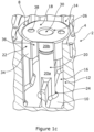
- filter apparatus 2 comprising a filter housing 4 having a plurality of resonant cavities defined therein (only two resonant cavities 6, 8 are shown in the drawings for clarity purposes).
- the filter housing 4 and resonant cavities are formed from electrically conductive material or have an outer electrical conductive coating provided thereon.
- Each resonant cavity 6, 8 is defined between a base 10 and side walls 12 within the filter housing 4.
- An opening 14 is provided at the top of the cavity and is typically covered by a lid (not shown) when the filter apparatus 2 is fully assembled to close the cavity 6, 8 in use.
- An aperture or iris 16 is defined in the side wall 12 between adjacent resonant cavities 6, 8 to provide fluid communication between the resonant cavities 6, 8.
- a resonator 18, 18' is provided in each resonant cavity 6, 8.
- Each resonator 18, 18' includes a first resonator portion in the form of a hollow upright post 20 and a second resonator portion 22 in the form of an outwardly extending skirt.
- the post 20 has a first end 24 located on base 10 and a second end 26 opposite and a spaced distance apart from first end 24.
- the second end 26 is arranged to be adjacent to but a spaced distance apart from a lid that is fitted over the resonant cavity in use.
- the post 20 is shown to comprise two parts 20a and 20b, which are joined together via a fixing screw 28.
- the part 20a is integrally formed with the resonant cavity.
- the post 20 could be a single integral member or could include more than 2 parts joined together.
- the post 20 could also be joined directly to the base 10 of the resonant cavity via any suitable means, such as via solder, welding, adhesive, one or more screws, inter-engaging members, push fit connection and/or the like.
- At least part 20b of post 20 is hollow to allow the fixing screw 28 to be inserted therethrough via an opening 30 provided at the second end 26 of post 20.
- the post 20 could be hollow along its entire length or the post could be solid.
- the opening 30 in the second end 26 of the resonator may also not be provided in some embodiments.
- the second resonator portion 22 is integrally formed with the first resonator portion at the second end 26 of the first resonator portion.
- the second resonator portion 22 includes a first section 32 and a second section 34.
- the first section 32 extends transversally from the second end 26 of the post 20 to create a top surface of the resonator 18, 18'.
- the first section 32 is perpendicular to the post 20.
- the second section 34 protrudes outwardly from and extends transversally to the first section 32.
- the second section 34 points towards the first end 24 of the post 20.
- the second section 34 is perpendicular to the first section 32 and is parallel to the post 20.
- the second section 34 provides a skirt to the second resonator portion 20.
- the combination of the first resonator portion 20 and the second resonator portion 22 provides a mushroom shaped resonator.
- the top of the resonator folds back on itself to create an inverted U-shaped channel, the opening of which faces towards the base of the resonant cavity. It is known to provide mushroom shaped resonators.
- an aperture 36 is defined in the second part 34 or skirt of the resonator 18, 18'. The aperture 36 in the resonator is aligned with the iris 16 defined between two adjacent resonant cavities 18, 18'.
- This provides a line of sight between the first upright posts 20 of the adjacent resonators 18, 18', thereby allowing an area between the adjacent resonators unhindered by the presence of any walls or shields to the electromagnetic fields created by the resonators to allow the electromagnetic fields of the two adjacent resonators to interact with each other.
- This increases the electromagnetic coupling between the adjacent resonators 18, 18' and allows an increased bandwidth to be provided by the resulting filter apparatus in which the resonators are located.
- Each of the resonators 18, 18' can be provided with two apertures 36 on opposite sides of the resonators to allow electromagnetic coupling of each resonators with adjacent resonators on both sides of the same. It will be appreciated that the apertures 36 do not have to be directly opposite to each other and the position of the apertures 36 typically depend on the location of the iris 16 of the adjacent resonant cavity.
- the first part 32 of the resonators 18, 18' are shown with apertures 38 defined therein. These apertures 38 are to help with positioning and/or connecting the resonator in the resonant cavity in use.
- the apertures 38 are not essential to the invention and the first part 32 of the resonator 18, 18' could be provided as a continuous surface without any apertures defined therein.
- the apertures 38 are preferably distinct and separate to the apertures 36 of the second resonator portion.
- first part 32 of the resonators 18, 18' appears to be circular in top plan view with minor segments of the circle cut off by a chord in the area immediately adjacent the apertures 36. This is typically arranged in this manner so as to fit the design of the filter housing.
- first part 32 of the resonator in top plan view can be any shape, such as square, hexagonal, circular and/or the like.
- the coupling bandwidth that is possible using the present invention is 23Mhz compared to a coupling bandwidth of 10.7Mhz when using a mushroom resonator without a cut-out provided in the outer flange wall.
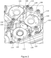
- FIG 2 there is illustrated part of filter apparatus 102 according to a further embodiment of the present invention.
- a first resonator 104 is provided in a first resonant cavity 106
- a second resonator 108 is provided in a second resonant cavity 110
- a third resonator 112 is provided in a third resonant cavity 114.
- the second resonator portion 116 of the first resonator 104 has a single aperture 118 in the outer side wall of the same.
- the second resonator portion 120 of the second resonator 108 has an enlarged aperture 122 that extends over two outer side walls of the same and is L shaped.
- the second resonator portion 124 of the third resonator 112 has a single aperture 126 in the outer side walls of the same.
- Iris 130 is provided between the first and second resonant cavities 106, 110 and iris 132 is provided between the second and third resonant cavities 110, 114.
- the L-shaped extended aperture 122 is in the line of sight or is aligned with both the aperture 118 of the first resonator 104 and the aperture 126 of the third aperture.
- every resonator it is not essential for the present invention for every resonator to have two separate apertures in the second resonator portion or for the apertures in the second resonator portion to be provided opposite to each other.
Landscapes
- Physics & Mathematics (AREA)
- Electromagnetism (AREA)
- Control Of Motors That Do Not Use Commutators (AREA)
Claims (12)
- Filtervorrichtung (2, 102), wobei die genannte Filtervorrichtung (2, 102) ein Gehäuse (4) mit zwei oder mehr darin definierten Resonanzräumen (6, 8, 106, 110) und eine zwischen zwei benachbarten der zwei oder mehr Resonanzräume (6, 8, 106, 110) bereitgestellte Wand (12), die eine in ihr definierte Iris (16) aufweist, beinhaltet, wobei jeder der genannten zwei oder mehr Resonanzräume (6, 8, 106, 110) darin bereitgestellte Resonatormittel (18, 18', 104, 108, 112) aufweist, wobei jedes der genannten Resonatormittel (18, 18', 104, 108, 112) einen ersten Resonatorteil (20) und einen zweiten Resonatorteil (22, 116, 120, 124) aufweist, wobei ein erstes Ende (24) des ersten Resonatorteils (20) an einer Wand (10) des Resonanzraums (6, 8, 106, 110) positioniert ist, wobei der zweite Resonatorteil (22, 116, 120, 124) an einem zweiten Ende (26) des ersten Resonatorteils (20) bereitgestellt ist, wobei der zweite Resonatorteil (22, 116, 120, 124) eine Außenwand beinhaltet, die in einem gewissen Abstand von dem ersten Resonatorteil (20) angeordnet ist, und wobei zwischen dem ersten Resonatorteil (20) und der Außenwand des zweiten Resonatorteils (22, 116, 120, 124) ein Kanal definiert ist, wobei eine Öffnung des Kanals so angeordnet ist, dass sie der Wand (10) des Resonanzraums (6, 8, 106, 110) gegenüberliegt, an der das erste Ende (24) des ersten Resonatorteils (20) positioniert ist, wobei:a) die Außenwand des zweiten Resonatorteils (22, 116, 120, 124) einen Querschnittsumfang des ersten Resonatorteils (20) mit Ausnahme von ein oder mehr darin definierten Aperturen (36, 118, 122, 126), Schlitzen oder Aussparungen vollständig umgibt; oderb) die Außenwand des zweiten Resonatorteils (22, 116, 120, 124) einen Querschnittsumfang des ersten Resonatorteils (20) vollständig umgibt und ein oder mehr Aperturen (36, 118, 122, 126), Schlitze oder Aussparungen in der Außenwand des zweiten Resonatorteils (22, 116, 120, 124) positioniert sind und zu einem Umfangsrand des zweiten Resonatorteils (22, 116, 120, 124) nicht offen sind,und wobei in entweder a) oder b) mindestens eine(r) der Aperturen (36, 118, 122, 126), Schlitze oder Aussparungen auf die Iris (16), die zu dem benachbarten Resonanzraum (6, 8, 106, 110) führt, ausgerichtet oder zumindest teilweise ausgerichtet ist und die Aperturen (36, 118, 122, 126), Schlitze oder Aussparungen und die Resonanzräume (6, 8, 106, 110) angeordnet sind, um eine Sichtverbindung zwischen den ersten Resonatorteilen (20) des Resonatormittels (18, 18', 104, 108, 112) der zwei benachbarten Resonanzräume (6, 8, 106, 110) bereitzustellen.
- Filtervorrichtung nach Anspruch 1, wobei die zwei oder mehr Aperturen (36, 118, 122, 126), Schlitze oder Aussparungen an der bzw. den Außenwand oder -wänden des zweiten Resonatorteils (22, 116, 120, 124) definiert sind und die genannten zwei oder mehr Aperturen (36, 118, 122, 126), Schlitze oder Aussparungen in einem gewissen Abstand voneinander bereitgestellt sind und/oder angeordnet sind, um einander am zweiten Resonatorteil (22, 116, 120, 124) entgegengesetzt zu sein.
- Filtervorrichtung nach Anspruch 1, wobei die Apertur (36, 118, 122, 126), der Schlitz oder die Aussparung an oder sich über zwei oder mehr Außenwände des Resonatorteils (22, 116, 120, 124) definiert ist oder erstreckt.
- Filtervorrichtung nach Anspruch 1, wobei die Wand (10) des Resonanzraums (6, 8, 106, 110), an der sich der erste Resonatorteil (20) des Resonatormittels (18, 18', 104, 108, 112) befindet, ein Boden oder eine elektrische Massefläche des Resonanzraums (6, 8, 106, 110) ist.
- Filtervorrichtung nach Anspruch 1, wobei der erste Resonatorteil (20) des Resonatormittels (18, 18', 104, 108, 112) die Form eines aufrechten Ständers, eines vertikalen Ständers, einer Stange oder eines Körpers hat.
- Filtervorrichtung nach Anspruch 1, wobei der erste Resonatorteil (20) des Resonatormittels (18, 18', 104, 108, 112) aus einem einzelnen einstückigen Element besteht oder zwei oder mehr aneinandergefügte Elemente (20a, 20b) umfasst.
- Filtervorrichtung nach Anspruch 1, wobei das Resonatormittel (18, 18', 104, 108, 112), der erste Resonatorteil (20) und/oder der zweite Resonatorteil (22, 116, 120, 124) hohl sind, im Wesentlichen hohl sind oder einen darin definierten hohlen Abschnitt aufweisen.
- Filtervorrichtung nach Anspruch 1, wobei die Außenwand des zweiten Resonatorteils (22, 116, 120, 124), in der die Apertur (36, 118, 122, 126), die Aussparung oder der Schlitz definiert ist, zu dem ersten Resonatorteil (20) parallel oder im Wesentlichen parallel ist.
- Filtervorrichtung nach Anspruch 1, wobei der zweite Resonatorteil (22, 116, 120, 124) einen ersten Wandabschnitt (32) und einen zweiten Wandabschnitt (34) beinhaltet, der erste Wandabschnitt (32) ein oberes Ende des Resonatormittels (18, 18', 104, 108, 112) bildet und der zweite Wandabschnitt (34) die Außenwand des Resonatormittels (18, 18', 104, 108, 112) bildet.
- Filtervorrichtung nach Anspruch 1, wobei die ein oder mehr Abstimmschrauben oder Abstimmmittel an dem bzw. dem Resonatormittel (18, 18', 104, 108, 112) und/oder an einem bzw. einem Deckel oder einer Abdeckung des Resonanzraums (6, 8, 106, 110) zum Abstimmen der Resonanzfrequenz des Resonatormittels (18, 18', 104, 108, 112) im Gebrauch bereitgestellt oder zugeordnet sind.
- Filtervorrichtung nach Anspruch 10, wobei mindestens ein Teil der Abstimmschraube oder des Abstimmmittels angeordnet ist, um sich im Gebrauch hin zu bzw. weg von dem zweiten Ende (26) des ersten Resonatorteils (20) zu bewegen, angeordnet ist, um sich zumindest teilweise in einem hohlen Teil des ersten Resonatorteils (20) oder dem zweiten Ende (26) des ersten Resonatorteils (20) zu befinden, und/oder angeordnet ist, um sich in und/oder relativ zu einem im ersten Resonatorteil (20) definierten Kanal oder hohlen Teil zu bewegen.
- Verfahren zur Verwendung einer Filtervorrichtung (2, 102), wobei die genannte Filtervorrichtung (2, 102) ein Gehäuse (4) mit zwei oder mehr darin definierten Resonanzräumen (6, 8, 106, 110) und eine zwischen zwei benachbarten der zwei oder mehr Resonanzräume (6, 8, 106, 110) bereitgestellte Wand (12), die eine in ihr definierte Iris (16) aufweist, beinhaltet, wobei das genannte Verfahren die folgenden Schritte beinhaltet: Versehen von jedem der genannten zwei oder mehr Resonanzräume (6, 8, 106, 110) mit Resonatormitteln (18, 18', 104, 108, 112) in ihnen, wobei jedes der genannten Resonatormittel (18, 18', 104, 108, 112) einen ersten Resonatorteil (20) und einen zweiten Resonatorteil (22, 116, 120, 124) aufweist, Positionieren eines ersten Endes (24) des ersten Resonatorteils (20) an einer Wand des Resonanzraums (6, 8, 106, 110), Bereitstellen des zweiten Resonatorteils (22, 116, 120, 124) an einem zweiten Ende (26) des ersten Resonatorteils (20), wobei der zweite Resonatorteil (22, 116, 120, 124) eine Außenwand beinhaltet, die in einem gewissen Abstand von dem ersten Resonatorteil (20) angeordnet ist, und zwischen dem ersten Resonatorteil (20) und der Außenwand des zweiten Resonatorteils (22, 116, 120, 124) ein Kanal definiert ist, Anordnen des zweiten Resonatorteils (22, 116, 120, 124), so dass eine Öffnung des Kanals der Wand (10) des Resonanzraums (6, 8, 106, 110) gegenüberliegt, an der das erste Ende (24) des ersten Resonatorteils (20) positioniert wurde, wobei:a) die Außenwand des zweiten Resonatorteils (22, 116, 120, 124) einen Querschnittsumfang des ersten Resonatorteils (20) mit Ausnahme von ein oder mehr darin definierten Aperturen (36, 118, 122, 126), Schlitzen oder Aussparungen vollständig umgibt; oderb) die Außenwand des zweiten Resonatorteils (22, 116, 120, 124) einen Querschnittsumfang des ersten Resonatorteils (20) vollständig umgibt und ein oder mehr Aperturen (36, 118, 122, 126), Schlitze oder Aussparungen in der Außenwand des zweiten Resonatorteils (22, 116, 120, 124) positioniert sind und zu einem Umfangsrand des zweiten Resonatorteils (22, 116, 120, 124) nicht offen sind,und wobei in entweder a) oder b) mindestens eine(r) der Aperturen (36, 118, 122, 126), Schlitze oder Aussparungen auf die Iris (16), die zu dem benachbarten Resonanzraum (6, 8, 106, 110) führt, ausgerichtet oder zumindest teilweise ausgerichtet ist und die Aperturen (36, 118, 122, 126), Schlitze oder Aussparungen und die Resonanzräume (6, 8, 106, 110) angeordnet sind, um eine Sichtverbindung zwischen den ersten Resonatorteilen (20) des Resonatormittels (18, 18', 104, 108, 112) der zwei benachbarten Resonanzräume (6, 8, 106, 110) bereitzustellen.
Applications Claiming Priority (1)
| Application Number | Priority Date | Filing Date | Title |
|---|---|---|---|
| GBGB1904808.1A GB201904808D0 (en) | 2019-04-05 | 2019-04-05 | Filter apparatus and method of use thereof |
Publications (3)
| Publication Number | Publication Date |
|---|---|
| EP3731337A1 EP3731337A1 (de) | 2020-10-28 |
| EP3731337C0 EP3731337C0 (de) | 2024-01-24 |
| EP3731337B1 true EP3731337B1 (de) | 2024-01-24 |
Family
ID=66809581
Family Applications (1)
| Application Number | Title | Priority Date | Filing Date |
|---|---|---|---|
| EP20275072.5A Active EP3731337B1 (de) | 2019-04-05 | 2020-04-02 | Filtervorrichtung und verfahren zur verwendung davon |
Country Status (2)
| Country | Link |
|---|---|
| EP (1) | EP3731337B1 (de) |
| GB (1) | GB201904808D0 (de) |
Cited By (1)
| Publication number | Priority date | Publication date | Assignee | Title |
|---|---|---|---|---|
| WO2026027773A1 (en) * | 2024-08-01 | 2026-02-05 | Commscope Italy S.R.L. | Radio frequency filters realized by a cascade of hybridly coupled resonators |
Families Citing this family (1)
| Publication number | Priority date | Publication date | Assignee | Title |
|---|---|---|---|---|
| CN119812708B (zh) * | 2025-02-06 | 2025-10-21 | 南通大学 | 面向卫星通信的小型化宽阻带腔体带通滤波器及制作方法 |
Citations (1)
| Publication number | Priority date | Publication date | Assignee | Title |
|---|---|---|---|---|
| US20020036551A1 (en) * | 2000-09-22 | 2002-03-28 | Filtronic Lk Oy | Resonator filter |
Family Cites Families (4)
| Publication number | Priority date | Publication date | Assignee | Title |
|---|---|---|---|---|
| WO1999030383A2 (en) * | 1997-12-11 | 1999-06-17 | Lk-Products Oy | Resonator structure |
| EP2556559A4 (de) | 2010-04-06 | 2014-07-09 | Powerwave Technologies Inc | Hohlraumfilter von reduzierter grösse für pico-basisstationen |
| JP5913975B2 (ja) * | 2011-12-28 | 2016-05-11 | 株式会社日立国際八木ソリューションズ | 半同軸型帯域通過フィルタ |
| KR101730084B1 (ko) * | 2015-04-20 | 2017-04-25 | 주식회사 케이엠더블유 | 캐비티 구조를 가진 무선 주파수 필터 |
-
2019
- 2019-04-05 GB GBGB1904808.1A patent/GB201904808D0/en not_active Ceased
-
2020
- 2020-04-02 EP EP20275072.5A patent/EP3731337B1/de active Active
Patent Citations (1)
| Publication number | Priority date | Publication date | Assignee | Title |
|---|---|---|---|---|
| US20020036551A1 (en) * | 2000-09-22 | 2002-03-28 | Filtronic Lk Oy | Resonator filter |
Cited By (1)
| Publication number | Priority date | Publication date | Assignee | Title |
|---|---|---|---|---|
| WO2026027773A1 (en) * | 2024-08-01 | 2026-02-05 | Commscope Italy S.R.L. | Radio frequency filters realized by a cascade of hybridly coupled resonators |
Also Published As
| Publication number | Publication date |
|---|---|
| GB201904808D0 (en) | 2019-05-22 |
| EP3731337C0 (de) | 2024-01-24 |
| EP3731337A1 (de) | 2020-10-28 |
Similar Documents
| Publication | Publication Date | Title |
|---|---|---|
| KR101869757B1 (ko) | 캐비티 구조를 가진 무선 주파수 필터 | |
| US6037541A (en) | Apparatus and method for forming a housing assembly | |
| FI98417C (fi) | Siirtojohtoresonaattorisuodatin | |
| KR101677950B1 (ko) | 크로스 커플링을 이용하는 캐비티 필터 | |
| EP3731337B1 (de) | Filtervorrichtung und verfahren zur verwendung davon | |
| US20020041221A1 (en) | Tunable bandpass filter | |
| CN109768357B (zh) | 一种传输零点可控的基片集成波导滤波器 | |
| US10056664B2 (en) | Three dimensional tunable filters with an absolute constant bandwidth and method | |
| KR101939989B1 (ko) | 고주파 필터 | |
| FI127061B (en) | Control element for radio frequency resonator | |
| KR102196518B1 (ko) | 유전체 공진기 안테나와 이를 구비하는 mimo 안테나 및 무선 통신 장치 | |
| KR101357027B1 (ko) | 리엔트런트 캐비티형 유전체 공진기를 이용한 듀얼 모드 유전체 공진기 필터 | |
| KR101157689B1 (ko) | 고주파 필터 | |
| US9595746B2 (en) | Semi-coaxial resonator comprised of columnar shaped resonant elements with square shaped plates, where vertical screw holes are disposed in the square shaped plates | |
| EP1746681A1 (de) | Kunststoffkammfilter mit einem Metallpfosten zur Verbesserung der Wärmeabfuhr | |
| GB2499724B (en) | Filter apparatus and method of manufacture thereof | |
| KR102211323B1 (ko) | 고주파 캐비티 필터 및 이를 포함하는 통신 기기 | |
| EP1315228A1 (de) | Dielektrisches filter | |
| EP1791212A1 (de) | Mikrowellenfilter mit einem Kapazitivkopplungselement | |
| EP3014698B1 (de) | Resonatorstruktur für eine hohlraum-filter-anordnung | |
| US7068128B1 (en) | Compact combline resonator and filter | |
| RU2709030C1 (ru) | Полосно-заграждающий фильтр | |
| KR102745333B1 (ko) | 이동통신 서비스 품질 개선용 대역저지필터 | |
| Li et al. | Integration of slot antenna with evanescent-mode filter for tunable front-end applications | |
| KR20100008939A (ko) | 감쇄 특성을 향상시킨 일체형 유전체 필터 및 이를 이용한통신 중계 장치 |
Legal Events
| Date | Code | Title | Description |
|---|---|---|---|
| PUAI | Public reference made under article 153(3) epc to a published international application that has entered the european phase |
Free format text: ORIGINAL CODE: 0009012 |
|
| STAA | Information on the status of an ep patent application or granted ep patent |
Free format text: STATUS: THE APPLICATION HAS BEEN PUBLISHED |
|
| AK | Designated contracting states |
Kind code of ref document: A1 Designated state(s): AL AT BE BG CH CY CZ DE DK EE ES FI FR GB GR HR HU IE IS IT LI LT LU LV MC MK MT NL NO PL PT RO RS SE SI SK SM TR |
|
| AX | Request for extension of the european patent |
Extension state: BA ME |
|
| STAA | Information on the status of an ep patent application or granted ep patent |
Free format text: STATUS: REQUEST FOR EXAMINATION WAS MADE |
|
| 17P | Request for examination filed |
Effective date: 20210422 |
|
| RBV | Designated contracting states (corrected) |
Designated state(s): AL AT BE BG CH CY CZ DE DK EE ES FI FR GB GR HR HU IE IS IT LI LT LU LV MC MK MT NL NO PL PT RO RS SE SI SK SM TR |
|
| STAA | Information on the status of an ep patent application or granted ep patent |
Free format text: STATUS: EXAMINATION IS IN PROGRESS |
|
| 17Q | First examination report despatched |
Effective date: 20220509 |
|
| GRAP | Despatch of communication of intention to grant a patent |
Free format text: ORIGINAL CODE: EPIDOSNIGR1 |
|
| STAA | Information on the status of an ep patent application or granted ep patent |
Free format text: STATUS: GRANT OF PATENT IS INTENDED |
|
| INTG | Intention to grant announced |
Effective date: 20231016 |
|
| GRAS | Grant fee paid |
Free format text: ORIGINAL CODE: EPIDOSNIGR3 |
|
| GRAA | (expected) grant |
Free format text: ORIGINAL CODE: 0009210 |
|
| STAA | Information on the status of an ep patent application or granted ep patent |
Free format text: STATUS: THE PATENT HAS BEEN GRANTED |
|
| AK | Designated contracting states |
Kind code of ref document: B1 Designated state(s): AL AT BE BG CH CY CZ DE DK EE ES FI FR GB GR HR HU IE IS IT LI LT LU LV MC MK MT NL NO PL PT RO RS SE SI SK SM TR |
|
| REG | Reference to a national code |
Ref country code: GB Ref legal event code: FG4D |
|
| REG | Reference to a national code |
Ref country code: CH Ref legal event code: EP |
|
| REG | Reference to a national code |
Ref country code: DE Ref legal event code: R096 Ref document number: 602020024799 Country of ref document: DE |
|
| REG | Reference to a national code |
Ref country code: IE Ref legal event code: FG4D |
|
| U01 | Request for unitary effect filed |
Effective date: 20240124 |
|
| U07 | Unitary effect registered |
Designated state(s): AT BE BG DE DK EE FI FR IT LT LU LV MT NL PT SE SI Effective date: 20240201 |
|
| U20 | Renewal fee for the european patent with unitary effect paid |
Year of fee payment: 5 Effective date: 20240410 |
|
| PG25 | Lapsed in a contracting state [announced via postgrant information from national office to epo] |
Ref country code: IS Free format text: LAPSE BECAUSE OF FAILURE TO SUBMIT A TRANSLATION OF THE DESCRIPTION OR TO PAY THE FEE WITHIN THE PRESCRIBED TIME-LIMIT Effective date: 20240524 |
|
| PG25 | Lapsed in a contracting state [announced via postgrant information from national office to epo] |
Ref country code: GR Free format text: LAPSE BECAUSE OF FAILURE TO SUBMIT A TRANSLATION OF THE DESCRIPTION OR TO PAY THE FEE WITHIN THE PRESCRIBED TIME-LIMIT Effective date: 20240425 |
|
| PG25 | Lapsed in a contracting state [announced via postgrant information from national office to epo] |
Ref country code: HR Free format text: LAPSE BECAUSE OF FAILURE TO SUBMIT A TRANSLATION OF THE DESCRIPTION OR TO PAY THE FEE WITHIN THE PRESCRIBED TIME-LIMIT Effective date: 20240124 Ref country code: RS Free format text: LAPSE BECAUSE OF FAILURE TO SUBMIT A TRANSLATION OF THE DESCRIPTION OR TO PAY THE FEE WITHIN THE PRESCRIBED TIME-LIMIT Effective date: 20240424 |
|
| PG25 | Lapsed in a contracting state [announced via postgrant information from national office to epo] |
Ref country code: ES Free format text: LAPSE BECAUSE OF FAILURE TO SUBMIT A TRANSLATION OF THE DESCRIPTION OR TO PAY THE FEE WITHIN THE PRESCRIBED TIME-LIMIT Effective date: 20240124 |
|
| PG25 | Lapsed in a contracting state [announced via postgrant information from national office to epo] |
Ref country code: RS Free format text: LAPSE BECAUSE OF FAILURE TO SUBMIT A TRANSLATION OF THE DESCRIPTION OR TO PAY THE FEE WITHIN THE PRESCRIBED TIME-LIMIT Effective date: 20240424 Ref country code: NO Free format text: LAPSE BECAUSE OF FAILURE TO SUBMIT A TRANSLATION OF THE DESCRIPTION OR TO PAY THE FEE WITHIN THE PRESCRIBED TIME-LIMIT Effective date: 20240424 Ref country code: IS Free format text: LAPSE BECAUSE OF FAILURE TO SUBMIT A TRANSLATION OF THE DESCRIPTION OR TO PAY THE FEE WITHIN THE PRESCRIBED TIME-LIMIT Effective date: 20240524 Ref country code: HR Free format text: LAPSE BECAUSE OF FAILURE TO SUBMIT A TRANSLATION OF THE DESCRIPTION OR TO PAY THE FEE WITHIN THE PRESCRIBED TIME-LIMIT Effective date: 20240124 Ref country code: GR Free format text: LAPSE BECAUSE OF FAILURE TO SUBMIT A TRANSLATION OF THE DESCRIPTION OR TO PAY THE FEE WITHIN THE PRESCRIBED TIME-LIMIT Effective date: 20240425 Ref country code: ES Free format text: LAPSE BECAUSE OF FAILURE TO SUBMIT A TRANSLATION OF THE DESCRIPTION OR TO PAY THE FEE WITHIN THE PRESCRIBED TIME-LIMIT Effective date: 20240124 |
|
| PG25 | Lapsed in a contracting state [announced via postgrant information from national office to epo] |
Ref country code: PL Free format text: LAPSE BECAUSE OF FAILURE TO SUBMIT A TRANSLATION OF THE DESCRIPTION OR TO PAY THE FEE WITHIN THE PRESCRIBED TIME-LIMIT Effective date: 20240124 |
|
| PG25 | Lapsed in a contracting state [announced via postgrant information from national office to epo] |
Ref country code: PL Free format text: LAPSE BECAUSE OF FAILURE TO SUBMIT A TRANSLATION OF THE DESCRIPTION OR TO PAY THE FEE WITHIN THE PRESCRIBED TIME-LIMIT Effective date: 20240124 |
|
| PG25 | Lapsed in a contracting state [announced via postgrant information from national office to epo] |
Ref country code: SM Free format text: LAPSE BECAUSE OF FAILURE TO SUBMIT A TRANSLATION OF THE DESCRIPTION OR TO PAY THE FEE WITHIN THE PRESCRIBED TIME-LIMIT Effective date: 20240124 |
|
| PG25 | Lapsed in a contracting state [announced via postgrant information from national office to epo] |
Ref country code: CZ Free format text: LAPSE BECAUSE OF FAILURE TO SUBMIT A TRANSLATION OF THE DESCRIPTION OR TO PAY THE FEE WITHIN THE PRESCRIBED TIME-LIMIT Effective date: 20240124 |
|
| REG | Reference to a national code |
Ref country code: DE Ref legal event code: R097 Ref document number: 602020024799 Country of ref document: DE |
|
| PG25 | Lapsed in a contracting state [announced via postgrant information from national office to epo] |
Ref country code: SK Free format text: LAPSE BECAUSE OF FAILURE TO SUBMIT A TRANSLATION OF THE DESCRIPTION OR TO PAY THE FEE WITHIN THE PRESCRIBED TIME-LIMIT Effective date: 20240124 |
|
| PG25 | Lapsed in a contracting state [announced via postgrant information from national office to epo] |
Ref country code: SM Free format text: LAPSE BECAUSE OF FAILURE TO SUBMIT A TRANSLATION OF THE DESCRIPTION OR TO PAY THE FEE WITHIN THE PRESCRIBED TIME-LIMIT Effective date: 20240124 Ref country code: SK Free format text: LAPSE BECAUSE OF FAILURE TO SUBMIT A TRANSLATION OF THE DESCRIPTION OR TO PAY THE FEE WITHIN THE PRESCRIBED TIME-LIMIT Effective date: 20240124 Ref country code: CZ Free format text: LAPSE BECAUSE OF FAILURE TO SUBMIT A TRANSLATION OF THE DESCRIPTION OR TO PAY THE FEE WITHIN THE PRESCRIBED TIME-LIMIT Effective date: 20240124 |
|
| PG25 | Lapsed in a contracting state [announced via postgrant information from national office to epo] |
Ref country code: MC Free format text: LAPSE BECAUSE OF FAILURE TO SUBMIT A TRANSLATION OF THE DESCRIPTION OR TO PAY THE FEE WITHIN THE PRESCRIBED TIME-LIMIT Effective date: 20240124 |
|
| PG25 | Lapsed in a contracting state [announced via postgrant information from national office to epo] |
Ref country code: MC Free format text: LAPSE BECAUSE OF FAILURE TO SUBMIT A TRANSLATION OF THE DESCRIPTION OR TO PAY THE FEE WITHIN THE PRESCRIBED TIME-LIMIT Effective date: 20240124 |
|
| PLBE | No opposition filed within time limit |
Free format text: ORIGINAL CODE: 0009261 |
|
| REG | Reference to a national code |
Ref country code: CH Ref legal event code: PL |
|
| STAA | Information on the status of an ep patent application or granted ep patent |
Free format text: STATUS: NO OPPOSITION FILED WITHIN TIME LIMIT |
|
| 26N | No opposition filed |
Effective date: 20241025 |
|
| PG25 | Lapsed in a contracting state [announced via postgrant information from national office to epo] |
Ref country code: CH Free format text: LAPSE BECAUSE OF NON-PAYMENT OF DUE FEES Effective date: 20240430 |
|
| PG25 | Lapsed in a contracting state [announced via postgrant information from national office to epo] |
Ref country code: IE Free format text: LAPSE BECAUSE OF NON-PAYMENT OF DUE FEES Effective date: 20240402 |
|
| U20 | Renewal fee for the european patent with unitary effect paid |
Year of fee payment: 6 Effective date: 20250411 |
|
| PGFP | Annual fee paid to national office [announced via postgrant information from national office to epo] |
Ref country code: GB Payment date: 20250411 Year of fee payment: 6 |
|
| PG25 | Lapsed in a contracting state [announced via postgrant information from national office to epo] |
Ref country code: RO Free format text: LAPSE BECAUSE OF FAILURE TO SUBMIT A TRANSLATION OF THE DESCRIPTION OR TO PAY THE FEE WITHIN THE PRESCRIBED TIME-LIMIT Effective date: 20240124 |
|
| U1H | Name or address of the proprietor changed after the registration of the unitary effect |
Owner name: RADIO DESIGN LIMITED; GB |
|
| PG25 | Lapsed in a contracting state [announced via postgrant information from national office to epo] |
Ref country code: CY Free format text: LAPSE BECAUSE OF FAILURE TO SUBMIT A TRANSLATION OF THE DESCRIPTION OR TO PAY THE FEE WITHIN THE PRESCRIBED TIME-LIMIT; INVALID AB INITIO Effective date: 20200402 |
|
| PG25 | Lapsed in a contracting state [announced via postgrant information from national office to epo] |
Ref country code: HU Free format text: LAPSE BECAUSE OF FAILURE TO SUBMIT A TRANSLATION OF THE DESCRIPTION OR TO PAY THE FEE WITHIN THE PRESCRIBED TIME-LIMIT; INVALID AB INITIO Effective date: 20200402 |
|
| PG25 | Lapsed in a contracting state [announced via postgrant information from national office to epo] |
Ref country code: TR Free format text: LAPSE BECAUSE OF FAILURE TO SUBMIT A TRANSLATION OF THE DESCRIPTION OR TO PAY THE FEE WITHIN THE PRESCRIBED TIME-LIMIT Effective date: 20240124 |