EP3731297B1 - Battery module - Google Patents
Battery module Download PDFInfo
- Publication number
- EP3731297B1 EP3731297B1 EP19220159.8A EP19220159A EP3731297B1 EP 3731297 B1 EP3731297 B1 EP 3731297B1 EP 19220159 A EP19220159 A EP 19220159A EP 3731297 B1 EP3731297 B1 EP 3731297B1
- Authority
- EP
- European Patent Office
- Prior art keywords
- terminal
- peripheral surface
- plate
- electrode terminal
- region
- Prior art date
- Legal status (The legal status is an assumption and is not a legal conclusion. Google has not performed a legal analysis and makes no representation as to the accuracy of the status listed.)
- Active
Links
Images


Classifications
-
- H—ELECTRICITY
- H01—ELECTRIC ELEMENTS
- H01M—PROCESSES OR MEANS, e.g. BATTERIES, FOR THE DIRECT CONVERSION OF CHEMICAL ENERGY INTO ELECTRICAL ENERGY
- H01M50/00—Constructional details or processes of manufacture of the non-active parts of electrochemical cells other than fuel cells, e.g. hybrid cells
- H01M50/10—Primary casings; Jackets or wrappings
- H01M50/147—Lids or covers
- H01M50/148—Lids or covers characterised by their shape
- H01M50/15—Lids or covers characterised by their shape for prismatic or rectangular cells
-
- H—ELECTRICITY
- H01—ELECTRIC ELEMENTS
- H01M—PROCESSES OR MEANS, e.g. BATTERIES, FOR THE DIRECT CONVERSION OF CHEMICAL ENERGY INTO ELECTRICAL ENERGY
- H01M50/00—Constructional details or processes of manufacture of the non-active parts of electrochemical cells other than fuel cells, e.g. hybrid cells
- H01M50/10—Primary casings; Jackets or wrappings
- H01M50/102—Primary casings; Jackets or wrappings characterised by their shape or physical structure
- H01M50/103—Primary casings; Jackets or wrappings characterised by their shape or physical structure prismatic or rectangular
-
- H—ELECTRICITY
- H01—ELECTRIC ELEMENTS
- H01M—PROCESSES OR MEANS, e.g. BATTERIES, FOR THE DIRECT CONVERSION OF CHEMICAL ENERGY INTO ELECTRICAL ENERGY
- H01M50/00—Constructional details or processes of manufacture of the non-active parts of electrochemical cells other than fuel cells, e.g. hybrid cells
- H01M50/10—Primary casings; Jackets or wrappings
- H01M50/147—Lids or covers
-
- H—ELECTRICITY
- H01—ELECTRIC ELEMENTS
- H01M—PROCESSES OR MEANS, e.g. BATTERIES, FOR THE DIRECT CONVERSION OF CHEMICAL ENERGY INTO ELECTRICAL ENERGY
- H01M50/00—Constructional details or processes of manufacture of the non-active parts of electrochemical cells other than fuel cells, e.g. hybrid cells
- H01M50/10—Primary casings; Jackets or wrappings
- H01M50/172—Arrangements of electric connectors penetrating the casing
- H01M50/174—Arrangements of electric connectors penetrating the casing adapted for the shape of the cells
- H01M50/176—Arrangements of electric connectors penetrating the casing adapted for the shape of the cells for prismatic or rectangular cells
-
- H—ELECTRICITY
- H01—ELECTRIC ELEMENTS
- H01M—PROCESSES OR MEANS, e.g. BATTERIES, FOR THE DIRECT CONVERSION OF CHEMICAL ENERGY INTO ELECTRICAL ENERGY
- H01M50/00—Constructional details or processes of manufacture of the non-active parts of electrochemical cells other than fuel cells, e.g. hybrid cells
- H01M50/10—Primary casings; Jackets or wrappings
- H01M50/183—Sealing members
- H01M50/186—Sealing members characterised by the disposition of the sealing members
- H01M50/188—Sealing members characterised by the disposition of the sealing members the sealing members being arranged between the lid and terminal
-
- H—ELECTRICITY
- H01—ELECTRIC ELEMENTS
- H01M—PROCESSES OR MEANS, e.g. BATTERIES, FOR THE DIRECT CONVERSION OF CHEMICAL ENERGY INTO ELECTRICAL ENERGY
- H01M50/00—Constructional details or processes of manufacture of the non-active parts of electrochemical cells other than fuel cells, e.g. hybrid cells
- H01M50/50—Current conducting connections for cells or batteries
- H01M50/502—Interconnectors for connecting terminals of adjacent batteries; Interconnectors for connecting cells outside a battery casing
-
- H—ELECTRICITY
- H01—ELECTRIC ELEMENTS
- H01M—PROCESSES OR MEANS, e.g. BATTERIES, FOR THE DIRECT CONVERSION OF CHEMICAL ENERGY INTO ELECTRICAL ENERGY
- H01M50/00—Constructional details or processes of manufacture of the non-active parts of electrochemical cells other than fuel cells, e.g. hybrid cells
- H01M50/50—Current conducting connections for cells or batteries
- H01M50/502—Interconnectors for connecting terminals of adjacent batteries; Interconnectors for connecting cells outside a battery casing
- H01M50/514—Methods for interconnecting adjacent batteries or cells
- H01M50/516—Methods for interconnecting adjacent batteries or cells by welding, soldering or brazing
-
- H—ELECTRICITY
- H01—ELECTRIC ELEMENTS
- H01M—PROCESSES OR MEANS, e.g. BATTERIES, FOR THE DIRECT CONVERSION OF CHEMICAL ENERGY INTO ELECTRICAL ENERGY
- H01M50/00—Constructional details or processes of manufacture of the non-active parts of electrochemical cells other than fuel cells, e.g. hybrid cells
- H01M50/50—Current conducting connections for cells or batteries
- H01M50/528—Fixed electrical connections, i.e. not intended for disconnection
-
- H—ELECTRICITY
- H01—ELECTRIC ELEMENTS
- H01M—PROCESSES OR MEANS, e.g. BATTERIES, FOR THE DIRECT CONVERSION OF CHEMICAL ENERGY INTO ELECTRICAL ENERGY
- H01M50/00—Constructional details or processes of manufacture of the non-active parts of electrochemical cells other than fuel cells, e.g. hybrid cells
- H01M50/50—Current conducting connections for cells or batteries
- H01M50/543—Terminals
- H01M50/552—Terminals characterised by their shape
- H01M50/553—Terminals adapted for prismatic, pouch or rectangular cells
-
- H—ELECTRICITY
- H01—ELECTRIC ELEMENTS
- H01M—PROCESSES OR MEANS, e.g. BATTERIES, FOR THE DIRECT CONVERSION OF CHEMICAL ENERGY INTO ELECTRICAL ENERGY
- H01M50/00—Constructional details or processes of manufacture of the non-active parts of electrochemical cells other than fuel cells, e.g. hybrid cells
- H01M50/50—Current conducting connections for cells or batteries
- H01M50/543—Terminals
- H01M50/552—Terminals characterised by their shape
- H01M50/553—Terminals adapted for prismatic, pouch or rectangular cells
- H01M50/557—Plate-shaped terminals
-
- H—ELECTRICITY
- H01—ELECTRIC ELEMENTS
- H01M—PROCESSES OR MEANS, e.g. BATTERIES, FOR THE DIRECT CONVERSION OF CHEMICAL ENERGY INTO ELECTRICAL ENERGY
- H01M50/00—Constructional details or processes of manufacture of the non-active parts of electrochemical cells other than fuel cells, e.g. hybrid cells
- H01M50/50—Current conducting connections for cells or batteries
- H01M50/543—Terminals
- H01M50/547—Terminals characterised by the disposition of the terminals on the cells
- H01M50/55—Terminals characterised by the disposition of the terminals on the cells on the same side of the cell
-
- H—ELECTRICITY
- H01—ELECTRIC ELEMENTS
- H01M—PROCESSES OR MEANS, e.g. BATTERIES, FOR THE DIRECT CONVERSION OF CHEMICAL ENERGY INTO ELECTRICAL ENERGY
- H01M50/00—Constructional details or processes of manufacture of the non-active parts of electrochemical cells other than fuel cells, e.g. hybrid cells
- H01M50/50—Current conducting connections for cells or batteries
- H01M50/543—Terminals
- H01M50/564—Terminals characterised by their manufacturing process
- H01M50/566—Terminals characterised by their manufacturing process by welding, soldering or brazing
-
- Y—GENERAL TAGGING OF NEW TECHNOLOGICAL DEVELOPMENTS; GENERAL TAGGING OF CROSS-SECTIONAL TECHNOLOGIES SPANNING OVER SEVERAL SECTIONS OF THE IPC; TECHNICAL SUBJECTS COVERED BY FORMER USPC CROSS-REFERENCE ART COLLECTIONS [XRACs] AND DIGESTS
- Y02—TECHNOLOGIES OR APPLICATIONS FOR MITIGATION OR ADAPTATION AGAINST CLIMATE CHANGE
- Y02E—REDUCTION OF GREENHOUSE GAS [GHG] EMISSIONS, RELATED TO ENERGY GENERATION, TRANSMISSION OR DISTRIBUTION
- Y02E60/00—Enabling technologies; Technologies with a potential or indirect contribution to GHG emissions mitigation
- Y02E60/10—Energy storage using batteries
-
- Y—GENERAL TAGGING OF NEW TECHNOLOGICAL DEVELOPMENTS; GENERAL TAGGING OF CROSS-SECTIONAL TECHNOLOGIES SPANNING OVER SEVERAL SECTIONS OF THE IPC; TECHNICAL SUBJECTS COVERED BY FORMER USPC CROSS-REFERENCE ART COLLECTIONS [XRACs] AND DIGESTS
- Y02—TECHNOLOGIES OR APPLICATIONS FOR MITIGATION OR ADAPTATION AGAINST CLIMATE CHANGE
- Y02P—CLIMATE CHANGE MITIGATION TECHNOLOGIES IN THE PRODUCTION OR PROCESSING OF GOODS
- Y02P70/00—Climate change mitigation technologies in the production process for final industrial or consumer products
- Y02P70/50—Manufacturing or production processes characterised by the final manufactured product
Definitions
- the present invention relates to the field of battery, and particularly to a battery module, a secondary battery and a cap assembly therefor.
- a secondary battery has the advantages of high energy density, long service life, energy saving, environmental protection and the like, and is widely applied in various fields, such as new energy vehicles and energy storage power stations.
- the busbar is generally welded to an electrode terminal of the secondary battery; however, in the prior art, the positioning accuracy of the electrode terminal and the busbar is worse during welding, resulting in deviation of the welding position of the busbar, insufficient welding strength, and failure of the battery module.
- the features of the preamble of the independent claim are known from CN 208 622 794 U , CN 108 767 1 43 A , EP 3 471 166 A1 .
- Related technologies are known from EP 3 416 213 A2 and JP 2002 124218 A .
- the present invention is to provide a battery module, which may improve the positioning accuracy of the electrode terminal and the busbar, and improve the welding strength.
- the present invention provides a battery module.
- the present invention is set out in the claims.
- a cap assembly for a secondary battery comprises a cap plate and an electrode terminal.
- the cap plate is provided with a terminal hole
- the electrode terminal is provided to the cap plate and covers the terminal hole.
- the electrode terminal comprises an outer surface.
- the electrode terminal comprises a positioning hole, the positioning hole is recessed with respect to the outer surface of the electrode terminal and comprises a first portion and a second portion, the second portion is positioned to a side of the first portion away from the outer surface.
- a section of the first portion parallel to a central axis of the positioning hole is trapezoidal.
- a size of the first portion gradually decreases in a direction of the first portion close to the second portion, and a minimum size of the first portion is greater than or equal to a size of the second portion.
- the first portion has a first peripheral surface, an angle between the first peripheral surface and the outer surface is from 135 degrees to 175 degrees.
- the first portion has a first peripheral surface.
- the outer surface comprises a first region and a second region, the first region surrounds the first peripheral surface and is connected with the first peripheral surface, and the second region surrounds the first region and is connected with the first region.
- a roughness of the first region is greater than a roughness of the first peripheral surface.
- the roughness of the first region is from 1 ⁇ m to 14 ⁇ m.
- a size of the second portion gradually decreases in a direction of the second portion away from the first portion.
- the second portion has a second peripheral surface, the second peripheral surface is a circular arc surface.
- a shape of the second portion is different from a shape of the first portion.
- the positioning hole further comprises a third portion, the third portion is cylindrical and is positioned between the first portion and the second portion.
- the electrode terminal comprises a first terminal plate and a second terminal plate, the first terminal plate is positioned to a side of the second terminal plate away from the cap plate.
- the first terminal plate is made of aluminum and the second terminal plate is made of copper.
- the positioning hole is formed to the first terminal plate, and a depth of the positioning hole is less than a thickness of the first terminal plate.
- the cap assembly further comprises a fixing member, the fixing member connects the cap plate and the electrode terminal, an edge of the electrode terminal is positioned between the fixing member and the cap plate.
- the electrode terminal is provided to a side of the cap plate.
- the cap assembly further comprises a connecting piece, the connecting piece is provided with a bulging portion, the bulging portion extends into the terminal hole and is connected with the electrode terminal.
- the cap assembly further comprises a sealing ring, the sealing ring is provided between the cap plate and the electrode terminal.
- the secondary battery comprises an electrode assembly, a case and the cap assembly described above.
- the electrode assembly is received in the case, the cap plate of the cap assembly is connected to the case, the electrode terminal is provided to a side of the cap plate away from the electrode assembly.
- the battery module comprises the secondary battery described above and a busbar.
- the busbar is connected to the electrode terminal, and the busbar comprises a through hole aligned with the positioning hole of the electrode terminal in a height direction.
- the through hole exposes the first peripheral surface, and a ratio of an exposed area of the first peripheral surface to a total area of the first peripheral surface is greater than 2/3.
- the busbar is welded to the second region of the outer surface, the through hole exposes at least part of the first region.
- the present invention has the following beneficial effects: the present invention makes the CCD device accurately calculate the geometric center of the positioning hole by the configuration of the positioning hole with a specific shape, improve the positioning accuracy between the electrode terminal and the busbar, and avoid the laser acting on the cap plate, thereby improving the welding strength.
- the terms “first”, “second” and “third” are only used for illustrative purposes and are not to be construed as expressing or implying a relative importance.
- the term “plurality” is two or more.
- the term “connect” should be broadly interpreted, for example, the term “connect” can be “fixedly connect”, “detachably connect”, “integrally connect”, “electrically connect” or “signal connect”.
- the term “connect” also can be “directly connect” or “indirectly connect via a medium”.
- a battery module of the present invention may include a plurality of secondary batteries.
- the secondary batteries may be columnar prismatic lithium-ion batteries.
- the plurality of secondary batteries may be arranged sequentially in a width direction Y.
- the battery module may further include an end plate and a side plate.
- the end plate is provided as two in number and the two end plates are respectively provided to both ends of the plurality of secondary batteries in the width direction Y.
- the side plate is provided as two in number and the two side plates are respectively provided to both sides of the plurality of secondary batteries in a length direction X.
- the end plates and the side plates are connected together to form a rectangular frame, the frame fixes the plurality of secondary batteries.
- the secondary battery of the present invention includes a cap assembly 1, an electrode assembly 2 and a case 3.
- the electrode assembly 2 is a core member for achieving charge and discharge function of the secondary battery.
- the electrode assembly 2 includes a positive electrode plate, a negative electrode plate and a separator, the separator separates the positive electrode plate and the negative electrode plate.
- the positive electrode plate includes a positive current collector and a positive active material layer coated on a surface of the positive current collector, the positive current collector may be an aluminum foil, the positive active material layer includes a ternary material, lithium manganese oxide or lithium iron phosphate.
- the negative electrode plate includes a negative current collector and a negative active material layer coated on a surface of the negative current collector, the negative current collector may be a copper foil, the negative active material layer includes graphite or silicon.
- the electrode assembly 2 may be a winding structure. Specifically, both the positive electrode plate and the negative electrode plate each are provided as one in number, and the positive electrode plate and the negative electrode plate are belt-shaped structures. The positive electrode plate, the separator and the negative electrode plate are sequentially stacked and wound to two or more turns to form the electrode assembly 2. In the manufacturing process of the electrode assembly 2, the electrode assembly 2 may be firstly wound into a hollow cylindrical structure, and then the electrode assembly 1 is pressed to a flat shape after winding.
- the electrode assembly 2 may be a laminated structure.
- the positive electrode plate is provided as plurality in number
- the negative electrode plate is provided as plurality in number
- the plurality of positive electrode plates and negative electrode plates are alternately laminated
- the separator separates the positive electrode plates and the negative electrode plates.
- the case 3 may have a hexahedron shape or other shape.
- a receiving cavity is formed inside the case 3 to receive the electrode assembly 2 and an electrolyte.
- An opening is formed at an end of the case 3, and the electrode assembly 2 is placed into the receiving cavity of the case 3 via the opening.
- the case 3 may be made of a conductive metal, in some examples, the case 3 is made of aluminum or aluminum alloy.
- the cap assembly 1 includes a cap plate 11 and an electrode terminal 12.
- the cap plate 11 is provided to the case 3 and covers the opening of the case 3, thereby sealing the electrode assembly 2 within the case 3.
- the cap plate 11 may be a metal plate and connected with the case 3 by welding.
- the cap plate 11 is provided with two terminal holes 111 which pass through the cap plate 11.
- the electrode terminal 12 is provided as two in number and provided on an upper side of the cap plate 11 in a height direction Z, that is, a side of the cap plate 11 away from the electrode assembly 2. Each electrode terminal 12 covers one corresponding terminal hole 111.
- a sealing ring is provided between the cap plate 11 and the electrode terminal 12, and the sealing of the terminal hole 111 is achieved by compressing the sealing ring.
- the cap assembly 1 further includes a fixing member 13 and a connecting piece 14, the fixing member 13 fixes the electrode terminal 12 on the cap plate 11.
- the connecting piece 14 is provided as two in number, one connecting piece 14 connects one electrode terminal 12 and the positive electrode plate of the electrode assembly 2, and the other connecting piece 14 connects the other electrode terminal 12 and the negative electrode plate of the electrode assembly 2.
- the connecting piece 14 may be provided with a bulging portion 141, the bulging portion 141 extends into the terminal hole 111 and is connected with the electrode terminal 12.
- the plurality of secondary batteries may be connected together via the busbar 4.
- one end of the busbar 4 is connected to the electrode terminal 12 of one secondary battery, and the other end of the busbar 4 is connected to the electrode terminal 12 of the other secondary battery, thereby connecting the two secondary batteries in series or in parallel.
- the busbar 4 may be fixed to the electrode terminal 12 by laser welding.
- the laser acts on a surface of the busbar 4, if the position of the busbar 4 is deviated, it will lead to laser misalignment and poor welding; more seriously, the misaligned laser may directly act on the cap plate 11, causing the cap plate 11 to be fuse through, causing a safety hazard.
- the electrode terminal 12 has an outer surface 121 at an end away from the cap plate 11.
- the electrode terminal 12 has a positioning hole 122, the positioning hole 122 is recessed with respect to the outer surface 121 of the electrode terminal 12.
- the busbar 4 has a through hole 41 aligned with the positioning hole 122 of the electrode terminal 12 in the height direction Z. A size of the through hole 41 is larger than a size of the positioning hole 122.
- the busbar 4 is placed above the electrode terminal 12 to make the through hole 41 and the positioning hole 122 of the electrode terminal 12 aligned with each other in the height direction Z, and expose the positioning hole 122 to the through hole 4. And then the positioning hole 122 is positioned by using a CCD image sensor.
- a laser welding device has a CCD taking image and capturing function for finding the location of the desired welding.
- CCD Charge Coupled Device
- CCD is made of a semiconductor material which is highly light sensitive, converts light into electric charge and converts it into a digital signal through an analog-to-digital converter chip.
- the digital signal is compressed and then saved by a flash memory or a built-in hard disk card inside a camera, so that the data is easily transmitted to the computer, and the image may be modified as needed and imagination by means of computer processing.
- the CCD consists of many light sensitive units which are usually mega-pixel units.
- the positioning hole 122 is recessed inwardly with respect to the outer surface 121, and therefore, an outline of the positioning hole 122 is displayed in the CCD.
- a geometric center of the positioning hole 122 is found, and a welding track is calculated from the geometric center.
- the laser welding device performs welding along the calculated welding track.
- the positioning hole 122 helps to improve the positioning accuracy between the electrode terminal 12 and the busbar 4, and improve the welding strength.
- the positioning hole 122 is provided as a cylindrical hole, in the image taken by the CCD, a boundary between the positioning hole 122 and the outer surface 121 is a thin line; meanwhile, the busbar 4 may shield a part of the positioning hole 122 due to tolerance. Therefore, the outline of the positioning hole 122 will be not obvious in the CCD, and a proportion of failure by CCD positioning is high, and there is still a risk of welding failure.
- the positioning hole 122 includes a first portion 122a and a second portion 122b, the second portion 122b is positioned at a side of the first portion 122a away from the outer surface 121.
- a section of the first portion 122a parallel to a central axis of the positioning hole 122 is trapezoidal.
- the second portion 122b has a shape different from the first portion 122a.
- a size of the first portion 122a gradually decreases in a direction away from the outer surface 121, and a minimum size of the first portion 122a is greater than or equal to a size of the second portion 122b.
- the first portion 122a is generally a hole which has a large diameter at an outer side and a small diameter at an inner side and has a circular truncated cone shape.
- the first portion 122a has a first peripheral surface 122c
- the second portion 122b has a second peripheral surface 122d
- the first peripheral surface 122c is connected with the second peripheral surface 122d.
- the positioning hole 122 is a blind hole
- a lower end of the second portion 122b in the height direction Z further has a bottom surface 122g.
- the first peripheral surface 122c of the first portion 122a is shown as a ring-shaped region in the image taken by the CCD, and has a large width, which may increase the range of capturing of the CCD. Also, the first peripheral surface 122c is inclined at an angle with respect to the outer surface. 121, so in the image taken by the CCD, the first peripheral surface 122c and the outer surface 121 have different color depths, which is convenient for the CCD to find the geometric center of the positioning hole 122 (that is the central axis of the positioning hole 122).
- the positioning hole 122 has the second portion 122b with a smaller size.
- the depth of the positioning hole 122 is increased, and the contrast between the first portion 122a and the second portion 122b is increased, further improving the capability of the CCD to capture the first peripheral surface 122c.
- the CCD accurately calculates the geometric center of the positioning hole 122 according to the outline of the first peripheral surface 122c captured.
- the present invention makes the CCD device accurately calculate the geometric center of the positioning hole 122 by the configuration of the positioning hole 122 with a specific shape, improve the positioning accuracy between the electrode terminal 12 and the busbar 4, and avoid the laser acting on the cap plate 11, thereby improving the welding strength.
- a ratio of an exposed area of the first peripheral surface 122c to a total area of the first peripheral surface 122c is greater than 2/3. If an area of the first peripheral surface 122c shielded by the busbar 4 is more than 1/3 in proportion, even through the first peripheral surface 122c in the image taken by the CCD has the larger width and darker color, the positioning may fail.
- an angle between the first peripheral surface 122c and the outer surface 121 is a.
- the depth of the first portion 122a in the height direction Z is constant, the larger the value of ⁇ is, the smaller the inclination of the first peripheral surface 122 is, and the smaller the difference in color between the first peripheral surface 122c and the outer surface 121 in the image taken by the CCD is; however, in the image taken by the CCD, the larger the width of the first peripheral surface 122c is.
- the value of ⁇ is from 135 degrees to 175 degrees, here, the width and color depth of the first peripheral surface 122c in the image taken by the CCD may considered at the same time, and the positioning function is improved.
- the positioning hole 122 further includes a third portion 122e, the third portion 122e is cylindrical and is positioned between the first portion 122a and the second portion 122b.
- the third portion 122e has a third peripheral surface 122f which is cylindrical, the third peripheral surface 122f connects the first peripheral surface 122c and the second peripheral surface 122d.
- the third portion 122e is a hole with the constant diameter.
- the outer surface 121 includes a first region 121a and a second region 121b, the first region 121a surrounds the first peripheral surface 122c and is connected with the first peripheral surface 122c, and the second region 121b surrounds the first region 121a and is connected with the first region 121a.
- a roughness of the first region 121a is greater than a roughness of the first peripheral surface 122c.
- the through hole 41 should expose at least part of the first region 121a.
- the roughness of the first region 121a is from 1 ⁇ m to 14 ⁇ m. If the roughness of the first region 121a is less than 1 ⁇ m, the influence of the roughness of the first region 121a on the contrast between the first region 121a and the first peripheral surface 122c in the image is small. If the roughness of the first region 121a is greater than 14 ⁇ m, the flatness of the first region 121a may be too poor; when the busbar 4 is attached to the first region 121a and the second region 121b, the stability of the busbar 4 is poor. In some examples, the roughness of the first region 121a is from 1.2 ⁇ m to 7 ⁇ m.
- the busbar 4 may be welded to the second region 121b of the outer surface 121. If the roughness of the second region 121b is too large, when the busbar 4 is welded to the second region 121b, it is easy to cause poor welding. Therefore, a roughness of the second region 121b is less than the roughness of the first region 121a.
- a size of the second portion 122b gradually decreases in a direction away from the outer surface 121.
- the second peripheral surface 122d of the second portion 122b is a circular arc surface.
- the electrode terminal 12 is provided to a side of the cap plate 11, the electrode terminal 12 does not need to pass through the terminal hole 111 of the cap plate 11, therefore, the electrode terminal 12 may have an smaller thickness.
- gas will be generated inside the case 3, and the gas exerts pressure on the cap plate 11 and the electrode terminal 12. Since the thickness of the electrode terminal 12 is small, the electrode terminal 12 is deformed by the pressure of the gas. However, the pressure is concentrated at the positioning hole 122 of the electrode terminal 12, and if the pressure of the gas is too large, the electrode terminal 12 may be broken.
- a round corner is provided at the bottom of the positioning hole 122 to form the second peripheral surface 122d which is a circular arc surface.
- the second peripheral surface 122d which is a circular arc surface disperses the stress, and reduce the risk of break of the electrode terminal 12.
- the cap assembly 1 further includes the fixing member 13, the fixing member 13 connects the cap plate 11 and the electrode terminal 12, an edge of the electrode terminal 12 is positioned between the fixing member 13 and the cap plate 11.
- the fixing member 13 may include a fixing piece 131 and an insulating member 132, the fixing piece 131 may be fixed,to the cap plate 11 by welding, and the insulating member 132 is integrated to the fixing piece 131 and separates the fixing piece 131 and the electrode terminal 12.
- the insulating member 132 may surround the electrode terminal 12, and the edge of the electrode terminal 12 is positioned between the insulating member 132 and the cap plate 11. The insulating member 132 presses the electrode terminal 12 against the cap plate 11 to prevent the electrode terminal 12 from being detached from the cap plate 11.
- the edge of the electrode terminal 12 is limited by the insulating member 132, a central region of the electrode terminal 12 provided with the positioning hole 122 is easily deformed to bulge by the pressure of the gas. If the second peripheral surface 122d which is a circular arc surface is not provided, the electrode terminal 12 is easily broken by the pressure of the gas.
- the electrode terminal 12 electrically connected with the negative electrode may be a metal composite plate.
- the electrode terminal 12 may include a first terminal plate 123 and a second terminal plate 124.
- the first terminal plate 123 is made of aluminum and the second terminal plate 124 is made of copper.
- the first terminal plate 123 and the second terminal plate 124 is compounded as one by a cold rolling method, a hot rolling method, an explosion compound method or an explosive rolling method and the like in some examples.
- the first terminal plate 123 is positioned to a side of the second terminal plate 124 away from the cap plate 11.
- the use of the second terminal plate 124 which is made of copper facilitate the connection of the second terminal plate 124 with the negative electrode plate.
- the material of the busbar 4 is usually aluminum, and the first terminal plate 123 made of aluminum facilitate the welding of the first terminal plate 123 and the busbar 4.
- the positioning hole 122 is formed to the first terminal plate 123. That is, the depth of the positioning hole 122 is less than a thickness of the first terminal plate 123. This avoids the compounded interface of the first terminal plate 123 and the second terminal plate 124 from being exposed, and prevent the first terminal plate 123 and the second terminal plate 124 from being separated.
Landscapes
- Chemical & Material Sciences (AREA)
- Chemical Kinetics & Catalysis (AREA)
- Electrochemistry (AREA)
- General Chemical & Material Sciences (AREA)
- Connection Of Batteries Or Terminals (AREA)
- Sealing Battery Cases Or Jackets (AREA)
Description
- The present application claims priority to Chinese patent application No.
CN201920589861.6, filed on April 26, 2019 - The present invention relates to the field of battery, and particularly to a battery module, a secondary battery and a cap assembly therefor.
- A secondary battery has the advantages of high energy density, long service life, energy saving, environmental protection and the like, and is widely applied in various fields, such as new energy vehicles and energy storage power stations. When the plurality of secondary batteries are assembled, it generally needs to use a busbar to connect the plurality of secondary batteries in series or in parallel. The busbar is generally welded to an electrode terminal of the secondary battery; however, in the prior art, the positioning accuracy of the electrode terminal and the busbar is worse during welding, resulting in deviation of the welding position of the busbar, insufficient welding strength, and failure of the battery module. The features of the preamble of the independent claim are known from
CN 208 622 794 U ,CN 108 767 1 43 A ,EP 3 471 166 A1 . Related technologies are known fromEP 3 416 213 A2JP 2002 124218 A - In view of the problem existing in the background, the present invention is to provide a battery module, which may improve the positioning accuracy of the electrode terminal and the busbar, and improve the welding strength.
- In order to achieve the above object, the present invention provides a battery module. The present invention is set out in the claims.
- A cap assembly for a secondary battery comprises a cap plate and an electrode terminal. The cap plate is provided with a terminal hole, the electrode terminal is provided to the cap plate and covers the terminal hole. The electrode terminal comprises an outer surface. The electrode terminal comprises a positioning hole, the positioning hole is recessed with respect to the outer surface of the electrode terminal and comprises a first portion and a second portion, the second portion is positioned to a side of the first portion away from the outer surface. A section of the first portion parallel to a central axis of the positioning hole is trapezoidal. A size of the first portion gradually decreases in a direction of the first portion close to the second portion, and a minimum size of the first portion is greater than or equal to a size of the second portion.
- In an embodiment, the first portion has a first peripheral surface, an angle between the first peripheral surface and the outer surface is from 135 degrees to 175 degrees.
- In an embodiment, the first portion has a first peripheral surface. The outer surface comprises a first region and a second region, the first region surrounds the first peripheral surface and is connected with the first peripheral surface, and the second region surrounds the first region and is connected with the first region. A roughness of the first region is greater than a roughness of the first peripheral surface.
- In an embodiment, the roughness of the first region is from 1µm to 14µm.
- In an embodiment, a size of the second portion gradually decreases in a direction of the second portion away from the first portion. The second portion has a second peripheral surface, the second peripheral surface is a circular arc surface.
- In an embodiment, a shape of the second portion is different from a shape of the first portion.
- In an embodiment, the positioning hole further comprises a third portion, the third portion is cylindrical and is positioned between the first portion and the second portion.
- In an embodiment, the electrode terminal comprises a first terminal plate and a second terminal plate, the first terminal plate is positioned to a side of the second terminal plate away from the cap plate. The first terminal plate is made of aluminum and the second terminal plate is made of copper. The positioning hole is formed to the first terminal plate, and a depth of the positioning hole is less than a thickness of the first terminal plate.
- In an embodiment, the cap assembly further comprises a fixing member, the fixing member connects the cap plate and the electrode terminal, an edge of the electrode terminal is positioned between the fixing member and the cap plate.
- In an embodiment, the electrode terminal is provided to a side of the cap plate.
- In an embodiment, the cap assembly further comprises a connecting piece, the connecting piece is provided with a bulging portion, the bulging portion extends into the terminal hole and is connected with the electrode terminal.
- In an embodiment, the cap assembly further comprises a sealing ring, the sealing ring is provided between the cap plate and the electrode terminal.
- The secondary battery comprises an electrode assembly, a case and the cap assembly described above. The electrode assembly is received in the case, the cap plate of the cap assembly is connected to the case, the electrode terminal is provided to a side of the cap plate away from the electrode assembly.
- The battery module comprises the secondary battery described above and a busbar. The busbar is connected to the electrode terminal, and the busbar comprises a through hole aligned with the positioning hole of the electrode terminal in a height direction. The through hole exposes the first peripheral surface, and a ratio of an exposed area of the first peripheral surface to a total area of the first peripheral surface is greater than 2/3.
- In an embodiment, the busbar is welded to the second region of the outer surface, the through hole exposes at least part of the first region.
- The present invention has the following beneficial effects: the present invention makes the CCD device accurately calculate the geometric center of the positioning hole by the configuration of the positioning hole with a specific shape, improve the positioning accuracy between the electrode terminal and the busbar, and avoid the laser acting on the cap plate, thereby improving the welding strength.
-
-
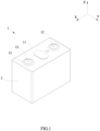
FIG. 1 is a schematic view of a secondary battery according to the present invention. -
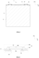
FIG. 2 is a cross-sectional view of the secondary battery according to the present invention. -
FIG. 3 is an enlarged view ofFIG. 2 indicated by a block. -
FIG. 4 is a view of an electrode terminal ofFIG. 3 . -
FIG. 5 is an enlarged view ofFIG. 4 indicated by a block. -
FIG. 6 is a top view of the electrode terminal ofFIG. 4 . -
FIG. 7 is a schematic view of a battery module according to the present invention. -
FIG. 8 is a schematic view showing connection of the secondary battery with a busbar, according to the present invention. - Reference numerals in figures are represented as follows:
- 1 cap assembly
- 11 cap plate
- 111 terminal hole
- 12 electrode terminal
- 121 outer surface
- 121a first region
- 121b second region
- 122 positioning hole
- 122a first portion
- 122b second portion
- 122c first peripheral surface
- 122d second peripheral surface
- 122e third portion
- 122f third peripheral surface
- 122g bottom surface
- 123 first terminal plate
- 124 second terminal plate
- 13 fixing member
- 131 fixing piece
- 132 insulating member
- 14 connecting piece
- 141 bulging portion
- 2 electrode assembly
- 3 case
- 4 busbar
- 41 through hole
- X length direction
- Y width direction
- Z height direction
- To make the object, technical solutions and advantages of the present invention more apparent, hereinafter the present invention will be further described in detail in combination with the accompanying figures and the embodiments. It should be understood that the specific embodiments described herein are merely used to explain the present invention but are not intended to limit the present invention, which is defined by the claims.
- In the description of the present invention, unless otherwise specifically defined and limited, the terms "first", "second" and "third" are only used for illustrative purposes and are not to be construed as expressing or implying a relative importance. The term "plurality" is two or more. Unless otherwise defined or described, the term "connect" should be broadly interpreted, for example, the term "connect" can be "fixedly connect", "detachably connect", "integrally connect", "electrically connect" or "signal connect". The term "connect" also can be "directly connect" or "indirectly connect via a medium". For the persons skilled in the art, the specific meanings of the abovementioned terms in the present invention can be understood according to the specific situation.
- In the description of the present invention, it should be understood that spatially relative terms, such as "above", "below" and the like, are described based on orientations illustrated in the figures, but are not intended to limit the embodiments of the present invention. Hereinafter the present invention will be further described in detail in combination with the exemplary embodiments and the figures.
- Referring to
FIG. 7 , a battery module of the present invention may include a plurality of secondary batteries. The secondary batteries may be columnar prismatic lithium-ion batteries. The plurality of secondary batteries may be arranged sequentially in a width direction Y. - The battery module may further include an end plate and a side plate. The end plate is provided as two in number and the two end plates are respectively provided to both ends of the plurality of secondary batteries in the width direction Y. The side plate is provided as two in number and the two side plates are respectively provided to both sides of the plurality of secondary batteries in a length direction X. The end plates and the side plates are connected together to form a rectangular frame, the frame fixes the plurality of secondary batteries.
- Referring to
FIG. 1 andFIG. 2 , the secondary battery of the present invention includes acap assembly 1, anelectrode assembly 2 and acase 3. - The
electrode assembly 2 is a core member for achieving charge and discharge function of the secondary battery. Theelectrode assembly 2 includes a positive electrode plate, a negative electrode plate and a separator, the separator separates the positive electrode plate and the negative electrode plate. The positive electrode plate includes a positive current collector and a positive active material layer coated on a surface of the positive current collector, the positive current collector may be an aluminum foil, the positive active material layer includes a ternary material, lithium manganese oxide or lithium iron phosphate. The negative electrode plate includes a negative current collector and a negative active material layer coated on a surface of the negative current collector, the negative current collector may be a copper foil, the negative active material layer includes graphite or silicon. - The
electrode assembly 2 may be a winding structure. Specifically, both the positive electrode plate and the negative electrode plate each are provided as one in number, and the positive electrode plate and the negative electrode plate are belt-shaped structures. The positive electrode plate, the separator and the negative electrode plate are sequentially stacked and wound to two or more turns to form theelectrode assembly 2. In the manufacturing process of theelectrode assembly 2, theelectrode assembly 2 may be firstly wound into a hollow cylindrical structure, and then theelectrode assembly 1 is pressed to a flat shape after winding. - Alternatively, the
electrode assembly 2 may be a laminated structure. Specifically, the positive electrode plate is provided as plurality in number, the negative electrode plate is provided as plurality in number, the plurality of positive electrode plates and negative electrode plates are alternately laminated, the separator separates the positive electrode plates and the negative electrode plates. - The
case 3 may have a hexahedron shape or other shape. A receiving cavity is formed inside thecase 3 to receive theelectrode assembly 2 and an electrolyte. An opening is formed at an end of thecase 3, and theelectrode assembly 2 is placed into the receiving cavity of thecase 3 via the opening. Thecase 3 may be made of a conductive metal, in some examples, thecase 3 is made of aluminum or aluminum alloy. - The
cap assembly 1 includes acap plate 11 and anelectrode terminal 12. Thecap plate 11 is provided to thecase 3 and covers the opening of thecase 3, thereby sealing theelectrode assembly 2 within thecase 3. Thecap plate 11 may be a metal plate and connected with thecase 3 by welding. - The
cap plate 11 is provided with twoterminal holes 111 which pass through thecap plate 11. Theelectrode terminal 12 is provided as two in number and provided on an upper side of thecap plate 11 in a height direction Z, that is, a side of thecap plate 11 away from theelectrode assembly 2. Eachelectrode terminal 12 covers one correspondingterminal hole 111. A sealing ring is provided between thecap plate 11 and theelectrode terminal 12, and the sealing of theterminal hole 111 is achieved by compressing the sealing ring. - The
cap assembly 1 further includes a fixingmember 13 and a connectingpiece 14, the fixingmember 13 fixes theelectrode terminal 12 on thecap plate 11. The connectingpiece 14 is provided as two in number, one connectingpiece 14 connects oneelectrode terminal 12 and the positive electrode plate of theelectrode assembly 2, and the other connectingpiece 14 connects theother electrode terminal 12 and the negative electrode plate of theelectrode assembly 2. The connectingpiece 14 may be provided with a bulgingportion 141, the bulgingportion 141 extends into theterminal hole 111 and is connected with theelectrode terminal 12. - In the battery module, the plurality of secondary batteries may be connected together via the
busbar 4. Referring toFIG. 7 , one end of thebusbar 4 is connected to theelectrode terminal 12 of one secondary battery, and the other end of thebusbar 4 is connected to theelectrode terminal 12 of the other secondary battery, thereby connecting the two secondary batteries in series or in parallel. - The
busbar 4 may be fixed to theelectrode terminal 12 by laser welding. When welding, the laser acts on a surface of thebusbar 4, if the position of thebusbar 4 is deviated, it will lead to laser misalignment and poor welding; more seriously, the misaligned laser may directly act on thecap plate 11, causing thecap plate 11 to be fuse through, causing a safety hazard. - The
electrode terminal 12 has anouter surface 121 at an end away from thecap plate 11. In some examples, theelectrode terminal 12 has apositioning hole 122, thepositioning hole 122 is recessed with respect to theouter surface 121 of theelectrode terminal 12. Correspondingly, thebusbar 4 has a throughhole 41 aligned with thepositioning hole 122 of theelectrode terminal 12 in the height direction Z. A size of the throughhole 41 is larger than a size of thepositioning hole 122. - When welding, firstly the
busbar 4 is placed above theelectrode terminal 12 to make the throughhole 41 and thepositioning hole 122 of theelectrode terminal 12 aligned with each other in the height direction Z, and expose thepositioning hole 122 to the throughhole 4. And then thepositioning hole 122 is positioned by using a CCD image sensor. - Specifically, a laser welding device has a CCD taking image and capturing function for finding the location of the desired welding. In Charge Coupled Device (CCD) image sensor, CCD is made of a semiconductor material which is highly light sensitive, converts light into electric charge and converts it into a digital signal through an analog-to-digital converter chip. The digital signal is compressed and then saved by a flash memory or a built-in hard disk card inside a camera, so that the data is easily transmitted to the computer, and the image may be modified as needed and imagination by means of computer processing. The CCD consists of many light sensitive units which are usually mega-pixel units. When the surface of CCD is illuminated by light, a plurality of light sensitive units reflect the electric charges on the components, and signals generated by all the light sensitive units are collected together to form a complete image. The
positioning hole 122 is recessed inwardly with respect to theouter surface 121, and therefore, an outline of thepositioning hole 122 is displayed in the CCD. Through the computer algorithm, a geometric center of thepositioning hole 122 is found, and a welding track is calculated from the geometric center. Finally, the laser welding device performs welding along the calculated welding track. - Therefore, in the present invention, the
positioning hole 122 helps to improve the positioning accuracy between theelectrode terminal 12 and thebusbar 4, and improve the welding strength. - However, if the
positioning hole 122 is provided as a cylindrical hole, in the image taken by the CCD, a boundary between thepositioning hole 122 and theouter surface 121 is a thin line; meanwhile, thebusbar 4 may shield a part of thepositioning hole 122 due to tolerance. Therefore, the outline of thepositioning hole 122 will be not obvious in the CCD, and a proportion of failure by CCD positioning is high, and there is still a risk of welding failure. - Therefore, in some examples, referring to
FIG. 4 and FIG. 5 , thepositioning hole 122 includes afirst portion 122a and asecond portion 122b, thesecond portion 122b is positioned at a side of thefirst portion 122a away from theouter surface 121. A section of thefirst portion 122a parallel to a central axis of thepositioning hole 122 is trapezoidal. Thesecond portion 122b has a shape different from thefirst portion 122a. A size of thefirst portion 122a gradually decreases in a direction away from theouter surface 121, and a minimum size of thefirst portion 122a is greater than or equal to a size of thesecond portion 122b. - In the present invention, the
first portion 122a is generally a hole which has a large diameter at an outer side and a small diameter at an inner side and has a circular truncated cone shape. Thefirst portion 122a has a firstperipheral surface 122c, thesecond portion 122b has a secondperipheral surface 122d, and the firstperipheral surface 122c is connected with the secondperipheral surface 122d. Thepositioning hole 122 is a blind hole, a lower end of thesecond portion 122b in the height direction Z further has abottom surface 122g. - Compared with a straight hole, the first
peripheral surface 122c of thefirst portion 122a is shown as a ring-shaped region in the image taken by the CCD, and has a large width, which may increase the range of capturing of the CCD. Also, the firstperipheral surface 122c is inclined at an angle with respect to the outer surface. 121, so in the image taken by the CCD, the firstperipheral surface 122c and theouter surface 121 have different color depths, which is convenient for the CCD to find the geometric center of the positioning hole 122 (that is the central axis of the positioning hole 122). - In addition, the
positioning hole 122 has thesecond portion 122b with a smaller size. By configuration of thesecond portion 122b, the depth of thepositioning hole 122 is increased, and the contrast between thefirst portion 122a and thesecond portion 122b is increased, further improving the capability of the CCD to capture the firstperipheral surface 122c. The CCD accurately calculates the geometric center of thepositioning hole 122 according to the outline of the firstperipheral surface 122c captured. - In conclusion, the present invention makes the CCD device accurately calculate the geometric center of the
positioning hole 122 by the configuration of thepositioning hole 122 with a specific shape, improve the positioning accuracy between theelectrode terminal 12 and thebusbar 4, and avoid the laser acting on thecap plate 11, thereby improving the welding strength. - Because the first
peripheral surface 122c has a larger width and a darker color in the image taken by the CCD, therefore, even through thebusbar 4 shields a part of thepositioning hole 122 due to the tolerance, the positioning of the CCD is not affected. That is, the throughhole 41 does not need to completely expose the firstperipheral surface 122c. Certainly, in order to ensure the positioning accuracy of the CCD, according to the present invention, a ratio of an exposed area of the firstperipheral surface 122c to a total area of the firstperipheral surface 122c is greater than 2/3. If an area of the firstperipheral surface 122c shielded by thebusbar 4 is more than 1/3 in proportion, even through the firstperipheral surface 122c in the image taken by the CCD has the larger width and darker color, the positioning may fail. - Referring to
FIG. 5 , an angle between the firstperipheral surface 122c and theouter surface 121 is a. When the depth of thefirst portion 122a in the height direction Z is constant, the larger the value of α is, the smaller the inclination of the firstperipheral surface 122 is, and the smaller the difference in color between the firstperipheral surface 122c and theouter surface 121 in the image taken by the CCD is; however, in the image taken by the CCD, the larger the width of the firstperipheral surface 122c is. The smaller the value of α is, the greater the degree of inclination of the firstperipheral surface 122, and in the image taken by the CCD, the greater the difference in color between the firstperipheral surface 122c and theouter surface 121 is; certainly, in the image taken by the CCD, the smaller the width of the firstperipheral surface 122c is. Therefore, in some examples, the value of α is from 135 degrees to 175 degrees, here, the width and color depth of the firstperipheral surface 122c in the image taken by the CCD may considered at the same time, and the positioning function is improved. - The
positioning hole 122 further includes athird portion 122e, thethird portion 122e is cylindrical and is positioned between thefirst portion 122a and thesecond portion 122b. Thethird portion 122e has a thirdperipheral surface 122f which is cylindrical, the thirdperipheral surface 122f connects the firstperipheral surface 122c and the secondperipheral surface 122d. Thethird portion 122e is a hole with the constant diameter. By configuration of thethird portion 122e, a distance between thefirst portion 122a and thesecond portion 122b is increased, the light reflection is reduced, the contrast between the firstperipheral surface 122c and the secondperipheral surface 122d in the image is improved, and the positioning function is improved. - The
outer surface 121 includes afirst region 121a and asecond region 121b, thefirst region 121a surrounds the firstperipheral surface 122c and is connected with the firstperipheral surface 122c, and thesecond region 121b surrounds thefirst region 121a and is connected with thefirst region 121a. A roughness of thefirst region 121a is greater than a roughness of the firstperipheral surface 122c. - In the present invention, by increasing the roughness of the
first region 121a, the contrast between thefirst region 121a and the firstperipheral surface 122c in the image is improved, so that the firstperipheral surface 122c is captured by CCD and the positioning performance is improved. Certainly, in order for the CCD to capture thefirst region 121a, the throughhole 41 should expose at least part of thefirst region 121a. - The roughness of the
first region 121a is from 1µm to 14µm. If the roughness of thefirst region 121a is less than 1µm, the influence of the roughness of thefirst region 121a on the contrast between thefirst region 121a and the firstperipheral surface 122c in the image is small. If the roughness of thefirst region 121a is greater than 14µm, the flatness of thefirst region 121a may be too poor; when thebusbar 4 is attached to thefirst region 121a and thesecond region 121b, the stability of thebusbar 4 is poor. In some examples, the roughness of thefirst region 121a is from 1.2µm to 7µm. - The
busbar 4 may be welded to thesecond region 121b of theouter surface 121. If the roughness of thesecond region 121b is too large, when thebusbar 4 is welded to thesecond region 121b, it is easy to cause poor welding. Therefore, a roughness of thesecond region 121b is less than the roughness of thefirst region 121a. - A size of the
second portion 122b gradually decreases in a direction away from theouter surface 121. The secondperipheral surface 122d of thesecond portion 122b is a circular arc surface. - In the present invention, the
electrode terminal 12 is provided to a side of thecap plate 11, theelectrode terminal 12 does not need to pass through theterminal hole 111 of thecap plate 11, therefore, theelectrode terminal 12 may have an smaller thickness. However, in the working process of the secondary battery, gas will be generated inside thecase 3, and the gas exerts pressure on thecap plate 11 and theelectrode terminal 12. Since the thickness of theelectrode terminal 12 is small, theelectrode terminal 12 is deformed by the pressure of the gas. However, the pressure is concentrated at thepositioning hole 122 of theelectrode terminal 12, and if the pressure of the gas is too large, theelectrode terminal 12 may be broken. In the present invention, a round corner is provided at the bottom of thepositioning hole 122 to form the secondperipheral surface 122d which is a circular arc surface. The secondperipheral surface 122d which is a circular arc surface disperses the stress, and reduce the risk of break of theelectrode terminal 12. - The
cap assembly 1 further includes the fixingmember 13, the fixingmember 13 connects thecap plate 11 and theelectrode terminal 12, an edge of theelectrode terminal 12 is positioned between the fixingmember 13 and thecap plate 11. - The fixing
member 13 may include a fixingpiece 131 and an insulatingmember 132, the fixingpiece 131 may be fixed,to thecap plate 11 by welding, and the insulatingmember 132 is integrated to the fixingpiece 131 and separates the fixingpiece 131 and theelectrode terminal 12. The insulatingmember 132 may surround theelectrode terminal 12, and the edge of theelectrode terminal 12 is positioned between the insulatingmember 132 and thecap plate 11. The insulatingmember 132 presses theelectrode terminal 12 against thecap plate 11 to prevent theelectrode terminal 12 from being detached from thecap plate 11. - Certainly, since the edge of the
electrode terminal 12 is limited by the insulatingmember 132, a central region of theelectrode terminal 12 provided with thepositioning hole 122 is easily deformed to bulge by the pressure of the gas. If the secondperipheral surface 122d which is a circular arc surface is not provided, theelectrode terminal 12 is easily broken by the pressure of the gas. - The
electrode terminal 12 electrically connected with the negative electrode may be a metal composite plate. Specifically, theelectrode terminal 12 may include a firstterminal plate 123 and a secondterminal plate 124. In some examples, the firstterminal plate 123 is made of aluminum and the secondterminal plate 124 is made of copper. The firstterminal plate 123 and the secondterminal plate 124 is compounded as one by a cold rolling method, a hot rolling method, an explosion compound method or an explosive rolling method and the like in some examples. The firstterminal plate 123 is positioned to a side of the secondterminal plate 124 away from thecap plate 11. - The use of the second
terminal plate 124 which is made of copper facilitate the connection of the secondterminal plate 124 with the negative electrode plate. The material of thebusbar 4 is usually aluminum, and the firstterminal plate 123 made of aluminum facilitate the welding of the firstterminal plate 123 and thebusbar 4. - The
positioning hole 122 is formed to the firstterminal plate 123. That is, the depth of thepositioning hole 122 is less than a thickness of the firstterminal plate 123. This avoids the compounded interface of the firstterminal plate 123 and the secondterminal plate 124 from being exposed, and prevent the firstterminal plate 123 and the secondterminal plate 124 from being separated.
Claims (12)
- A battery module, comprising a secondary battery and a busbar (4),the secondary battery comprising an electrode assembly (2), a case (3) and a cap assembly (1);the electrode assembly (2) being received in the case (3);the cap assembly (1) comprising a cap plate (11) and an electrode terminal (12);the cap plate (11) being connected to the case (3), the cap plate (11) being provided with a terminal hole (111),the electrode terminal (12) being provided to a side of the cap plate (11) away from the electrode assembly (2) and covering the terminal hole (111);the electrode terminal (12) comprising an outer surface (121);the electrode terminal (12) comprising a positioning hole (122), the positioning hole (122) being recessed with respect to the outer surface (121) of the electrode terminal (12) and comprising a first portion (122a) and a second portion (122b), the first portion (122a) having a first peripheral surface (122c), the second portion (122b) being positioned to a side of the first portion (122a) away from the outer surface (121);a section of the first portion (122a) parallel to a central axis of the positioning hole (122) being trapezoidal;a size of the first portion (122a) gradually decreasing in a direction of the first portion (122a) close to the second portion (122b), and a minimum size of the first portion (122a) being greater than or equal to a size of the second portion (122b);the busbar (4) being connected to the electrode terminal (12);characterized in thatthe busbar (4) comprising a through hole (41) aligned with the positioning hole (122) of the electrode terminal (12) in a height direction (Z);the through hole (41) exposing the first peripheral surface (122c), and a ratio of an exposed area of the first peripheral surface (122c) to a total area of the first peripheral surface (122c) being greater than 2/3.
- The battery module according to claim 1, wherein an angle between the first peripheral surface (122c) and the outer surface (121) is from 135 degrees to 175 degrees.
- The battery module according to claim 1 or 2, whereinthe outer surface (121) comprises a first region (121a) and a second region (121b), the first region (121a) surrounds the first peripheral surface (122c) and is connected with the first peripheral surface (122c), and the second region (121b) surrounds the first region (121a) and is connected with the first region (121a);a roughness of the first region (121a) is greater than a roughness of the first peripheral surface (122c).
- The battery module according to claim 3, wherein the roughness of the first region (121a) is from 1µm to 14µm.
- The battery module according to any one of claims 1-4, whereina size of the second portion (122b) gradually decreases in a direction of the second portion (122b) away from the first portion (122a);the second portion (122b) has a second peripheral surface (122d), the second peripheral surface (122d) is a circular arc surface.
- The battery module according to any one of claims 1-5, wherein a shape of the second portion (122b) is different from a shape of the first portion (122a).
- The battery module according to any one of claims 1-6, wherein the positioning hole (122) further comprises a third portion (122e), the third portion (122e) is cylindrical and is positioned between the first portion (122a) and the second portion (122b).
- The battery module according to any one of claims 1-7, wherein the electrode terminal (12) comprises a first terminal plate (123) and a second terminal plate (124), the first terminal plate (123) is positioned to a side of the second terminal plate (124) away from the cap plate (11);the first terminal plate (123) is made of aluminum and the second terminal plate (124) is made of copper;the positioning hole (122) is formed to the first terminal plate (123), and a depth of the positioning hole (122) is less than a thickness of the first terminal plate (123).
- The battery module according to any one of claims 1-8, wherein the cap assembly (1) further comprises a fixing member (13), the fixing member (13) connects the cap plate (11) and the electrode terminal (12), an edge of the electrode terminal (12) is positioned between the fixing member (13) and the cap plate (11).
- The battery module according to any one of claims 1-9, wherein the cap assembly (1) further comprises a connecting piece (14), the connecting piece (14) is provided with a bulging portion (141), the bulging portion (141) extends into the terminal hole (111) and is connected with the electrode terminal (12).
- The battery module according to any one of claims 1-10, wherein the cap assembly (1) further comprises a sealing ring, the sealing ring is provided between the cap plate (11) and the electrode terminal (12).
- The battery module according to claim 3, wherein the busbar (4) is welded to the second region (121b) of the outer surface (121), the through hole (41) exposes at least part of the first region (121a).
Applications Claiming Priority (1)
| Application Number | Priority Date | Filing Date | Title |
|---|---|---|---|
| CN201920589861.6U CN209880723U (en) | 2019-04-26 | 2019-04-26 | Battery module, secondary battery and top cover assembly thereof |
Publications (2)
| Publication Number | Publication Date |
|---|---|
| EP3731297A1 EP3731297A1 (en) | 2020-10-28 |
| EP3731297B1 true EP3731297B1 (en) | 2025-02-12 |
Family
ID=68962490
Family Applications (1)
| Application Number | Title | Priority Date | Filing Date |
|---|---|---|---|
| EP19220159.8A Active EP3731297B1 (en) | 2019-04-26 | 2019-12-31 | Battery module |
Country Status (6)
| Country | Link |
|---|---|
| US (2) | US20200343522A1 (en) |
| EP (1) | EP3731297B1 (en) |
| JP (1) | JP7239728B2 (en) |
| CN (1) | CN209880723U (en) |
| HU (1) | HUE071028T2 (en) |
| WO (1) | WO2020215939A1 (en) |
Families Citing this family (8)
| Publication number | Priority date | Publication date | Assignee | Title |
|---|---|---|---|---|
| CN209880723U (en) * | 2019-04-26 | 2019-12-31 | 宁德时代新能源科技股份有限公司 | Battery module, secondary battery and top cover assembly thereof |
| JP7446202B2 (en) * | 2020-11-16 | 2024-03-08 | プライムプラネットエナジー&ソリューションズ株式会社 | Batteries and battery manufacturing methods |
| DE102020216323A1 (en) | 2020-12-18 | 2022-06-23 | Robert Bosch Gesellschaft mit beschränkter Haftung | Method and device for electrically contacting cells of a battery |
| CN112713341B (en) * | 2020-12-31 | 2023-04-28 | 中创新航科技股份有限公司 | Cover plate assembly and preparation method thereof, battery and battery module |
| CN116897457A (en) * | 2021-10-20 | 2023-10-17 | 宁德时代新能源科技股份有限公司 | End cover components, battery cells, batteries and electrical equipment |
| KR102959689B1 (en) * | 2021-10-28 | 2026-04-29 | 주식회사 엘지에너지솔루션 | Electrode lead for electrochemical device and electrochemical device comprising the same |
| CN113790673B (en) * | 2021-11-16 | 2022-04-01 | 江苏时代新能源科技有限公司 | A kind of battery, electric device, welding deviation detection device and method |
| WO2026028955A1 (en) * | 2024-07-31 | 2026-02-05 | 株式会社Gsユアサ | Power storage device |
Family Cites Families (20)
| Publication number | Priority date | Publication date | Assignee | Title |
|---|---|---|---|---|
| JP2002124218A (en) * | 2000-10-16 | 2002-04-26 | Toshiba Battery Co Ltd | Cylindrical battery |
| JP4236826B2 (en) * | 2001-04-02 | 2009-03-11 | 三菱電機株式会社 | Power module and manufacturing method thereof |
| JP4452846B2 (en) * | 2004-04-02 | 2010-04-21 | Dowaメタルテック株式会社 | Metal-ceramic bonding substrate and manufacturing method thereof |
| JP2006019220A (en) * | 2004-07-05 | 2006-01-19 | Japan Storage Battery Co Ltd | Battery |
| KR20110133257A (en) * | 2010-06-04 | 2011-12-12 | 에스비리모티브 주식회사 | Secondary battery |
| US9673430B2 (en) * | 2012-10-26 | 2017-06-06 | Sanyo Electric Co., Ltd. | Power source device, electric vehicle comprising power source device, accumulator device |
| US9350127B2 (en) * | 2014-03-24 | 2016-05-24 | Ford Global Technologies, Llc | Self-locating busbar assembly and alignment method |
| KR102368085B1 (en) | 2015-03-03 | 2022-02-24 | 삼성에스디아이 주식회사 | Rechargeable battery having connecting member |
| CN205723741U (en) * | 2016-05-24 | 2016-11-23 | 宁德时代新能源科技股份有限公司 | Cell and battery modules |
| CN105845851B (en) | 2016-06-07 | 2018-07-17 | 宁德时代新能源科技股份有限公司 | Power battery top cover and power battery thereof |
| KR102454791B1 (en) * | 2017-06-13 | 2022-10-14 | 삼성에스디아이 주식회사 | Secondary battery having positive electrode terminal and membrane-integrated cap plate |
| JP6565973B2 (en) * | 2017-06-29 | 2019-08-28 | 日亜化学工業株式会社 | Mounting component, semiconductor device using the same, and manufacturing method thereof |
| CN207183342U (en) * | 2017-07-04 | 2018-04-03 | 宁德时代新能源科技股份有限公司 | battery module |
| CN207353302U (en) | 2017-09-18 | 2018-05-11 | 宁德时代新能源科技股份有限公司 | Power battery cap assembly, power battery and battery modules |
| CN109659454B (en) * | 2017-10-10 | 2020-11-10 | 宁德时代新能源科技股份有限公司 | Top cover assembly of secondary battery and secondary battery |
| JP7027790B2 (en) * | 2017-10-17 | 2022-03-02 | 三洋電機株式会社 | How to manufacture a secondary battery |
| US10763466B2 (en) * | 2018-03-09 | 2020-09-01 | Contemporary Amperex Technology Co., Limited | Top cap assembly of a secondary battery, and secondary battery |
| CN208507744U (en) * | 2018-06-27 | 2019-02-15 | 中航锂电(洛阳)有限公司 | Battery connecting piece and battery |
| CN208622794U (en) * | 2018-08-01 | 2019-03-19 | 宁德时代新能源科技股份有限公司 | Secondary battery and its top cover assembly |
| CN209880723U (en) * | 2019-04-26 | 2019-12-31 | 宁德时代新能源科技股份有限公司 | Battery module, secondary battery and top cover assembly thereof |
-
2019
- 2019-04-26 CN CN201920589861.6U patent/CN209880723U/en active Active
- 2019-12-30 US US16/730,854 patent/US20200343522A1/en not_active Abandoned
- 2019-12-31 EP EP19220159.8A patent/EP3731297B1/en active Active
- 2019-12-31 HU HUE19220159A patent/HUE071028T2/en unknown
-
2020
- 2020-03-19 WO PCT/CN2020/080212 patent/WO2020215939A1/en not_active Ceased
- 2020-03-19 JP JP2021551825A patent/JP7239728B2/en active Active
- 2020-12-30 US US17/138,586 patent/US11258143B2/en active Active
Also Published As
| Publication number | Publication date |
|---|---|
| US11258143B2 (en) | 2022-02-22 |
| US20200343522A1 (en) | 2020-10-29 |
| EP3731297A1 (en) | 2020-10-28 |
| WO2020215939A1 (en) | 2020-10-29 |
| HUE071028T2 (en) | 2025-07-28 |
| CN209880723U (en) | 2019-12-31 |
| JP7239728B2 (en) | 2023-03-14 |
| US20210119308A1 (en) | 2021-04-22 |
| JP2022522494A (en) | 2022-04-19 |
Similar Documents
| Publication | Publication Date | Title |
|---|---|---|
| US11258143B2 (en) | Battery module, secondary battery and cap assembly thereof | |
| EP2388847B1 (en) | Secondary battery comprising first and second collector plates that are enmeshed together | |
| EP3852165B1 (en) | Secondary battery and manufacturing method for secondary battery | |
| US11271274B2 (en) | Secondary battery | |
| US12244025B2 (en) | Secondary battery and battery module | |
| EP2325924A1 (en) | Secondary battery comprising a short circuit inducing member | |
| EP3787086B1 (en) | Secondary battery | |
| EP3703160B1 (en) | Secondary battery | |
| EP3764418A1 (en) | Cap assembly and secondary battery | |
| EP3926742A1 (en) | Top cover assembly, secondary battery, battery module and device | |
| EP4080658B1 (en) | Safety apparatus and battery | |
| JP7374204B2 (en) | secondary battery | |
| EP4030537B1 (en) | Secondary battery and manufacturing method therefor, battery module, and apparatus | |
| KR20180110086A (en) | Power storage device and manufacturing method thereof | |
| EP3920268B1 (en) | Secondary cell | |
| CN210403894U (en) | Secondary battery | |
| EP4723316A2 (en) | Cylindrical battery, battery module, and electric device | |
| CN219123336U (en) | Battery assembly | |
| CN217009504U (en) | Battery with a battery cell | |
| CN116210122B (en) | Electrochemical devices and electrical equipment | |
| CN217062447U (en) | Battery with a battery cell | |
| EP4142039A1 (en) | Secondary battery | |
| KR20260001350A (en) | Secondary battery |
Legal Events
| Date | Code | Title | Description |
|---|---|---|---|
| PUAI | Public reference made under article 153(3) epc to a published international application that has entered the european phase |
Free format text: ORIGINAL CODE: 0009012 |
|
| STAA | Information on the status of an ep patent application or granted ep patent |
Free format text: STATUS: REQUEST FOR EXAMINATION WAS MADE |
|
| 17P | Request for examination filed |
Effective date: 20191231 |
|
| AK | Designated contracting states |
Kind code of ref document: A1 Designated state(s): AL AT BE BG CH CY CZ DE DK EE ES FI FR GB GR HR HU IE IS IT LI LT LU LV MC MK MT NL NO PL PT RO RS SE SI SK SM TR |
|
| AX | Request for extension of the european patent |
Extension state: BA ME |
|
| REG | Reference to a national code |
Ref country code: DE Ref legal event code: R079 Free format text: PREVIOUS MAIN CLASS: H01M0002040000 Ipc: H01M0050147000 Ref document number: 602019065724 Country of ref document: DE |
|
| GRAP | Despatch of communication of intention to grant a patent |
Free format text: ORIGINAL CODE: EPIDOSNIGR1 |
|
| STAA | Information on the status of an ep patent application or granted ep patent |
Free format text: STATUS: GRANT OF PATENT IS INTENDED |
|
| RIC1 | Information provided on ipc code assigned before grant |
Ipc: H01M 50/566 20210101ALN20240809BHEP Ipc: H01M 50/55 20210101ALN20240809BHEP Ipc: H01M 50/176 20210101ALI20240809BHEP Ipc: H01M 50/147 20210101AFI20240809BHEP |
|
| RAP1 | Party data changed (applicant data changed or rights of an application transferred) |
Owner name: CONTEMPORARY AMPEREX TECHNOLOGY(HONG KONG) LIMITED |
|
| INTG | Intention to grant announced |
Effective date: 20240911 |
|
| GRAS | Grant fee paid |
Free format text: ORIGINAL CODE: EPIDOSNIGR3 |
|
| GRAA | (expected) grant |
Free format text: ORIGINAL CODE: 0009210 |
|
| STAA | Information on the status of an ep patent application or granted ep patent |
Free format text: STATUS: THE PATENT HAS BEEN GRANTED |
|
| AK | Designated contracting states |
Kind code of ref document: B1 Designated state(s): AL AT BE BG CH CY CZ DE DK EE ES FI FR GB GR HR HU IE IS IT LI LT LU LV MC MK MT NL NO PL PT RO RS SE SI SK SM TR |
|
| REG | Reference to a national code |
Ref country code: GB Ref legal event code: FG4D |
|
| REG | Reference to a national code |
Ref country code: CH Ref legal event code: EP |
|
| P01 | Opt-out of the competence of the unified patent court (upc) registered |
Free format text: CASE NUMBER: APP_1251/2025 Effective date: 20250109 |
|
| REG | Reference to a national code |
Ref country code: DE Ref legal event code: R096 Ref document number: 602019065724 Country of ref document: DE |
|
| REG | Reference to a national code |
Ref country code: IE Ref legal event code: FG4D |
|
| REG | Reference to a national code |
Ref country code: NL Ref legal event code: MP Effective date: 20250212 |
|
| PG25 | Lapsed in a contracting state [announced via postgrant information from national office to epo] |
Ref country code: RS Free format text: LAPSE BECAUSE OF FAILURE TO SUBMIT A TRANSLATION OF THE DESCRIPTION OR TO PAY THE FEE WITHIN THE PRESCRIBED TIME-LIMIT Effective date: 20250512 |
|
| PG25 | Lapsed in a contracting state [announced via postgrant information from national office to epo] |
Ref country code: FI Free format text: LAPSE BECAUSE OF FAILURE TO SUBMIT A TRANSLATION OF THE DESCRIPTION OR TO PAY THE FEE WITHIN THE PRESCRIBED TIME-LIMIT Effective date: 20250212 |
|
| PG25 | Lapsed in a contracting state [announced via postgrant information from national office to epo] |
Ref country code: PL Free format text: LAPSE BECAUSE OF FAILURE TO SUBMIT A TRANSLATION OF THE DESCRIPTION OR TO PAY THE FEE WITHIN THE PRESCRIBED TIME-LIMIT Effective date: 20250212 |
|
| PG25 | Lapsed in a contracting state [announced via postgrant information from national office to epo] |
Ref country code: ES Free format text: LAPSE BECAUSE OF FAILURE TO SUBMIT A TRANSLATION OF THE DESCRIPTION OR TO PAY THE FEE WITHIN THE PRESCRIBED TIME-LIMIT Effective date: 20250212 |
|
| REG | Reference to a national code |
Ref country code: LT Ref legal event code: MG9D |
|
| PG25 | Lapsed in a contracting state [announced via postgrant information from national office to epo] |
Ref country code: IS Free format text: LAPSE BECAUSE OF FAILURE TO SUBMIT A TRANSLATION OF THE DESCRIPTION OR TO PAY THE FEE WITHIN THE PRESCRIBED TIME-LIMIT Effective date: 20250612 Ref country code: NO Free format text: LAPSE BECAUSE OF FAILURE TO SUBMIT A TRANSLATION OF THE DESCRIPTION OR TO PAY THE FEE WITHIN THE PRESCRIBED TIME-LIMIT Effective date: 20250512 |
|
| PG25 | Lapsed in a contracting state [announced via postgrant information from national office to epo] |
Ref country code: NL Free format text: LAPSE BECAUSE OF FAILURE TO SUBMIT A TRANSLATION OF THE DESCRIPTION OR TO PAY THE FEE WITHIN THE PRESCRIBED TIME-LIMIT Effective date: 20250212 |
|
| PG25 | Lapsed in a contracting state [announced via postgrant information from national office to epo] |
Ref country code: HR Free format text: LAPSE BECAUSE OF FAILURE TO SUBMIT A TRANSLATION OF THE DESCRIPTION OR TO PAY THE FEE WITHIN THE PRESCRIBED TIME-LIMIT Effective date: 20250212 |
|
| PG25 | Lapsed in a contracting state [announced via postgrant information from national office to epo] |
Ref country code: LV Free format text: LAPSE BECAUSE OF FAILURE TO SUBMIT A TRANSLATION OF THE DESCRIPTION OR TO PAY THE FEE WITHIN THE PRESCRIBED TIME-LIMIT Effective date: 20250212 Ref country code: PT Free format text: LAPSE BECAUSE OF FAILURE TO SUBMIT A TRANSLATION OF THE DESCRIPTION OR TO PAY THE FEE WITHIN THE PRESCRIBED TIME-LIMIT Effective date: 20250612 |
|
| PG25 | Lapsed in a contracting state [announced via postgrant information from national office to epo] |
Ref country code: BG Free format text: LAPSE BECAUSE OF FAILURE TO SUBMIT A TRANSLATION OF THE DESCRIPTION OR TO PAY THE FEE WITHIN THE PRESCRIBED TIME-LIMIT Effective date: 20250212 Ref country code: GR Free format text: LAPSE BECAUSE OF FAILURE TO SUBMIT A TRANSLATION OF THE DESCRIPTION OR TO PAY THE FEE WITHIN THE PRESCRIBED TIME-LIMIT Effective date: 20250513 |
|
| REG | Reference to a national code |
Ref country code: HU Ref legal event code: AG4A Ref document number: E071028 Country of ref document: HU |
|
| REG | Reference to a national code |
Ref country code: AT Ref legal event code: MK05 Ref document number: 1766994 Country of ref document: AT Kind code of ref document: T Effective date: 20250212 |
|
| PG25 | Lapsed in a contracting state [announced via postgrant information from national office to epo] |
Ref country code: SE Free format text: LAPSE BECAUSE OF FAILURE TO SUBMIT A TRANSLATION OF THE DESCRIPTION OR TO PAY THE FEE WITHIN THE PRESCRIBED TIME-LIMIT Effective date: 20250212 |
|
| PG25 | Lapsed in a contracting state [announced via postgrant information from national office to epo] |
Ref country code: SM Free format text: LAPSE BECAUSE OF FAILURE TO SUBMIT A TRANSLATION OF THE DESCRIPTION OR TO PAY THE FEE WITHIN THE PRESCRIBED TIME-LIMIT Effective date: 20250212 |
|
| PG25 | Lapsed in a contracting state [announced via postgrant information from national office to epo] |
Ref country code: DK Free format text: LAPSE BECAUSE OF FAILURE TO SUBMIT A TRANSLATION OF THE DESCRIPTION OR TO PAY THE FEE WITHIN THE PRESCRIBED TIME-LIMIT Effective date: 20250212 |
|
| PG25 | Lapsed in a contracting state [announced via postgrant information from national office to epo] |
Ref country code: AT Free format text: LAPSE BECAUSE OF FAILURE TO SUBMIT A TRANSLATION OF THE DESCRIPTION OR TO PAY THE FEE WITHIN THE PRESCRIBED TIME-LIMIT Effective date: 20250212 |
|
| PG25 | Lapsed in a contracting state [announced via postgrant information from national office to epo] |
Ref country code: EE Free format text: LAPSE BECAUSE OF FAILURE TO SUBMIT A TRANSLATION OF THE DESCRIPTION OR TO PAY THE FEE WITHIN THE PRESCRIBED TIME-LIMIT Effective date: 20250212 Ref country code: CZ Free format text: LAPSE BECAUSE OF FAILURE TO SUBMIT A TRANSLATION OF THE DESCRIPTION OR TO PAY THE FEE WITHIN THE PRESCRIBED TIME-LIMIT Effective date: 20250212 |
|
| PG25 | Lapsed in a contracting state [announced via postgrant information from national office to epo] |
Ref country code: RO Free format text: LAPSE BECAUSE OF FAILURE TO SUBMIT A TRANSLATION OF THE DESCRIPTION OR TO PAY THE FEE WITHIN THE PRESCRIBED TIME-LIMIT Effective date: 20250212 |
|
| PG25 | Lapsed in a contracting state [announced via postgrant information from national office to epo] |
Ref country code: SK Free format text: LAPSE BECAUSE OF FAILURE TO SUBMIT A TRANSLATION OF THE DESCRIPTION OR TO PAY THE FEE WITHIN THE PRESCRIBED TIME-LIMIT Effective date: 20250212 |
|
| REG | Reference to a national code |
Ref country code: DE Ref legal event code: R097 Ref document number: 602019065724 Country of ref document: DE |
|
| PLBE | No opposition filed within time limit |
Free format text: ORIGINAL CODE: 0009261 |
|
| STAA | Information on the status of an ep patent application or granted ep patent |
Free format text: STATUS: NO OPPOSITION FILED WITHIN TIME LIMIT |
|
| PGFP | Annual fee paid to national office [announced via postgrant information from national office to epo] |
Ref country code: DE Payment date: 20251212 Year of fee payment: 7 |
|
| PGFP | Annual fee paid to national office [announced via postgrant information from national office to epo] |
Ref country code: GB Payment date: 20251211 Year of fee payment: 7 |
|
| PGFP | Annual fee paid to national office [announced via postgrant information from national office to epo] |
Ref country code: IT Payment date: 20251212 Year of fee payment: 7 |
|
| PGFP | Annual fee paid to national office [announced via postgrant information from national office to epo] |
Ref country code: HU Payment date: 20251209 Year of fee payment: 7 Ref country code: FR Payment date: 20251212 Year of fee payment: 7 |
|
| 26N | No opposition filed |
Effective date: 20251113 |