EP3852165B1 - Secondary battery and manufacturing method for secondary battery - Google Patents
Secondary battery and manufacturing method for secondary battery Download PDFInfo
- Publication number
- EP3852165B1 EP3852165B1 EP19874930.1A EP19874930A EP3852165B1 EP 3852165 B1 EP3852165 B1 EP 3852165B1 EP 19874930 A EP19874930 A EP 19874930A EP 3852165 B1 EP3852165 B1 EP 3852165B1
- Authority
- EP
- European Patent Office
- Prior art keywords
- substrate
- tab
- support plate
- bending
- secondary battery
- Prior art date
- Legal status (The legal status is an assumption and is not a legal conclusion. Google has not performed a legal analysis and makes no representation as to the accuracy of the status listed.)
- Active
Links
- 238000004519 manufacturing process Methods 0.000 title claims description 10
- 238000005452 bending Methods 0.000 claims description 90
- 239000000758 substrate Substances 0.000 claims description 65
- 238000000034 method Methods 0.000 claims description 10
- 239000011149 active material Substances 0.000 description 15
- 230000000712 assembly Effects 0.000 description 9
- 238000000429 assembly Methods 0.000 description 9
- 238000009413 insulation Methods 0.000 description 6
- 238000003466 welding Methods 0.000 description 6
- 238000004804 winding Methods 0.000 description 5
- 239000004743 Polypropylene Substances 0.000 description 4
- 229920001155 polypropylene Polymers 0.000 description 4
- 239000004698 Polyethylene Substances 0.000 description 3
- 229920000573 polyethylene Polymers 0.000 description 3
- 239000002002 slurry Substances 0.000 description 3
- 229910052782 aluminium Inorganic materials 0.000 description 2
- XAGFODPZIPBFFR-UHFFFAOYSA-N aluminium Chemical group [Al] XAGFODPZIPBFFR-UHFFFAOYSA-N 0.000 description 2
- 239000011248 coating agent Substances 0.000 description 2
- 238000000576 coating method Methods 0.000 description 2
- 239000000306 component Substances 0.000 description 2
- 239000004020 conductor Substances 0.000 description 2
- 238000010586 diagram Methods 0.000 description 2
- QHGJSLXSVXVKHZ-UHFFFAOYSA-N dilithium;dioxido(dioxo)manganese Chemical compound [Li+].[Li+].[O-][Mn]([O-])(=O)=O QHGJSLXSVXVKHZ-UHFFFAOYSA-N 0.000 description 2
- 239000011888 foil Substances 0.000 description 2
- GELKBWJHTRAYNV-UHFFFAOYSA-K lithium iron phosphate Chemical compound [Li+].[Fe+2].[O-]P([O-])([O-])=O GELKBWJHTRAYNV-UHFFFAOYSA-K 0.000 description 2
- 229910052751 metal Inorganic materials 0.000 description 2
- 239000002184 metal Substances 0.000 description 2
- -1 polyethylene Polymers 0.000 description 2
- 229910000838 Al alloy Inorganic materials 0.000 description 1
- OKTJSMMVPCPJKN-UHFFFAOYSA-N Carbon Chemical compound [C] OKTJSMMVPCPJKN-UHFFFAOYSA-N 0.000 description 1
- RYGMFSIKBFXOCR-UHFFFAOYSA-N Copper Chemical compound [Cu] RYGMFSIKBFXOCR-UHFFFAOYSA-N 0.000 description 1
- HBBGRARXTFLTSG-UHFFFAOYSA-N Lithium ion Chemical compound [Li+] HBBGRARXTFLTSG-UHFFFAOYSA-N 0.000 description 1
- 230000009286 beneficial effect Effects 0.000 description 1
- 239000011230 binding agent Substances 0.000 description 1
- 239000002131 composite material Substances 0.000 description 1
- 239000006258 conductive agent Substances 0.000 description 1
- 239000011889 copper foil Substances 0.000 description 1
- 239000008358 core component Substances 0.000 description 1
- 238000002788 crimping Methods 0.000 description 1
- 230000000694 effects Effects 0.000 description 1
- 239000003792 electrolyte Substances 0.000 description 1
- 239000010439 graphite Substances 0.000 description 1
- 229910002804 graphite Inorganic materials 0.000 description 1
- 229910001416 lithium ion Inorganic materials 0.000 description 1
- 239000000463 material Substances 0.000 description 1
- 239000007769 metal material Substances 0.000 description 1
- 238000003825 pressing Methods 0.000 description 1
- 229910052710 silicon Inorganic materials 0.000 description 1
- 239000010703 silicon Substances 0.000 description 1
- 239000002904 solvent Substances 0.000 description 1
Images


Classifications
-
- H—ELECTRICITY
- H01—ELECTRIC ELEMENTS
- H01M—PROCESSES OR MEANS, e.g. BATTERIES, FOR THE DIRECT CONVERSION OF CHEMICAL ENERGY INTO ELECTRICAL ENERGY
- H01M4/00—Electrodes
- H01M4/02—Electrodes composed of, or comprising, active material
- H01M4/64—Carriers or collectors
- H01M4/70—Carriers or collectors characterised by shape or form
-
- H—ELECTRICITY
- H01—ELECTRIC ELEMENTS
- H01M—PROCESSES OR MEANS, e.g. BATTERIES, FOR THE DIRECT CONVERSION OF CHEMICAL ENERGY INTO ELECTRICAL ENERGY
- H01M10/00—Secondary cells; Manufacture thereof
- H01M10/05—Accumulators with non-aqueous electrolyte
- H01M10/052—Li-accumulators
-
- H—ELECTRICITY
- H01—ELECTRIC ELEMENTS
- H01M—PROCESSES OR MEANS, e.g. BATTERIES, FOR THE DIRECT CONVERSION OF CHEMICAL ENERGY INTO ELECTRICAL ENERGY
- H01M10/00—Secondary cells; Manufacture thereof
- H01M10/04—Construction or manufacture in general
-
- H—ELECTRICITY
- H01—ELECTRIC ELEMENTS
- H01M—PROCESSES OR MEANS, e.g. BATTERIES, FOR THE DIRECT CONVERSION OF CHEMICAL ENERGY INTO ELECTRICAL ENERGY
- H01M10/00—Secondary cells; Manufacture thereof
- H01M10/04—Construction or manufacture in general
- H01M10/0431—Cells with wound or folded electrodes
-
- H—ELECTRICITY
- H01—ELECTRIC ELEMENTS
- H01M—PROCESSES OR MEANS, e.g. BATTERIES, FOR THE DIRECT CONVERSION OF CHEMICAL ENERGY INTO ELECTRICAL ENERGY
- H01M4/00—Electrodes
- H01M4/02—Electrodes composed of, or comprising, active material
- H01M4/64—Carriers or collectors
- H01M4/70—Carriers or collectors characterised by shape or form
- H01M4/78—Shapes other than plane or cylindrical, e.g. helical
-
- H—ELECTRICITY
- H01—ELECTRIC ELEMENTS
- H01M—PROCESSES OR MEANS, e.g. BATTERIES, FOR THE DIRECT CONVERSION OF CHEMICAL ENERGY INTO ELECTRICAL ENERGY
- H01M50/00—Constructional details or processes of manufacture of the non-active parts of electrochemical cells other than fuel cells, e.g. hybrid cells
- H01M50/10—Primary casings, jackets or wrappings of a single cell or a single battery
- H01M50/102—Primary casings, jackets or wrappings of a single cell or a single battery characterised by their shape or physical structure
- H01M50/103—Primary casings, jackets or wrappings of a single cell or a single battery characterised by their shape or physical structure prismatic or rectangular
-
- H—ELECTRICITY
- H01—ELECTRIC ELEMENTS
- H01M—PROCESSES OR MEANS, e.g. BATTERIES, FOR THE DIRECT CONVERSION OF CHEMICAL ENERGY INTO ELECTRICAL ENERGY
- H01M50/00—Constructional details or processes of manufacture of the non-active parts of electrochemical cells other than fuel cells, e.g. hybrid cells
- H01M50/20—Mountings; Secondary casings or frames; Racks, modules or packs; Suspension devices; Shock absorbers; Transport or carrying devices; Holders
- H01M50/296—Mountings; Secondary casings or frames; Racks, modules or packs; Suspension devices; Shock absorbers; Transport or carrying devices; Holders characterised by terminals of battery packs
-
- H—ELECTRICITY
- H01—ELECTRIC ELEMENTS
- H01M—PROCESSES OR MEANS, e.g. BATTERIES, FOR THE DIRECT CONVERSION OF CHEMICAL ENERGY INTO ELECTRICAL ENERGY
- H01M50/00—Constructional details or processes of manufacture of the non-active parts of electrochemical cells other than fuel cells, e.g. hybrid cells
- H01M50/50—Current conducting connections for cells or batteries
- H01M50/531—Electrode connections inside a battery casing
- H01M50/533—Electrode connections inside a battery casing characterised by the shape of the leads or tabs
-
- H—ELECTRICITY
- H01—ELECTRIC ELEMENTS
- H01M—PROCESSES OR MEANS, e.g. BATTERIES, FOR THE DIRECT CONVERSION OF CHEMICAL ENERGY INTO ELECTRICAL ENERGY
- H01M50/00—Constructional details or processes of manufacture of the non-active parts of electrochemical cells other than fuel cells, e.g. hybrid cells
- H01M50/50—Current conducting connections for cells or batteries
- H01M50/531—Electrode connections inside a battery casing
- H01M50/536—Electrode connections inside a battery casing characterised by the method of fixing the leads to the electrodes, e.g. by welding
-
- Y—GENERAL TAGGING OF NEW TECHNOLOGICAL DEVELOPMENTS; GENERAL TAGGING OF CROSS-SECTIONAL TECHNOLOGIES SPANNING OVER SEVERAL SECTIONS OF THE IPC; TECHNICAL SUBJECTS COVERED BY FORMER USPC CROSS-REFERENCE ART COLLECTIONS [XRACs] AND DIGESTS
- Y02—TECHNOLOGIES OR APPLICATIONS FOR MITIGATION OR ADAPTATION AGAINST CLIMATE CHANGE
- Y02E—REDUCTION OF GREENHOUSE GAS [GHG] EMISSIONS, RELATED TO ENERGY GENERATION, TRANSMISSION OR DISTRIBUTION
- Y02E60/00—Enabling technologies; Technologies with a potential or indirect contribution to GHG emissions mitigation
- Y02E60/10—Energy storage using batteries
-
- Y—GENERAL TAGGING OF NEW TECHNOLOGICAL DEVELOPMENTS; GENERAL TAGGING OF CROSS-SECTIONAL TECHNOLOGIES SPANNING OVER SEVERAL SECTIONS OF THE IPC; TECHNICAL SUBJECTS COVERED BY FORMER USPC CROSS-REFERENCE ART COLLECTIONS [XRACs] AND DIGESTS
- Y02—TECHNOLOGIES OR APPLICATIONS FOR MITIGATION OR ADAPTATION AGAINST CLIMATE CHANGE
- Y02P—CLIMATE CHANGE MITIGATION TECHNOLOGIES IN THE PRODUCTION OR PROCESSING OF GOODS
- Y02P70/00—Climate change mitigation technologies in the production process for final industrial or consumer products
- Y02P70/50—Manufacturing or production processes characterised by the final manufactured product
Definitions
- This application relates to the battery field, and in particular, to a secondary battery, and a method for manufacturing a secondary battery.
- a secondary battery generally includes an electrode assembly, a housing, electrode terminals, and a current collecting member, and the current collecting member is configured to electrically connect the electrode assembly to the electrode terminals.
- tabs of the electrode assembly are first welded to the current collecting member, and then the current collecting member and the tabs are bent, to reduce space occupied by the current collecting member and the tabs.
- a sharp corner is likely to form at a bending position of the current collecting member, and when the secondary battery vibrates, the sharp corner is likely to pierce the tabs, thereby reducing a current flow capacity of the tabs and affecting performance of the secondary battery.
- EP2675000A1 provides a rechargeable battery including an electrode assembly, a case and a cap assembly.
- a positive electrode current collecting member includes a terminal connection portion that is fixed to the positive terminal, a side plate that is bent in the terminal connection portion, a connection plate that is bent at the side plate, and a support plate that is bent in the connection plate.
- JP2012221719A provides a conductor crimping portion including a left side wall 21 and right side wall 22, which can bent to hold an outer periphery of an electric wire conductor 42 and are crimped thereto.
- CN108598353A provides a rechargeable battery including electrode assemblies, connecting members, a housing and a top cover. And first connecting plates are bent to an inner side of a guiding plate in a width direction after being welded to an electrode tab, and are parallel to an end surface of an electrode assembly body.
- a purpose of the present application is to provide a secondary battery, so as to prevent splitting of a tab and ensure a current flow capability of the tab.
- the present application provides a secondary battery according to claim 1, where the secondary battery includes an electrode assembly, a housing, a top cover assembly, and a current collecting member.
- the electrode assembly is accommodated in the housing and includes a body and a first tab, and the first tab extends from an end of the body in a transverse direction.
- the top cover assembly includes a top cover plate and a first electrode terminal disposed on the top cover plate, and the top cover plate is connected to the housing.
- the current collecting member is connected to the first tab and the first electrode terminal.
- the current collecting member includes a substrate and a support plate, the substrate is disposed on a side of the body in the transverse direction and extends in a direction perpendicular to the transverse direction, and the support plate extends from an outer end of the substrate in the longitudinal direction and folds back to a side of the substrate farther from the body.
- the support plate includes a bending portion and a connecting portion, the bending portion is connected to the substrate and bent into an arc shape, and the connecting portion extends from an end of the bending portion farther from the substrate; and the first tab is connected to the connecting portion and bent along a surface of the bending portion.
- a first gap is reserved between the connecting portion and the substrate.
- the first gap is gradually narrowed in a direction extending away from the bending portion. Further, preferably, an end of the connecting portion farther from the bending portion comes in contact with the substrate.
- the two support plates respectively extend from both ends of the substrate in the longitudinal direction, and the two support plates are bent opposite to each other. In the longitudinal direction, a second gap is reserved between the connecting portions of the two support plates.
- the current collecting member further includes a terminal connecting plate, and the terminal connecting plate is perpendicular to the substrate and connected to the first electrode terminal and the substrate.
- a cross section of the bending portion is fan-shaped.
- the substrate and the support plate are integrally formed.
- the first tab includes a first part, a second part, and a third part, the first part extends from an end of the body in the transverse direction, the second part extends from an end of the first part farther from the body and is bent along the surface of the bending portion, and the third part extends from an end of the second part farther from the first part and is fastened to the connecting portion.
- the present application has the following beneficial effects: when the support plate and the first tab are bent, an arc-shaped bending portion is formed at a bending position of the support plate in this application; therefore, a contact area between the first tab and the bending portion is relatively smooth, and there is no sharp corner, thereby reducing a probability of piercing the first tab; and in addition, the first tab is bent along the arc-shaped surface of the bending portion, which can reduce stress concentration of the first tab at the bending position, avoid splitting of the first tab, and ensure a current flow capacity of the first tab.
- Electrode assembly 31 Top cover plate 11. Body 32. First electrode terminal 12. First tab 33. Second electrode terminal 121. First part 4. Current collecting member 122. Second part 41. Substrate 123. Third part 42. Support plate 13. Second tab 421. Bending portion 14. First electrode plate 422. Connecting portion 141. First coated area 43. Terminal connecting plate 142. First uncoated area G1. First gap 15. Second electrode plate G2. Second gap 16. Separator X. Traverse direction 2. Housing Y. Longitudinal direction 3. Top cover assembly Z. Height direction
- the secondary battery in this application may be a lithium-ion battery.
- a secondary battery includes an electrode assembly 1, a housing 2, a top cover assembly 3, and a current collecting member 4.
- the electrode assembly 1 includes a first electrode plate 14, a second electrode plate 15, and a separator 16, and the separator 16 is disposed between the first electrode plate 14 and the second electrode plate 15.
- the electrode assembly 1 is formed by spirally winding the first electrode plate 14, the second electrode plate 15, and the separator 16, and an elliptical structure is formed by applying pressure.
- the electrode assembly 1 is a core component of the secondary battery for implementing charge and discharge functions.
- the first electrode plate 14 includes a first current collector and a first active material layer coating a surface of the first current collector.
- the first electrode plate 14 may be a positive electrode plate, the first current collector is aluminum foil, and the first active material layer includes an active material such as lithium manganate or lithium-iron phosphate.
- the active material (such as lithium manganate or lithium-iron phosphate), a binder, a conductive agent, and a solvent may be made into a slurry, and then the slurry is applied onto two surfaces of the first current collector; and after the slurry becomes solidified, the first active material layer is formed.
- the first active material layer and the area of the first current collector that is coated with the first active material layer form a first coated area 141 of the first electrode plate 14, and an area of the first current collector that is not coated with the first active material layer forms a first uncoated area 142 of the first electrode plate 14.
- the second electrode plate 15 includes a second current collector and a second active material layer coating a surface of the second current collector, the second active material layer and an area of the second current collector that is coated with the second active material layer form a second coated area of the second electrode plate 15, and an area of the second current collector that is not coated with the second active material layer forms a second uncoated area of the second electrode plate 15.
- a structure of the second electrode plate 15 is similar to a structure of the first electrode plate 14; and a difference lies in that a material of the second current collector may be copper foil, and the second active material layer includes an active material such as graphite or silicon.
- the separator 16 may be a polyethylene (PE) film, a polypropylene (PP) film, or a three-layer PP ⁇ PE ⁇ PP composite film.
- PE polyethylene
- PP polypropylene
- the first coated area 141 of the first electrode plate 14, the separator 16, and the second coated area of the second electrode plate 15 form a body 11 of the electrode assembly 1
- the plurality of first uncoated areas 142 of the first electrode plate 14 that are stacked together are used as a first tab 12 of the electrode assembly 1
- the plurality of second uncoated areas of the second electrode plate 15 that are stacked together are used as a second tab 13 of the electrode assembly 1.
- a winding axis of the electrode assembly 1 is parallel to the transverse direction X, the first tab 12 extends from an end of the body 11 in the transverse direction X, and the second tab 13 extends from the other end of the body 11 in the transverse direction X.
- the housing 2 may be in a hexahedral shape or another shape.
- An accommodating cavity is formed inside the housing 2, to accommodate the electrode assembly 1 and an electrolyte.
- the housing 2 has an opening at an end, and the electrode assembly 1 may be placed into the accommodating cavity of the housing 2 through the opening.
- the housing 2 may be made of a conductive metal material, and preferably, the housing 2 is made of aluminum or aluminum alloy with high reliability.
- the top cover assembly 3 includes a top cover plate 31, a first electrode terminal 32, and a second electrode terminal 33.
- the top cover plate 31 is disposed on the housing 2 and covers the opening of the housing 2, to seal the electrode assembly 1 in the housing 2.
- the top cover plate 31 may be connected to the housing 2 through welding.
- the first electrode terminal 32 and the second electrode terminal 33 are disposed on the top cover plate 31, and the first electrode terminal 32 is electrically connected to the first tab 12, and the second electrode terminal 33 is electrically connected to the second tab 13.
- the current collecting member 4 is connected to the first tab 12 and the first electrode terminal 32.
- the current collecting member 4 includes a substrate 41 and a support plate 42, and the substrate 41 is disposed on a side of the body 11 in the transverse direction X and extends in a direction perpendicular to the transverse direction X.
- the support plate 42 extends from an outer end of the substrate 41 in the longitudinal direction Y and folds back to a side of the substrate 41 farther from the body 11, and in the transverse direction X, the support plate 42 overlaps the substrate 41.
- the support plate 42 includes a bending portion 421 and a connecting portion 422, the bending portion 421 is connected to the substrate 41 and bent into an arc shape, and the connecting portion 422 extends from an end of the bending portion 421 farther from the substrate 41.
- the first tab 12 is connected to the connecting portion 422 and bent along a surface of the bending portion 421.
- the substrate 41 and the support plate 42 are integrally formed.
- the current collecting member 4 is usually first bent into a U shape, and the support plate 42 is approximately perpendicular to the substrate 41 at that time; and after the welding of the support plate 42 and the first tab 12 is completed, the support plate 42 and the first tab 12 are then bent, to reduce space occupied by the support plate 42 in the transverse direction X.
- an arc-shaped bending portion 421 is formed at a bending position of the support plate 42 in this application, and therefore, a contact area between the first tab 12 and the bending portion 421 is relatively smooth and free of sharp corners, thereby reducing a probability of piercing the first tab 12.
- the first tab 12 is bent along the arc-shaped surface of the bending portion 421, which can reduce stress concentration of the first tab 12 at the bending position, avoid splitting of the first tab 12, and ensure a current flow capacity of the first tab 12.
- the current collecting member 4 further includes a terminal connecting plate 43, and the terminal connecting plate 43 is perpendicular to the substrate 41 and connected to the first electrode terminal 32 and the substrate 41.
- the terminal connecting plate 43 may be connected to the first electrode terminal 32 through welding.
- the substrate 41 may be bent downward from an end of the terminal connecting plate 43 in the transverse direction X.
- the substrate 41, the support plate 42, and the terminal connecting plate 43 may be integrally formed.
- the first tab 12 includes a first part 121, a second part 122, and a third part 123, the first part 121 extends from an end of the body 11 in the transverse direction X, the second part 122 extends from an end of the first part 121 farther from the body 11 and is bent along the surface of the bending portion 421, and the third part 123 extends from an end of the second part 122 farther from the first part 121 and is fastened to the connecting portion 422.
- the first tab 12 is formed by a plurality of first uncoated areas 142 that are stacked, and each of the first uncoated areas 142 is metal foil with a relatively small thickness.
- the plurality of first uncoated areas 142 are fastened to the connecting portion 422 through ultrasonic welding.
- the plurality of first uncoated areas 142 are bent along the bending portion 421; and if a sharp corner is formed at the bending portion 421, the first uncoated area 142 close to the bending portion 421 is likely to be pierced; and however, in this application, the bending portion 421 is arc-shaped, force between the bending portion 421 and the first uncoated area 142 is more even, and therefore, the first uncoated area 142 close to the bending portion 421 is unlikely to be pierced.
- a cross section of the bending portion 421 is fan-shaped, and a surface of the bending portion 421 that is in contact with the second part 122 is an arc surface. With the arc surface, force between the bending portion 421 and the second part 122 is more even, to reduce stress concentration.
- a first gap G1 is reserved between the connecting portion 422 and the substrate 41. Disposing the first gap G1 can increase a diameter of the bending portion 421, thereby improving a stress release effect and avoiding splitting of the first tab 12.
- the first gap G1 is gradually narrowed in a direction extending away from the bending portion 421, and in other words, the connecting portion 422 is inclined towards the substrate 41.
- a curvature of the bending portion 421 may be increased (referring to FIG. 8 , when the connecting portion 422 is parallel to the substrate 41, a central angle of the bending portion 421 is equal to 180 degrees; and referring to FIG. 9 , when the connecting portion 422 is inclined, a central angle of the bending portion 421 is greater than 180 degrees), and a contact area between the bending portion 421 and the first tab 12 is increased, thereby dispersing stress more effectively and avoiding stress concentration.
- an insulation plate is usually disposed between the electrode assembly 1 and the housing 2.
- the electrode assembly 1, the top cover assembly 3, and the current collecting member 4 are first assembled together, and then the electrode assembly 1 is installed into the housing 2; and in the process of installing the electrode assembly 1 into the housing, the current collecting member 4 and the first tab 12 are likely to be in contact with the insulation plate. If the connecting portion 422 is parallel to the substrate 41, in the process of installing the electrode assembly 1 into the housing, a free end (with a sharp corner) of the first tab 12 is likely to be in contact with the insulation plate, to damage the insulation plate and affect safety performance of the secondary battery.
- the connecting portion 422 is inclined towards the substrate 41, in the process of installing the electrode assembly 1 into the housing, the second part 122 of the first tab 12 is likely to be in contact with the insulation plate; and however, because the second part 122 is integrally bent into an arc shape and a surface is relatively smooth, the insulation plate is unlikely to be damaged, thereby improving the safety performance of the secondary battery.
- an end of the connecting portion 422 farther from the bending portion 421 comes in contact with the substrate 41, so that the curvature of the bending portion 421 can be maximized to avoid stress concentration.
- a plurality of electrode assemblies 1 are usually disposed and arranged in the longitudinal direction Y
- First tabs 12 of some electrode assemblies 1 may be welded to one support plate 42, and first tabs 12 of remaining electrode assemblies 1 may be welded to the other support plate 42.
- a second gap G2 is reserved between the connecting portions 422 of the two support plates 42. Reserving the second gap G2 between the two support plates 42 can avoid overlapping of the two support plates 42 during bending, and prevent the support plates 42 from occupying excessive space in the transverse direction X.
- the secondary battery in the foregoing embodiments can be manufactured by using the manufacturing method of claim 7: S1: Bend a current collecting plate to form a bending structure, where the bending structure includes a substrate 41 and a support plate 42 that are bent toward each other, and the support plate 42 extends from an outer end of the substrate 41 in the longitudinal direction Y;
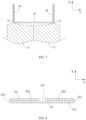
- the current collecting plate has a metal plate structure and is electrically conductive, and after the current collecting plate is bent to form a bending structure, as shown in FIG. 7 , the substrate 41 and the support plate 42 that are formed are approximately perpendicular.
- the bending structure is viewed at an angle shown in FIG. 7 , a surface of the substrate 41 is perpendicular to the traverse direction X, and the surface of the support plate 42 is approximately parallel to the traverse direction X.
- the bending structure is placed on a side of the body 11 of the electrode assembly 1 in the traverse direction X.
- the bending structure merely needs to include one support plate 42, and therefore, the bending structure is approximately L-shaped.
- the bending structure includes two support plates 42, and both the two support plates 42 extend from two ends of the substrate 41 in the longitudinal direction Y, and therefore, the bending structure is approximately U-shaped.
- the first tab 12 of the electrode assembly 1 protrudes from the body 11, and extends approximately in the transverse direction X, which is approximately the same as an extension direction of the support plate 42, and in this case, the first tab 12 may be attached to the support plate 42, with a relatively large attaching area between the first tab 12 and the support plate 42.
- first tab 12 and the support plate 42 may be connected in a manner such as laser welding.
- first tabs 12 of some electrode assemblies 1 are welded to one support plate 42, and first tabs 12 of some other electrode assemblies 1 are welded to the other support plate 42.
- the support plate 41 and the first tab 12 are bent, because the arc-shaped bending portion 421 is present at a bending position of the support plate 41, a contact area between the first tab 12 and the bending portion 421 is smooth and free of sharp corners, thereby reducing a probability of piercing the first tab 12; and in addition, the first tab 12 is bent along the arc-shaped surface of the bending portion 421, which can reduce stress concentration of the first tab 12 at the bending position, avoid splitting of the first tab 12, and ensure a current flow capacity of the first tab 12.
- the two support plates 42 are bent opposite to each other.
- the support plate 42 is bent until an end of the connecting portion 422 farther from the bending portion 421 abuts against the substrate 41.
- the first gap G1 between the connecting portion 422 and the substrate 41 is gradually narrowed in a direction extending away from the bending portion 421; and in other words, in the direction extending away from the bending portion 421, the connecting portion 422 is inclined towards the substrate, thereby increasing a curvature of the bending portion 421 and further increasing a contact area between the bending portion 421 and the first tab 12.
- the foregoing manufacturing method is a method for connecting the current collecting member 4 to the electrode assembly 1, and the manufacturing method may further include: forming the electrode assembly 1 and connecting the top cover assembly 3 to the current collecting member 4, to assemble the electrode assembly 1, the top cover assembly 3, and the current collecting member 4 together; and installing the electrode assembly 1 into the housing 2.
Description
- This application relates to the battery field, and in particular, to a secondary battery, and a method for manufacturing a secondary battery.
- A secondary battery generally includes an electrode assembly, a housing, electrode terminals, and a current collecting member, and the current collecting member is configured to electrically connect the electrode assembly to the electrode terminals. In a process of forming the secondary battery, usually, tabs of the electrode assembly are first welded to the current collecting member, and then the current collecting member and the tabs are bent, to reduce space occupied by the current collecting member and the tabs. However, a sharp corner is likely to form at a bending position of the current collecting member, and when the secondary battery vibrates, the sharp corner is likely to pierce the tabs, thereby reducing a current flow capacity of the tabs and affecting performance of the secondary battery.
-
EP2675000A1 provides a rechargeable battery including an electrode assembly, a case and a cap assembly. A positive electrode current collecting member includes a terminal connection portion that is fixed to the positive terminal, a side plate that is bent in the terminal connection portion, a connection plate that is bent at the side plate, and a support plate that is bent in the connection plate. -
JP2012221719A electric wire conductor 42 and are crimped thereto. -
CN108598353A provides a rechargeable battery including electrode assemblies, connecting members, a housing and a top cover. And first connecting plates are bent to an inner side of a guiding plate in a width direction after being welded to an electrode tab, and are parallel to an end surface of an electrode assembly body. - In view of the problem described in Background, a purpose of the present application is to provide a secondary battery, so as to prevent splitting of a tab and ensure a current flow capability of the tab.
- To achieve the foregoing objective, the present application provides a secondary battery according to
claim 1, where the secondary battery includes an electrode assembly, a housing, a top cover assembly, and a current collecting member. The electrode assembly is accommodated in the housing and includes a body and a first tab, and the first tab extends from an end of the body in a transverse direction. The top cover assembly includes a top cover plate and a first electrode terminal disposed on the top cover plate, and the top cover plate is connected to the housing. The current collecting member is connected to the first tab and the first electrode terminal. The current collecting member includes a substrate and a support plate, the substrate is disposed on a side of the body in the transverse direction and extends in a direction perpendicular to the transverse direction, and the support plate extends from an outer end of the substrate in the longitudinal direction and folds back to a side of the substrate farther from the body. The support plate includes a bending portion and a connecting portion, the bending portion is connected to the substrate and bent into an arc shape, and the connecting portion extends from an end of the bending portion farther from the substrate; and the first tab is connected to the connecting portion and bent along a surface of the bending portion. - A first gap is reserved between the connecting portion and the substrate. The first gap is gradually narrowed in a direction extending away from the bending portion. Further, preferably, an end of the connecting portion farther from the bending portion comes in contact with the substrate.
- There are two support plates, the two support plates respectively extend from both ends of the substrate in the longitudinal direction, and the two support plates are bent opposite to each other. In the longitudinal direction, a second gap is reserved between the connecting portions of the two support plates.
- The current collecting member further includes a terminal connecting plate, and the terminal connecting plate is perpendicular to the substrate and connected to the first electrode terminal and the substrate.
- A cross section of the bending portion is fan-shaped.
- The substrate and the support plate are integrally formed.
- The first tab includes a first part, a second part, and a third part, the first part extends from an end of the body in the transverse direction, the second part extends from an end of the first part farther from the body and is bent along the surface of the bending portion, and the third part extends from an end of the second part farther from the first part and is fastened to the connecting portion.
- The present application has the following beneficial effects: when the support plate and the first tab are bent, an arc-shaped bending portion is formed at a bending position of the support plate in this application; therefore, a contact area between the first tab and the bending portion is relatively smooth, and there is no sharp corner, thereby reducing a probability of piercing the first tab; and in addition, the first tab is bent along the arc-shaped surface of the bending portion, which can reduce stress concentration of the first tab at the bending position, avoid splitting of the first tab, and ensure a current flow capacity of the first tab.
-
-
FIG. 1 is a cross-sectional view of a secondary battery according to the present application. -
FIG. 2 is a cross-sectional view of a battery assembly of a secondary battery according to the present application. -
FIG. 3 is a schematic diagram of a first electrode plate according to the present application. -
FIG. 4 is an exploded view of a secondary battery according to the present application. -
FIG. 5 is another cross-sectional view of a secondary battery according to the present application. -
FIG. 6 is an enlarged view of a part in a dashed-line box ofFIG. 5 . -
FIG. 7 is a schematic diagram of a secondary battery in a forming process according to the present application. -
FIG. 8 is a cross-sectional view of a current collecting member of a secondary battery according to a non-inventive embodiment of the present application. -
FIG. 9 is a cross-sectional view of a current collecting member of a secondary battery according to another embodiment of the present application. - Herein, description of reference signs:
1. Electrode assembly 31. Top cover plate 11. Body 32. First electrode terminal 12. First tab 33. Second electrode terminal 121. First part 4. Current collecting member 122. Second part 41. Substrate 123. Third part 42. Support plate 13. Second tab 421. Bending portion 14. First electrode plate 422. Connecting portion 141. First coated area 43. Terminal connecting plate 142. First uncoated area G1. First gap 15. Second electrode plate G2. Second gap 16. Separator X. Traverse direction 2. Housing Y. Longitudinal direction 3. Top cover assembly Z. Height direction - The following clearly and completely describes the technical solutions in the embodiments of this application with reference to the accompanying drawings in the embodiments of this application; and apparently, the described embodiments are merely some but not all of the embodiments of this application. The following description of at least one example embodiment is actually only for a purpose of illustration, and shall not be considered as any limitation on this application and application or use thereof. All other embodiments obtained by a person of ordinary skill in the art based on the embodiments of this application without creative efforts shall fall within the protection scope of this application.
- In the description of this application, it should be understood that terms such as "first", "second", and "third" used to define components are only used for ease of distinguishing corresponding components; and unless otherwise specified, the foregoing terms have no special meanings, and therefore cannot be understood as a limitation on the protection scope of this application.
- The secondary battery in this application may be a lithium-ion battery.
- Referring to
FIG. 1 andFIG. 4 , a secondary battery includes anelectrode assembly 1, a housing 2, atop cover assembly 3, and a current collecting member 4. - Referring to
FIG. 2 , theelectrode assembly 1 includes afirst electrode plate 14, asecond electrode plate 15, and aseparator 16, and theseparator 16 is disposed between thefirst electrode plate 14 and thesecond electrode plate 15. Theelectrode assembly 1 is formed by spirally winding thefirst electrode plate 14, thesecond electrode plate 15, and theseparator 16, and an elliptical structure is formed by applying pressure. Theelectrode assembly 1 is a core component of the secondary battery for implementing charge and discharge functions. - The
first electrode plate 14 includes a first current collector and a first active material layer coating a surface of the first current collector. Thefirst electrode plate 14 may be a positive electrode plate, the first current collector is aluminum foil, and the first active material layer includes an active material such as lithium manganate or lithium-iron phosphate. The active material (such as lithium manganate or lithium-iron phosphate), a binder, a conductive agent, and a solvent may be made into a slurry, and then the slurry is applied onto two surfaces of the first current collector; and after the slurry becomes solidified, the first active material layer is formed. - Only some areas of the first current collector are coated with the first active material layer. Referring to
FIG. 3 , the first active material layer and the area of the first current collector that is coated with the first active material layer form a firstcoated area 141 of thefirst electrode plate 14, and an area of the first current collector that is not coated with the first active material layer forms a firstuncoated area 142 of thefirst electrode plate 14. There may be a plurality of firstuncoated areas 142, and the plurality of firstuncoated areas 142 may be arranged at intervals, and after thefirst electrode plate 14 is formed through winding, the plurality of firstuncoated areas 142 are stacked together. Thesecond electrode plate 15 includes a second current collector and a second active material layer coating a surface of the second current collector, the second active material layer and an area of the second current collector that is coated with the second active material layer form a second coated area of thesecond electrode plate 15, and an area of the second current collector that is not coated with the second active material layer forms a second uncoated area of thesecond electrode plate 15. There may be a plurality of second uncoated areas, and the plurality of second uncoated areas may be arranged at intervals, and after thesecond electrode plate 15 is formed through winding, the plurality of second uncoated areas are stacked together. A structure of thesecond electrode plate 15 is similar to a structure of thefirst electrode plate 14; and a difference lies in that a material of the second current collector may be copper foil, and the second active material layer includes an active material such as graphite or silicon. - The
separator 16 may be a polyethylene (PE) film, a polypropylene (PP) film, or a three-layer PP\PE\PP composite film. - After the
electrode assembly 1 is formed through winding, the firstcoated area 141 of thefirst electrode plate 14, theseparator 16, and the second coated area of thesecond electrode plate 15 form abody 11 of theelectrode assembly 1, the plurality of firstuncoated areas 142 of thefirst electrode plate 14 that are stacked together are used as afirst tab 12 of theelectrode assembly 1, and the plurality of second uncoated areas of thesecond electrode plate 15 that are stacked together are used as asecond tab 13 of theelectrode assembly 1. - A winding axis of the
electrode assembly 1 is parallel to the transverse direction X, thefirst tab 12 extends from an end of thebody 11 in the transverse direction X, and thesecond tab 13 extends from the other end of thebody 11 in the transverse direction X. Referring toFIG. 4 , the housing 2 may be in a hexahedral shape or another shape. An accommodating cavity is formed inside the housing 2, to accommodate theelectrode assembly 1 and an electrolyte. The housing 2 has an opening at an end, and theelectrode assembly 1 may be placed into the accommodating cavity of the housing 2 through the opening. The housing 2 may be made of a conductive metal material, and preferably, the housing 2 is made of aluminum or aluminum alloy with high reliability. - The
top cover assembly 3 includes atop cover plate 31, afirst electrode terminal 32, and asecond electrode terminal 33. Thetop cover plate 31 is disposed on the housing 2 and covers the opening of the housing 2, to seal theelectrode assembly 1 in the housing 2. Thetop cover plate 31 may be connected to the housing 2 through welding. Thefirst electrode terminal 32 and thesecond electrode terminal 33 are disposed on thetop cover plate 31, and thefirst electrode terminal 32 is electrically connected to thefirst tab 12, and thesecond electrode terminal 33 is electrically connected to thesecond tab 13. - The current collecting member 4 is connected to the
first tab 12 and thefirst electrode terminal 32. - Specifically, referring to
FIG. 4 to FIG. 6 , the current collecting member 4 includes asubstrate 41 and asupport plate 42, and thesubstrate 41 is disposed on a side of thebody 11 in the transverse direction X and extends in a direction perpendicular to the transverse direction X. Thesupport plate 42 extends from an outer end of thesubstrate 41 in the longitudinal direction Y and folds back to a side of thesubstrate 41 farther from thebody 11, and in the transverse direction X, thesupport plate 42 overlaps thesubstrate 41. - The
support plate 42 includes a bendingportion 421 and a connectingportion 422, the bendingportion 421 is connected to thesubstrate 41 and bent into an arc shape, and the connectingportion 422 extends from an end of the bendingportion 421 farther from thesubstrate 41. Thefirst tab 12 is connected to the connectingportion 422 and bent along a surface of the bendingportion 421. Preferably, thesubstrate 41 and thesupport plate 42 are integrally formed. - Referring to
FIG. 7 , to facilitate welding of thesupport plate 42 and thefirst tab 12, the current collecting member 4 is usually first bent into a U shape, and thesupport plate 42 is approximately perpendicular to thesubstrate 41 at that time; and after the welding of thesupport plate 42 and thefirst tab 12 is completed, thesupport plate 42 and thefirst tab 12 are then bent, to reduce space occupied by thesupport plate 42 in the transverse direction X. - When the
support plate 42 and thefirst tab 12 are bent, an arc-shapedbending portion 421 is formed at a bending position of thesupport plate 42 in this application, and therefore, a contact area between thefirst tab 12 and the bendingportion 421 is relatively smooth and free of sharp corners, thereby reducing a probability of piercing thefirst tab 12. In addition, thefirst tab 12 is bent along the arc-shaped surface of the bendingportion 421, which can reduce stress concentration of thefirst tab 12 at the bending position, avoid splitting of thefirst tab 12, and ensure a current flow capacity of thefirst tab 12. - Referring to
FIG. 1 , the current collecting member 4 further includes aterminal connecting plate 43, and theterminal connecting plate 43 is perpendicular to thesubstrate 41 and connected to thefirst electrode terminal 32 and thesubstrate 41. Theterminal connecting plate 43 may be connected to thefirst electrode terminal 32 through welding. Thesubstrate 41 may be bent downward from an end of theterminal connecting plate 43 in the transverse direction X. Thesubstrate 41, thesupport plate 42, and theterminal connecting plate 43 may be integrally formed. - Referring to
FIG. 6 , thefirst tab 12 includes afirst part 121, asecond part 122, and athird part 123, thefirst part 121 extends from an end of thebody 11 in the transverse direction X, thesecond part 122 extends from an end of thefirst part 121 farther from thebody 11 and is bent along the surface of the bendingportion 421, and thethird part 123 extends from an end of thesecond part 122 farther from thefirst part 121 and is fastened to the connectingportion 422. - The
first tab 12 is formed by a plurality of firstuncoated areas 142 that are stacked, and each of the firstuncoated areas 142 is metal foil with a relatively small thickness. In thethird part 123, the plurality of firstuncoated areas 142 are fastened to the connectingportion 422 through ultrasonic welding. In thesecond part 122, the plurality of firstuncoated areas 142 are bent along the bendingportion 421; and if a sharp corner is formed at the bendingportion 421, the firstuncoated area 142 close to the bendingportion 421 is likely to be pierced; and however, in this application, the bendingportion 421 is arc-shaped, force between the bendingportion 421 and the firstuncoated area 142 is more even, and therefore, the firstuncoated area 142 close to the bendingportion 421 is unlikely to be pierced. - Referring to
FIG. 8 andFIG. 9 , a cross section of the bendingportion 421 is fan-shaped, and a surface of the bendingportion 421 that is in contact with thesecond part 122 is an arc surface. With the arc surface, force between the bendingportion 421 and thesecond part 122 is more even, to reduce stress concentration. - A first gap G1 is reserved between the connecting
portion 422 and thesubstrate 41. Disposing the first gap G1 can increase a diameter of the bendingportion 421, thereby improving a stress release effect and avoiding splitting of thefirst tab 12. - Referring to
FIG. 9 , the first gap G1 is gradually narrowed in a direction extending away from the bendingportion 421, and in other words, the connectingportion 422 is inclined towards thesubstrate 41. When the connectingportion 422 is inclined, a curvature of the bendingportion 421 may be increased (referring toFIG. 8 , when the connectingportion 422 is parallel to thesubstrate 41, a central angle of the bendingportion 421 is equal to 180 degrees; and referring toFIG. 9 , when the connectingportion 422 is inclined, a central angle of the bendingportion 421 is greater than 180 degrees), and a contact area between the bendingportion 421 and thefirst tab 12 is increased, thereby dispersing stress more effectively and avoiding stress concentration. - In the secondary battery, to avoid contact between the
electrode assembly 1 and the housing 2 and prevent a short circuit, an insulation plate is usually disposed between theelectrode assembly 1 and the housing 2. In a forming process of the secondary battery, usually, theelectrode assembly 1, thetop cover assembly 3, and the current collecting member 4 are first assembled together, and then theelectrode assembly 1 is installed into the housing 2; and in the process of installing theelectrode assembly 1 into the housing, the current collecting member 4 and thefirst tab 12 are likely to be in contact with the insulation plate. If the connectingportion 422 is parallel to thesubstrate 41, in the process of installing theelectrode assembly 1 into the housing, a free end (with a sharp corner) of thefirst tab 12 is likely to be in contact with the insulation plate, to damage the insulation plate and affect safety performance of the secondary battery. In addition, if the connectingportion 422 is inclined towards thesubstrate 41, in the process of installing theelectrode assembly 1 into the housing, thesecond part 122 of thefirst tab 12 is likely to be in contact with the insulation plate; and however, because thesecond part 122 is integrally bent into an arc shape and a surface is relatively smooth, the insulation plate is unlikely to be damaged, thereby improving the safety performance of the secondary battery. - Further, an end of the connecting
portion 422 farther from the bendingportion 421 comes in contact with thesubstrate 41, so that the curvature of the bendingportion 421 can be maximized to avoid stress concentration. - To increase a capacity of the secondary battery, a plurality of
electrode assemblies 1 are usually disposed and arranged in the longitudinal direction Y There are twosupport plates 42, the twosupport plates 42 respectively extend from both ends of thesubstrate 41 in the longitudinal direction Y, and the twosupport plates 42 are bent opposite to each other.First tabs 12 of someelectrode assemblies 1 may be welded to onesupport plate 42, andfirst tabs 12 of remainingelectrode assemblies 1 may be welded to theother support plate 42. - In the longitudinal direction Y, a second gap G2 is reserved between the connecting
portions 422 of the twosupport plates 42. Reserving the second gap G2 between the twosupport plates 42 can avoid overlapping of the twosupport plates 42 during bending, and prevent thesupport plates 42 from occupying excessive space in the transverse direction X. - In addition, the secondary battery in the foregoing embodiments can be manufactured by using the manufacturing method of claim 7: S1: Bend a current collecting plate to form a bending structure, where the bending structure includes a
substrate 41 and asupport plate 42 that are bent toward each other, and thesupport plate 42 extends from an outer end of thesubstrate 41 in the longitudinal direction Y; - In this step, the current collecting plate has a metal plate structure and is electrically conductive, and after the current collecting plate is bent to form a bending structure, as shown in
FIG. 7 , thesubstrate 41 and thesupport plate 42 that are formed are approximately perpendicular. In addition, when the bending structure is viewed at an angle shown inFIG. 7 , a surface of thesubstrate 41 is perpendicular to the traverse direction X, and the surface of thesupport plate 42 is approximately parallel to the traverse direction X. During manufacturing of the secondary battery, the bending structure is placed on a side of thebody 11 of theelectrode assembly 1 in the traverse direction X. - When the secondary battery includes one
electrode assembly 1, the bending structure merely needs to include onesupport plate 42, and therefore, the bending structure is approximately L-shaped. When the secondary battery includes a plurality ofelectrode assemblies 1 that are arranged in the longitudinal direction Y, the bending structure includes twosupport plates 42, and both the twosupport plates 42 extend from two ends of thesubstrate 41 in the longitudinal direction Y, and therefore, the bending structure is approximately U-shaped. - S2: Connect the
first tab 12 to thesupport plate 42. - As shown in
FIG. 7 , in theelectrode assembly 1, thefirst tab 12 of theelectrode assembly 1 protrudes from thebody 11, and extends approximately in the transverse direction X, which is approximately the same as an extension direction of thesupport plate 42, and in this case, thefirst tab 12 may be attached to thesupport plate 42, with a relatively large attaching area between thefirst tab 12 and thesupport plate 42. - In this step, the
first tab 12 and thesupport plate 42 may be connected in a manner such as laser welding. In addition, when the secondary battery includes a plurality ofelectrode assemblies 1,first tabs 12 of someelectrode assemblies 1 are welded to onesupport plate 42, andfirst tabs 12 of someother electrode assemblies 1 are welded to theother support plate 42. - S3: Bend the
first tab 12 and thesupport plate 42 that are connected, so that thesupport plate 42 folds back to a side of thesubstrate 41 in the transverse direction X, where after being bent, thesupport plate 42 includes an arc-shapedbending portion 421 and the connectingportion 422, the bendingportion 421 is connected to thesubstrate 41, and the connectingportion 422 extends from an end of the bendingportion 421 farther from thesubstrate 41, to form the current collecting member 4. - In the foregoing steps, after the
first tab 12 is connected to thesupport plate 42, functions of thefirst tab 12 and thefirst electrode terminal 32 can be implemented by using the bending structure; however, in this case, thefirst tab 12 and thesupport plate 42 extend in the transverse direction X; and to reduce space occupied by the secondary battery in the transverse direction X, thefirst tab 12 and thesupport plate 42 are bent again, so that thesupport plate 42 is close to thesubstrate 41. - In addition, when the
support plate 41 and thefirst tab 12 are bent, because the arc-shapedbending portion 421 is present at a bending position of thesupport plate 41, a contact area between thefirst tab 12 and the bendingportion 421 is smooth and free of sharp corners, thereby reducing a probability of piercing thefirst tab 12; and in addition, thefirst tab 12 is bent along the arc-shaped surface of the bendingportion 421, which can reduce stress concentration of thefirst tab 12 at the bending position, avoid splitting of thefirst tab 12, and ensure a current flow capacity of thefirst tab 12. - In this step, when the secondary battery includes a plurality of
electrode assemblies 1, the twosupport plates 42 are bent opposite to each other. - Specifically, in the foregoing step S3, during bending of the
first tab 12 and thesupport plate 42, thesupport plate 42 is bent until an end of the connectingportion 422 farther from the bendingportion 421 abuts against thesubstrate 41. - In this embodiment, when the end of the connecting
portion 422 farther from the bendingportion 421 abuts against thesubstrate 41, as shown inFIG. 9 , the first gap G1 between the connectingportion 422 and thesubstrate 41 is gradually narrowed in a direction extending away from the bendingportion 421; and in other words, in the direction extending away from the bendingportion 421, the connectingportion 422 is inclined towards the substrate, thereby increasing a curvature of the bendingportion 421 and further increasing a contact area between the bendingportion 421 and thefirst tab 12. - It should be noted that the foregoing manufacturing method is a method for connecting the current collecting member 4 to the
electrode assembly 1, and the manufacturing method may further include: forming theelectrode assembly 1 and connecting thetop cover assembly 3 to the current collecting member 4, to assemble theelectrode assembly 1, thetop cover assembly 3, and the current collecting member 4 together; and installing theelectrode assembly 1 into the housing 2.
Claims (8)
- A secondary battery, comprising an electrode assembly (1), a housing (2), a top cover assembly (3), and a current collecting member (4), characterized in thatthe electrode assembly (1) is accommodated in the housing (2) and comprises a body (11) and a first tab (12), and the first tab (12) extends from an end of the body (11) in a transverse direction (X);the top cover assembly (3) comprises a top cover plate (31) and a first electrode terminal (32) disposed on the top cover plate (31), the top cover plate (31) is connected to the housing (2), and the current collecting member (4) is connected to the first tab (12) and the first electrode terminal (32);the current collecting member (4) comprises a substrate (41) and a support plate (42), the substrate (41) extends in a direction perpendicular to a transverse direction (X), and the support plate (42) extends from an outer end of the substrate (41) in a longitudinal direction (Y) and folds back to a side of the substrate (41) in the transverse direction (X); andthe support plate (42) comprises a bending portion (421) and a connecting portion (422), the bending portion (421) is connected to the substrate (41) and bent into an arc shape, and the connecting portion (422) extends from an end of the bending portion (421) farther from the substrate (41);the substrate (41) is disposed on a side of the body (11) in the transverse direction (X), and the support plate (42) folds back to a side of the substrate (41) farther from the body (11); the first tab (12) is connected to the connecting portion (422) and bent along a surface of the bending portion (421);the first tab (12) comprises a first part (121), a second part (122), and a third part (123), the first part (121) extends from an end of the body (11) in the transverse direction (X), the second part (122) extends from an end of the first part (121) farther from the body (11) and is bent along the surface of the bending portion (421), and the third part (123) extends from an end of the second part (122) farther from the first part (121) and is fastened to the connecting portion (422);a cross section of the bending portion (421) is fan-shaped, and a surface of the bending portion (421) that is in contact with the second part (122) is an arc surface;a first gap (G1) is reserved between the connecting portion (422) and the substrate (41);a first gap (G1) is gradually narrowed in a direction extending away from the bending portion (421).
- The secondary battery according to claim 1, characterized in that an end of the connecting portion (422) farther from the bending portion (421) comes in contact with the substrate (41).
- The secondary battery according to claim 1 or 2, characterized in that there are two support plates (42), the two support plates (42) respectively extend from both ends of the substrate (41) in the longitudinal direction (Y), and the two support plates (42) are bent opposite to each other.
- The secondary battery according to claim 3, characterized in that a second gap (G2) is reserved between connecting portions (422) of the two support plates (42) in the longitudinal direction (Y).
- The secondary battery according to any of claims 1 to 4, characterized in that the current collecting member (4) further comprises a terminal connecting plate (43), and the terminal connecting plate (43) is perpendicular to the substrate (41) and connected to the substrate (41).
- The secondary battery according to any of claims 1 to 5, characterized in that the substrate (41) and the support plate (42) are integrally formed.
- A method for manufacturing the secondary battery according to any one of claims 1-6, characterized in that the secondary battery comprises an electrode assembly (1) and a current collecting member (4), the electrode assembly (1) comprises a body (11) and a first tab (12), and the first tab (12) extends from an end of the body (11) in a transverse direction (X); and
the manufacturing method comprises:bending a current collecting plate to form a bending structure, wherein the bending structure comprises a substrate (41) and a support plate (42) that are bent toward each other, and the support plate (42) extends from an outer end of the substrate (41) in a longitudinal direction (Y);connecting the first tab (12) to the support plate (42); andbending the first tab (12) and the support plate (42) that are connected, wherein during bending, a bending portion (421) and a connecting portion (422) are formed in the support plate (42), the bending portion (421) is located at a bending position of the support plate (42) and is arc-shaped, the connecting portion (422) extends from an end of the bending portion (421) farther from the substrate (41), and the substrate (41), the bending portion (421), and the connecting portion (422) form the current collecting member (4). - The method for manufacturing a secondary battery according to claim 7, characterized in that during bending of the first tab (12) and the support plate (42) that are connected, the manufacturing method further comprises:
bending the first tab (12) and the support plate (42) that are connected, until an end of the connecting portion (422) farther from the bending portion (421) abuts against the substrate (41).
Applications Claiming Priority (2)
| Application Number | Priority Date | Filing Date | Title |
|---|---|---|---|
| CN201821752622.XU CN208819970U (en) | 2018-10-26 | 2018-10-26 | Secondary cell |
| PCT/CN2019/112513 WO2020083278A1 (en) | 2018-10-26 | 2019-10-22 | Current collecting member, secondary battery, and manufacturing method for secondary battery |
Publications (4)
| Publication Number | Publication Date |
|---|---|
| EP3852165A1 EP3852165A1 (en) | 2021-07-21 |
| EP3852165A4 EP3852165A4 (en) | 2021-12-15 |
| EP3852165B1 true EP3852165B1 (en) | 2024-02-21 |
| EP3852165C0 EP3852165C0 (en) | 2024-02-21 |
Family
ID=66280253
Family Applications (1)
| Application Number | Title | Priority Date | Filing Date |
|---|---|---|---|
| EP19874930.1A Active EP3852165B1 (en) | 2018-10-26 | 2019-10-22 | Secondary battery and manufacturing method for secondary battery |
Country Status (4)
| Country | Link |
|---|---|
| US (1) | US20210234175A1 (en) |
| EP (1) | EP3852165B1 (en) |
| CN (1) | CN208819970U (en) |
| WO (1) | WO2020083278A1 (en) |
Families Citing this family (9)
| Publication number | Priority date | Publication date | Assignee | Title |
|---|---|---|---|---|
| CN208819970U (en) * | 2018-10-26 | 2019-05-03 | 宁德时代新能源科技股份有限公司 | Secondary cell |
| CN209675429U (en) * | 2019-05-21 | 2019-11-22 | 宁德时代新能源科技股份有限公司 | A kind of secondary cell |
| CN209786061U (en) * | 2019-07-01 | 2019-12-13 | 宁德时代新能源科技股份有限公司 | Secondary battery |
| CN110350112A (en) * | 2019-07-23 | 2019-10-18 | 宁德时代新能源科技股份有限公司 | Secondary battery |
| CN210136894U (en) * | 2019-08-13 | 2020-03-10 | 宁德时代新能源科技股份有限公司 | Secondary battery |
| JPWO2021186947A1 (en) * | 2020-03-17 | 2021-09-23 | ||
| CN111446408A (en) | 2020-05-14 | 2020-07-24 | 中航锂电(洛阳)有限公司 | Battery core, battery and battery manufacturing method |
| CN115458872B (en) * | 2022-11-10 | 2023-03-31 | 瑞浦兰钧能源股份有限公司 | Adapter sheet of secondary battery |
| CN115000642A (en) * | 2022-06-10 | 2022-09-02 | 宁夏宝丰昱能科技有限公司 | Square laminated battery |
Family Cites Families (5)
| Publication number | Priority date | Publication date | Assignee | Title |
|---|---|---|---|---|
| JP2012221719A (en) * | 2011-04-08 | 2012-11-12 | Asuka Business Corporation Kk | Crimp terminal |
| US9287550B2 (en) * | 2012-06-11 | 2016-03-15 | Samsung Sdi Co., Ltd. | Rechargeable battery |
| CN108258180B (en) * | 2018-01-16 | 2020-09-29 | 宁德时代新能源科技股份有限公司 | Current collecting member and battery |
| CN108598353B (en) * | 2018-01-16 | 2020-10-23 | 宁德时代新能源科技股份有限公司 | Rechargeable battery |
| CN208819970U (en) * | 2018-10-26 | 2019-05-03 | 宁德时代新能源科技股份有限公司 | Secondary cell |
-
2018
- 2018-10-26 CN CN201821752622.XU patent/CN208819970U/en active Active
-
2019
- 2019-10-22 EP EP19874930.1A patent/EP3852165B1/en active Active
- 2019-10-22 WO PCT/CN2019/112513 patent/WO2020083278A1/en unknown
-
2021
- 2021-04-14 US US17/230,988 patent/US20210234175A1/en active Pending
Also Published As
| Publication number | Publication date |
|---|---|
| EP3852165A4 (en) | 2021-12-15 |
| EP3852165A1 (en) | 2021-07-21 |
| US20210234175A1 (en) | 2021-07-29 |
| CN208819970U (en) | 2019-05-03 |
| WO2020083278A1 (en) | 2020-04-30 |
| EP3852165C0 (en) | 2024-02-21 |
Similar Documents
| Publication | Publication Date | Title |
|---|---|---|
| EP3852165B1 (en) | Secondary battery and manufacturing method for secondary battery | |
| US8628876B2 (en) | Electrode assembly and lithium secondary battery with same | |
| US10333113B2 (en) | Rechargeable battery having retainer | |
| EP2388847B1 (en) | Secondary battery comprising first and second collector plates that are enmeshed together | |
| US9793569B2 (en) | Electric storage element | |
| EP2472642B1 (en) | Rechargeable battery | |
| KR20050121907A (en) | Secondary battery and electrodes assembly using the same | |
| US10256457B2 (en) | Secondary battery | |
| US20160293928A1 (en) | Prismatic secondary battery | |
| US20120028091A1 (en) | Secondary battery | |
| US20110151318A1 (en) | Secondary battery | |
| EP3067958B1 (en) | Electrode assembly and secondary battery having the electrode assembly | |
| EP2736102B1 (en) | Electrode assembly and rechargeable battery having the same | |
| EP2560230A1 (en) | Secondary battery with improved safety | |
| JP4451654B2 (en) | Lithium secondary battery | |
| US20140212715A1 (en) | Rechargeable battery | |
| US8043737B2 (en) | Secondary battery and method with electrode tap positioned at short side portion of secondary battery can | |
| US11043689B2 (en) | Electrode assembly, and rechargeable battery comprising same | |
| CN106328843B (en) | Secondary battery | |
| EP3703160B1 (en) | Secondary battery | |
| US20220115751A1 (en) | Secondary battery | |
| US20220407154A1 (en) | Power storage device | |
| EP4340099A1 (en) | Cylindrical secondary battery | |
| EP4220795A2 (en) | Cylindrical secondary battery | |
| EP4164051A1 (en) | Secondary battery |
Legal Events
| Date | Code | Title | Description |
|---|---|---|---|
| STAA | Information on the status of an ep patent application or granted ep patent |
Free format text: STATUS: THE INTERNATIONAL PUBLICATION HAS BEEN MADE |
|
| PUAI | Public reference made under article 153(3) epc to a published international application that has entered the european phase |
Free format text: ORIGINAL CODE: 0009012 |
|
| STAA | Information on the status of an ep patent application or granted ep patent |
Free format text: STATUS: REQUEST FOR EXAMINATION WAS MADE |
|
| 17P | Request for examination filed |
Effective date: 20210414 |
|
| AK | Designated contracting states |
Kind code of ref document: A1 Designated state(s): AL AT BE BG CH CY CZ DE DK EE ES FI FR GB GR HR HU IE IS IT LI LT LU LV MC MK MT NL NO PL PT RO RS SE SI SK SM TR |
|
| A4 | Supplementary search report drawn up and despatched |
Effective date: 20211115 |
|
| RIC1 | Information provided on ipc code assigned before grant |
Ipc: H01M 50/296 20210101ALI20211109BHEP Ipc: H01M 50/103 20210101ALI20211109BHEP Ipc: H01M 10/052 20100101ALI20211109BHEP Ipc: H01M 10/04 20060101ALI20211109BHEP Ipc: H01M 4/78 20060101AFI20211109BHEP |
|
| DAV | Request for validation of the european patent (deleted) | ||
| DAX | Request for extension of the european patent (deleted) | ||
| STAA | Information on the status of an ep patent application or granted ep patent |
Free format text: STATUS: EXAMINATION IS IN PROGRESS |
|
| 17Q | First examination report despatched |
Effective date: 20220608 |
|
| REG | Reference to a national code |
Ref document number: 602019047089 Country of ref document: DE Ref country code: DE Ref legal event code: R079 Free format text: PREVIOUS MAIN CLASS: H01M0002200000 Ipc: H01M0010040000 |
|
| RIC1 | Information provided on ipc code assigned before grant |
Ipc: H01M 4/78 20060101ALI20231020BHEP Ipc: H01M 50/536 20210101ALI20231020BHEP Ipc: H01M 50/533 20210101ALI20231020BHEP Ipc: H01M 50/50 20210101ALI20231020BHEP Ipc: H01M 50/296 20210101ALI20231020BHEP Ipc: H01M 50/103 20210101ALI20231020BHEP Ipc: H01M 10/052 20100101ALI20231020BHEP Ipc: H01M 10/04 20060101AFI20231020BHEP |
|
| GRAP | Despatch of communication of intention to grant a patent |
Free format text: ORIGINAL CODE: EPIDOSNIGR1 |
|
| STAA | Information on the status of an ep patent application or granted ep patent |
Free format text: STATUS: GRANT OF PATENT IS INTENDED |
|
| INTG | Intention to grant announced |
Effective date: 20231201 |
|
| GRAS | Grant fee paid |
Free format text: ORIGINAL CODE: EPIDOSNIGR3 |
|
| GRAA | (expected) grant |
Free format text: ORIGINAL CODE: 0009210 |
|
| STAA | Information on the status of an ep patent application or granted ep patent |
Free format text: STATUS: THE PATENT HAS BEEN GRANTED |
|
| RAP3 | Party data changed (applicant data changed or rights of an application transferred) |
Owner name: CONTEMPORARY AMPEREX TECHNOLOGY CO., LIMITED |
|
| AK | Designated contracting states |
Kind code of ref document: B1 Designated state(s): AL AT BE BG CH CY CZ DE DK EE ES FI FR GB GR HR HU IE IS IT LI LT LU LV MC MK MT NL NO PL PT RO RS SE SI SK SM TR |
|
| REG | Reference to a national code |
Ref country code: GB Ref legal event code: FG4D |
|
| REG | Reference to a national code |
Ref country code: CH Ref legal event code: EP |
|
| REG | Reference to a national code |
Ref country code: IE Ref legal event code: FG4D |
|
| REG | Reference to a national code |
Ref country code: DE Ref legal event code: R096 Ref document number: 602019047089 Country of ref document: DE |