EP4030537B1 - Secondary battery and manufacturing method therefor, battery module, and apparatus - Google Patents
Secondary battery and manufacturing method therefor, battery module, and apparatus Download PDFInfo
- Publication number
- EP4030537B1 EP4030537B1 EP20935156.8A EP20935156A EP4030537B1 EP 4030537 B1 EP4030537 B1 EP 4030537B1 EP 20935156 A EP20935156 A EP 20935156A EP 4030537 B1 EP4030537 B1 EP 4030537B1
- Authority
- EP
- European Patent Office
- Prior art keywords
- tab
- transition connecting
- current collecting
- guiding section
- connecting piece
- Prior art date
- Legal status (The legal status is an assumption and is not a legal conclusion. Google has not performed a legal analysis and makes no representation as to the accuracy of the status listed.)
- Active
Links
- 238000004519 manufacturing process Methods 0.000 title description 6
- 230000007704 transition Effects 0.000 claims description 101
- 230000000712 assembly Effects 0.000 claims description 8
- 238000000429 assembly Methods 0.000 claims description 8
- 239000002356 single layer Substances 0.000 claims description 2
- 238000003466 welding Methods 0.000 description 32
- 238000010586 diagram Methods 0.000 description 12
- 238000000034 method Methods 0.000 description 10
- 230000009286 beneficial effect Effects 0.000 description 9
- 239000010410 layer Substances 0.000 description 7
- 239000011149 active material Substances 0.000 description 4
- 238000005452 bending Methods 0.000 description 4
- 239000002360 explosive Substances 0.000 description 3
- 238000004804 winding Methods 0.000 description 3
- 230000002452 interceptive effect Effects 0.000 description 2
- 229910000838 Al alloy Inorganic materials 0.000 description 1
- 229910052782 aluminium Inorganic materials 0.000 description 1
- XAGFODPZIPBFFR-UHFFFAOYSA-N aluminium Chemical compound [Al] XAGFODPZIPBFFR-UHFFFAOYSA-N 0.000 description 1
- 230000005540 biological transmission Effects 0.000 description 1
- 230000000694 effects Effects 0.000 description 1
- 239000003792 electrolyte Substances 0.000 description 1
- 238000004146 energy storage Methods 0.000 description 1
- 230000007613 environmental effect Effects 0.000 description 1
- 239000011888 foil Substances 0.000 description 1
- 239000000446 fuel Substances 0.000 description 1
- 238000003754 machining Methods 0.000 description 1
- 239000000463 material Substances 0.000 description 1
- 229910052751 metal Inorganic materials 0.000 description 1
- 239000002184 metal Substances 0.000 description 1
- 230000000149 penetrating effect Effects 0.000 description 1
- 238000006748 scratching Methods 0.000 description 1
- 230000002393 scratching effect Effects 0.000 description 1
- 238000000926 separation method Methods 0.000 description 1
Images


Classifications
-
- H—ELECTRICITY
- H01—ELECTRIC ELEMENTS
- H01M—PROCESSES OR MEANS, e.g. BATTERIES, FOR THE DIRECT CONVERSION OF CHEMICAL ENERGY INTO ELECTRICAL ENERGY
- H01M4/00—Electrodes
- H01M4/02—Electrodes composed of, or comprising, active material
- H01M4/64—Carriers or collectors
- H01M4/70—Carriers or collectors characterised by shape or form
- H01M4/78—Shapes other than plane or cylindrical, e.g. helical
-
- H—ELECTRICITY
- H01—ELECTRIC ELEMENTS
- H01M—PROCESSES OR MEANS, e.g. BATTERIES, FOR THE DIRECT CONVERSION OF CHEMICAL ENERGY INTO ELECTRICAL ENERGY
- H01M50/00—Constructional details or processes of manufacture of the non-active parts of electrochemical cells other than fuel cells, e.g. hybrid cells
- H01M50/50—Current conducting connections for cells or batteries
- H01M50/531—Electrode connections inside a battery casing
- H01M50/533—Electrode connections inside a battery casing characterised by the shape of the leads or tabs
-
- H—ELECTRICITY
- H01—ELECTRIC ELEMENTS
- H01M—PROCESSES OR MEANS, e.g. BATTERIES, FOR THE DIRECT CONVERSION OF CHEMICAL ENERGY INTO ELECTRICAL ENERGY
- H01M10/00—Secondary cells; Manufacture thereof
- H01M10/04—Construction or manufacture in general
- H01M10/049—Processes for forming or storing electrodes in the battery container
-
- H—ELECTRICITY
- H01—ELECTRIC ELEMENTS
- H01M—PROCESSES OR MEANS, e.g. BATTERIES, FOR THE DIRECT CONVERSION OF CHEMICAL ENERGY INTO ELECTRICAL ENERGY
- H01M50/00—Constructional details or processes of manufacture of the non-active parts of electrochemical cells other than fuel cells, e.g. hybrid cells
- H01M50/10—Primary casings, jackets or wrappings of a single cell or a single battery
- H01M50/102—Primary casings, jackets or wrappings of a single cell or a single battery characterised by their shape or physical structure
- H01M50/103—Primary casings, jackets or wrappings of a single cell or a single battery characterised by their shape or physical structure prismatic or rectangular
-
- H—ELECTRICITY
- H01—ELECTRIC ELEMENTS
- H01M—PROCESSES OR MEANS, e.g. BATTERIES, FOR THE DIRECT CONVERSION OF CHEMICAL ENERGY INTO ELECTRICAL ENERGY
- H01M50/00—Constructional details or processes of manufacture of the non-active parts of electrochemical cells other than fuel cells, e.g. hybrid cells
- H01M50/50—Current conducting connections for cells or batteries
- H01M50/531—Electrode connections inside a battery casing
- H01M50/536—Electrode connections inside a battery casing characterised by the method of fixing the leads to the electrodes, e.g. by welding
-
- H—ELECTRICITY
- H01—ELECTRIC ELEMENTS
- H01M—PROCESSES OR MEANS, e.g. BATTERIES, FOR THE DIRECT CONVERSION OF CHEMICAL ENERGY INTO ELECTRICAL ENERGY
- H01M2220/00—Batteries for particular applications
- H01M2220/20—Batteries in motive systems, e.g. vehicle, ship, plane
-
- Y—GENERAL TAGGING OF NEW TECHNOLOGICAL DEVELOPMENTS; GENERAL TAGGING OF CROSS-SECTIONAL TECHNOLOGIES SPANNING OVER SEVERAL SECTIONS OF THE IPC; TECHNICAL SUBJECTS COVERED BY FORMER USPC CROSS-REFERENCE ART COLLECTIONS [XRACs] AND DIGESTS
- Y02—TECHNOLOGIES OR APPLICATIONS FOR MITIGATION OR ADAPTATION AGAINST CLIMATE CHANGE
- Y02E—REDUCTION OF GREENHOUSE GAS [GHG] EMISSIONS, RELATED TO ENERGY GENERATION, TRANSMISSION OR DISTRIBUTION
- Y02E60/00—Enabling technologies; Technologies with a potential or indirect contribution to GHG emissions mitigation
- Y02E60/10—Energy storage using batteries
Definitions
- the present disclosure relates to a technical field of batteries, and particularly relates to a secondary battery and manufacturing method thereof, a battery module and an apparatus.
- Secondary batteries have advantages of high energy density, long service life, energy saving and environmental protection, etc., and are widely used in different fields such as alternative fuel vehicles and energy storage power stations.
- a secondary battery includes an electrode assembly and a current collecting member.
- the electrode assembly includes a main body portion and tabs extending from the main body portion.
- the tabs and the current collecting member are usually connected, forming a connection region between them.
- the secondary battery is charged and discharged many times, and it is found that the connection region between the tab and the current collecting member has a poor current flowing capability, which affects the performance of the secondary battery.
- US2019221825A1 relates to a secondary battery, which includes: an electrode assembly including a main tab; a current collecting member adjacent the main tab; and a sub-tab electrically connecting the main tab to the current collecting member.
- the main tab is in and welded to the sub-tab, and the sub-tab and the main tab are bent in the same direction on the current collecting member.
- EP3451417A1 relates to a secondary battery capable of achieving a higher capacity than a related art jelly-rolled electrode assembly
- the secondary battery includes: an electrode assembly including a first electrode plate and a second electrode plate, each having an uncoated portion protruding from a respective one of laterally opposite sides of the electrode assembly; a current collector at a region corresponding to the uncoated portion of the electrode assembly; and a ductile sub-tab electrically connecting the uncoated portion of the electrode assembly to the current collector, wherein the uncoated portion and the sub-tab are connected to each other and bent together in the same direction.
- the embodiment of the present application provides a secondary battery and manufacturing method thereof, a battery module and an apparatus, which can reduce the possibility of decrease of the current flowing capability of the tab.
- the embodiment of the present application provides a secondary battery, including:
- the present application provides a manufacturing method for a secondary battery, the method includes steps of:
- the present application provides a battery module, including the secondary battery according to the above-mentioned embodiments.
- the present application provides an apparatus using a secondary battery as a power source, wherein the apparatus includes the secondary battery above-mentioned.
- the tab of the electrode assembly and the current collecting portion of the transition connecting piece are connected to form a first connection region, and the fixing portion of the transition connecting piece and the guiding section of the current collecting member are connected to form a second connection region; when achieving the connection of the tab with the guiding section, the first connection region and the second connection region will not overlap, thereby improving the current flowing capability of the tab.
- the embodiment of the present application provides an apparatus that uses a secondary battery 30 as a power source.
- the apparatus may be but is not limited to, a vehicle, a ship, or an aircraft.
- an embodiment of the present application provides a vehicle 1 including a vehicle body and a battery block.
- the battery block is provided on the vehicle body.
- the vehicle 1 may be a pure electric vehicle, a hybrid electric vehicle or an extended-range vehicle.
- the vehicle body is provided with a drive motor electrically connected to the battery block.
- the battery block provides power to the drive motor.
- the drive motor is connected to wheels on the vehicle body through a transmission mechanism to drive the vehicle to travel.
- the battery block may be horizontally arranged at the bottom of the vehicle body.
- the battery block may be formed as a battery pack 10.
- the battery pack 10 may be provided in various manners.
- the battery pack 10 includes a housing and a battery module 20 disposed in the housing. There may be one or more battery modules 20. The one or more battery modules 20 are arranged in a row in the housing.
- the type of the housing is not limited.
- the housing may be a frame-shaped housing, a disc-shaped housing, or a box-shaped housing.
- the housing includes a lower housing for receiving the battery module 20 and an upper housing for closing the lower housing. After closing the lower housing, the upper housing together with the lower housing forms an accommodating portion for accommodating the battery module 20.
- the battery pack 10 includes a housing and a plurality of secondary batteries 30 directly arranged in the housing.
- the battery block may also be formed as a battery module 20, and a plurality of battery modules 20 are arranged in a housing and installed on the vehicle body.
- the battery module 20 includes a plurality of secondary batteries 30.
- the battery module 20 may be provided in various manners.
- the battery module 20 includes an accommodating portion and a plurality of secondary batteries 30 located in the accommodating portion.
- the plurality of secondary batteries 30 are arranged side by side in the accommodating portion.
- the accommodating portion may be provided in various manners, and for example, the accommodating portion includes a shell and a cover plate covering the shell; or, the accommodating portion includes side plates and end plates that are connected one after another and define an enclosure; or, the accommodating portion includes two ends plates arranged oppositely and a strap band surrounding the end plates and the secondary batteries 30.
- the secondary battery 30 includes a casing 31, an electrode assembly 32 disposed in the casing 31, and a cap assembly 40 hermetically connected with the casing 31.
- the casing 31 according to the embodiment of the present application is formed in a cubic shape or other shapes.
- the casing 31 includes an internal space for accommodating the electrode assembly 32 and electrolyte, and an opening communicating with the internal space.
- the casing 31 may be made of materials such as aluminum, aluminum alloy, plastic or other else.
- the electrode assembly 32 can be formed by stacking or winding a first electrode plate, a second electrode plate, and a separator located between the first electrode plate and the second electrode plate, wherein the separator is an insulating member between the first electrode plate and the second electrode plate.
- the description is made by exemplarily taking the first electrode plate as a positive electrode plate and taking the second electrode plate as a negative electrode plate.
- Both the positive electrode plate and the negative electrode plate include coated regions and uncoated regions, a positive electrode plate active material is coated on the coated region of the positive electrode plate, and a negative electrode plate active material is coated on the coated region of the negative electrode plate.
- the active material is coated on a region corresponding to a current collector formed by a thin metal foil.
- the current collector is directly exposed and no active material is coated.
- the electrode assembly 32 includes two tabs 322, namely, a positive tab and a negative tab.
- the coated regions of the positive electrode plate and the coated regions of the negative electrode plate constitute the main body portion 321.
- the uncoated regions of the positive electrode plate are stacked to form the positive tab, and the uncoated regions of the negative electrode plate are stacked to form the negative tab.
- the tab 322 includes a plurality of layer structures.
- the main body portion 321 includes two end surfaces 321a disposed opposite to each other in a length direction X, and the positive and negative tabs respectively extend out from the two end surfaces 321a of the main body portion 321 opposite to each other in the length direction X.
- the electrode assembly 32 in the embodiment in which the electrode assembly 32 is in a wound configuration, the electrode assembly 32 as a whole are formed as a flat member.
- the electrode assembly 32 includes a wide surface and a narrow surface alternately arranged in a circumferential direction, wherein the wide surface is approximately parallel to a winding axis and is an outer surface which has the largest area.
- the wide surface may be a relatively flat surface, while not required to be a perfect flat plane.
- the electrode assembly 32 may expand, which may cause the wide surface to be slightly deformed.
- the length direction X of the electrode assembly 32 is parallel to the winding axis and approximately parallel to the wide surface
- a thickness direction Y refers to a direction perpendicular to the wide surface.
- the length direction X and the thickness direction Y are perpendicular to a width direction Z, respectively.
- the length direction X of the electrode assembly 32 refers to a direction perpendicular to the end surface 321a of the main body portion 321 from which the tab 322 extends out
- the thickness direction Y refers to a stacking direction of the first electrode plate, the separator, and the second electrode plate.
- the length direction X and the thickness direction Y are perpendicular to the width direction Z, respectively.
- the cap assembly 40 includes a cap plate 41, an electrode terminal 42 and a current collecting member 43.
- the cap plate 41 according to the embodiment of the present application includes an outer surface and an inner surface opposite each other in the width direction Z of the electrode assembly 32 and an electrode lead-out hole (not shown in the drawings) penetrating through the cap plate 41 in the width direction Z.
- the cap plate 41 can close the opening of the casing 31 and is hermetically connected to the casing 31.
- the electrode terminal 42 is provided on the cap plate 41 and disposed corresponding to the electrode lead-out hole.
- the electrode terminal 42 is at least partially exposed from the outer surface of the cap plate 41 for welding with a busbar 90.
- the current collecting member 43 is adapted to connect the tab 322 with the electrode terminal 42.
- the current collecting member 43 includes a terminal connecting section 431 and a guiding section 432.
- the terminal connecting section 431 is adapted to connect with the electrode terminal 42
- the guiding section 432 is adapted to connect with the tab 322.
- the plane where the terminal connecting section 431 is located is perpendicular to the width direction Z of the electrode assembly 32 and is approximately parallel to the plane wherein the cap plate 41 is located.
- the plane where the guiding section 432 is located is perpendicular to the length direction X of the electrode assembly 32 and is approximately parallel to the end surface 321a of the main body portion 321.
- the terminal connecting section 431 and the guiding section 432 are intersected, forming an L-shaped member.
- Applicant has improved the configuration of the secondary battery 30, and the embodiments of the present application will be further described below.
- the secondary battery 30 provided by the embodiment of the present application further includes a transition connecting piece 50.
- the transition connecting piece 50 and the current collecting member 43 are separately provided and connected to each other.
- the so-called “separately provided” means that the transition connecting piece 50 and the current collecting member 43 are two separately processed parts before being connected.
- the specific ways of connecting the transition connecting piece 50 with the current collecting member 43 include riveting, welding, and bonding.
- the transition connecting piece 50 is adapted to connecting the tab 322 with the guiding section 432 of the current collecting member 43. As shown in FIG 7 , the transition connecting piece 50 includes a current collecting portion 51 and a fixing portion 52.
- the current collecting portion 51 is adapted to connect with the tab 322 and form a first connection region 100
- the fixing portion 52 is adapted to connect with the guiding section 432 and form a second connection region 200. Projections of the first connection region 100 and the second connection region 200 on a plane perpendicular to the length direction X do not overlap.
- first connection region 100 and the second connection region 200 are spaced apart in the width direction Z, so that their respective projections on a plane perpendicular to the length direction X do not overlap.
- first connection region 100 and the second connection region 200 may be spaced apart in the thickness direction Y, so that their respective projections on a plane perpendicular to the length direction X do not overlap.
- the tab 322 of the electrode assembly and the current collecting portion 51 of the transition connecting piece 50 are connected to form the first connection region 100, so that the multiple layer structures of the tab 322 and the current collecting portion 51 are pre-connected together to prevent looseness among the layer structures.
- the transition connecting piece 50 can also protect the tab 322, thereby preventing the tab 322 from being damaged.
- the fixing portion 52 of the transition connecting piece 50 and the guiding section 432 of the current collecting member 43 are connected to form the second connection region 200, so that the tab 322 is electrically connected to the guiding section 432 through the transition connecting piece 50, without directly connecting the tab 322 to the guiding section 432.
- the electrical signal can be transmitted from the tab 322 to the current collecting portion 51, from the current collecting portion 51 to the fixing portion 52, and then from the fixing portion 52 to the guiding section 432 in order.
- the first connection region 100 and the second connection region 200 can be independent of each other without interfering with each other, when achieving the connection of the tab 322 with the guiding section 432, the first connection region 100 and the second connection region 200 do not overlap, and the tab 322 undergoes only one connecting operation when connected to the current collecting portion 51.
- the tab 322 will not undergo two connecting operations at a same region, which effectively reduces the possibility that micro cracks appear in at least some of the layer structures of the tab 322 and affect the current flowing capability of the tab 322 due to that the tab 322 undergoes two connecting operations at a same region.
- the current collecting member 43 includes a bending section integrally formed with the guiding section 432.
- the bending section needs to be bent after connected to the tab 322.
- the guiding section 432 will be stressed and deformed toward the main body portion 321 of the electrode assembly 32, and thus there is a risk that the guiding section 432 interferes with the main body portion 321 and causes the main body portion 321 to be damaged or short-circuited.
- the guiding section 432 will not be deformed toward the main body portion 321 of the electrode assembly 32, thereby reducing the possibility of interference between the guiding section 432 and the main body portion 321.
- the tab 322 is welded to the current collecting portion 51 to form the first connection region 100.
- the tab 322 and the current collecting portion 51 are welded by ultrasonic welding, which is beneficial to improve the reliability of the connection between the tab 322 and the current collecting portion 51, and meanwhile can reduce the possibility of structural damage to the tab 322 when the tab 322 is welded.
- the fixing portion 52 is welded to the guiding section 432 to form the second connection region 200.
- the fixing portion 52 and the guiding section 432 are welded by laser welding, which is beneficial for improving the reliability of the connection between the fixing portion 52 and the guiding section 432.
- the transition connecting piece 50 and the guiding section 432, the tab 322 and the current collecting portion 51 are both placed between an upper clamp and a lower clamp on an ultrasonic welding device to complete the welding operation, and then the transition connecting piece 50 and the guiding section 432 are placed in a laser welding device to complete the welding operation.
- the tab 322 If the tab 322 is directly welded to the guiding section 432, the tab 322 will undergo a ultrasonic welding at first, then a laser welding at a same region, and in this case, the tab 322 that has experienced the ultrasonic welding operation will then be subjected to the laser welding operation, and thus structural damage such as micro cracks tends to appear in the tab 322.
- the tab 322 is prevented from undergoing two connecting operations of ultrasonic welding and laser welding at a same region, the possibility that the structural damage such as micro cracks appears in the tab 322 is reduced, and thus it is ensured that the tab 322 has a good current flowing capacity.
- the region of the transition connecting piece 50 covered by the tab 322 forms the current collecting portion 51.
- the region of the transition connecting piece 50 covered by the tab 322 refers to the portion of the transition connecting piece 50 blocked by the tab 322 while observed along the length direction X.
- the region of the transition connecting piece 50 which is not covered by the tab 322 forms the fixing portion 52.
- the region of the transition connecting piece 50 which is not covered by the tab 322 refers to the portion of the transition connecting piece 50 which is not blocked by the tab 322 while observed along the length direction X.
- the fixing portion 52 is located on one side of the tab 322 in the width direction Z, so that the size of the transition connecting piece 50 in the thickness direction Y can be reduced, that is, the width of the transition connecting piece 50 can be reduced. At least part of the current collecting portion 51 is connected to the tab 322 to form the first connection region 100. In one example, the first connection region 100 is a continuous region, which is beneficial for improving the connection strength between the current collecting portion 51 and the tab 322. At least part of the fixing portion 52 is connected to the guiding section 432 to form the second connection region 200. Referring to FIG 6 , the transition connecting piece 50 includes two fixing portions 52.
- the two fixing portions 52 are respectively located on two sides of the current collecting portion 51 in the width direction Z, that is, in the width direction Z, one fixing portion 52 is located on one side of the tab 322, and the other fixing portion 52 is located on another side of the tab 322.
- the two fixing portions 52 are respectively welded to the guiding section 432 to form two second connection regions 200, which is beneficial for improving the connection strength between the transition connecting piece 50 and the guiding section 432, and reduce the possibility of detachment of the transition connecting piece 50 from the guiding section 432, and meanwhile is also beneficial for improving the current flowing capacity between the transition connecting piece 50 and the guiding section 432.
- the transition connecting piece 50 is provided on a side of the guiding section 432 away from the main body portion 321 in the length direction X, so that the welding operation between the fixing portion 52 and the guiding section 432 can be performed from a side of the guiding section 432 away from the main body portion 321, which is beneficial for improving the convenience of welding operation for connecting the fixing portion 52 with the guiding section 432, and meanwhile, the transition connecting piece 50 will not occupy the space between the guiding section 432 and the main body portion 321, a relatively large distance is maintained between the guiding section 432 and the main body portion 321, which further reduces the possibility of structural damage to the main body portion 321 due to an external force.
- the fixing portion 52 is attached to a surface of the guiding section 432.
- an entire surface of the fixing portion 52 facing the guiding section 432 is attached to the guiding section 432.
- the tab 322 is bent relative to the length direction X and connected to a surface of the current collecting portion 51 away from the guiding section 432 in the length direction X.
- the tab 322 is bent relative to the length direction X and is connected to a surface of the current collecting portion 51 close to the guiding section 432.
- the transition connecting piece 50 and the guiding section 432 clamp the tab 322 and thus can protect the tab 322 and the first connection region 100.
- the current collecting portion 51 includes an accommodating recess 51a.
- the accommodating recess 51a is formed by recessing a surface of the current collecting portion 51 close to the guiding section 432 toward a direction away from the guiding section 432.
- the tab 322 extends into the accommodating recess 51a and is connected and fixed to the current collecting portion 51.
- a depth of the accommodating recess 51a is greater than a thickness of the entire tab 322, so that the entire tab 322 is accommodated in the accommodating recess 51a.
- the current collecting portion 51 itself receives a smaller supporting stress from the tab 322 or even does not receive any supporting stress from the tab 322 after the transition collecting piece 50 is connected to the guiding section 432, and thus, the second connection region 200 formed by the connection between the fixing portion 52 and the guiding section 432 receives a smaller supporting stress or even does not receive any supporting stress from the tab 322, thereby reducing the possibility of fracture and separation of the second connection region 200 formed by the connection between the fixing portion 52 and the guiding section 432 due to a relatively large tensile stress.
- the transition connecting piece 50 is an integrally formed single-layer sheet.
- the transition connecting piece 50 can be manufactured by stamping or machining.
- the thickness direction of the transition connecting piece 50 and the thickness direction of the guiding section 432 are both parallel to the length direction X.
- the transition connecting piece 50 is formed in a rectangular shape, but the shape of the transition connecting piece 50 is not limited here, as long as the transition connecting piece 50 can realize the function of connecting the tab 322 with the guiding section 432.
- the transition connecting piece 50 includes a first sheet 60, a second sheet 70 and a third sheet 80.
- the first sheet 60 and the second sheet 70 are stacked in the length direction X.
- the third sheet 80 is bent into an arc shape and connected between the first sheet 60 and the second sheet 70.
- the tab 322 is connected with the first sheet 60 to form the first connection region 100.
- the first sheet 60 and the second sheet 70 are provided in an open state, and it is available to connect and fix the tab 322 with the first sheet 60 at first, then bend the second sheet 70 and stack it with the first sheet 60.
- the transition connecting piece 50 When connecting the transition connecting piece 50 to the guiding section 432, the transition connecting piece 50 is connected to the guiding section 432 through both of the first sheet 60 and the second sheet 70 to form the second connection region 200, thereby being beneficial for improving the connection strength between the fixing portion 52 of the transition connecting piece 50 and the guiding section 432.
- the second sheet 70 extends beyond the first sheet 60 in the width direction Z of the electrode assembly 32.
- the second sheet 70 is provided with the fixing portion 52.
- the portion of the second sheet 70 that extends beyond the first sheet 60 forms the fixing portion 52.
- the guiding section 432 has two opposite edges.
- the tab 322 bypasses the edge of the guiding section 432 and is connected to a surface of the current collecting portion 51 away from the main body portion 321.
- An outer surface of the third sheet 80 is formed as an arc-shaped surface.
- the third sheet 80 is located near a root portion of the tab 322, and thus can effectively reduce the scratching between the tab 322 and the edges of the first sheet 60 and/or the second sheet 70 of the transition connecting piece 50 when the tab 322 is folded, which may cause the tab 322 pierced by the edges of the first sheet 60 and/or the second sheet 70, or cause a stress concentration on the tab 322 due to the squeeze of the first sheet 60 and/or the second sheet 70, which thus cause structural damage such as cracks in the tab 322.
- two transition connecting pieces 50 are provided.
- the two transition connecting pieces 50 are stacked.
- the current collecting portions 51 of the two transition connecting pieces 50 clamp and connect to the tab 322.
- At least one of the two transition connecting pieces 50 is connected with the tab 322 to form the first connection region 100.
- the two transition connecting pieces 50 are both connected with the tab 322 to form the first connection region 100.
- the fixing portion 52 of at least one of the two transition connecting pieces 50 is connected to the guiding section 432.
- the fixing portions 52 of the two transition connecting pieces 50 are both connected to the guiding section 432.
- two electrode assemblies 32 are provided.
- the two electrode assemblies 32 are arranged side by side in the thickness direction Y of the electrode assembly 32, and the respective tabs 322 are respectively connected to at least one transition connecting piece 50.
- two transition connecting pieces 50 are provided on one guiding section 432.
- the two transition connecting pieces 50 are arranged side by side in the thickness direction Y
- the tab 322 of one of the two electrode assemblies 32 is connected to the current collecting portion 51 of one transition connecting piece 50, and the tab 322 of the other electrode assembly 32 is connected to the current collecting portion 51 of the other transition connecting piece 50.
- the guiding section 432 includes two legs 432a.
- the two legs 432a are spaced apart in the thickness direction Y of the electrode assembly 32, which is beneficial for reducing the weight of the guiding section 432 and improving the energy density of the secondary battery 30.
- At least one transition connecting piece 50 is provided on each of the two legs 432a.
- the electrode assemblies 32 and the legs 432a are set in one-to-one correspondence and have the same quantity.
- the guiding section 432 includes two legs 432a. Each of the two legs 432a is provided with one transition connecting piece 50.
- the tab 322 of one of the two electrode assemblies 32 is connected to the current collecting portion 51 of one transition connecting piece 50, and the tab 322 of the other electrode assembly 32 is connected to the current collecting portion 51 of the other transition connecting piece 50.
- the tab 322 of the electrode assembly 32 is connected to the guiding section 432 of the current collecting member 43 through a transition connecting piece 50.
- the tab 322 of the electrode assembly 32 and the current collecting portion 51 of the transition connecting piece 50 are connected and form the first connection region 100.
- the fixing portion 52 of the transition connecting piece 50 and the guiding section 432 of the current collecting member 43 are connected and form the second connection region 200.
- the first connection region 100 and the second connection region 200 can be made respectively independent without interfering with each other; therefore, when achieving the connection of the tab 322 with the guiding section 432, the first connection region 100 and the second connection region 200 do not overlap, and thus the tab 322 undergoes only one connecting operation when connected to the current collecting portion 51.
- the tab 322 will not undergo two connecting operations at a same region, which effectively reduces the possibility that at least some of the layer structures of the tab 322 may experience micro cracks on them due to that the tab 322 undergoes two connecting operations at a same region, which may further decrease the current flowing capability of the tab 322.
- the present application further provides a manufacturing method for the secondary battery 30, the method includes steps of:
- the current collecting portion 51 is welded to the tab 322 to form the first connection region 100.
- the tab 322 and the current collecting portion 51 are welded by ultrasonic welding.
- the fixing portion 52 is welded to the guiding section 432 to form the second connection region 200.
- the fixing portion 52 and the guiding section 432 are welded by laser welding.
- first the current collecting portion 51 and the tab 322 are welded to form the first connection region 100, and then the fixing portion 52 and the guiding section 432 are welded to form the second connection region 200.
- the transition connecting piece 50 and the guiding section 432, the tab 322 and the current collecting portion 51 are placed between an upper clamp and a lower clamp on an ultrasonic welding equipment at the same time, completing the welding operation between the tab 322 and the current collecting portion 51, and then the transition connecting piece 50 and the guiding section 432 are placed at a laser welding equipment, completing the welding operation of the fixed portion 52 and the guiding section 432.
- the tab 322 is directly welded to the guiding section 432, a same region of the tab 322 will undergo a ultrasonic welding first and then a laser welding in sequence, in which case structural damage such as micro cracks tends to appear on the tab 322 after the tab 322 undergoes the laser welding.
- the tab 322 is prevented from undergoing two connecting operations of ultrasonic welding and laser welding at a same region, thus reducing the possibility of structural damage such as micro cracks of the tab 322 and ensuring a good current flowing capacity of the tab 322.
- the tab 322 undergoes only one connecting operation during connection to the current collecting portion 51, thus preventing a same region of the tab 322 from experiencing two connecting operations during direct connection of the tab 322 with the guiding section 432, reducing a possibility of structural damage such as micro-crack of a same region of the tab 322 due to experiencing two times of connecting process, and ensuring a good current flowing capability of the tab 322.
Description
- The present disclosure relates to a technical field of batteries, and particularly relates to a secondary battery and manufacturing method thereof, a battery module and an apparatus.
- Secondary batteries have advantages of high energy density, long service life, energy saving and environmental protection, etc., and are widely used in different fields such as alternative fuel vehicles and energy storage power stations.
- In the prior art, a secondary battery includes an electrode assembly and a current collecting member. The electrode assembly includes a main body portion and tabs extending from the main body portion. In order to extract the electric energy of the electrode assembly to the outside of the secondary battery, the tabs and the current collecting member are usually connected, forming a connection region between them.
- However, during use of the secondary battery, the secondary battery is charged and discharged many times, and it is found that the connection region between the tab and the current collecting member has a poor current flowing capability, which affects the performance of the secondary battery.
-
US2019221825A1 relates to a secondary battery, which includes: an electrode assembly including a main tab; a current collecting member adjacent the main tab; and a sub-tab electrically connecting the main tab to the current collecting member. The main tab is in and welded to the sub-tab, and the sub-tab and the main tab are bent in the same direction on the current collecting member. -
EP3451417A1 relates to a secondary battery capable of achieving a higher capacity than a related art jelly-rolled electrode assembly, the secondary battery includes: an electrode assembly including a first electrode plate and a second electrode plate, each having an uncoated portion protruding from a respective one of laterally opposite sides of the electrode assembly; a current collector at a region corresponding to the uncoated portion of the electrode assembly; and a ductile sub-tab electrically connecting the uncoated portion of the electrode assembly to the current collector, wherein the uncoated portion and the sub-tab are connected to each other and bent together in the same direction. - The embodiment of the present application provides a secondary battery and manufacturing method thereof, a battery module and an apparatus, which can reduce the possibility of decrease of the current flowing capability of the tab.
- On one aspect, the embodiment of the present application provides a secondary battery, including:
- an electrode assembly including a main body portion and a tab extending out from the main body portion;
- a current collecting member including a guiding section, the guiding section extending in a direction perpendicular to a length direction (X) of the electrode assembly;
- a transition connecting piece, the transition connecting piece and the current collecting member being formed as two separately processed parts before being connected, the transition connecting piece extending in a width direction (Z)
- of the electrode assembly perpendicular to the length direction (X), the transition connecting piece including a current collecting portion and a fixing portion, the current collecting portion being adapted to connect with the tab to form a first connection region, the fixing portion being adapted to connect with the guiding section to form a second connection region, and respective projections of the first connection region and the second connection region on a plane perpendicular to the length direction (X) do not overlap.
- On a further aspect, the present application provides a manufacturing method for a secondary battery, the method includes steps of:
- providing an electrode assembly, the electrode assembly including a main body portion and a tab extending out from the main body portion;
- providing a current collecting member, the current collecting member including a guiding
- section extending in a direction perpendicular to a length direction of the electrode assembly;
- providing a transition connecting piece, the transition connecting piece including a current collecting portion and a fixing portion; and
- connecting the current collecting portion with the tab to form a first connection region and connecting the fixing portion with the guiding section to form a second connection region, wherein respective projections of the first connection region and the second connection region on a plane perpendicular to the length direction do not overlap.
- On another further aspect, the present application provides a battery module, including the secondary battery according to the above-mentioned embodiments.
- On another further aspect, the present application provides an apparatus using a secondary battery as a power source, wherein the apparatus includes the secondary battery above-mentioned.
- In the secondary battery according to the embodiment of the present application, the tab of the electrode assembly and the current collecting portion of the transition connecting piece are connected to form a first connection region, and the fixing portion of the transition connecting piece and the guiding section of the current collecting member are connected to form a second connection region; when achieving the connection of the tab with the guiding section, the first connection region and the second connection region will not overlap, thereby improving the current flowing capability of the tab.
- The features, advantages, and technical effects of the exemplary embodiments of the present application will be described below with reference to the accompanying drawings.
-
FIG 1 is a schematic structural diagram of a vehicle disclosed in an embodiment of the present application; -
FIG 2 is an explosive schematic diagram of a structure of a battery pack disclosed in an embodiment of the present application; -
FIG 3 is a partial structural schematic diagram of a battery module disclosed in an embodiment of the present application; -
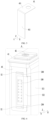
FIG 4 is an explosive schematic diagram of a structure of a secondary battery disclosed in an embodiment of the present application; -
FIG 5 is a schematic structural diagram of a current collecting member according to an embodiment of the present application; -
FIG 6 is an enlarged view of portion A inFIG 4 ; -
FIG 7 is a schematic structural diagram of a transition connecting piece disclosed in an embodiment of the present application; -
FIG 8 is a schematic structural diagram of a transition connecting piece disclosed in another embodiment of the present application; -
FIG 9 is a schematic structural diagram of a transition connecting piece disclosed in a further embodiment of the present application; -
FIG 10 is a schematic structural diagram of a transition connecting piece disclosed in another further embodiment of the present application; -
FIG 11 is a partial schematic diagram of a structure of a secondary battery disclosed in another embodiment of the present application; -
FIG 12 is an explosive schematic diagram of a structure of a secondary battery disclosed in a further embodiment of the present application; -
FIG 13 is a partial schematic diagram of a structure of a secondary battery disclosed in another further embodiment of the present application. - In the drawings, the drawings are not drawn to actual scale.
-
- 1, vehicle;
- 10, battery pack;
- 20, battery module;
- 30, secondary battery; 31, casing; 32, electrode assembly; 321, main body portion; 321a, end surface; 322, tab;
- 40, cap assembly; 41, cap plate; 42, electrode terminal; 43, current collecting member; 431, terminal connecting section; 432, guiding section; 432a, leg;
- 50, transition connecting piece; 51, current collecting portion; 51a, accommodating recess; 52, fixing portion;
- 60, first sheet; 70, second sheet; 80, third sheet; 90, busbar; 100, first connection region; 200, second connection region;
- X, length direction; Y, thickness direction; Z, width direction.
- The implementations of the present application are described below in further detail with reference to the accompanying drawings and embodiments. The following detailed description of the embodiments and the accompanying drawings are used to exemplarily illustrate the principle of the present application, but cannot be used to limit the scope of the present application, that is, the present application is not limited to the described embodiments.
- In the description of the present application, it should be noted that, unless otherwise stated, "multiple" means two or more; the orientation or positional relationship indicated by the terms "upper", "lower", "left", "right", "inside", "outside" or the like is merely used for convenience of describing the application and simplifying the description, rather than indicating or implying that the device or element referred to must have a particular orientation, or be constructed and operated in a particular orientation, and therefore cannot be understood as a limitation to the present application. In addition, the terms "first", "second", "third", or the like are only used for descriptive purposes, and cannot be understood as indicating or implying relative importance. "Perpendicularity" does not mean a strict perpendicularity, but allows an error within an allowed range. "Parallel" does not mean a strict parallel but allows an error within an allowed range.
- The orientation words appearing in the following description all refer to the directions shown in the drawings, and are not intended to define the specific structure of the present application. In the description of the present application, it should also be noted that, unless otherwise clearly defined and specified, the terms "install", "connect", and "couple" should be understood in a broad sense, for example, may refer to a fixed connection, a detachable connection, or an integral connection, may refer to a direct connection or an indirect connection through an intermediate medium. For the person skilled in the art, the specific meaning of the above-mentioned terms in the present application can be understood according to specific circumstances.
- In order to better understand the present application, the embodiments of the present application are described below in combination with
FIGS. 1-13 . - The embodiment of the present application provides an apparatus that uses a
secondary battery 30 as a power source. The apparatus may be but is not limited to, a vehicle, a ship, or an aircraft. Referring toFIG 1 , an embodiment of the present application provides avehicle 1 including a vehicle body and a battery block. The battery block is provided on the vehicle body. Thevehicle 1 may be a pure electric vehicle, a hybrid electric vehicle or an extended-range vehicle. The vehicle body is provided with a drive motor electrically connected to the battery block. The battery block provides power to the drive motor. The drive motor is connected to wheels on the vehicle body through a transmission mechanism to drive the vehicle to travel. Optionally, the battery block may be horizontally arranged at the bottom of the vehicle body. - As shown in
FIG 2 , the battery block may be formed as abattery pack 10. Thebattery pack 10 may be provided in various manners. In some optional embodiments, thebattery pack 10 includes a housing and abattery module 20 disposed in the housing. There may be one ormore battery modules 20. The one ormore battery modules 20 are arranged in a row in the housing. The type of the housing is not limited. The housing may be a frame-shaped housing, a disc-shaped housing, or a box-shaped housing. Optionally, the housing includes a lower housing for receiving thebattery module 20 and an upper housing for closing the lower housing. After closing the lower housing, the upper housing together with the lower housing forms an accommodating portion for accommodating thebattery module 20. In other optional embodiments, thebattery pack 10 includes a housing and a plurality ofsecondary batteries 30 directly arranged in the housing. - As shown in
FIG 3 , the battery block may also be formed as abattery module 20, and a plurality ofbattery modules 20 are arranged in a housing and installed on the vehicle body. - As shown in
FIG 3 , thebattery module 20 includes a plurality ofsecondary batteries 30. Thebattery module 20 may be provided in various manners. In one embodiment, thebattery module 20 includes an accommodating portion and a plurality ofsecondary batteries 30 located in the accommodating portion. The plurality ofsecondary batteries 30 are arranged side by side in the accommodating portion. The accommodating portion may be provided in various manners, and for example, the accommodating portion includes a shell and a cover plate covering the shell; or, the accommodating portion includes side plates and end plates that are connected one after another and define an enclosure; or, the accommodating portion includes two ends plates arranged oppositely and a strap band surrounding the end plates and thesecondary batteries 30. - As shown in
FIG 4 , thesecondary battery 30 according to the embodiment of the present application includes acasing 31, anelectrode assembly 32 disposed in thecasing 31, and acap assembly 40 hermetically connected with thecasing 31. - The
casing 31 according to the embodiment of the present application is formed in a cubic shape or other shapes. Thecasing 31 includes an internal space for accommodating theelectrode assembly 32 and electrolyte, and an opening communicating with the internal space. Thecasing 31 may be made of materials such as aluminum, aluminum alloy, plastic or other else. - The
electrode assembly 32 according to the embodiment of the present application can be formed by stacking or winding a first electrode plate, a second electrode plate, and a separator located between the first electrode plate and the second electrode plate, wherein the separator is an insulating member between the first electrode plate and the second electrode plate. - In the present embodiment, the description is made by exemplarily taking the first electrode plate as a positive electrode plate and taking the second electrode plate as a negative electrode plate. Both the positive electrode plate and the negative electrode plate include coated regions and uncoated regions, a positive electrode plate active material is coated on the coated region of the positive electrode plate, and a negative electrode plate active material is coated on the coated region of the negative electrode plate. On the coated region, the active material is coated on a region corresponding to a current collector formed by a thin metal foil. On the uncoated region, the current collector is directly exposed and no active material is coated. After being wound or stacked, the
electrode assembly 32 includes twotabs 322, namely, a positive tab and a negative tab. The coated regions of the positive electrode plate and the coated regions of the negative electrode plate constitute themain body portion 321. The uncoated regions of the positive electrode plate are stacked to form the positive tab, and the uncoated regions of the negative electrode plate are stacked to form the negative tab. Thetab 322 includes a plurality of layer structures. In the embodiment of the present application, themain body portion 321 includes twoend surfaces 321a disposed opposite to each other in a length direction X, and the positive and negative tabs respectively extend out from the twoend surfaces 321a of themain body portion 321 opposite to each other in the length direction X. - In the embodiment in which the
electrode assembly 32 is in a wound configuration, theelectrode assembly 32 as a whole are formed as a flat member. Theelectrode assembly 32 includes a wide surface and a narrow surface alternately arranged in a circumferential direction, wherein the wide surface is approximately parallel to a winding axis and is an outer surface which has the largest area. The wide surface may be a relatively flat surface, while not required to be a perfect flat plane. During use of thesecondary battery 30, theelectrode assembly 32 may expand, which may cause the wide surface to be slightly deformed. In the present embodiment, the length direction X of theelectrode assembly 32 is parallel to the winding axis and approximately parallel to the wide surface, and a thickness direction Y refers to a direction perpendicular to the wide surface. The length direction X and the thickness direction Y are perpendicular to a width direction Z, respectively. - In the embodiment where the
electrode assembly 32 is in a stacked configuration, the length direction X of theelectrode assembly 32 refers to a direction perpendicular to theend surface 321a of themain body portion 321 from which thetab 322 extends out, and the thickness direction Y refers to a stacking direction of the first electrode plate, the separator, and the second electrode plate. The length direction X and the thickness direction Y are perpendicular to the width direction Z, respectively. - Referring to
FIG 4 andFIG 5 , thecap assembly 40 according to the embodiment of the present application includes acap plate 41, anelectrode terminal 42 and a current collectingmember 43. Thecap plate 41 according to the embodiment of the present application includes an outer surface and an inner surface opposite each other in the width direction Z of theelectrode assembly 32 and an electrode lead-out hole (not shown in the drawings) penetrating through thecap plate 41 in the width direction Z. Thecap plate 41 can close the opening of thecasing 31 and is hermetically connected to thecasing 31. Theelectrode terminal 42 is provided on thecap plate 41 and disposed corresponding to the electrode lead-out hole. Theelectrode terminal 42 is at least partially exposed from the outer surface of thecap plate 41 for welding with abusbar 90. The current collectingmember 43 is adapted to connect thetab 322 with theelectrode terminal 42. The current collectingmember 43 includes aterminal connecting section 431 and aguiding section 432. Theterminal connecting section 431 is adapted to connect with theelectrode terminal 42, and theguiding section 432 is adapted to connect with thetab 322. The plane where theterminal connecting section 431 is located, is perpendicular to the width direction Z of theelectrode assembly 32 and is approximately parallel to the plane wherein thecap plate 41 is located. The plane where the guidingsection 432 is located, is perpendicular to the length direction X of theelectrode assembly 32 and is approximately parallel to theend surface 321a of themain body portion 321. In one example, theterminal connecting section 431 and theguiding section 432 are intersected, forming an L-shaped member. - After realizing the problem of a poor current flowing capability of the connection region between the
tab 322 and the current collectingmember 43, Applicant conducted research and analysis on various components of thesecondary battery 30. Applicant found that in the process of connecting thetab 322 with the current collectingmember 43, in order to ensure the connection strength between thetab 322 and the current collectingmember 43, the multiple layer structures of thetab 322 are usually pre-connected, and then thetab 322 after the pre-connection is operated again to connect with the current collectingmember 43, which causes thetab 322 to undergo two connecting operations at a same region, and the connection regions of the two connecting operations overlap or at partially overlap in their projections on a plane perpendicular to the length direction X, thereby causing damage to thetab 322 in these regions, and thus affecting the current flowing capability of thetab 322. - In view of the above-mentioned problem found by Applicant, Applicant has improved the configuration of the
secondary battery 30, and the embodiments of the present application will be further described below. - Referring to
FIGS. 4 and6 , thesecondary battery 30 provided by the embodiment of the present application further includes atransition connecting piece 50. Thetransition connecting piece 50 and the current collectingmember 43 are separately provided and connected to each other. The so-called "separately provided" means that thetransition connecting piece 50 and the current collectingmember 43 are two separately processed parts before being connected. The specific ways of connecting thetransition connecting piece 50 with the current collectingmember 43 include riveting, welding, and bonding. Thetransition connecting piece 50 is adapted to connecting thetab 322 with the guidingsection 432 of the current collectingmember 43. As shown inFIG 7 , thetransition connecting piece 50 includes acurrent collecting portion 51 and a fixingportion 52. Thecurrent collecting portion 51 is adapted to connect with thetab 322 and form afirst connection region 100, and the fixingportion 52 is adapted to connect with the guidingsection 432 and form asecond connection region 200. Projections of thefirst connection region 100 and thesecond connection region 200 on a plane perpendicular to the length direction X do not overlap. - As shown in
FIG 6 , thefirst connection region 100 and thesecond connection region 200 are spaced apart in the width direction Z, so that their respective projections on a plane perpendicular to the length direction X do not overlap. In some other examples, thefirst connection region 100 and thesecond connection region 200 may be spaced apart in the thickness direction Y, so that their respective projections on a plane perpendicular to the length direction X do not overlap. - Referring to
FIG 5 and FIG 6 , in thesecondary battery 30 according to the embodiment of the present application, thetab 322 of the electrode assembly and the current collectingportion 51 of thetransition connecting piece 50 are connected to form thefirst connection region 100, so that the multiple layer structures of thetab 322 and the current collectingportion 51 are pre-connected together to prevent looseness among the layer structures. In other words, by pre-connecting the various layer structures of thetab 322 together, the gap between the various layer structures can be reduced. Meanwhile, in the process of connecting the various layer structures of thetab 322, thetransition connecting piece 50 can also protect thetab 322, thereby preventing thetab 322 from being damaged. The fixingportion 52 of thetransition connecting piece 50 and theguiding section 432 of the current collectingmember 43 are connected to form thesecond connection region 200, so that thetab 322 is electrically connected to theguiding section 432 through thetransition connecting piece 50, without directly connecting thetab 322 to theguiding section 432. The electrical signal can be transmitted from thetab 322 to the current collectingportion 51, from the current collectingportion 51 to the fixingportion 52, and then from the fixingportion 52 to theguiding section 432 in order. Since after providing thetransition connecting piece 50, thefirst connection region 100 and thesecond connection region 200 can be independent of each other without interfering with each other, when achieving the connection of thetab 322 with the guidingsection 432, thefirst connection region 100 and thesecond connection region 200 do not overlap, and thetab 322 undergoes only one connecting operation when connected to the current collectingportion 51. As such, during the process of connecting thetab 322 with the current collectingmember 43, thetab 322 will not undergo two connecting operations at a same region, which effectively reduces the possibility that micro cracks appear in at least some of the layer structures of thetab 322 and affect the current flowing capability of thetab 322 due to that thetab 322 undergoes two connecting operations at a same region. Further, in the prior art, the current collectingmember 43 includes a bending section integrally formed with the guidingsection 432. The bending section needs to be bent after connected to thetab 322. In the process of bending the bending section, the guidingsection 432 will be stressed and deformed toward themain body portion 321 of theelectrode assembly 32, and thus there is a risk that the guidingsection 432 interferes with themain body portion 321 and causes themain body portion 321 to be damaged or short-circuited. In the embodiment of the present application, since thetab 322 is pre-connected with thetransition connecting piece 50, and then thetransition connecting piece 50 is connected with the guidingsection 432, and thetransition connecting piece 50 is formed separately from the current collectingmember 43 and does not need to be bent, the guidingsection 432 will not be deformed toward themain body portion 321 of theelectrode assembly 32, thereby reducing the possibility of interference between the guidingsection 432 and themain body portion 321. - In one embodiment, the
tab 322 is welded to the current collectingportion 51 to form thefirst connection region 100. Optionally, thetab 322 and the current collectingportion 51 are welded by ultrasonic welding, which is beneficial to improve the reliability of the connection between thetab 322 and the current collectingportion 51, and meanwhile can reduce the possibility of structural damage to thetab 322 when thetab 322 is welded. The fixingportion 52 is welded to theguiding section 432 to form thesecond connection region 200. Optionally, the fixingportion 52 and theguiding section 432 are welded by laser welding, which is beneficial for improving the reliability of the connection between the fixingportion 52 and theguiding section 432. During the connection process of thetab 322, thetransition connecting piece 50 and theguiding section 432, thetab 322 and the current collectingportion 51 are both placed between an upper clamp and a lower clamp on an ultrasonic welding device to complete the welding operation, and then thetransition connecting piece 50 and theguiding section 432 are placed in a laser welding device to complete the welding operation. If thetab 322 is directly welded to theguiding section 432, thetab 322 will undergo a ultrasonic welding at first, then a laser welding at a same region, and in this case, thetab 322 that has experienced the ultrasonic welding operation will then be subjected to the laser welding operation, and thus structural damage such as micro cracks tends to appear in thetab 322. In the present embodiment, since the regions of ultrasonic welding and laser welding do not overlap, thetab 322 is prevented from undergoing two connecting operations of ultrasonic welding and laser welding at a same region, the possibility that the structural damage such as micro cracks appears in thetab 322 is reduced, and thus it is ensured that thetab 322 has a good current flowing capacity. - In one embodiment, referring to
FIG 6 andFIG 7 , the region of thetransition connecting piece 50 covered by thetab 322 forms the current collectingportion 51. Here, the region of thetransition connecting piece 50 covered by thetab 322 refers to the portion of thetransition connecting piece 50 blocked by thetab 322 while observed along the length direction X. The region of thetransition connecting piece 50 which is not covered by thetab 322 forms the fixingportion 52. Here, the region of thetransition connecting piece 50 which is not covered by thetab 322 refers to the portion of thetransition connecting piece 50 which is not blocked by thetab 322 while observed along the length direction X. - In one embodiment, the fixing
portion 52 is located on one side of thetab 322 in the width direction Z, so that the size of thetransition connecting piece 50 in the thickness direction Y can be reduced, that is, the width of thetransition connecting piece 50 can be reduced. At least part of the current collectingportion 51 is connected to thetab 322 to form thefirst connection region 100. In one example, thefirst connection region 100 is a continuous region, which is beneficial for improving the connection strength between the current collectingportion 51 and thetab 322. At least part of the fixingportion 52 is connected to theguiding section 432 to form thesecond connection region 200. Referring toFIG 6 , thetransition connecting piece 50 includes two fixingportions 52. The two fixingportions 52 are respectively located on two sides of the current collectingportion 51 in the width direction Z, that is, in the width direction Z, one fixingportion 52 is located on one side of thetab 322, and the other fixingportion 52 is located on another side of thetab 322. The two fixingportions 52 are respectively welded to theguiding section 432 to form twosecond connection regions 200, which is beneficial for improving the connection strength between thetransition connecting piece 50 and theguiding section 432, and reduce the possibility of detachment of thetransition connecting piece 50 from the guidingsection 432, and meanwhile is also beneficial for improving the current flowing capacity between thetransition connecting piece 50 and theguiding section 432. - In one embodiment, referring to
FIG 6 , thetransition connecting piece 50 is provided on a side of the guidingsection 432 away from themain body portion 321 in the length direction X, so that the welding operation between the fixingportion 52 and theguiding section 432 can be performed from a side of the guidingsection 432 away from themain body portion 321, which is beneficial for improving the convenience of welding operation for connecting the fixingportion 52 with the guidingsection 432, and meanwhile, thetransition connecting piece 50 will not occupy the space between the guidingsection 432 and themain body portion 321, a relatively large distance is maintained between the guidingsection 432 and themain body portion 321, which further reduces the possibility of structural damage to themain body portion 321 due to an external force. In the present embodiment, at least part of the fixingportion 52 is attached to a surface of the guidingsection 432. In one example, as shown inFIG 6 , an entire surface of the fixingportion 52 facing the guidingsection 432 is attached to theguiding section 432. In the present embodiment, thetab 322 is bent relative to the length direction X and connected to a surface of the current collectingportion 51 away from the guidingsection 432 in the length direction X. - In another embodiment, the
tab 322 is bent relative to the length direction X and is connected to a surface of the current collectingportion 51 close to theguiding section 432. Thetransition connecting piece 50 and theguiding section 432 clamp thetab 322 and thus can protect thetab 322 and thefirst connection region 100. In one example, as shown inFIG 8 , the current collectingportion 51 includes anaccommodating recess 51a. Theaccommodating recess 51a is formed by recessing a surface of the current collectingportion 51 close to theguiding section 432 toward a direction away from the guidingsection 432. Thetab 322 extends into theaccommodating recess 51a and is connected and fixed to the current collectingportion 51. In the length direction X, at least part of thetab 322 is accommodated in theaccommodating recess 51a. Preferably, in the length direction X, a depth of theaccommodating recess 51a is greater than a thickness of theentire tab 322, so that theentire tab 322 is accommodated in theaccommodating recess 51a. As such, on one hand, it is beneficial for saving space in the length direction X, thereby increasing the energy density of thesecondary battery 30; on the other hand, due to theaccommodating recess 51a, the current collectingportion 51 itself receives a smaller supporting stress from thetab 322 or even does not receive any supporting stress from thetab 322 after thetransition collecting piece 50 is connected to theguiding section 432, and thus, thesecond connection region 200 formed by the connection between the fixingportion 52 and theguiding section 432 receives a smaller supporting stress or even does not receive any supporting stress from thetab 322, thereby reducing the possibility of fracture and separation of thesecond connection region 200 formed by the connection between the fixingportion 52 and theguiding section 432 due to a relatively large tensile stress. - In one embodiment, referring to
FIG 7 and FIG 8 , thetransition connecting piece 50 is an integrally formed single-layer sheet. Thetransition connecting piece 50 can be manufactured by stamping or machining. The thickness direction of thetransition connecting piece 50 and the thickness direction of the guidingsection 432 are both parallel to the length direction X. In the present embodiment, thetransition connecting piece 50 is formed in a rectangular shape, but the shape of thetransition connecting piece 50 is not limited here, as long as thetransition connecting piece 50 can realize the function of connecting thetab 322 with the guidingsection 432. - In one embodiment, referring to
FIG 9 , thetransition connecting piece 50 includes afirst sheet 60, asecond sheet 70 and athird sheet 80. Thefirst sheet 60 and thesecond sheet 70 are stacked in the length direction X. Thethird sheet 80 is bent into an arc shape and connected between thefirst sheet 60 and thesecond sheet 70. Thetab 322 is connected with thefirst sheet 60 to form thefirst connection region 100. Before thetransition connecting piece 50 and thetab 322 are connected, thefirst sheet 60 and thesecond sheet 70 are provided in an open state, and it is available to connect and fix thetab 322 with thefirst sheet 60 at first, then bend thesecond sheet 70 and stack it with thefirst sheet 60. It facilitates welding thefirst sheet 60 of thetransition connecting piece 50 to thetab 322, thus reducing the difficulty of connecting thetransition connecting piece 50 with thetab 322. When connecting thetransition connecting piece 50 to theguiding section 432, thetransition connecting piece 50 is connected to theguiding section 432 through both of thefirst sheet 60 and thesecond sheet 70 to form thesecond connection region 200, thereby being beneficial for improving the connection strength between the fixingportion 52 of thetransition connecting piece 50 and theguiding section 432. In another embodiment, referring toFIG 10 , thesecond sheet 70 extends beyond thefirst sheet 60 in the width direction Z of theelectrode assembly 32. Thesecond sheet 70 is provided with the fixingportion 52. In the present embodiment, the portion of thesecond sheet 70 that extends beyond thefirst sheet 60 forms the fixingportion 52. - In one embodiment, along the thickness direction Y, the guiding
section 432 has two opposite edges. Thetab 322 bypasses the edge of the guidingsection 432 and is connected to a surface of the current collectingportion 51 away from themain body portion 321. An outer surface of thethird sheet 80 is formed as an arc-shaped surface. Thethird sheet 80 is located near a root portion of thetab 322, and thus can effectively reduce the scratching between thetab 322 and the edges of thefirst sheet 60 and/or thesecond sheet 70 of thetransition connecting piece 50 when thetab 322 is folded, which may cause thetab 322 pierced by the edges of thefirst sheet 60 and/or thesecond sheet 70, or cause a stress concentration on thetab 322 due to the squeeze of thefirst sheet 60 and/or thesecond sheet 70, which thus cause structural damage such as cracks in thetab 322. - In one embodiment, as shown in
FIG 11 , twotransition connecting pieces 50 are provided. In the length direction X, the twotransition connecting pieces 50 are stacked. Thecurrent collecting portions 51 of the twotransition connecting pieces 50 clamp and connect to thetab 322. At least one of the twotransition connecting pieces 50 is connected with thetab 322 to form thefirst connection region 100. Preferably, the twotransition connecting pieces 50 are both connected with thetab 322 to form thefirst connection region 100. The fixingportion 52 of at least one of the twotransition connecting pieces 50 is connected to theguiding section 432. Preferably, the fixingportions 52 of the twotransition connecting pieces 50 are both connected to theguiding section 432. - In one embodiment, two
electrode assemblies 32 are provided. The twoelectrode assemblies 32 are arranged side by side in the thickness direction Y of theelectrode assembly 32, and therespective tabs 322 are respectively connected to at least onetransition connecting piece 50. As shown inFIG 12 , twotransition connecting pieces 50 are provided on oneguiding section 432. The twotransition connecting pieces 50 are arranged side by side in the thickness direction Y Thetab 322 of one of the twoelectrode assemblies 32 is connected to the current collectingportion 51 of onetransition connecting piece 50, and thetab 322 of theother electrode assembly 32 is connected to the current collectingportion 51 of the othertransition connecting piece 50. - In one embodiment, the guiding
section 432 includes twolegs 432a. The twolegs 432a are spaced apart in the thickness direction Y of theelectrode assembly 32, which is beneficial for reducing the weight of the guidingsection 432 and improving the energy density of thesecondary battery 30. At least onetransition connecting piece 50 is provided on each of the twolegs 432a. Theelectrode assemblies 32 and thelegs 432a are set in one-to-one correspondence and have the same quantity. Referring to the embodiment shown inFIG 13 , the guidingsection 432 includes twolegs 432a. Each of the twolegs 432a is provided with onetransition connecting piece 50. Thetab 322 of one of the twoelectrode assemblies 32 is connected to the current collectingportion 51 of onetransition connecting piece 50, and thetab 322 of theother electrode assembly 32 is connected to the current collectingportion 51 of the othertransition connecting piece 50. - In the
secondary battery 30 according to the embodiment of the present application, thetab 322 of theelectrode assembly 32 is connected to theguiding section 432 of the current collectingmember 43 through atransition connecting piece 50. Thetab 322 of theelectrode assembly 32 and the current collectingportion 51 of thetransition connecting piece 50 are connected and form thefirst connection region 100. The fixingportion 52 of thetransition connecting piece 50 and theguiding section 432 of the current collectingmember 43 are connected and form thesecond connection region 200. By providing thetransition connecting piece 50, thefirst connection region 100 and thesecond connection region 200 can be made respectively independent without interfering with each other; therefore, when achieving the connection of thetab 322 with the guidingsection 432, thefirst connection region 100 and thesecond connection region 200 do not overlap, and thus thetab 322 undergoes only one connecting operation when connected to the current collectingportion 51. As such, during the connection process between thetab 322 and the current collectingmember 43, thetab 322 will not undergo two connecting operations at a same region, which effectively reduces the possibility that at least some of the layer structures of thetab 322 may experience micro cracks on them due to that thetab 322 undergoes two connecting operations at a same region, which may further decrease the current flowing capability of thetab 322. - The present application further provides a manufacturing method for the
secondary battery 30, the method includes steps of: - providing an
electrode assembly 32, theelectrode assembly 32 including amain body portion 321 and atab 322 extending out from themain body portion 321; - providing a current collecting
member 43, the current collectingmember 43 including aguiding section 432, and theguiding section 432 extending in a direction perpendicular to a length direction X of theelectrode assembly 32; - providing a
transition connecting piece 50, thetransition connecting piece 50 including acurrent collecting portion 51 and a fixingportion 52; and - connecting the current collecting
portion 51 with thetab 322 to form afirst connection region 100, and connecting the fixingportion 52 with the guidingsection 432 to form asecond connection region 200, wherein respective projections of thefirst connection region 100 and thesecond connection region 200 on a plane perpendicular to the length direction X do not overlap. - In one embodiment, the current collecting
portion 51 is welded to thetab 322 to form thefirst connection region 100. Optionally, thetab 322 and the current collectingportion 51 are welded by ultrasonic welding. The fixingportion 52 is welded to theguiding section 432 to form thesecond connection region 200. Optionally, the fixingportion 52 and theguiding section 432 are welded by laser welding. - In one embodiment, first the current collecting
portion 51 and thetab 322 are welded to form thefirst connection region 100, and then the fixingportion 52 and theguiding section 432 are welded to form thesecond connection region 200. During the connecting process of thetab 322, thetransition connecting piece 50 and theguiding section 432, thetab 322 and the current collectingportion 51 are placed between an upper clamp and a lower clamp on an ultrasonic welding equipment at the same time, completing the welding operation between thetab 322 and the current collectingportion 51, and then thetransition connecting piece 50 and theguiding section 432 are placed at a laser welding equipment, completing the welding operation of the fixedportion 52 and theguiding section 432. If thetab 322 is directly welded to theguiding section 432, a same region of thetab 322 will undergo a ultrasonic welding first and then a laser welding in sequence, in which case structural damage such as micro cracks tends to appear on thetab 322 after thetab 322 undergoes the laser welding. In the present embodiment, since the regions of ultrasonic welding and laser welding do not overlap, thetab 322 is prevented from undergoing two connecting operations of ultrasonic welding and laser welding at a same region, thus reducing the possibility of structural damage such as micro cracks of thetab 322 and ensuring a good current flowing capacity of thetab 322. - In the manufacturing method for the
secondary battery 30 according to the embodiment of the present application, through connecting the current collectingportion 51 of thetransition connecting piece 50 to thetab 322 of theelectrode assembly 32 in advance, and then connecting the fixingportion 52 of thetransition connecting piece 50 to theguiding section 432 of the current collectingmember 43, the connections of thetab 322, thetransition connecting piece 50 and theguiding section 432 are realized. Since the two connection positions are respectively located at the current collectingportion 51 and the fixingportion 52, thetab 322 undergoes only one connecting operation during connection to the current collectingportion 51, thus preventing a same region of thetab 322 from experiencing two connecting operations during direct connection of thetab 322 with the guidingsection 432, reducing a possibility of structural damage such as micro-crack of a same region of thetab 322 due to experiencing two times of connecting process, and ensuring a good current flowing capability of thetab 322. - The present application is not limited to the specific embodiments disclosed in the context, but includes all technical solutions falling within the scope of the claims.
Claims (15)
- A secondary battery (30), characterized in that, comprising:an electrode assembly (32) comprising a main body portion (321) and a tab (322) extending out from the main body portion (321);a current collecting member (43) comprising a guiding section (432), the guiding section (432) extending in a direction perpendicular to a length direction (X) of the electrode assembly (32);a transition connecting piece (50), the transition connecting piece (50) and the current collecting member (43) being formed as two separately processed parts before being connected, the transition connecting piece (50) extending in a width direction (Z) of the electrode assembly (32) perpendicular to the length direction (X), the transition connecting piece (50) comprising a current collecting portion (51) and a fixing portion (52), the current collecting portion (51) being adapted to connect with the tab (322) and to form a first connection region (100), the fixing portion (52) being adapted to connect with the guiding section (432) and to form a second connection region (200), and respective projections of the first connection region (100) and the second connection region (200) on a plane perpendicular to the length direction (X) do not overlap.
- The secondary battery (30) according to claim 1, characterized in that, the tab (322) is welded to the current collecting portion (51) to form the first connection region (100), and the fixing portion (52) is welded to the guiding section (432) to form the second connection region (200).
- The secondary battery (30) according to claim 1 or 2, characterized in that, a region of the transition connecting piece (50) covered by the tab (322) forms the current collecting portion (51), and a region of the transition connecting piece (50) not covered by the tab (322) forms the fixing portion (52).
- The secondary battery (30) according to claim 3, characterized in that, the fixing portion (52) is located on one side of the tab (322) in the width direction (Z) of the electrode assembly (32).
- The secondary battery (30) according to any of claims 1 to 4, characterized in that, the transition connecting piece (50) comprises two fixing portions (52), and the two fixing portions (52) are respectively located on two sides of the current collecting portion (51) in the width direction (Z) of the electrode assembly (32), and are respectively welded to the guiding section (432) to form two second connection regions (200).
- The secondary battery (30) according to any of claims 1 to 5, characterized in that, the transition connecting piece (50) is disposed on a side of the guiding section (432) away from the main body portion (321).
- The secondary battery (30) according to any of claims 1 to 6, characterized in that, the tab (322) is bent relative to the length direction (X) and connected to a surface of the current collecting portion (51) away from the guiding section (432).
- The secondary battery (30) according to any of claims 1 to 6, characterized in that, the tab (322) is bent relative to the length direction (X) and connected to a surface of the current collecting portion (51) close to the guiding section (432).
- The secondary battery (30) according to claim 8, characterized in that, the current collecting portion (51) comprises an accommodating recess (51a), the accommodating recess (51a) is recessed in a direction away from the guiding section (432), and the tab (322) extends into the accommodating recess (51a) and is connected and fixed with the current collecting portion (51).
- The secondary battery (30) according to any of claims 1 to 9, characterized in that, the transition connecting piece (50) is an integrally formed single-layer sheet.
- The secondary battery (30) according to any of claims 1 to 9, characterized in that, the transition connecting piece (50) comprises a first sheet (60), a second sheet (70) and a third sheet (80), the first sheet (60) and the second sheet (70) are stacked in the length direction (X), and the third sheet (80) is bent into an arc shape and connected between the first sheet (60) and the second sheet (70).
- The secondary battery (30) according to claim 11, characterized in that, the second sheet (70) extends beyond the first sheet (60) in the width direction (Z) of the electrode assembly (32), and a portion of the second sheet (70) extending beyond the first sheet (60) is connected to the guiding section (432).
- The secondary battery (30) according to any of claims 1 to 12, characterized in that, two transition connecting pieces (50) are provided, and the current collecting portions (51) of the two transition connecting pieces (50) clamp and connect to the tab (322);
the fixing portion (52) of at least one of the two transition connecting pieces (50) is connected to the guiding section (432). - The secondary battery (30) according to any of claims 1 to 13, characterized in that, two electrode assemblies (32) are provided, the two electrode assemblies (32) are arranged side by side in a thickness direction (Y) of the electrode assembly (32), and respective tabs (322) of the two electrode assemblies (32) are respectively connected to at least one of the transition connecting pieces (50).
- The secondary battery (30) according to any of claims 1 to 14, characterized in that, the guiding section (432) comprises two legs (432a), the two legs (432a) are spaced apart in a thickness direction (Y) of the electrode assembly (32), and each of the two legs (432a) is provided with at least one transition connecting piece (50).
Applications Claiming Priority (1)
| Application Number | Priority Date | Filing Date | Title |
|---|---|---|---|
| PCT/CN2020/089440 WO2021226756A1 (en) | 2020-05-09 | 2020-05-09 | Secondary battery and manufacturing method therefor, battery module, and apparatus |
Publications (3)
| Publication Number | Publication Date |
|---|---|
| EP4030537A1 EP4030537A1 (en) | 2022-07-20 |
| EP4030537A4 EP4030537A4 (en) | 2023-02-22 |
| EP4030537B1 true EP4030537B1 (en) | 2024-01-10 |
Family
ID=78526083
Family Applications (1)
| Application Number | Title | Priority Date | Filing Date |
|---|---|---|---|
| EP20935156.8A Active EP4030537B1 (en) | 2020-05-09 | 2020-05-09 | Secondary battery and manufacturing method therefor, battery module, and apparatus |
Country Status (4)
| Country | Link |
|---|---|
| US (1) | US11929510B2 (en) |
| EP (1) | EP4030537B1 (en) |
| CN (1) | CN113924685A (en) |
| WO (1) | WO2021226756A1 (en) |
Families Citing this family (3)
| Publication number | Priority date | Publication date | Assignee | Title |
|---|---|---|---|---|
| CN114614069B (en) * | 2022-05-09 | 2022-08-26 | 宁德时代新能源科技股份有限公司 | Battery cell, manufacturing method thereof, battery and electric device |
| CN115548346B (en) * | 2022-09-23 | 2024-02-20 | 厦门海辰储能科技股份有限公司 | Current collecting assembly and battery |
| CN117239251A (en) * | 2023-10-19 | 2023-12-15 | 宁夏宝丰昱能科技有限公司 | Manufacturing process of square battery and square battery |
Family Cites Families (13)
| Publication number | Priority date | Publication date | Assignee | Title |
|---|---|---|---|---|
| US9287550B2 (en) | 2012-06-11 | 2016-03-15 | Samsung Sdi Co., Ltd. | Rechargeable battery |
| KR102371193B1 (en) * | 2015-08-10 | 2022-03-07 | 삼성에스디아이 주식회사 | Secondary Battery |
| CN205385061U (en) | 2016-03-18 | 2016-07-13 | 宁德时代新能源科技股份有限公司 | Secondary battery |
| CN108428847B (en) | 2017-04-07 | 2023-08-29 | 宁德时代新能源科技股份有限公司 | secondary battery |
| KR102371196B1 (en) * | 2017-08-31 | 2022-03-07 | 삼성에스디아이 주식회사 | Secondary Battery |
| KR102606100B1 (en) * | 2018-01-17 | 2023-11-24 | 삼성에스디아이 주식회사 | Secondary battery |
| CN208507745U (en) * | 2018-07-13 | 2019-02-15 | 宁德时代新能源科技股份有限公司 | Secondary cell |
| CN209232866U (en) * | 2018-12-29 | 2019-08-09 | 宁德时代新能源科技股份有限公司 | Secondary cell and battery modules |
| CN209963180U (en) * | 2019-04-12 | 2020-01-17 | 宁德时代新能源科技股份有限公司 | Secondary battery |
| CN209658320U (en) * | 2019-05-24 | 2019-11-19 | 宁德时代新能源科技股份有限公司 | Battery unit and battery modules |
| CN210015907U (en) * | 2019-07-09 | 2020-02-04 | 宁德时代新能源科技股份有限公司 | Secondary battery |
| CN210136949U (en) * | 2019-08-29 | 2020-03-10 | 宁德时代新能源科技股份有限公司 | Secondary battery |
| CN111048728B (en) * | 2020-03-18 | 2020-06-23 | 江苏时代新能源科技有限公司 | Secondary battery, battery module, and device using secondary battery as power supply |
-
2020
- 2020-05-09 EP EP20935156.8A patent/EP4030537B1/en active Active
- 2020-05-09 CN CN202080005792.5A patent/CN113924685A/en active Pending
- 2020-05-09 WO PCT/CN2020/089440 patent/WO2021226756A1/en unknown
-
2022
- 2022-04-11 US US17/717,179 patent/US11929510B2/en active Active
Also Published As
| Publication number | Publication date |
|---|---|
| EP4030537A4 (en) | 2023-02-22 |
| US20220238890A1 (en) | 2022-07-28 |
| CN113924685A (en) | 2022-01-11 |
| WO2021226756A1 (en) | 2021-11-18 |
| US11929510B2 (en) | 2024-03-12 |
| EP4030537A1 (en) | 2022-07-20 |
Similar Documents
| Publication | Publication Date | Title |
|---|---|---|
| US11450931B2 (en) | Secondary battery, battery module, and device for using secondary battery as power source | |
| US11929510B2 (en) | Secondary battery and manufacturing method thereof, battery module, and apparatus | |
| US8765291B2 (en) | Rechargeable battery | |
| US8673470B2 (en) | Secondary cell | |
| US8623537B2 (en) | Rechargeable battery and battery module | |
| JP4918242B2 (en) | Secondary battery | |
| US11316235B2 (en) | Prismatic secondary battery, assembled battery using the same and method of producing the same | |
| US10177363B2 (en) | Prismatic secondary battery | |
| EP2337106A2 (en) | Rechargeable battery | |
| US20220285795A1 (en) | Secondary battery, battery module, and device using secondary battery as power supply | |
| JP2006019284A (en) | Secondary battery | |
| US20220223984A1 (en) | Rechargeable battery | |
| EP3490034B1 (en) | Electrode member, electrode assembly and rechargeable battery | |
| CN212011114U (en) | Secondary battery, battery module, and device using secondary battery as power supply | |
| EP3989352A1 (en) | Secondary battery, battery module, and device using battery as power source | |
| CN114639926A (en) | Battery and method for assembling battery | |
| EP4310977A1 (en) | Electrode sheet and preparation method therefor, battery, and electronic device | |
| US11271274B2 (en) | Secondary battery | |
| WO2017047789A1 (en) | Electricity storage element and method for manufacturing electricity storage element | |
| KR100277638B1 (en) | Electrode assembly manufacturing method and electrode assembly and battery using the electrode assembly | |
| JP2021120961A (en) | Square secondary battery and battery pack using the same | |
| CN219457789U (en) | Battery and battery device | |
| CN219534801U (en) | Battery and battery device | |
| CN216213948U (en) | Battery with a battery cell | |
| US20220085465A1 (en) | Current collecting member and manufacturing method thereof, secondary battery and manufacturing method thereof, battery module, and apparatus |
Legal Events
| Date | Code | Title | Description |
|---|---|---|---|
| STAA | Information on the status of an ep patent application or granted ep patent |
Free format text: STATUS: THE INTERNATIONAL PUBLICATION HAS BEEN MADE |
|
| PUAI | Public reference made under article 153(3) epc to a published international application that has entered the european phase |
Free format text: ORIGINAL CODE: 0009012 |
|
| STAA | Information on the status of an ep patent application or granted ep patent |
Free format text: STATUS: REQUEST FOR EXAMINATION WAS MADE |
|
| 17P | Request for examination filed |
Effective date: 20220413 |
|
| AK | Designated contracting states |
Kind code of ref document: A1 Designated state(s): AL AT BE BG CH CY CZ DE DK EE ES FI FR GB GR HR HU IE IS IT LI LT LU LV MC MK MT NL NO PL PT RO RS SE SI SK SM TR |
|
| A4 | Supplementary search report drawn up and despatched |
Effective date: 20230125 |
|
| RIC1 | Information provided on ipc code assigned before grant |
Ipc: H01M 50/103 20210101ALI20230119BHEP Ipc: H01M 50/533 20210101ALI20230119BHEP Ipc: H01M 50/169 20210101ALI20230119BHEP Ipc: H01M 50/147 20210101AFI20230119BHEP |
|
| DAV | Request for validation of the european patent (deleted) | ||
| DAX | Request for extension of the european patent (deleted) | ||
| GRAP | Despatch of communication of intention to grant a patent |
Free format text: ORIGINAL CODE: EPIDOSNIGR1 |
|
| STAA | Information on the status of an ep patent application or granted ep patent |
Free format text: STATUS: GRANT OF PATENT IS INTENDED |
|
| INTG | Intention to grant announced |
Effective date: 20231030 |
|
| GRAS | Grant fee paid |
Free format text: ORIGINAL CODE: EPIDOSNIGR3 |
|
| GRAA | (expected) grant |
Free format text: ORIGINAL CODE: 0009210 |
|
| STAA | Information on the status of an ep patent application or granted ep patent |
Free format text: STATUS: THE PATENT HAS BEEN GRANTED |
|
| AK | Designated contracting states |
Kind code of ref document: B1 Designated state(s): AL AT BE BG CH CY CZ DE DK EE ES FI FR GB GR HR HU IE IS IT LI LT LU LV MC MK MT NL NO PL PT RO RS SE SI SK SM TR |
|
| REG | Reference to a national code |
Ref country code: GB Ref legal event code: FG4D |
|
| REG | Reference to a national code |
Ref country code: CH Ref legal event code: EP |
|
| REG | Reference to a national code |
Ref country code: DE Ref legal event code: R096 Ref document number: 602020024337 Country of ref document: DE |
|
| REG | Reference to a national code |
Ref country code: IE Ref legal event code: FG4D |
|
| P01 | Opt-out of the competence of the unified patent court (upc) registered |
Effective date: 20240104 |