EP3730412A1 - Capturing system, aerospace vehicle, and plate-like body - Google Patents
Capturing system, aerospace vehicle, and plate-like body Download PDFInfo
- Publication number
- EP3730412A1 EP3730412A1 EP20167231.8A EP20167231A EP3730412A1 EP 3730412 A1 EP3730412 A1 EP 3730412A1 EP 20167231 A EP20167231 A EP 20167231A EP 3730412 A1 EP3730412 A1 EP 3730412A1
- Authority
- EP
- European Patent Office
- Prior art keywords
- magnetic force
- plate
- aerospace vehicle
- target object
- generating portion
- Prior art date
- Legal status (The legal status is an assumption and is not a legal conclusion. Google has not performed a legal analysis and makes no representation as to the accuracy of the status listed.)
- Granted
Links
- 230000002093 peripheral effect Effects 0.000 claims description 11
- XEEYBQQBJWHFJM-UHFFFAOYSA-N Iron Chemical compound [Fe] XEEYBQQBJWHFJM-UHFFFAOYSA-N 0.000 description 14
- 239000000696 magnetic material Substances 0.000 description 10
- PXHVJJICTQNCMI-UHFFFAOYSA-N Nickel Chemical compound [Ni] PXHVJJICTQNCMI-UHFFFAOYSA-N 0.000 description 8
- 229910052742 iron Inorganic materials 0.000 description 7
- 238000000034 method Methods 0.000 description 7
- 239000003550 marker Substances 0.000 description 5
- 229910000831 Steel Inorganic materials 0.000 description 4
- 238000010586 diagram Methods 0.000 description 4
- 229910052759 nickel Inorganic materials 0.000 description 4
- 229910000889 permalloy Inorganic materials 0.000 description 4
- 239000010959 steel Substances 0.000 description 4
- 238000013459 approach Methods 0.000 description 3
- 238000011161 development Methods 0.000 description 3
- 238000004519 manufacturing process Methods 0.000 description 3
- 239000000463 material Substances 0.000 description 3
- 239000011324 bead Substances 0.000 description 2
- 239000011521 glass Substances 0.000 description 2
- XAGFODPZIPBFFR-UHFFFAOYSA-N aluminium Chemical compound [Al] XAGFODPZIPBFFR-UHFFFAOYSA-N 0.000 description 1
- 229910052782 aluminium Inorganic materials 0.000 description 1
- 230000003247 decreasing effect Effects 0.000 description 1
- 238000013461 design Methods 0.000 description 1
- 239000012634 fragment Substances 0.000 description 1
- 238000003384 imaging method Methods 0.000 description 1
- 238000012986 modification Methods 0.000 description 1
- 230000004048 modification Effects 0.000 description 1
- 238000012545 processing Methods 0.000 description 1
Images


Classifications
-
- B—PERFORMING OPERATIONS; TRANSPORTING
- B64—AIRCRAFT; AVIATION; COSMONAUTICS
- B64G—COSMONAUTICS; VEHICLES OR EQUIPMENT THEREFOR
- B64G1/00—Cosmonautic vehicles
- B64G1/22—Parts of, or equipment specially adapted for fitting in or to, cosmonautic vehicles
- B64G1/66—Arrangements or adaptations of apparatus or instruments, not otherwise provided for
-
- B—PERFORMING OPERATIONS; TRANSPORTING
- B64—AIRCRAFT; AVIATION; COSMONAUTICS
- B64G—COSMONAUTICS; VEHICLES OR EQUIPMENT THEREFOR
- B64G1/00—Cosmonautic vehicles
- B64G1/22—Parts of, or equipment specially adapted for fitting in or to, cosmonautic vehicles
- B64G1/64—Systems for coupling or separating cosmonautic vehicles or parts thereof, e.g. docking arrangements
- B64G1/646—Docking or rendezvous systems
-
- G—PHYSICS
- G01—MEASURING; TESTING
- G01B—MEASURING LENGTH, THICKNESS OR SIMILAR LINEAR DIMENSIONS; MEASURING ANGLES; MEASURING AREAS; MEASURING IRREGULARITIES OF SURFACES OR CONTOURS
- G01B11/00—Measuring arrangements characterised by the use of optical techniques
- G01B11/26—Measuring arrangements characterised by the use of optical techniques for measuring angles or tapers; for testing the alignment of axes
-
- B—PERFORMING OPERATIONS; TRANSPORTING
- B64—AIRCRAFT; AVIATION; COSMONAUTICS
- B64G—COSMONAUTICS; VEHICLES OR EQUIPMENT THEREFOR
- B64G4/00—Tools specially adapted for use in space
- B64G2004/005—Robotic manipulator systems for use in space
Landscapes
- Engineering & Computer Science (AREA)
- Remote Sensing (AREA)
- Aviation & Aerospace Engineering (AREA)
- Physics & Mathematics (AREA)
- General Physics & Mathematics (AREA)
- Manipulator (AREA)
- Traffic Control Systems (AREA)
- Control Of Position, Course, Altitude, Or Attitude Of Moving Bodies (AREA)
- Road Signs Or Road Markings (AREA)
Abstract
Description
- The present subject disclosure relates to a capturing system, an aerospace vehicle, and a plate-like body.
- It is known that remains of space missions, such as artificial satellites which were launched in the past and completed their missions, broken and fragments thereof, or the upper stage of a rocket, are currently present as space debris (hereinafter referred to as "debris") on orbit around the earth. Such debris may collide with and damage operational space stations and artificial satellites. Therefore, various techniques of deorbiting and burning the debris in the atmosphere or collecting the debris have been proposed.
- For example, a technique has been proposed which includes bringing a mother unit close to the debris, capturing the debris by a robot arm provided on the mother unit, attaching a conductive tether device to the debris, , and decelerating the debris by an electromagnetic force acting on the tether (Japanese Patent Laid-Open No.
2004-98959 2016-68730 - However, in the capturing technique by the robot arm described in Japanese Patent Laid-Open No.
2004-98959 2016-68730 - The present subject disclosure has been made in view of such circumstances. The objective of the present subject disclosure is to increase the success rate of missions at a low cost for a capturing system which captures a target object in space.
- In order to achieve the objective, a capturing system according to the present subject disclosure captures a target object in space and has: a plate-like body which is attached to the target object and attracted with a magnetic force; and an aerospace vehicle that has a magnetic force generating portion which generates the magnetic force attracting the plate-like body. An aerospace vehicle according to the present subject disclosure has a magnetic force generating portion generating a magnetic force that enables capturing of a target object in space by attracting a plate-like body, which is attached to the target object and attracted with magnetic force, with magnetic force generated by the magnetic force generating portion. Furthermore, a plate-like body according to the present subject disclosure is attached to a target object in space before the target object is launched to space, and enables the aerospace vehicle to capture the target object by being attracted with magnetic force generated by the magnetic force generating portion of the aerospace vehicle.
- When such a configuration is employed, a target object in space can be captured by attaching a plate-like body, which is attracted with magnetic force, to the target object prior to launch, and then attracting the plate-like body with magnetic force generated by the magnetic force generating portion of the aerospace vehicle. The plate-like body which is attached to the target object prior to launch has no electrical or mechanical structures, and the mechanism of the magnetic force generating portion of the aerospace vehicle is relatively simple. Therefore, the development or manufacturing cost can be markedly reduced.
- The capturing system according to the present subject disclosure can employ a magnetic force generating portion that has a plate-like member and a magnetic portion placed on the surface of the plate-like member. Herein, two or more of the magnetic portions can be placed at a predetermined interval along the peripheral edge of the plate-like member.
- As the magnetic portion, a permanent magnet can be employed. Thus, the magnetic force generating portion can be configured at a relatively low cost. Moreover, an electromagnet that generates a magnetic force by applying an electric current may be employed as the magnetic portion. Thus, when the attachment between the magnetic force generating portion and the plate-like body is undesirable, for example, the electric current applied to the electromagnet is stopped to temporarily eliminate the magnetic force, whereby the undesired attachment can be canceled. Thereafter, by restarting the current application to the electromagnet as necessary, the attraction between the magnetic force generating portion and the plate-like body can be resumed.
- The capturing system according to the present subject disclosure can employ an aerospace vehicle that has a body and a rod-shaped member that may be deployed and retracted from the body. In such a case, the magnetic force generating portion can be attached to the tip of the rod-shaped member.
- When such a configuration is employed, the magnetic force generating portion is attached to the tip of the rod-shaped member that may be deployed and retracted from the body of the aerospace vehicle. Therefore, in capturing a target object, the rod-shaped member is deployed from the body of the aerospace vehicle to the plate-like body of the target object, so that the magnetic force generating portion can be brought close to the plate-like body. On the other hand, when the aerospace vehicle travels in space, the rod-shaped member can be retracted into the body. Therefore, the interference between portions other than the plate-like body of the target object, such as antennas, nozzles, or solar cells, and the rod-shaped member can be prevented. Moreover, by first contacting the target object with the tip (magnetic force generating portion) of the rod-shaped member placed on the aerospace vehicle, the action of the load of the entire aerospace vehicle on the target object can be prevented. Therefore, the influence on the target object can be minimized.
- In the capturing system according to the present subject disclosure, the plate-like body can have a portion containing magnetic materials, such as iron, nickel, permalloy, steel, and others.
- According to the present subject disclosure, for the capturing system which captures a target object in space, such as debris, the success rate of a mission thereof can be increased at a low cost.
-
-
FIG. 1 is a configuration diagram for explaining the entire configuration of a capturing system according to an embodiment of the present subject disclosure. -
FIG. 2 is a plan view of a plate-like body configuring the capturing system according to the embodiment of the present subject disclosure. -
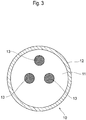
FIG. 3 is a structure diagram for explaining the internal structure of the plate-like body illustrated inFIG. 2 . -
FIG. 4 is a perspective diagram of an aerospace vehicle configuring the capturing system according to the embodiment of the present subject disclosure. -
FIG. 5 is a perspective diagram illustrating a state where a rod-shaped member of the aerospace vehicle illustrated inFIG. 4 is retracted into the body. -
FIG. 6 is a front view of a magnetic force generating portion of the aerospace vehicle illustrated inFIG. 4 . -
FIG. 7 is a front view of a modification of the magnetic force generating portion of the aerospace vehicle illustrated inFIG. 4 . - Hereinafter, an embodiment of the present subject disclosure is described with reference to the drawings.
- First, the configuration of a capturing
system 1 according to the embodiment of the present subject disclosure is described with reference toFIG. 1 to FIG. 7 . - The capturing
system 1 according to this embodiment is one for capturing a target object (for example, debris) T in space, which has a plate-like body 10 attached to the target object T and anaerospace vehicle 20 having a magnetic force generating portion 23 (described later) generating magnetic a force that attracts the plate-like body 10, as illustrated inFIG. 1 . - As illustrated in
FIG. 2 andFIG. 3 , the plate-like body 10 is a plate-like member having a circular shape as viewed in a plan view, has a predetermined thickness, and is attached beforehand to a predetermined portion (for example, a flat portion) of the target object T. - The plate-
like body 10 in this embodiment has acentral portion 11 containing aluminum and aperipheral portion 12 containing iron as illustrated inFIG. 3 , and is configured so that theperipheral portion 12 containing iron, which is a magnetic material, is attracted to the magneticforce generating portion 23 of theaerospace vehicle 20. Theperipheral portion 12 can also contain other magnetic materials (for example, nickel, permalloy, steel, etc.) in place of iron. Both thecentral portion 11 and theperipheral portion 12 may contain magnetic materials, such as iron. The area of the plate-like body 10 can be set to be either equal to or slightly larger than the area of the magneticforce generating portion 23 of theaerospace vehicle 20. - In the
central portion 11 of the plate-like body 10,markers 13 can be placed for approach navigation of theaerospace vehicle 20. Themarkers 13 show a certain geometric pattern, and three or more circles can be arranged in a predetermined pattern. Themarkers 13 contain materials (for example, glass beads, a corner cube mirror, etc.) capable of reflecting light emitted from theaerospace vehicle 20 directly towards theaerospace vehicle 20. In order to specify the position and the movement of the plate-like body 10, at least threemarkers 13 are preferably placed. In order to prevent damage to the plate-like body 10 during magnetic attraction, specific surface processing can be applied to the plate-like body 10. - The
aerospace vehicle 20 is configured so as to be attached to a rocket and launched into space, and then separated from the rocket to be autonomously movable in the space and has abody 21 having an approximately rectangular parallelepiped shape and a rod-shaped member 22 having an approximately cylindrical shape projectable and retractable from thebody 21 as illustrated inFIG. 4 . When theaerospace vehicle 20 is launched or moves in the space, theaerospace vehicle 20 is set to a state where the rod-shaped member 22 is retracted into thebody 21 as illustrated inFIG. 5 . - The magnetic
force generating portion 23 generating magnetic force attracting the plate-like body 10 to the target object T is attached to the tip of the rod-shaped member 22 of theaerospace vehicle 20. The magneticforce generating portion 23 has a plate-like member 23a having a circular shape as viewed in a plan view andmagnetic portions 23b provided on the surface of the plate-like member 23a as illustrated inFIG. 6 . In this embodiment, a permanent magnet having a circular shape as viewed in a plan view is employed as themagnetic portion 23b and two or more of the permanent magnets are provided at a predetermined interval along the peripheral edge of the plate-like member 23a as illustrated inFIG. 6 . The magnetic force generated by the magneticforce generating portion 23 is set to a value (for example, 4 N) with which the plate-like body 10 can be attracted. - The
aerospace vehicle 20 can facilitate the navigation when approaching by recognizing themarkers 13 or the like attached to the central portion of the plate-like body 10 with acamera 24 or the like of theaerospace vehicle 20 as illustrated inFIG. 6 . - In the
aerospace vehicle 20, the area permagnetic portion 23b, the position and the number of themagnetic portions 23b, and the like can be altered as appropriate. For example, in place of providing themagnetic portions 23b having a relatively large area as illustrated inFIG. 6 , a large number ofmagnetic portions 23b having a relatively small area can also be provided as illustrated inFIG. 7 . - Next, a method for capturing the target object T using the
capturing system 1 according to the embodiment of the present subject disclosure is described. - First, the
aerospace vehicle 20 is moved towards the target object T. Herein, theaerospace vehicle 20 searches for the plate-like body 10 attached to the target object T while performing imaging with thecamera 24. The search of the plate-like body 10 is completed through reflecting light emitted from a light projector on the surface of themarkers 13 attached to the surface of the plate-like body 10, capturing the light with thecamera 24, and then recognizing the same by an arithmetic operation portion, for example. By recognizing the relative position and the relative attitude of the target object T from, for example, information obtained by recognizing the pattern of themarkers 13 on the surface of the plate-like body 10, theaerospace vehicle 20 is movable so as to approach the target object T. - Subsequently, when the distance between the target object T and the
aerospace vehicle 20 reaches a value equal to or smaller than a predetermined value, the rod-shapedmember 22 of theaerospace vehicle 20 is projected from thebody 21 to the plate-like body 10 of the target object T. Then, the plate-like body 10 attached to the target object T beforehand is attracted with magnetic force generated by the magneticforce generating portion 23 attached to the tip of the rod-shapedmember 22 of theaerospace vehicle 20. Then, the rod-shapedmember 22 of theaerospace vehicle 20 is retracted into thebody 21 side, whereby the target object T is brought close to theaerospace vehicle 20 to be captured. - In the
capturing system 1 according to the embodiment described above, the plate-like body 10 to be attracted with magnetic force is attached to the target object T in the space beforehand, and then the plate-like body 10 is attracted with magnetic force generated by the magneticforce generating portion 23 of theaerospace vehicle 20, whereby the target object T can be captured. The plate-like body 10 attached to the target object T beforehand has no electrical and mechanical structures and the mechanism of the magneticforce generating portion 23 of theaerospace vehicle 20 is also relatively simple, and therefore the development/manufacturing cost can be markedly reduced. - In the
capturing system 1 according to the embodiment described above, the permanent magnet is employed as themagnetic portion 23b, and therefore the magneticforce generating portion 23 can be configured at a relatively low cost. - Moreover, in the
capturing system 1 according to the embodiment described above, the magneticforce generating portion 23 is attached to the tip of the rod-shapedmember 22 projectably and retractably provided to thebody 21 of theaerospace vehicle 20. Therefore, when capturing the target object T, the magneticforce generating portion 23 can be brought close to the plate-like body 10 by projecting the rod-shapedmember 22 from thebody 21 of theaerospace vehicle 20 to the plate-like body 10 of the target object T. On the other hand, when theaerospace vehicle 20 travels in the space, the rod-shapedmember 22 can be retracted into thebody 21. Therefore, the interference between the other portions (portions other than the plate-like body 10, such as an antenna, a nozzle, and a solar cell) and the rod-shapedmember 22 of the target object T can be prevented. Moreover, by first contacting the target object T with the tip (magnetic force generating portion 23) of the rod-shapedmember 22 provided to theaerospace vehicle 20, the action of the load of theentire aerospace vehicle 20 on the target object T can be prevented. Therefore, the influence on the target object T can be minimized. - This embodiment describes the example in which a permanent magnet is employed as the
magnetic portion 23b configuring the magneticforce generating portion 23 but an electromagnet generating magnetic force by current application can also be employed in place of the permanent magnet. Thus, when the attraction state between the magneticforce generating portion 23 and the plate-like body 10 is inappropriate, for example, the current application to the electromagnet is stopped to temporarily eliminate the magnetic force, whereby the inappropriate attraction state can be canceled. Thereafter, by restarting the current application to the electromagnet as necessary, the attraction between the magneticforce generating portion 23 and a plate-like body 10 can be realized again. - Moreover, by combining an electromagnet and a permanent magnet, the magnetic force of the permanent magnet can be eliminated by current application. Thus, continuous power is not required in the attraction state and, when the magnetic
force generating portion 23 and the plate-like body 10 enter an inappropriate attraction state, the inappropriate attraction state can be cancelled by current application for a short period of time. Thereafter, by restarting the current application to the electromagnet as necessary, the attraction between the magneticforce generating portion 23 and the plate-like body 10 can be realized again. - Moreover, in this embodiment, the plane shape of the plate-
like body 10 to be attached to the target object T is set to a circular shape but the plane shape of the plate-like body 10 is not limited to the circular shape and may be a polygonal shape (triangular shape, square shape, hexagonal shape, and the like), for example. The plane shape of the plate-like member 23a of the magneticforce generating portion 23 of theaerospace vehicle 20 is also not limited to the circular shape and can be set to a polygonal shape, for example. Moreover, the shape of theaerospace vehicle 20 is also not limited to the approximately rectangular parallelepiped shape and can be set to an approximately columnar shape, for example. - The present subject disclosure is not limited to the embodiment described above and embodiments obtained by adding design changes to the embodiment described above as appropriate by a person skilled in the art are also included in the scope of the present subject disclosure insofar as the embodiments have the features of the present subject disclosure. More specifically, the elements of the embodiment described above and the arrangement, materials, conditions, shapes, sizes, and the like thereof are not necessarily limited to those described as examples and can be altered as appropriate. Moreover, the elements of the embodiment described above can be combined as long as the combination is technically allowed and those obtained by combining the elements are also included in the scope of the present subject disclosure insofar as the combinations include the features of the present subject disclosure.
- This section describes additional aspects and features of the methods and apparatuses of the present subject disclosure:
- A1 A capturing system that captures a target object in the space, and has: a plate-like body that is attached to the target object and attracted with magnetic force, and an aerospace vehicle that has a magnetic force generating portion which generates the magnetic force attracting the plate-like body.
- A2 The capturing system according to A1, wherein the magnetic force generating portion has a plate-like member and a magnetic portion provided on a surface of the plate-like member.
- A3 The capturing system according to A2, wherein two or more of the magnetic portions are provided at a predetermined interval along the peripheral edge of the plate-like member.
- A4 The capturing system according to A2 or A3, wherein the magnetic portion is a permanent magnet.
- A5 The capturing system according to A2 or A3, wherein the magnetic portion is an electromagnet that generates magnetic force by current application.
- A6 The capturing system according to any one of A1 to A5, wherein: the aerospace vehicle has a body and a rod-shaped member projectably and retractably provided to the body, and the magnetic force generating portion is attached to the tip of the rod-shaped member.
- A7 The capturing system according to any one of A1 to A6, wherein the plate-like body has a portion containing magnetic materials.
- A8 The capturing system according to A7, wherein the magnetic material is iron, nickel, permalloy, or steel.
- B1 An aerospace vehicle that has a magnetic force generating portion generating magnetic force, and enables capturing of a target object in the space by attracting a plate-like body, which is attached to the target object and attracted with magnetic force, with magnetic force generated by the magnetic force generating portion.
- C1 A plate-like body that is attached to a target object in the space before the target object is launched to the space, and enables the aerospace vehicle to capture the target object by being attracted with magnetic force generated in the magnetic force generating portion of the aerospace vehicle.
- D1. A plate-like body, that is attached to a target object in a space before the target object is launched to the space, the plate-like body comprising a marker for approach navigation of an aerospace vehicle.
- D2. The plate-like body according to D1, wherein the marker contains a material capable of reflecting light and reflects light emitted from the aerospace vehicle towards the aerospace vehicle.
- D3. The plate-like body according to D2, wherein the marker contains glass beads or a mirror.
- D4. The plate-like body according to any one of D1 to D3, wherein at least three pieces of the marker are provided.
- D5. The plate-like body according to any one of D1 to D4, wherein the markers show a certain geometric pattern.
- D6. The plate-like body according to D5, wherein the markers are circles located in a predetermined pattern.
- D7. The plate-like body according to any one of D1 to D6, comprising a portion containing a magnetic material.
- D8. The plate-like body according to D7, comprising a peripheral portion and a central portion, wherein the peripheral portion containing a magnetic material, and the markers are placed in the central portion.
- D9. The plate-like body according to D7 or D8, wherein the magnetic material is iron, nickel, permalloy, or steel.
- E1. A capturing system, which captures a target object in a space, the capturing system comprising: the plate-like body according to any one of D7 to D9; and an aerospace vehicle that has a magnetic force generating portion which generates magnetic force attracting the plate-like body.
- E2. The capturing system according to E1, wherein the magnetic force generating portion has a plate-like member and a magnetic portion placed on a surface of the plate-like member.
- E3. The capturing system according to E2, wherein the magnetic portion is a permanent magnet.
- E4. The capturing system according to E2, wherein the magnetic portion is an electromagnet that generates magnetic force by applying current.
- E5. The capturing system according to any one of E1 to E4, wherein the aerospace vehicle has a body and a rod-shaped member projectable and retractable from the body, wherein the magnetic force generating portion is attached to a tip of the rod-shaped member.
- F1. An aerospace vehicle comprising a magnetic force generating portion that generates magnetic force, wherein the aerospace vehicle enables capturing a target object in a space by attracting the plate-like body according to any one of Claims 7 to 9 with magnetic force generated by the magnetic force generating portion.
-
- 1: Capturing system
- 10: Plate-like body
- 11: Central portion
- 12: Peripheral portion (Portion containing magnetic materials)
- 13: Marker
- 20: Aerospace vehicle
- 21: Body
- 22: Rod-shaped member
- 23: Magnetic force generating portion
- 23a: Plate-like member
- 23b: Magnetic portion
- 24: Camera
- T: Target object
Claims (5)
- An aerospace vehicle (20) comprising: a body (21); a magnetic force generating portion (23) for generating a magnetic force; and a rod-shaped member (22) projectably and retractably provided to the body (21),wherein the aerospace vehicle (20) enables capturing a target object (T) in space by attracting a plate-like body (10) with magnetic force generated by the magnetic force generating portion (23), andwherein the magnetic force generating portion (23) is attached to a tip of the rod-shaped member (22).
- The aerospace vehicle (20) according to claim 1, wherein the magnetic force generating portion (23) has a plate-like member (23a) and a magnetic portion (23b) provided on the surface of the plate-like member (23a).
- The aerospace vehicle (20) according to claim 2, wherein two or more of the magnetic portions (23b) are placed at a predetermined interval along the peripheral edge of the plate-like member (23a).
- The aerospace vehicle (20) according to claim 2 or 3, wherein the magnetic portion (23b) is a permanent magnet.
- The aerospace vehicle (20) according to claim 2 or 3, wherein the magnetic portion (23b) is an electromagnet that generates a magnetic force by applying a current.
Applications Claiming Priority (2)
| Application Number | Priority Date | Filing Date | Title |
|---|---|---|---|
| JP2017025747 | 2017-02-15 | ||
| EP17165426.2A EP3363744B1 (en) | 2017-02-15 | 2017-04-07 | Capturing system, aerospace vehicle, and plate-like body |
Related Parent Applications (2)
| Application Number | Title | Priority Date | Filing Date |
|---|---|---|---|
| EP17165426.2A Division EP3363744B1 (en) | 2017-02-15 | 2017-04-07 | Capturing system, aerospace vehicle, and plate-like body |
| EP17165426.2A Division-Into EP3363744B1 (en) | 2017-02-15 | 2017-04-07 | Capturing system, aerospace vehicle, and plate-like body |
Publications (2)
| Publication Number | Publication Date |
|---|---|
| EP3730412A1 true EP3730412A1 (en) | 2020-10-28 |
| EP3730412B1 EP3730412B1 (en) | 2022-08-10 |
Family
ID=58994817
Family Applications (2)
| Application Number | Title | Priority Date | Filing Date |
|---|---|---|---|
| EP17165426.2A Active EP3363744B1 (en) | 2017-02-15 | 2017-04-07 | Capturing system, aerospace vehicle, and plate-like body |
| EP20167231.8A Active EP3730412B1 (en) | 2017-02-15 | 2017-04-07 | Aerospace vehicle for capturing a target object in space |
Family Applications Before (1)
| Application Number | Title | Priority Date | Filing Date |
|---|---|---|---|
| EP17165426.2A Active EP3363744B1 (en) | 2017-02-15 | 2017-04-07 | Capturing system, aerospace vehicle, and plate-like body |
Country Status (3)
| Country | Link |
|---|---|
| US (1) | US20180229865A1 (en) |
| EP (2) | EP3363744B1 (en) |
| JP (2) | JPWO2018150883A1 (en) |
Families Citing this family (7)
| Publication number | Priority date | Publication date | Assignee | Title |
|---|---|---|---|---|
| JP6722514B2 (en) * | 2016-05-27 | 2020-07-15 | 株式会社アストロスケール | Capture plate, space device and capture method |
| CN109466808B (en) * | 2018-12-14 | 2021-04-09 | 哈尔滨工业大学 | Electromagnetic docking device and method based on linear motor |
| CN112173176B (en) * | 2019-07-02 | 2022-02-18 | 中国科学院宁波材料技术与工程研究所 | Electric permanent magnet butt-joint separation device and butt-joint separation method thereof |
| US11643227B2 (en) | 2019-09-24 | 2023-05-09 | Astroscale Israel, Ltd. | In-orbit spacecraft servicing through umbilical connectors |
| CN110979754B (en) * | 2019-11-28 | 2023-01-31 | 兰州空间技术物理研究所 | Space debris ejection and capture device and method based on inflatable structure |
| CN114104344A (en) * | 2021-12-07 | 2022-03-01 | 哈尔滨工业大学 | Flexible pneumatic catching mechanism for space catching non-cooperative target |
| CN115610707B (en) * | 2022-12-19 | 2023-04-04 | 哈尔滨工业大学 | On-orbit docking method and docking system for spacecraft |
Citations (4)
| Publication number | Priority date | Publication date | Assignee | Title |
|---|---|---|---|---|
| US5145227A (en) * | 1990-12-31 | 1992-09-08 | The United States Of America As Represented By The Administrator Of The National Aeronautics And Space Administration | Electromagnetic attachment mechanism |
| JP2004098959A (en) | 2002-09-12 | 2004-04-02 | National Aerospace Laboratory Of Japan | Tether device for changing space debris orbit |
| US20110192936A1 (en) * | 2010-02-10 | 2011-08-11 | Astrium Gmbh | Towing Apparatus for a Spacecraft when in Orbit and a Towing Spacecraft |
| JP2016068730A (en) | 2014-09-30 | 2016-05-09 | 株式会社Ihi | Debris removal apparatus and debris removal method |
Family Cites Families (10)
| Publication number | Priority date | Publication date | Assignee | Title |
|---|---|---|---|---|
| US4834531A (en) * | 1985-10-31 | 1989-05-30 | Energy Optics, Incorporated | Dead reckoning optoelectronic intelligent docking system |
| JPS62167800U (en) * | 1986-04-15 | 1987-10-24 | ||
| JPH0523989A (en) * | 1991-07-15 | 1993-02-02 | Hitachi Ltd | Magnetic end effector for space robot |
| JP2500616B2 (en) * | 1993-05-31 | 1996-05-29 | 日本電気株式会社 | Charge potential equalization method |
| JPH06340299A (en) * | 1993-06-01 | 1994-12-13 | Mitsubishi Heavy Ind Ltd | Relative position detector for spacecraft |
| JP2000142598A (en) * | 1998-11-13 | 2000-05-23 | Nec Eng Ltd | Device and method for coupling/decoupling space craft using electric magnet |
| DE10342953B4 (en) * | 2003-09-17 | 2007-11-22 | Astrium Gmbh | Device for gripping objects in space |
| US7515257B1 (en) * | 2004-12-15 | 2009-04-07 | The United States Of America As Represented By The Administrator Of The National Aeronautics And Space Administration | Short-range/long-range integrated target (SLIT) for video guidance sensor rendezvous and docking |
| US7607616B2 (en) * | 2006-11-29 | 2009-10-27 | The Boeing Company | Docking device |
| JP3156750U (en) * | 2009-10-30 | 2010-01-14 | ニチレイマグネット株式会社 | Wall mounting fixture mounting structure |
-
2017
- 2017-04-07 EP EP17165426.2A patent/EP3363744B1/en active Active
- 2017-04-07 EP EP20167231.8A patent/EP3730412B1/en active Active
- 2017-04-07 US US15/482,586 patent/US20180229865A1/en not_active Abandoned
-
2018
- 2018-02-01 JP JP2018568095A patent/JPWO2018150883A1/en active Pending
-
2020
- 2020-08-27 JP JP2020143521A patent/JP6913217B2/en active Active
Patent Citations (4)
| Publication number | Priority date | Publication date | Assignee | Title |
|---|---|---|---|---|
| US5145227A (en) * | 1990-12-31 | 1992-09-08 | The United States Of America As Represented By The Administrator Of The National Aeronautics And Space Administration | Electromagnetic attachment mechanism |
| JP2004098959A (en) | 2002-09-12 | 2004-04-02 | National Aerospace Laboratory Of Japan | Tether device for changing space debris orbit |
| US20110192936A1 (en) * | 2010-02-10 | 2011-08-11 | Astrium Gmbh | Towing Apparatus for a Spacecraft when in Orbit and a Towing Spacecraft |
| JP2016068730A (en) | 2014-09-30 | 2016-05-09 | 株式会社Ihi | Debris removal apparatus and debris removal method |
Also Published As
| Publication number | Publication date |
|---|---|
| JP6913217B2 (en) | 2021-08-04 |
| EP3730412B1 (en) | 2022-08-10 |
| EP3363744A1 (en) | 2018-08-22 |
| JPWO2018150883A1 (en) | 2020-03-26 |
| EP3363744B1 (en) | 2022-07-27 |
| JP2020189632A (en) | 2020-11-26 |
| US20180229865A1 (en) | 2018-08-16 |
Similar Documents
| Publication | Publication Date | Title |
|---|---|---|
| EP3730412B1 (en) | Aerospace vehicle for capturing a target object in space | |
| EP3584178A1 (en) | Capturing system, space navigation body, and plate-like body | |
| Shan et al. | Review and comparison of active space debris capturing and removal methods | |
| US8052092B2 (en) | Method and apparatus for satellite orbital change using space debris | |
| US10800524B2 (en) | Scalable drone launcher | |
| US7815149B1 (en) | Magnetic capture docking mechanism | |
| US20170113818A1 (en) | Debris removal device and debris removal method | |
| EP3112274B1 (en) | Spatial system for reducing the angular velocities of space debris before removing same from orbit | |
| US20170015444A1 (en) | Debris removal device and debris removal system | |
| JP2016064768A (en) | Multicopter | |
| US20190359357A1 (en) | Space-debris capturing device and space-debris removing device | |
| CN112203937A (en) | Device and system for docking an aircraft | |
| JP2024502631A (en) | Method and system for multi-object space debris removal | |
| CN115027705A (en) | Repeatable modular space flexible net rapid self-assembly mechanism | |
| JP7333783B2 (en) | Aircraft securing system and method | |
| JP6723950B2 (en) | Capture systems, spacecraft and plates | |
| US20230406546A1 (en) | Space vehicle and capture system | |
| RU2769807C1 (en) | Method for electromagnetic disposal of electrically conductive space debris in the near-earth space and apparatus for non-contact capturing and retention of one or more electrically conductive items of space debris | |
| RU2710036C1 (en) | Method of cleaning near-earth space environment from small particles of space debris | |
| RU2710844C1 (en) | Space towing device | |
| Kervendal et al. | GNC challenges and navigation solutions for active debris removal mission | |
| CN108945328A (en) | A kind of recyclable device waterborne for unmanned plane | |
| WO2020031266A1 (en) | Object orbit changing system and object orbit changing method | |
| UA125907C2 (en) | Aero magnetic system for the removal of space debris objects from low earth orbits with magnetic controls | |
| CN117346735A (en) | Planet surface surveying method and system |
Legal Events
| Date | Code | Title | Description |
|---|---|---|---|
| PUAI | Public reference made under article 153(3) epc to a published international application that has entered the european phase |
Free format text: ORIGINAL CODE: 0009012 |
|
| STAA | Information on the status of an ep patent application or granted ep patent |
Free format text: STATUS: THE APPLICATION HAS BEEN PUBLISHED |
|
| AC | Divisional application: reference to earlier application |
Ref document number: 3363744 Country of ref document: EP Kind code of ref document: P |
|
| AK | Designated contracting states |
Kind code of ref document: A1 Designated state(s): AL AT BE BG CH CY CZ DE DK EE ES FI FR GB GR HR HU IE IS IT LI LT LU LV MC MK MT NL NO PL PT RO RS SE SI SK SM TR |
|
| STAA | Information on the status of an ep patent application or granted ep patent |
Free format text: STATUS: REQUEST FOR EXAMINATION WAS MADE |
|
| 17P | Request for examination filed |
Effective date: 20210423 |
|
| RBV | Designated contracting states (corrected) |
Designated state(s): AL AT BE BG CH CY CZ DE DK EE ES FI FR GB GR HR HU IE IS IT LI LT LU LV MC MK MT NL NO PL PT RO RS SE SI SK SM TR |
|
| GRAP | Despatch of communication of intention to grant a patent |
Free format text: ORIGINAL CODE: EPIDOSNIGR1 |
|
| STAA | Information on the status of an ep patent application or granted ep patent |
Free format text: STATUS: GRANT OF PATENT IS INTENDED |
|
| INTG | Intention to grant announced |
Effective date: 20220509 |
|
| GRAS | Grant fee paid |
Free format text: ORIGINAL CODE: EPIDOSNIGR3 |
|
| GRAA | (expected) grant |
Free format text: ORIGINAL CODE: 0009210 |
|
| STAA | Information on the status of an ep patent application or granted ep patent |
Free format text: STATUS: THE PATENT HAS BEEN GRANTED |
|
| AC | Divisional application: reference to earlier application |
Ref document number: 3363744 Country of ref document: EP Kind code of ref document: P |
|
| AK | Designated contracting states |
Kind code of ref document: B1 Designated state(s): AL AT BE BG CH CY CZ DE DK EE ES FI FR GB GR HR HU IE IS IT LI LT LU LV MC MK MT NL NO PL PT RO RS SE SI SK SM TR |
|
| REG | Reference to a national code |
Ref country code: AT Ref legal event code: REF Ref document number: 1510390 Country of ref document: AT Kind code of ref document: T Effective date: 20220815 Ref country code: CH Ref legal event code: EP |
|
| REG | Reference to a national code |
Ref country code: IE Ref legal event code: FG4D |
|
| REG | Reference to a national code |
Ref country code: DE Ref legal event code: R096 Ref document number: 602017060658 Country of ref document: DE |
|
| REG | Reference to a national code |
Ref country code: NL Ref legal event code: MP Effective date: 20220810 |
|
| REG | Reference to a national code |
Ref country code: LT Ref legal event code: MG9D |
|
| PG25 | Lapsed in a contracting state [announced via postgrant information from national office to epo] |
Ref country code: SE Free format text: LAPSE BECAUSE OF FAILURE TO SUBMIT A TRANSLATION OF THE DESCRIPTION OR TO PAY THE FEE WITHIN THE PRESCRIBED TIME-LIMIT Effective date: 20220810 Ref country code: RS Free format text: LAPSE BECAUSE OF FAILURE TO SUBMIT A TRANSLATION OF THE DESCRIPTION OR TO PAY THE FEE WITHIN THE PRESCRIBED TIME-LIMIT Effective date: 20220810 Ref country code: PT Free format text: LAPSE BECAUSE OF FAILURE TO SUBMIT A TRANSLATION OF THE DESCRIPTION OR TO PAY THE FEE WITHIN THE PRESCRIBED TIME-LIMIT Effective date: 20221212 Ref country code: NO Free format text: LAPSE BECAUSE OF FAILURE TO SUBMIT A TRANSLATION OF THE DESCRIPTION OR TO PAY THE FEE WITHIN THE PRESCRIBED TIME-LIMIT Effective date: 20221110 Ref country code: NL Free format text: LAPSE BECAUSE OF FAILURE TO SUBMIT A TRANSLATION OF THE DESCRIPTION OR TO PAY THE FEE WITHIN THE PRESCRIBED TIME-LIMIT Effective date: 20220810 Ref country code: LV Free format text: LAPSE BECAUSE OF FAILURE TO SUBMIT A TRANSLATION OF THE DESCRIPTION OR TO PAY THE FEE WITHIN THE PRESCRIBED TIME-LIMIT Effective date: 20220810 Ref country code: LT Free format text: LAPSE BECAUSE OF FAILURE TO SUBMIT A TRANSLATION OF THE DESCRIPTION OR TO PAY THE FEE WITHIN THE PRESCRIBED TIME-LIMIT Effective date: 20220810 Ref country code: FI Free format text: LAPSE BECAUSE OF FAILURE TO SUBMIT A TRANSLATION OF THE DESCRIPTION OR TO PAY THE FEE WITHIN THE PRESCRIBED TIME-LIMIT Effective date: 20220810 |
|
| PGFP | Annual fee paid to national office [announced via postgrant information from national office to epo] |
Ref country code: FR Payment date: 20221229 Year of fee payment: 7 |
|
| REG | Reference to a national code |
Ref country code: AT Ref legal event code: MK05 Ref document number: 1510390 Country of ref document: AT Kind code of ref document: T Effective date: 20220810 |
|
| PG25 | Lapsed in a contracting state [announced via postgrant information from national office to epo] |
Ref country code: PL Free format text: LAPSE BECAUSE OF FAILURE TO SUBMIT A TRANSLATION OF THE DESCRIPTION OR TO PAY THE FEE WITHIN THE PRESCRIBED TIME-LIMIT Effective date: 20220810 Ref country code: IS Free format text: LAPSE BECAUSE OF FAILURE TO SUBMIT A TRANSLATION OF THE DESCRIPTION OR TO PAY THE FEE WITHIN THE PRESCRIBED TIME-LIMIT Effective date: 20221210 Ref country code: HR Free format text: LAPSE BECAUSE OF FAILURE TO SUBMIT A TRANSLATION OF THE DESCRIPTION OR TO PAY THE FEE WITHIN THE PRESCRIBED TIME-LIMIT Effective date: 20220810 Ref country code: GR Free format text: LAPSE BECAUSE OF FAILURE TO SUBMIT A TRANSLATION OF THE DESCRIPTION OR TO PAY THE FEE WITHIN THE PRESCRIBED TIME-LIMIT Effective date: 20221111 |
|
| PG25 | Lapsed in a contracting state [announced via postgrant information from national office to epo] |
Ref country code: SM Free format text: LAPSE BECAUSE OF FAILURE TO SUBMIT A TRANSLATION OF THE DESCRIPTION OR TO PAY THE FEE WITHIN THE PRESCRIBED TIME-LIMIT Effective date: 20220810 Ref country code: RO Free format text: LAPSE BECAUSE OF FAILURE TO SUBMIT A TRANSLATION OF THE DESCRIPTION OR TO PAY THE FEE WITHIN THE PRESCRIBED TIME-LIMIT Effective date: 20220810 Ref country code: ES Free format text: LAPSE BECAUSE OF FAILURE TO SUBMIT A TRANSLATION OF THE DESCRIPTION OR TO PAY THE FEE WITHIN THE PRESCRIBED TIME-LIMIT Effective date: 20220810 Ref country code: DK Free format text: LAPSE BECAUSE OF FAILURE TO SUBMIT A TRANSLATION OF THE DESCRIPTION OR TO PAY THE FEE WITHIN THE PRESCRIBED TIME-LIMIT Effective date: 20220810 Ref country code: CZ Free format text: LAPSE BECAUSE OF FAILURE TO SUBMIT A TRANSLATION OF THE DESCRIPTION OR TO PAY THE FEE WITHIN THE PRESCRIBED TIME-LIMIT Effective date: 20220810 Ref country code: AT Free format text: LAPSE BECAUSE OF FAILURE TO SUBMIT A TRANSLATION OF THE DESCRIPTION OR TO PAY THE FEE WITHIN THE PRESCRIBED TIME-LIMIT Effective date: 20220810 |
|
| REG | Reference to a national code |
Ref country code: DE Ref legal event code: R097 Ref document number: 602017060658 Country of ref document: DE |
|
| PG25 | Lapsed in a contracting state [announced via postgrant information from national office to epo] |
Ref country code: SK Free format text: LAPSE BECAUSE OF FAILURE TO SUBMIT A TRANSLATION OF THE DESCRIPTION OR TO PAY THE FEE WITHIN THE PRESCRIBED TIME-LIMIT Effective date: 20220810 Ref country code: EE Free format text: LAPSE BECAUSE OF FAILURE TO SUBMIT A TRANSLATION OF THE DESCRIPTION OR TO PAY THE FEE WITHIN THE PRESCRIBED TIME-LIMIT Effective date: 20220810 |
|
| PLBE | No opposition filed within time limit |
Free format text: ORIGINAL CODE: 0009261 |
|
| STAA | Information on the status of an ep patent application or granted ep patent |
Free format text: STATUS: NO OPPOSITION FILED WITHIN TIME LIMIT |
|
| P01 | Opt-out of the competence of the unified patent court (upc) registered |
Effective date: 20230515 |
|
| PG25 | Lapsed in a contracting state [announced via postgrant information from national office to epo] |
Ref country code: AL Free format text: LAPSE BECAUSE OF FAILURE TO SUBMIT A TRANSLATION OF THE DESCRIPTION OR TO PAY THE FEE WITHIN THE PRESCRIBED TIME-LIMIT Effective date: 20220810 |
|
| 26N | No opposition filed |
Effective date: 20230511 |
|
| PGFP | Annual fee paid to national office [announced via postgrant information from national office to epo] |
Ref country code: DE Payment date: 20230412 Year of fee payment: 7 Ref country code: CH Payment date: 20230502 Year of fee payment: 7 |
|
| PG25 | Lapsed in a contracting state [announced via postgrant information from national office to epo] |
Ref country code: SI Free format text: LAPSE BECAUSE OF FAILURE TO SUBMIT A TRANSLATION OF THE DESCRIPTION OR TO PAY THE FEE WITHIN THE PRESCRIBED TIME-LIMIT Effective date: 20220810 |
|
| PGFP | Annual fee paid to national office [announced via postgrant information from national office to epo] |
Ref country code: GB Payment date: 20230424 Year of fee payment: 7 |
|
| PG25 | Lapsed in a contracting state [announced via postgrant information from national office to epo] |
Ref country code: LU Free format text: LAPSE BECAUSE OF NON-PAYMENT OF DUE FEES Effective date: 20230407 |
|
| REG | Reference to a national code |
Ref country code: BE Ref legal event code: MM Effective date: 20230430 |
|
| PG25 | Lapsed in a contracting state [announced via postgrant information from national office to epo] |
Ref country code: MC Free format text: LAPSE BECAUSE OF FAILURE TO SUBMIT A TRANSLATION OF THE DESCRIPTION OR TO PAY THE FEE WITHIN THE PRESCRIBED TIME-LIMIT Effective date: 20220810 |
|
| PG25 | Lapsed in a contracting state [announced via postgrant information from national office to epo] |
Ref country code: MC Free format text: LAPSE BECAUSE OF FAILURE TO SUBMIT A TRANSLATION OF THE DESCRIPTION OR TO PAY THE FEE WITHIN THE PRESCRIBED TIME-LIMIT Effective date: 20220810 |
|
| REG | Reference to a national code |
Ref country code: IE Ref legal event code: MM4A |
|
| PG25 | Lapsed in a contracting state [announced via postgrant information from national office to epo] |
Ref country code: BE Free format text: LAPSE BECAUSE OF NON-PAYMENT OF DUE FEES Effective date: 20230430 |
|
| PG25 | Lapsed in a contracting state [announced via postgrant information from national office to epo] |
Ref country code: IE Free format text: LAPSE BECAUSE OF NON-PAYMENT OF DUE FEES Effective date: 20230407 |
|
| PG25 | Lapsed in a contracting state [announced via postgrant information from national office to epo] |
Ref country code: IE Free format text: LAPSE BECAUSE OF NON-PAYMENT OF DUE FEES Effective date: 20230407 |