EP3730241A1 - T-shaped tool and method for manufacturing t-shaped tool - Google Patents
T-shaped tool and method for manufacturing t-shaped tool Download PDFInfo
- Publication number
- EP3730241A1 EP3730241A1 EP17935377.6A EP17935377A EP3730241A1 EP 3730241 A1 EP3730241 A1 EP 3730241A1 EP 17935377 A EP17935377 A EP 17935377A EP 3730241 A1 EP3730241 A1 EP 3730241A1
- Authority
- EP
- European Patent Office
- Prior art keywords
- shank
- tapered
- head
- external thread
- tool body
- Prior art date
- Legal status (The legal status is an assumption and is not a legal conclusion. Google has not performed a legal analysis and makes no representation as to the accuracy of the status listed.)
- Granted
Links
Images




Classifications
-
- B—PERFORMING OPERATIONS; TRANSPORTING
- B23—MACHINE TOOLS; METAL-WORKING NOT OTHERWISE PROVIDED FOR
- B23B—TURNING; BORING
- B23B31/00—Chucks; Expansion mandrels; Adaptations thereof for remote control
- B23B31/02—Chucks
- B23B31/10—Chucks characterised by the retaining or gripping devices or their immediate operating means
- B23B31/117—Retention by friction only, e.g. using springs, resilient sleeves, tapers
- B23B31/1179—Retention by friction only, e.g. using springs, resilient sleeves, tapers using heating and cooling
-
- B—PERFORMING OPERATIONS; TRANSPORTING
- B23—MACHINE TOOLS; METAL-WORKING NOT OTHERWISE PROVIDED FOR
- B23B—TURNING; BORING
- B23B31/00—Chucks; Expansion mandrels; Adaptations thereof for remote control
- B23B31/02—Chucks
- B23B31/10—Chucks characterised by the retaining or gripping devices or their immediate operating means
- B23B31/11—Retention by threaded connection
- B23B31/1107—Retention by threaded connection for conical parts
- B23B31/1115—Retention by threaded connection for conical parts using conical threads
-
- B—PERFORMING OPERATIONS; TRANSPORTING
- B23—MACHINE TOOLS; METAL-WORKING NOT OTHERWISE PROVIDED FOR
- B23C—MILLING
- B23C5/00—Milling-cutters
- B23C5/02—Milling-cutters characterised by the shape of the cutter
- B23C5/10—Shank-type cutters, i.e. with an integral shaft
- B23C5/1054—T slot cutters
- B23C5/1063—T slot cutters with permanently fixed cutting inserts
-
- B—PERFORMING OPERATIONS; TRANSPORTING
- B23—MACHINE TOOLS; METAL-WORKING NOT OTHERWISE PROVIDED FOR
- B23C—MILLING
- B23C5/00—Milling-cutters
- B23C5/02—Milling-cutters characterised by the shape of the cutter
- B23C5/12—Cutters specially designed for producing particular profiles
-
- B—PERFORMING OPERATIONS; TRANSPORTING
- B23—MACHINE TOOLS; METAL-WORKING NOT OTHERWISE PROVIDED FOR
- B23B—TURNING; BORING
- B23B2240/00—Details of connections of tools or workpieces
- B23B2240/28—Shrink-fitted connections, i.e. using heating and cooling to produce interference fits
-
- B—PERFORMING OPERATIONS; TRANSPORTING
- B23—MACHINE TOOLS; METAL-WORKING NOT OTHERWISE PROVIDED FOR
- B23C—MILLING
- B23C2210/00—Details of milling cutters
- B23C2210/02—Connections between the shanks and detachable cutting heads
-
- B—PERFORMING OPERATIONS; TRANSPORTING
- B23—MACHINE TOOLS; METAL-WORKING NOT OTHERWISE PROVIDED FOR
- B23C—MILLING
- B23C2210/00—Details of milling cutters
- B23C2210/03—Cutting heads comprised of different material than the shank irrespective of whether the head is detachable from the shank
-
- B—PERFORMING OPERATIONS; TRANSPORTING
- B23—MACHINE TOOLS; METAL-WORKING NOT OTHERWISE PROVIDED FOR
- B23C—MILLING
- B23C2240/00—Details of connections of tools or workpieces
- B23C2240/08—Brazed connections
-
- B—PERFORMING OPERATIONS; TRANSPORTING
- B23—MACHINE TOOLS; METAL-WORKING NOT OTHERWISE PROVIDED FOR
- B23C—MILLING
- B23C2240/00—Details of connections of tools or workpieces
- B23C2240/32—Connections using screw threads
-
- B—PERFORMING OPERATIONS; TRANSPORTING
- B23—MACHINE TOOLS; METAL-WORKING NOT OTHERWISE PROVIDED FOR
- B23C—MILLING
- B23C2265/00—Details of general geometric configurations
- B23C2265/08—Conical
Definitions
- the present invention relates to a T-shaped tool such as a T-groove milling cutter, a dovetail milling cutter, or a Christmas tree milling cutter in which a tool body having a cutting edge and a cylindrical shank are connected in an approximately T-shape in a side view, and a method for manufacturing the same.
- a T-shaped tool such as a T-groove milling cutter, a dovetail milling cutter, or a Christmas tree milling cutter in which a tool body having a cutting edge and a cylindrical shank are connected in an approximately T-shape in a side view, and a method for manufacturing the same.
- Patent Literature 1 describes a T-shaped cutter (T-groove milling cutter) in which a cutting head having a cutting edge on the outer periphery thereof is detachably attached to the tip of the shank by means of a screw.
- the cutting head has an annular projection in the central portion of the side surface facing the shank, and the cutting head and the shank are connected by bringing the end surface of the annular projection into contact with the end surface of the shank, inserting a fixation screw into a head hole formed in the center of the cutting head from the opposite side surface of the cutting head, and engaging the screw with an internal thread formed on the tip of the shank.
- the shank is tensioned by the fixation screw in a state in which it is in contact with the end surface of the projection of the cutting head.
- an axial tensile load is continuously exerted on only one side of each thread of the internal thread of the shank engaged with the fixation screw.
- Shanks are generally formed from cemented carbide, and cemented carbide has a high compressive strength but a low tensile strength.
- the thread lacks rigidity, it is difficult to firmly secure the cutting head to the shank.
- the present invention aims to solve such problems of the prior art by providing a highly-rigid T-shaped tool which can easily be manufactured and a method for the manufacture thereof.
- a T-shaped tool comprising a tool body having a cutting edge and a cylindrical shank which are connected in a T-shape in a side view, wherein the shank is composed of cemented carbide and has a tapered external thread, the diameter of which decreases in the tip direction, formed on a tip thereof, the tool body is composed of steel and has a tapered internal thread for engagement with the tapered external thread, and the shank and the tool body are connected by engaging the tapered external thread with the tapered internal thread.
- a method for manufacturing a T-shaped tool in which a tool body having a cutting edge and a cylindrical shank are connected in a T-shape in a side view, the method comprising the steps of forming a tapered external thread, the diameter of which decreases in the tip direction, on a tip of the shank, which is composed of cemented carbide, forming a tapered internal thread for engagement with the tapered external thread on the tool body, which is composed of steel, and connecting the shank and the tool body by engaging the tapered external thread with the tapered internal thread.
- a tool which is approximately T-shaped in a side view is formed by engaging the tapered external thread of the shank with the tapered internal thread of the tool body. Due to the tapered threads, the shank can be tightly engaged with the internal thread of the tool body with a high fastening torque even without, for example, abutting the end face of the shank onto the tool body.
- a T-shaped tool 10 comprises a shank 20 which is mounted on the tip of a spindle or tool holder of a machine tool and a head 30 which is coupled to the tip of the shank 20.
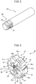
- the shank 20 is composed of, for example, a highly rigid cemented carbide rod-shaped member having a substantially cylindrical shape, and an external thread 24 is formed on the tip thereof.
- the external thread 24 is a tapered thread, the diameter of which decreases in the tip direction of the shank 20.
- the external thread 24 can be a tapered thread having, for example, a pitch of 1 to 2 mm, a thread height of 0.5 to 2 mm, and a taper ratio of 1/50 to 1/20. It is desirable that the maximum outer diameter of the tapered thread be substantially equal to the diameter of the shank 20.
- a coolant pathway for the supply of coolant to the cutting edge can be formed in the shank 20.
- the coolant pathway can include an axial pathway 26 which passes through the shank 20 along the central axis O and radial pathways 28 which pass radially through the shank 20 from the axial pathway 26.
- the head 30 forms the tool body of the T-shaped tool 10 and can be formed from, for example, a steel material.
- a plurality, and in the present embodiment, six, of blades are formed on the head 30.
- the blades are formed by inserts 36, 38 attached to the head 30.
- the inserts 36, 38 can be formed from, for example, cemented carbide, which has high wear resistance.
- the inserts 36, 38 include three upper inserts 36 which protrude on the proximal side of the T-shaped tool 10, i.e., the shank 20 side, and three lower inserts 38 which protrude on the distal side of the T-shaped tool 10, i.e., the side opposite the shank 20.
- a plurality, and in the present embodiment, six, of grooves 32, 34, corresponding to the number of inserts 36, 38, are formed in the head 30.
- the grooves 32, 34 extend from the proximal surface 30a of the head 30 facing the shank 20 to the tip surface 30b facing opposite the shank 20.
- the grooves 32, 34 include first grooves 32 for receiving the upper inserts 36 and second grooves 34 for receiving the lower inserts 38.
- a lower seat 32a for attachment of an upper insert 36 is formed in each first groove 32.
- a lower seat 34a for attachment of a lower insert 38 is formed in each second groove 34.
- the upper inserts 36 and the lower inserts 38 are attached to the upper seats 32a and the lower seats 34a using a suitable bonding technology such as brazing.
- the upper inserts 36 and the lower inserts 38 are formed in the same shape. Though only an upper insert 36 is illustrated in FIGS. 9 to 11 , the lower insert 38 is identical thereto.
- the upper insert 36 has a rake face 36a on the side opposite the upper seat 32a, when attached to the upper seat 32a, and a flank face 36b which faces radially outward.
- a linearly extending main cutting edge 36c and an arc-shaped sub cutting edge 36d, which is connected to the main cutting edge 36c on the upper end of the upper insert 36, are formed by the rake face 36a and the flank face 36b.
- a sub flank face 36e may be formed on the end on which the sub cutting edge 36d is formed.
- the shape and dimensions of the arc-shaped sub cutting edge 36d can be determined in accordance with the size of the fillet R of the machined surface to be machined on the workpiece.
- the upper insert 36 is attached to the upper seat 32a so that the main cutting edge 36c protrudes from the outer peripheral surface of the head 30 and the sub cutting edge 36d protrudes from the proximal surface 30a of the head 30.
- the lower insert 38 is attached to the lower seat 34a so that the main cutting edge 36c protrudes from the outer peripheral surface of the head 30 and the sub cutting edge 36d protrudes from the tip surface 30b of the head 30.
- the upper inserts 36 and the lower inserts 38 are alternatingly arranged at regular intervals in the circumferential direction of the head 30. In order to prevent chatter, the upper inserts 36 and the lower inserts 38 may be alternatingly arranged at irregular intervals in the circumferential direction.
- the upper seat 32a is formed so that the rake face 36a of an attached upper insert 36 is oriented downward. Specifically, when viewed from the tip side of the T-shaped tool 10, the upper insert 36 is inclined with respect to the head 30 so that the rake face of the upper insert 36 can be seen.
- the lower seat 34a is formed so that the rake face of an attached lower insert 38 is oriented upward. Specifically, when viewed from the shank 20 side, the lower insert 38 is inclined with respect to the head 30 so that the rake face of the lower insert 38 can be seen.
- an aperture 40 is formed in a central portion of the head 30.
- the internal thread 50 for engagement with the external thread 24 is formed on the inner circumferential surface of the aperture 40.
- the internal thread 50 is a tapered thread, the diameter of which decreases in the tip direction of the T-shaped tool 10.
- a circumferential groove 48 ( FIG. 8 ) is formed in the inner circumferential surface of the aperture 40. The circumferential groove 48 is arranged so that when the external thread 24 of the shank 20 is engaged with the internal thread of the aperture 40 and the head 30 is connected to the shank 20, the radial passages 28 can open into the circumferential groove 48.
- Branch passages 46a, 46b which pass from the circumferential groove 48 radially through the head 30 and which open in the grooves 32, 34 on the side surface on the side opposite the upper seat 32a and the lower seat 34a, respectively, are formed in the head 30. More specifically, the branch passages 46a, 46b extend in the direction in which coolant is ejected toward the rake faces 36a of the upper insert 36 and the lower insert 38 attached to the upper seat 32a and the lower seat 34a, respectively. By providing coolant from the coolant passage toward the upper insert 36 and the lower insert 38, heat generated by cutting can be reduced, and tool life and swarf discharge are improved.
- the head 30 By engaging the external thread 24 of the shank 20 with the internal thread 50 of the aperture 40 of the head 30, the head 30 is fastened and coupled to the shank 20. At this time, the head 30 is coupled to the shank 20 with a fastening torque that is greater than the maximum torque due to the cutting acting on the head 30 during machining. This is a measure to prevent the tapered threads from being further tightened by the torque based on the cutting, thereby deforming the head 30 and changing the posture of the inserts 36, 38.
- Engagement holes 42 which engage a tightening tool (not illustrated) for imparting the head 30 with the desired fastening torque can be formed in the tip surface 30b of the head 30. Further, a plurality of threaded holes 44 may be formed in the tip surface 30b of the head 30, and screws (not illustrated) may be attached thereto for balancing the rotation of the T-shaped tool 10.
- At least one recess 22 may be formed in the tip of the shank 20, and the shank 20 and the head 30 may be welded at the recess 22 after the head 30 is coupled with the shank 20. Due to the weld, the molten metal of the weld rod is integrated with the steel material of the head 30 and flows into the recess 22. Since shank 20 is composed of cemented carbide, it cannot be welded, but the metal that flows into the recess 22 and solidifies acts as a key, thus forming a detent.
- the shank 20 and the head 30 can be easily separated by loosening the threaded connection while welding the weld part and melting the metal that has flowed into the recess 22. Thereafter, the head 30 can be changed by newly connecting another head 30 to the shank 20 and performing the same welding.
- the T-shaped tool 10 can be finished by grinding so that the main cutting edges and the sub cutting edges of the upper insert 36 and the lower insert 38 have the desired sizes, shapes, and postures.
- the shank 20 does not have a characteristic portion that abuts the proximal surface 30a of the head 20.
- a tensile load is not exerted on the threaded portion (external thread 24) of the shank 20, unlike in the invention of Patent Literature 1.
- cemented carbide which has a high rigidity, can be used for the shank 20, machining speed (cutting speed) can be increased to improve machining efficiency.
- the shank 20 is less likely to become deformed, whereby machining accuracy can be increased.
- material cost and manufacturing cost can be remarkably reduced as compared with a T-shape tool in which the shank and head are cut from a single piece of cemented carbide and are integrally formed in a T-shape. Furthermore, in the present embodiment, it is not necessary to specially produce a reference surface for contacting the shank and the head and a fixation screw, unlike in the invention of Patent Literature 1, whereby manufacturing cost can be reduced.
- the head 30 may be heated to increase the inner diameter of the internal thread 50, and the external thread 24 of the shank 20 may be tightened and then naturally cooled, whereby tapered thread connection may be performed tightly due to the shrink fit effect.
- the heating temperature may be approximately 150 °C, which is sufficiently lower than the temperature at which the inserts 36, 38 are brazed to the tool body 30, which is approximately 700 °C, and the coating temperature of the inserts 36, 38, which is approximately 500 °C, whereby the heating does not adversely affect the brazing or coating.
Landscapes
- Engineering & Computer Science (AREA)
- Mechanical Engineering (AREA)
- Milling Processes (AREA)
Abstract
Description
- The present invention relates to a T-shaped tool such as a T-groove milling cutter, a dovetail milling cutter, or a Christmas tree milling cutter in which a tool body having a cutting edge and a cylindrical shank are connected in an approximately T-shape in a side view, and a method for manufacturing the same.
- T-shaped tools comprising a shank and a head (tool body) connected to the tip of the shank have been conventionally well-known. For example, Patent Literature 1 describes a T-shaped cutter (T-groove milling cutter) in which a cutting head having a cutting edge on the outer periphery thereof is detachably attached to the tip of the shank by means of a screw. The cutting head has an annular projection in the central portion of the side surface facing the shank, and the cutting head and the shank are connected by bringing the end surface of the annular projection into contact with the end surface of the shank, inserting a fixation screw into a head hole formed in the center of the cutting head from the opposite side surface of the cutting head, and engaging the screw with an internal thread formed on the tip of the shank.
- [PTL 1] Japanese Unexamined PCT Application (Kohyo) No.
2013-534189 - In the T-shaped tool described in Patent Literature 1, the shank is tensioned by the fixation screw in a state in which it is in contact with the end surface of the projection of the cutting head. Thus, an axial tensile load is continuously exerted on only one side of each thread of the internal thread of the shank engaged with the fixation screw. Shanks are generally formed from cemented carbide, and cemented carbide has a high compressive strength but a low tensile strength. Thus, in the invention of Patent Literature 1, since the thread lacks rigidity, it is difficult to firmly secure the cutting head to the shank.
- Thus, the present invention aims to solve such problems of the prior art by providing a highly-rigid T-shaped tool which can easily be manufactured and a method for the manufacture thereof.
- In order to achieve the object described above, according to the present invention, there is provided a T-shaped tool comprising a tool body having a cutting edge and a cylindrical shank which are connected in a T-shape in a side view, wherein the shank is composed of cemented carbide and has a tapered external thread, the diameter of which decreases in the tip direction, formed on a tip thereof, the tool body is composed of steel and has a tapered internal thread for engagement with the tapered external thread, and the shank and the tool body are connected by engaging the tapered external thread with the tapered internal thread.
- Furthermore, according to the present invention, there is provided a method for manufacturing a T-shaped tool in which a tool body having a cutting edge and a cylindrical shank are connected in a T-shape in a side view, the method comprising the steps of forming a tapered external thread, the diameter of which decreases in the tip direction, on a tip of the shank, which is composed of cemented carbide, forming a tapered internal thread for engagement with the tapered external thread on the tool body, which is composed of steel, and connecting the shank and the tool body by engaging the tapered external thread with the tapered internal thread.
- According to the present invention, a tool which is approximately T-shaped in a side view is formed by engaging the tapered external thread of the shank with the tapered internal thread of the tool body. Due to the tapered threads, the shank can be tightly engaged with the internal thread of the tool body with a high fastening torque even without, for example, abutting the end face of the shank onto the tool body. Thus, when the tool body is threadedly connected to the shank, a tensile load is not exerted on the tapered external thread of the shank, unlike in the invention of Patent Literature 1, and as the threads are tightened, a compressive load is exerted on each thread of the tapered external thread of the shank, which is composed of cemented carbide, from both sides in the axial direction. Thus, cemented carbide having high rigidity can be used for the shank, and also the rigidity of the connection part between the shank and tool body becomes higher, whereby machining speed (cutting speed) can be increased to improve machining efficiency. Furthermore, by forming the shank from cemented carbide, the shank is less likely to be deformed, whereby machining accuracy can be improved.
-
-
FIG. 1 is a side view of a T-shaped tool according to a preferred embodiment of the present invention. -
FIG. 2 is a plan view of the T-shaped tool ofFIG. 1 as viewed from the shank side. -
FIG. 3 is a bottom view of the T-shaped tool ofFIG. 1 as viewed from the tip side. -
FIG. 4 is a perspective view of the T-shaped tool ofFIG. 1 . -
FIG. 5 is a perspective view of the shank of the T-shaped tool ofFIG. 1 . -
FIG. 6 is a perspective view of the head of the T-shaped tool ofFIG. 1 . -
FIG. 7 is a perspective view of the head as viewed from another direction. -
FIG. 8 is an axial cross-sectional view of the head. -
FIG. 9 is a front view of an upper insert. -
FIG. 10 is a perspective view of the upper insert ofFIG. 9 . -
FIG. 11 is a side view showing an upper end surface of the upper insert ofFIG. 9 . - The preferred embodiments of the present invention will be described below with reference to the attached drawings.
- A T-
shaped tool 10 comprises ashank 20 which is mounted on the tip of a spindle or tool holder of a machine tool and ahead 30 which is coupled to the tip of theshank 20. Theshank 20 is composed of, for example, a highly rigid cemented carbide rod-shaped member having a substantially cylindrical shape, and anexternal thread 24 is formed on the tip thereof. Theexternal thread 24 is a tapered thread, the diameter of which decreases in the tip direction of theshank 20. Theexternal thread 24 can be a tapered thread having, for example, a pitch of 1 to 2 mm, a thread height of 0.5 to 2 mm, and a taper ratio of 1/50 to 1/20. It is desirable that the maximum outer diameter of the tapered thread be substantially equal to the diameter of theshank 20. - A coolant pathway for the supply of coolant to the cutting edge can be formed in the
shank 20. The coolant pathway can include anaxial pathway 26 which passes through theshank 20 along the central axis O andradial pathways 28 which pass radially through theshank 20 from theaxial pathway 26. - The
head 30 forms the tool body of the T-shaped tool 10 and can be formed from, for example, a steel material. A plurality, and in the present embodiment, six, of blades are formed on thehead 30. In the present embodiment, the blades are formed byinserts head 30. Theinserts inserts upper inserts 36 which protrude on the proximal side of the T-shaped tool 10, i.e., theshank 20 side, and threelower inserts 38 which protrude on the distal side of the T-shaped tool 10, i.e., the side opposite theshank 20. - A plurality, and in the present embodiment, six, of
grooves inserts head 30. Thegrooves proximal surface 30a of thehead 30 facing theshank 20 to thetip surface 30b facing opposite theshank 20. Thegrooves first grooves 32 for receiving theupper inserts 36 andsecond grooves 34 for receiving thelower inserts 38. Alower seat 32a for attachment of anupper insert 36 is formed in eachfirst groove 32. Alower seat 34a for attachment of alower insert 38 is formed in eachsecond groove 34. Theupper inserts 36 and thelower inserts 38 are attached to theupper seats 32a and thelower seats 34a using a suitable bonding technology such as brazing. - The
upper inserts 36 and thelower inserts 38 are formed in the same shape. Though only anupper insert 36 is illustrated inFIGS. 9 to 11 , thelower insert 38 is identical thereto. Theupper insert 36 has arake face 36a on the side opposite theupper seat 32a, when attached to theupper seat 32a, and aflank face 36b which faces radially outward. A linearly extendingmain cutting edge 36c and an arc-shapedsub cutting edge 36d, which is connected to themain cutting edge 36c on the upper end of theupper insert 36, are formed by therake face 36a and theflank face 36b. Asub flank face 36e may be formed on the end on which thesub cutting edge 36d is formed. The shape and dimensions of the arc-shapedsub cutting edge 36d can be determined in accordance with the size of the fillet R of the machined surface to be machined on the workpiece. - The
upper insert 36 is attached to theupper seat 32a so that themain cutting edge 36c protrudes from the outer peripheral surface of thehead 30 and thesub cutting edge 36d protrudes from theproximal surface 30a of thehead 30. Likewise, thelower insert 38 is attached to thelower seat 34a so that themain cutting edge 36c protrudes from the outer peripheral surface of thehead 30 and thesub cutting edge 36d protrudes from thetip surface 30b of thehead 30. Furthermore, theupper inserts 36 and thelower inserts 38 are alternatingly arranged at regular intervals in the circumferential direction of thehead 30. In order to prevent chatter, theupper inserts 36 and thelower inserts 38 may be alternatingly arranged at irregular intervals in the circumferential direction. - Referring specifically to
FIGS. 1 and4 , theupper seat 32a is formed so that therake face 36a of an attachedupper insert 36 is oriented downward. Specifically, when viewed from the tip side of the T-shapedtool 10, theupper insert 36 is inclined with respect to thehead 30 so that the rake face of theupper insert 36 can be seen. Likewise, thelower seat 34a is formed so that the rake face of an attachedlower insert 38 is oriented upward. Specifically, when viewed from theshank 20 side, thelower insert 38 is inclined with respect to thehead 30 so that the rake face of thelower insert 38 can be seen. - Further, an
aperture 40 is formed in a central portion of thehead 30. Theinternal thread 50 for engagement with theexternal thread 24 is formed on the inner circumferential surface of theaperture 40. Theinternal thread 50 is a tapered thread, the diameter of which decreases in the tip direction of the T-shapedtool 10. A circumferential groove 48 (FIG. 8 ) is formed in the inner circumferential surface of theaperture 40. Thecircumferential groove 48 is arranged so that when theexternal thread 24 of theshank 20 is engaged with the internal thread of theaperture 40 and thehead 30 is connected to theshank 20, theradial passages 28 can open into thecircumferential groove 48. -
Branch passages circumferential groove 48 radially through thehead 30 and which open in thegrooves upper seat 32a and thelower seat 34a, respectively, are formed in thehead 30. More specifically, thebranch passages upper insert 36 and thelower insert 38 attached to theupper seat 32a and thelower seat 34a, respectively. By providing coolant from the coolant passage toward theupper insert 36 and thelower insert 38, heat generated by cutting can be reduced, and tool life and swarf discharge are improved. - By engaging the
external thread 24 of theshank 20 with theinternal thread 50 of theaperture 40 of thehead 30, thehead 30 is fastened and coupled to theshank 20. At this time, thehead 30 is coupled to theshank 20 with a fastening torque that is greater than the maximum torque due to the cutting acting on thehead 30 during machining. This is a measure to prevent the tapered threads from being further tightened by the torque based on the cutting, thereby deforming thehead 30 and changing the posture of theinserts head 30 with the desired fastening torque can be formed in thetip surface 30b of thehead 30. Further, a plurality of threadedholes 44 may be formed in thetip surface 30b of thehead 30, and screws (not illustrated) may be attached thereto for balancing the rotation of the T-shapedtool 10. - Furthermore, in order to prevent loosening of the connection between the
internal thread 50 of thehead 30 and theexternal thread 24 of theshank 20 due to vibrations or the like that occur during cutting using the T-shapedtool 10, at least onerecess 22 may be formed in the tip of theshank 20, and theshank 20 and thehead 30 may be welded at therecess 22 after thehead 30 is coupled with theshank 20. Due to the weld, the molten metal of the weld rod is integrated with the steel material of thehead 30 and flows into therecess 22. Sinceshank 20 is composed of cemented carbide, it cannot be welded, but the metal that flows into therecess 22 and solidifies acts as a key, thus forming a detent. When loosening the connection between theexternal thread 24 and theinternal thread 50 to separate theshank 20 and thehead 30, theshank 20 and thehead 30 can be easily separated by loosening the threaded connection while welding the weld part and melting the metal that has flowed into therecess 22. Thereafter, thehead 30 can be changed by newly connecting anotherhead 30 to theshank 20 and performing the same welding. - Further, after the
head 30 has been coupled with theshank 20, the T-shapedtool 10 can be finished by grinding so that the main cutting edges and the sub cutting edges of theupper insert 36 and thelower insert 38 have the desired sizes, shapes, and postures. - According to the present embodiment, the
shank 20 does not have a characteristic portion that abuts theproximal surface 30a of thehead 20. Thus, when thehead 30 is threadedly connected to theshank 20, a tensile load is not exerted on the threaded portion (external thread 24) of theshank 20, unlike in the invention of Patent Literature 1. Thus, cemented carbide, which has a high rigidity, can be used for theshank 20, machining speed (cutting speed) can be increased to improve machining efficiency. Furthermore, by forming theshank 20 from cemented carbide (the Young's modulus thereof is about three times greater than that of steel), theshank 20 is less likely to become deformed, whereby machining accuracy can be increased. - According to the present embodiment, material cost and manufacturing cost can be remarkably reduced as compared with a T-shape tool in which the shank and head are cut from a single piece of cemented carbide and are integrally formed in a T-shape. Furthermore, in the present embodiment, it is not necessary to specially produce a reference surface for contacting the shank and the head and a fixation screw, unlike in the invention of Patent Literature 1, whereby manufacturing cost can be reduced.
- Alternatively, instead of tightening the
external thread 24 of theshank 20 and theinternal thread 50 of thehead 30 with a fastening torque which is greater than the maximum torque based on the cutting acting on thehead 30 during machining, thehead 30 may be heated to increase the inner diameter of theinternal thread 50, and theexternal thread 24 of theshank 20 may be tightened and then naturally cooled, whereby tapered thread connection may be performed tightly due to the shrink fit effect. Note that in this case, the heating temperature may be approximately 150 °C, which is sufficiently lower than the temperature at which theinserts tool body 30, which is approximately 700 °C, and the coating temperature of theinserts -
- 10
- T-shaped tool
- 20
- shank
- 24
- external thread
- 30
- head
- 36
- upper insert
- 38
- lower insert
- 50
- internal thread
Claims (6)
- A T-shaped tool in which a tool body having a cutting edge and a cylindrical shank are connected in a T-shape in a side view, wherein
the shank is composed of cemented carbide and has a tapered external thread, the diameter of which decreases in the tip direction, formed on a tip thereof,
the tool body is composed of steel and has a tapered internal thread for engagement with the tapered external thread formed thereon, and
the shank and the tool body are connected by engaging the tapered external thread with the tapered internal thread. - The T-shaped tool according to claim 1, wherein a maximum outer diameter of the tapered external thread is approximately equal to an outer diameter of the shank.
- The T-shaped tool according to claim 1, comprising at least one recess formed in an outer periphery of a tip surface of the shank and a detent which is formed by welding, in a state in which the shank and the tool body are fastened, the tip surface of the tool body in the vicinity of the recess, whereby molten metal flows into the recess.
- A method for manufacturing a T-shaped tool in which a tool body having a cutting edge and a cylindrical shank are connected in a T-shape in a side view, the method comprising the steps of:forming a tapered external thread, the diameter of which decreases in the tip direction, on a tip of the shank, which is composed of cemented carbide,forming a tapered internal thread for engagement with the tapered external thread on the tool body, which is composed of steel, andconnecting the shank and the tool body by engaging the tapered external thread with the tapered internal thread.
- The method for manufacturing a T-shaped tool according to claim 4, wherein the tapered external thread is tightened into the tapered internal thread with a fastening torque that is greater than the maximum torque based on the cutting acting on the tool body during machining.
- The method for manufacturing a T-shaped tool according to claim 4, wherein the tapered external thread is tightened into the tapered internal thread in a state in which the tool body is heated to expand an inner diameter of the internal thread.
Applications Claiming Priority (1)
| Application Number | Priority Date | Filing Date | Title |
|---|---|---|---|
| PCT/JP2017/046215 WO2019123652A1 (en) | 2017-12-22 | 2017-12-22 | T-shaped tool and method for manufacturing t-shaped tool |
Publications (3)
| Publication Number | Publication Date |
|---|---|
| EP3730241A1 true EP3730241A1 (en) | 2020-10-28 |
| EP3730241A4 EP3730241A4 (en) | 2021-08-11 |
| EP3730241B1 EP3730241B1 (en) | 2025-01-22 |
Family
ID=66994051
Family Applications (1)
| Application Number | Title | Priority Date | Filing Date |
|---|---|---|---|
| EP17935377.6A Active EP3730241B1 (en) | 2017-12-22 | 2017-12-22 | T-shaped tool and method for manufacturing t-shaped tool |
Country Status (6)
| Country | Link |
|---|---|
| US (1) | US11478864B2 (en) |
| EP (1) | EP3730241B1 (en) |
| JP (1) | JP6964145B2 (en) |
| CN (1) | CN111511492B (en) |
| CA (1) | CA3086284C (en) |
| WO (1) | WO2019123652A1 (en) |
Families Citing this family (6)
| Publication number | Priority date | Publication date | Assignee | Title |
|---|---|---|---|---|
| JP6714248B1 (en) * | 2019-11-06 | 2020-06-24 | 株式会社ジーベックテクノロジー | Chamfering cutter and chamfering method for work |
| DE102021106246B4 (en) * | 2021-03-15 | 2024-12-19 | Franken GmbH + Co KG Fabrik für Präzisionswerkzeuge | Multi-part, modular tool |
| ES3041305T3 (en) * | 2021-07-02 | 2025-11-11 | Cerin S P A | Tool for milling metal artefacts or hard materials and method for the production thereof |
| IT202100017561A1 (en) * | 2021-07-02 | 2023-01-02 | Cerin S P A | TOOL FOR MILLING METAL PRODUCTS OR HARD MATERIALS AND METHOD FOR ITS PRODUCTION |
| IT202100029990A1 (en) * | 2021-11-26 | 2023-05-26 | Cerin S P A | “TOOL FOR MILLING METAL PRODUCTS OR HARD MATERIALS AND METHOD FOR ITS PRODUCTION” |
| USD1051960S1 (en) * | 2024-04-25 | 2024-11-19 | Dongguan Bosi Hardware Products Co., Ltd. | Pipe reamer |
Family Cites Families (22)
| Publication number | Priority date | Publication date | Assignee | Title |
|---|---|---|---|---|
| SE509218C2 (en) * | 1994-08-29 | 1998-12-21 | Sandvik Ab | shaft Tools |
| JPH10203297A (en) | 1997-01-20 | 1998-08-04 | Daicel Chem Ind Ltd | Gas generator for air bag and air bag device |
| JP3196169B2 (en) * | 1998-12-14 | 2001-08-06 | 株式会社日研工作所 | Integrated shank end mill |
| JP3697371B2 (en) * | 1999-09-07 | 2005-09-21 | 株式会社日研工作所 | End mill chucking structure |
| IL136032A (en) * | 2000-05-09 | 2003-12-10 | Iscar Ltd | Tool joint |
| JP2003251515A (en) * | 2002-02-28 | 2003-09-09 | Mitsubishi Materials Corp | Blade exchangeable cutting tool and blade attached to it |
| SE528251C2 (en) | 2004-09-24 | 2006-10-03 | Seco Tools Ab | Trade for tools and tools with a transition part between a threaded part and a supporting part |
| SE528299C2 (en) * | 2004-09-24 | 2006-10-17 | Seco Tools Ab | Cutting tip and cutting tool with holder part designed as truncated conical thread |
| TWM294377U (en) * | 2006-02-16 | 2006-07-21 | Tian-Ran Wen | Improved milling cutter structure |
| SE531746C2 (en) * | 2007-07-03 | 2009-07-28 | Seco Tools Ab | In several parts tool unit and cutting tool designed |
| IL207624A0 (en) | 2010-08-16 | 2010-12-30 | Iscar Ltd | T-slot cutter |
| JP5488374B2 (en) * | 2010-09-29 | 2014-05-14 | 三菱マテリアル株式会社 | Replaceable head cutting tool |
| JP5455089B2 (en) * | 2012-09-03 | 2014-03-26 | 住友電工ハードメタル株式会社 | Head detachable cutting tool |
| CN203209760U (en) * | 2013-04-28 | 2013-09-25 | 重庆歇马机械曲轴有限公司 | T-shaped milling cutter structure for key slots |
| US9643264B2 (en) * | 2013-07-25 | 2017-05-09 | Kennametal Inc. | Coupling mechanism for cutting tool |
| CN106255564A (en) | 2014-05-08 | 2016-12-21 | 肯纳金属公司 | Coupling mechanism for cutting element |
| EP2944407A1 (en) | 2014-05-16 | 2015-11-18 | Sandvik Intellectual Property AB | A fixation arrangement as well as an interchangeable part and a lock key |
| CN203918062U (en) * | 2014-06-30 | 2014-11-05 | 江苏恒锋工具有限公司 | Combination type T T-slot cutter |
| US20160332241A1 (en) * | 2015-05-14 | 2016-11-17 | Hsiao -Lin Liu | Mill cutter assembly |
| TWI574762B (en) * | 2015-05-20 | 2017-03-21 | Hsin Tien Chang | Tool connection of the thread structure |
| DE202015106360U1 (en) * | 2015-11-20 | 2015-11-27 | Simtek Ag | Milling head unit, milling cutter shank and screw-on milling cutter |
| DE102016105210A1 (en) * | 2016-03-21 | 2017-09-21 | Komet Group Gmbh | Machining tool |
-
2017
- 2017-12-22 JP JP2019559998A patent/JP6964145B2/en active Active
- 2017-12-22 WO PCT/JP2017/046215 patent/WO2019123652A1/en not_active Ceased
- 2017-12-22 CN CN201780097836.XA patent/CN111511492B/en active Active
- 2017-12-22 CA CA3086284A patent/CA3086284C/en active Active
- 2017-12-22 EP EP17935377.6A patent/EP3730241B1/en active Active
- 2017-12-22 US US16/955,295 patent/US11478864B2/en active Active
Also Published As
| Publication number | Publication date |
|---|---|
| CN111511492A (en) | 2020-08-07 |
| EP3730241B1 (en) | 2025-01-22 |
| JPWO2019123652A1 (en) | 2020-10-22 |
| CA3086284A1 (en) | 2019-06-27 |
| JP6964145B2 (en) | 2021-11-10 |
| EP3730241A4 (en) | 2021-08-11 |
| CN111511492B (en) | 2023-08-22 |
| CA3086284C (en) | 2022-05-31 |
| US11478864B2 (en) | 2022-10-25 |
| US20210086275A1 (en) | 2021-03-25 |
| WO2019123652A1 (en) | 2019-06-27 |
Similar Documents
| Publication | Publication Date | Title |
|---|---|---|
| CA3086284C (en) | T-shaped tool and method for manufacturing t-shaped tool | |
| US11872643B2 (en) | T-shaped tool, and method for manufacturing T-shaped tool | |
| EP2213399A1 (en) | Triangular cutting insert and tool holder therefor | |
| KR20120097328A (en) | Milling cutter, especially a round-head milling cutter | |
| US20120093595A1 (en) | Cutting Tool and Cutting Insert for the Same | |
| JP6245564B2 (en) | Cutting tools | |
| KR20150054679A (en) | A gear hobbing tool as well as an insert holder, a chip removal unit, and an insert kit therefor | |
| US7320566B2 (en) | Cutting tool including detachable cutter head | |
| WO2017055156A1 (en) | A tool body, a milling tool and a method for manufacturing a tool body | |
| EP3338930B1 (en) | A ball nose end mill insert, a ball nose end mill tool body and a ball nose end mill | |
| KR20120043736A (en) | Miling tool, in particular a thread milling tool | |
| US20200030894A1 (en) | Drilling Tool Comprising A Replaceable Cutting Disk | |
| US10814408B2 (en) | Replaceable-tip cutting tool main body and replaceable-tip cutting tool | |
| CN217095723U (en) | Tool bit structure and cutter | |
| JP2009291858A (en) | Boring tool | |
| JPH0440822Y2 (en) | ||
| JP2021102236A (en) | Cutter clamp mechanism and manufacturing method of cutter body including cutter clamp mechanism | |
| CN222944571U (en) | A drilling and chamfering compound hole processing tool | |
| EP2719490B1 (en) | Cutting head and cutting tool having a replaceable cutting head | |
| JPH045207Y2 (en) | ||
| CN206839311U (en) | A kind of composite cutting tools | |
| KR20250099130A (en) | Thread milling tools and cutting elements therefor | |
| CZ201747A3 (en) | A cutting tool with replaceable cutting bits |
Legal Events
| Date | Code | Title | Description |
|---|---|---|---|
| STAA | Information on the status of an ep patent application or granted ep patent |
Free format text: STATUS: THE INTERNATIONAL PUBLICATION HAS BEEN MADE |
|
| PUAI | Public reference made under article 153(3) epc to a published international application that has entered the european phase |
Free format text: ORIGINAL CODE: 0009012 |
|
| STAA | Information on the status of an ep patent application or granted ep patent |
Free format text: STATUS: REQUEST FOR EXAMINATION WAS MADE |
|
| 17P | Request for examination filed |
Effective date: 20200618 |
|
| AK | Designated contracting states |
Kind code of ref document: A1 Designated state(s): AL AT BE BG CH CY CZ DE DK EE ES FI FR GB GR HR HU IE IS IT LI LT LU LV MC MK MT NL NO PL PT RO RS SE SI SK SM TR |
|
| AX | Request for extension of the european patent |
Extension state: BA ME |
|
| DAV | Request for validation of the european patent (deleted) | ||
| DAX | Request for extension of the european patent (deleted) | ||
| A4 | Supplementary search report drawn up and despatched |
Effective date: 20210708 |
|
| RIC1 | Information provided on ipc code assigned before grant |
Ipc: B23C 5/12 20060101AFI20210702BHEP Ipc: B23C 5/10 20060101ALI20210702BHEP Ipc: B23B 31/11 20060101ALI20210702BHEP |
|
| GRAP | Despatch of communication of intention to grant a patent |
Free format text: ORIGINAL CODE: EPIDOSNIGR1 |
|
| STAA | Information on the status of an ep patent application or granted ep patent |
Free format text: STATUS: GRANT OF PATENT IS INTENDED |
|
| INTG | Intention to grant announced |
Effective date: 20240917 |
|
| GRAS | Grant fee paid |
Free format text: ORIGINAL CODE: EPIDOSNIGR3 |
|
| P01 | Opt-out of the competence of the unified patent court (upc) registered |
Free format text: CASE NUMBER: APP_60021/2024 Effective date: 20241106 |
|
| GRAA | (expected) grant |
Free format text: ORIGINAL CODE: 0009210 |
|
| STAA | Information on the status of an ep patent application or granted ep patent |
Free format text: STATUS: THE PATENT HAS BEEN GRANTED |
|
| AK | Designated contracting states |
Kind code of ref document: B1 Designated state(s): AL AT BE BG CH CY CZ DE DK EE ES FI FR GB GR HR HU IE IS IT LI LT LU LV MC MK MT NL NO PL PT RO RS SE SI SK SM TR |
|
| REG | Reference to a national code |
Ref country code: GB Ref legal event code: FG4D |
|
| REG | Reference to a national code |
Ref country code: CH Ref legal event code: EP |
|
| REG | Reference to a national code |
Ref country code: IE Ref legal event code: FG4D |
|
| REG | Reference to a national code |
Ref country code: DE Ref legal event code: R096 Ref document number: 602017087501 Country of ref document: DE |
|
| REG | Reference to a national code |
Ref country code: NL Ref legal event code: MP Effective date: 20250122 |
|
| PG25 | Lapsed in a contracting state [announced via postgrant information from national office to epo] |
Ref country code: NL Free format text: LAPSE BECAUSE OF FAILURE TO SUBMIT A TRANSLATION OF THE DESCRIPTION OR TO PAY THE FEE WITHIN THE PRESCRIBED TIME-LIMIT Effective date: 20250122 |
|
| PG25 | Lapsed in a contracting state [announced via postgrant information from national office to epo] |
Ref country code: RS Free format text: LAPSE BECAUSE OF FAILURE TO SUBMIT A TRANSLATION OF THE DESCRIPTION OR TO PAY THE FEE WITHIN THE PRESCRIBED TIME-LIMIT Effective date: 20250422 |
|
| PG25 | Lapsed in a contracting state [announced via postgrant information from national office to epo] |
Ref country code: FI Free format text: LAPSE BECAUSE OF FAILURE TO SUBMIT A TRANSLATION OF THE DESCRIPTION OR TO PAY THE FEE WITHIN THE PRESCRIBED TIME-LIMIT Effective date: 20250122 |
|
| PG25 | Lapsed in a contracting state [announced via postgrant information from national office to epo] |
Ref country code: PL Free format text: LAPSE BECAUSE OF FAILURE TO SUBMIT A TRANSLATION OF THE DESCRIPTION OR TO PAY THE FEE WITHIN THE PRESCRIBED TIME-LIMIT Effective date: 20250122 |
|
| PG25 | Lapsed in a contracting state [announced via postgrant information from national office to epo] |
Ref country code: ES Free format text: LAPSE BECAUSE OF FAILURE TO SUBMIT A TRANSLATION OF THE DESCRIPTION OR TO PAY THE FEE WITHIN THE PRESCRIBED TIME-LIMIT Effective date: 20250122 |
|
| REG | Reference to a national code |
Ref country code: LT Ref legal event code: MG9D |
|
| PG25 | Lapsed in a contracting state [announced via postgrant information from national office to epo] |
Ref country code: NO Free format text: LAPSE BECAUSE OF FAILURE TO SUBMIT A TRANSLATION OF THE DESCRIPTION OR TO PAY THE FEE WITHIN THE PRESCRIBED TIME-LIMIT Effective date: 20250422 Ref country code: IS Free format text: LAPSE BECAUSE OF FAILURE TO SUBMIT A TRANSLATION OF THE DESCRIPTION OR TO PAY THE FEE WITHIN THE PRESCRIBED TIME-LIMIT Effective date: 20250522 |
|
| REG | Reference to a national code |
Ref country code: AT Ref legal event code: MK05 Ref document number: 1761106 Country of ref document: AT Kind code of ref document: T Effective date: 20250122 |
|
| PG25 | Lapsed in a contracting state [announced via postgrant information from national office to epo] |
Ref country code: HR Free format text: LAPSE BECAUSE OF FAILURE TO SUBMIT A TRANSLATION OF THE DESCRIPTION OR TO PAY THE FEE WITHIN THE PRESCRIBED TIME-LIMIT Effective date: 20250122 |
|
| PG25 | Lapsed in a contracting state [announced via postgrant information from national office to epo] |
Ref country code: LV Free format text: LAPSE BECAUSE OF FAILURE TO SUBMIT A TRANSLATION OF THE DESCRIPTION OR TO PAY THE FEE WITHIN THE PRESCRIBED TIME-LIMIT Effective date: 20250122 Ref country code: PT Free format text: LAPSE BECAUSE OF FAILURE TO SUBMIT A TRANSLATION OF THE DESCRIPTION OR TO PAY THE FEE WITHIN THE PRESCRIBED TIME-LIMIT Effective date: 20250522 |
|
| PG25 | Lapsed in a contracting state [announced via postgrant information from national office to epo] |
Ref country code: BG Free format text: LAPSE BECAUSE OF FAILURE TO SUBMIT A TRANSLATION OF THE DESCRIPTION OR TO PAY THE FEE WITHIN THE PRESCRIBED TIME-LIMIT Effective date: 20250122 Ref country code: GR Free format text: LAPSE BECAUSE OF FAILURE TO SUBMIT A TRANSLATION OF THE DESCRIPTION OR TO PAY THE FEE WITHIN THE PRESCRIBED TIME-LIMIT Effective date: 20250423 |
|
| PG25 | Lapsed in a contracting state [announced via postgrant information from national office to epo] |
Ref country code: AT Free format text: LAPSE BECAUSE OF FAILURE TO SUBMIT A TRANSLATION OF THE DESCRIPTION OR TO PAY THE FEE WITHIN THE PRESCRIBED TIME-LIMIT Effective date: 20250122 |
|
| PG25 | Lapsed in a contracting state [announced via postgrant information from national office to epo] |
Ref country code: SE Free format text: LAPSE BECAUSE OF FAILURE TO SUBMIT A TRANSLATION OF THE DESCRIPTION OR TO PAY THE FEE WITHIN THE PRESCRIBED TIME-LIMIT Effective date: 20250122 |
|
| PG25 | Lapsed in a contracting state [announced via postgrant information from national office to epo] |
Ref country code: SM Free format text: LAPSE BECAUSE OF FAILURE TO SUBMIT A TRANSLATION OF THE DESCRIPTION OR TO PAY THE FEE WITHIN THE PRESCRIBED TIME-LIMIT Effective date: 20250122 |
|
| PG25 | Lapsed in a contracting state [announced via postgrant information from national office to epo] |
Ref country code: DK Free format text: LAPSE BECAUSE OF FAILURE TO SUBMIT A TRANSLATION OF THE DESCRIPTION OR TO PAY THE FEE WITHIN THE PRESCRIBED TIME-LIMIT Effective date: 20250122 |
|
| PG25 | Lapsed in a contracting state [announced via postgrant information from national office to epo] |
Ref country code: EE Free format text: LAPSE BECAUSE OF FAILURE TO SUBMIT A TRANSLATION OF THE DESCRIPTION OR TO PAY THE FEE WITHIN THE PRESCRIBED TIME-LIMIT Effective date: 20250122 Ref country code: CZ Free format text: LAPSE BECAUSE OF FAILURE TO SUBMIT A TRANSLATION OF THE DESCRIPTION OR TO PAY THE FEE WITHIN THE PRESCRIBED TIME-LIMIT Effective date: 20250122 |
|
| REG | Reference to a national code |
Ref country code: DE Ref legal event code: R097 Ref document number: 602017087501 Country of ref document: DE |
|
| PG25 | Lapsed in a contracting state [announced via postgrant information from national office to epo] |
Ref country code: RO Free format text: LAPSE BECAUSE OF FAILURE TO SUBMIT A TRANSLATION OF THE DESCRIPTION OR TO PAY THE FEE WITHIN THE PRESCRIBED TIME-LIMIT Effective date: 20250122 |
|
| PG25 | Lapsed in a contracting state [announced via postgrant information from national office to epo] |
Ref country code: SK Free format text: LAPSE BECAUSE OF FAILURE TO SUBMIT A TRANSLATION OF THE DESCRIPTION OR TO PAY THE FEE WITHIN THE PRESCRIBED TIME-LIMIT Effective date: 20250122 |
|
| PLBE | No opposition filed within time limit |
Free format text: ORIGINAL CODE: 0009261 |
|
| STAA | Information on the status of an ep patent application or granted ep patent |
Free format text: STATUS: NO OPPOSITION FILED WITHIN TIME LIMIT |
|
| 26N | No opposition filed |
Effective date: 20251023 |
|
| PGFP | Annual fee paid to national office [announced via postgrant information from national office to epo] |
Ref country code: DE Payment date: 20251028 Year of fee payment: 9 |
|
| PGFP | Annual fee paid to national office [announced via postgrant information from national office to epo] |
Ref country code: GB Payment date: 20251030 Year of fee payment: 9 |
|
| PGFP | Annual fee paid to national office [announced via postgrant information from national office to epo] |
Ref country code: IT Payment date: 20251121 Year of fee payment: 9 |
|
| PGFP | Annual fee paid to national office [announced via postgrant information from national office to epo] |
Ref country code: FR Payment date: 20251110 Year of fee payment: 9 |