EP3729953A1 - Schneidvorrichtung - Google Patents
Schneidvorrichtung Download PDFInfo
- Publication number
- EP3729953A1 EP3729953A1 EP20000118.8A EP20000118A EP3729953A1 EP 3729953 A1 EP3729953 A1 EP 3729953A1 EP 20000118 A EP20000118 A EP 20000118A EP 3729953 A1 EP3729953 A1 EP 3729953A1
- Authority
- EP
- European Patent Office
- Prior art keywords
- cutting
- switching
- shaft
- adjusting
- coupling
- Prior art date
- Legal status (The legal status is an assumption and is not a legal conclusion. Google has not performed a legal analysis and makes no representation as to the accuracy of the status listed.)
- Granted
Links
Images



Classifications
-
- B—PERFORMING OPERATIONS; TRANSPORTING
- B26—HAND CUTTING TOOLS; CUTTING; SEVERING
- B26D—CUTTING; DETAILS COMMON TO MACHINES FOR PERFORATING, PUNCHING, CUTTING-OUT, STAMPING-OUT OR SEVERING
- B26D5/00—Arrangements for operating and controlling machines or devices for cutting, cutting-out, stamping-out, punching, perforating, or severing by means other than cutting
-
- A—HUMAN NECESSITIES
- A01—AGRICULTURE; FORESTRY; ANIMAL HUSBANDRY; HUNTING; TRAPPING; FISHING
- A01D—HARVESTING; MOWING
- A01D90/00—Vehicles for carrying harvested crops with means for selfloading or unloading
- A01D90/02—Loading means
- A01D90/04—Loading means with additional cutting means
- A01D90/06—Loading means with additional cutting means with chaff cutters, i.e. choppers used as loading and cutting means
-
- A—HUMAN NECESSITIES
- A01—AGRICULTURE; FORESTRY; ANIMAL HUSBANDRY; HUNTING; TRAPPING; FISHING
- A01F—PROCESSING OF HARVESTED PRODUCE; HAY OR STRAW PRESSES; DEVICES FOR STORING AGRICULTURAL OR HORTICULTURAL PRODUCE
- A01F15/00—Baling presses for straw, hay or the like
- A01F15/08—Details
- A01F15/10—Feeding devices for the crop material e.g. precompression devices
-
- B—PERFORMING OPERATIONS; TRANSPORTING
- B26—HAND CUTTING TOOLS; CUTTING; SEVERING
- B26D—CUTTING; DETAILS COMMON TO MACHINES FOR PERFORATING, PUNCHING, CUTTING-OUT, STAMPING-OUT OR SEVERING
- B26D5/00—Arrangements for operating and controlling machines or devices for cutting, cutting-out, stamping-out, punching, perforating, or severing by means other than cutting
- B26D5/02—Means for moving the cutting member into its operative position for cutting
-
- A—HUMAN NECESSITIES
- A01—AGRICULTURE; FORESTRY; ANIMAL HUSBANDRY; HUNTING; TRAPPING; FISHING
- A01F—PROCESSING OF HARVESTED PRODUCE; HAY OR STRAW PRESSES; DEVICES FOR STORING AGRICULTURAL OR HORTICULTURAL PRODUCE
- A01F15/00—Baling presses for straw, hay or the like
- A01F15/08—Details
- A01F15/10—Feeding devices for the crop material e.g. precompression devices
- A01F2015/107—Means for withdrawing knives, rotor or walls of the feeding chamber in case of plugging or congestion
-
- A—HUMAN NECESSITIES
- A01—AGRICULTURE; FORESTRY; ANIMAL HUSBANDRY; HUNTING; TRAPPING; FISHING
- A01F—PROCESSING OF HARVESTED PRODUCE; HAY OR STRAW PRESSES; DEVICES FOR STORING AGRICULTURAL OR HORTICULTURAL PRODUCE
- A01F15/00—Baling presses for straw, hay or the like
- A01F15/08—Details
- A01F15/10—Feeding devices for the crop material e.g. precompression devices
- A01F2015/108—Cutting devices comprising cutter and counter-cutter
Definitions
- the invention relates to a cutting device for conveying and cutting in particular agricultural material.
- the cutting device has a conveying channel and at least one pivotably mounted cutting element.
- the cutting element can be moved from a rest position into a cutting position by moving it in a first pivoting direction. In the cutting position, the cutting element for cutting the material to be cut is at least partially positioned within the conveying channel.
- the cutting device has an actuating device which comprises an actuating element which, at least in the cutting position of the cutting element, rests on the cutting element and is in particular pivotably mounted about an actuating pivot axis.
- the cutting device has a shift shaft which can be converted into different shift positions and is rotatably mounted about a shift shaft axis. With the Shift shaft, the actuating element is coupled in at least one of the shift positions of the shift shaft.
- the cutting device has a return element for returning the cutting element into the cutting position and for holding the cutting element in the cutting position.
- an agricultural harvesting machine is known with a cutting device as described above. Due to the possibility of transferring the cutting element from the rest position into the cutting position, a cut length of the material to be cut can be set.
- the selector shaft can be used to select whether the cutting element should be positioned in the rest or in the cutting position during operation or which cutting elements of a plurality of cutting elements should be positioned in the rest or in the cutting position during operation.
- the object of the present invention is to provide a cutting device of the generic type with a smaller space requirement and the greatest possible operational reliability.
- the object is achieved in that the actuating element has a switching contact area which, in one switching position, rests against the switching shaft during operation.
- the actuating element is coupled therewith by being in direct contact with the switching shaft.
- the conveyor channel of the cutting device is in particular delimited by a conveyor channel wall.
- the conveying channel wall has, in particular, slot-shaped recesses through which the cutting element extends in particular at least in the cutting position.
- the conveyor channel is in particular delimited by a conveyor and cutting rotor.
- the cutting element In the rest position, the cutting element is not or only to a small extent arranged within the conveying channel. In contrast, in the cutting position of the cutting element, a larger proportion, in particular a cutting edge of the cutting element, is arranged in the conveying channel.
- the cutting element is preferably pivoted upwards from the rest position into the operating position.
- the switching shaft can be used, in particular, to set the position in which the cutting element is to be in the subsequent operation between two operating phases. In each of its possible switching positions, the switching shaft defines whether the cutting element should be in the cutting position or in the rest position.
- the switching shaft is designed such that the adjusting element rests on the switching shaft either in the cutting position or in the rest position when the cutting device is in operation.
- the selector shaft has, in particular, different geometries along its circumference, through which the position of the cutting element is ultimately predefined.
- the actuating element is designed both to rest against the cutting element and to rest against the selector shaft, there are further components for power transmission between the selector shaft and the actuating element is no longer necessary. As a result, the installation space of the cutting device is minimized and the number of components necessary for its functioning is reduced to a minimum. This can significantly reduce downtime of the cutting device.
- the switching shaft axis runs in particular transversely to the conveying direction of the crop in the conveying channel.
- the selector shaft is designed in particular to adjust a plurality of adjusting elements and thus cutting elements.
- the selector shaft preferably has a selector shaft main body extending in the direction of the selector shaft axis as well as a plurality of selector shaft attachments adjoining one another in the direction of the selector shaft axis, which are designed at least in one switch position to rest on the switch contact area of the actuating element.
- the switching contact area preferably has a recess into which a switching element of the switching shaft extends in the switching position during operation.
- the switching element is in particular a cam, preferably comprised by a switching shaft attachment, which extends radially away from the switching shaft axis.
- the actuating element preferably has at least one pin which, in the switching position, extends into a recess in the switching shaft during operation. The pairing of recess and switching element / pin enables reliable engagement of the switching shaft and actuating element in one another in the switching position and thus preventing the switching position from being left unintentionally.
- the resetting element presses in particular the actuating element against the switching shaft, in particular against the switching element.
- the actuating element is preferably released by transferring the coupling element into the coupling position both from the switching shaft and from the cutting element.
- the coupling element counteracts the restoring element with regard to the pivoting direction of the adjusting element.
- the restoring element ensures, in particular after the coupling element has been transferred back from the coupling position, that the adjusting element is in contact with the cutting element and / or the switching shaft.
- the coupling element is preferably mounted so as to be pivotable, in particular, about the stationary adjusting pivot axis.
- the coupling function can be implemented particularly reliably due to the type of storage. Because the adjusting element and the coupling element are arranged pivotably about the same axis, the cutting device is also particularly compact and when the coupling element is moved into the coupling position, friction between the coupling and adjusting element is avoided.
- the adjusting device is designed in such a way that the cutting element is arranged in the rest position during operation and when the switching contact area is in contact with the switching shaft.
- the adjusting element rests either on the cutting element or on the selector shaft during operation. This avoids extreme component loads that were associated with simultaneous contact with both the cutting element and the selector shaft.
- the cutting device preferably has a drive device for continuous rotation of the selector shaft by more than 360 °.
- the drive device has a hydraulic motor, an electric motor or a pneumatically operated motor.
- the drive device enables uninterrupted rotation at, in particular, a constant rotational speed, with no manual force having to be introduced by an operator.
- the drive device is designed for continuous, multiple and uninterrupted rotation of the selector shaft. It is also possible to start the rotation quickly and then slow it down and vice versa. In addition to its switching function, a cleaning function can be achieved by the switching shaft through the drive device.
- the drive device comprises an angle sensor. This allows the drive device to automatically move to any preselected switching positions without having to interrupt the continuous rotation.
- the drive device is particularly preferably designed to provide a switching shaft rotation speed in a range from 10 to 80 revolutions per minute. Due to these rotational speeds of the switching shaft, agricultural cuttings deposits such as hay or straw deposits can be conveyed out in a particularly effective manner and this enables optimal protection of the cutting device components in this area of activity.
- the drive device preferably has a transmission for reducing a drive speed that deviates from a shift shaft speed, in particular of the hydraulic motor or an alternative electric motor.
- the transmission comprises a spur gear pairing, by means of which the drive speed with its transmission to the shift shaft is reduced to the shift shaft speed.
- the transmission enables drive motors with sufficient drive power to be used, the installation space of which is small due to a large speed-torque ratio.
- a radial extension of the shift element from the shift shaft axis is preferably at least 1.3 times, in particular at least 1.5 times as large as the radial extension of an at least substantially cylindrical section of the shift shaft from the shift shaft axis.
- the shift shaft has a plurality of shift elements which are spaced from one another in the direction of the shift shaft axis and are each assigned to a cutting element.
- the essentially cylindrical section of the shift shaft is located between two of these shift shaft elements. Due to the significantly larger radius of the switching elements compared to this section, they achieve a particularly large conveying function and thus ensure quick cleaning of the cutting device.
- the cutting device has at least one cleaning element which is coupled to the shift shaft and rotates as a function of its rotation and whose cleaning axis of rotation is arranged in particular parallel to the shift shaft axis.
- the cleaning element is coupled to the selector shaft in particular via a pair of spur gears and is preferred also driven by the drive device.
- the separate cleaning element can also automatically clean areas of the cutting device that are further apart from the selector shaft.
- the object is also achieved by an agricultural machine with a cutting device according to one of the preceding claims.
- the agricultural machine is preferably a baling press or a loading wagon, by means of which hay or straw in particular can be picked up and cut directly from the ground during operation.
- the Figs. 1 to 3 show a cutting device 2 according to the invention in a longitudinal section.
- the cutting device 2 forms a conveying channel 4 through which in particular agricultural material to be cut is conveyed and in particular cut during operation.
- the conveying channel 4 is delimited by a conveying and cutting rotor 54 on the one hand and a conveying channel wall 56 on the other hand.
- the cutting device 2 has a plurality of pivotably mounted cutting elements 6 (see also Fig. 4 ), of which in the Figs. 1 to 3 each one is shown.
- the cutting element 6 is moved in a first pivoting direction 8 from a rest position (cf. Fig. 3 ) into a cutting position (cf. Fig. 1 ) transferable. In the cutting position, the cutting element 6 is positioned in the conveying channel 4 for cutting the material to be cut with a cutting edge.
- the cutting device 2 has an adjusting device (I) for returning the cutting element 6 into the cutting position and for holding the cutting element 6 in the cutting position.
- the adjusting device (I) comprises an adjusting element 22 and a restoring element 10.
- the adjusting element 22 is mounted pivotably about an adjusting pivot axis 36.
- the restoring element 10 is fixedly arranged at one end on a machine frame and at the other end on a second leg 44 of the adjusting element 22.
- the adjusting element 22 rests with a roller on a first surface section 18 of the cutting element 6.
- a tensile force of the restoring element 10 pulls the adjusting element 22 into a recess in the cutting element 6, whereby the cutting element 6 remains in the cutting position as far as possible during operation.
- the adjusting element 22 is moved from its in Fig. 3 position shown applied to the first surface section 18.
- a first torque is applied to the cutting element 6 in the pivoting direction 8.
- the cutting element can be released regularly from the rest position and slides upwards and along the adjusting element 22. Due to the convergence of the second leg 44 of the adjusting element 22 to the pivot axis of the cutting element 6 and the associated shortening of the restoring element 10, the torque applied to the cutting element 6 decreases with the upward pivoting of the cutting element 6, starting from the first torque.
- the adjusting device (I) enables the cutting element 6 to pivot back from the cutting position against the tensile force of the restoring element 10. After the foreign body has passed, the restoring element 10 causes the cutting element to be reset 6 in the cutting position.
- a coupling element 26 and the switching shaft 28 serve to transfer the cutting element 6 from the cutting position to the rest position.
- the coupling element 26, like the actuating element 22, is mounted pivotably about the actuating pivot axis 36. To enable the cutting element 6 to pivot back into the rest position as a result of gravity, the coupling element 26 can first be pivoted against a coupling contact area 40 of the actuating element 22 (cf. Fig. 2 ). This pivoting is possible in particular with a hydraulic cylinder 24 coupled to the coupling element (cf. Fig. 5 ) bring about.
- the coupling contact area 40 is arranged on a first leg 34 of the actuating element 22.
- the coupling position shown is the adjusting element 22 both of the cutting element 6 and of the shift shaft 28 spaced apart.
- the shift shaft 28 is rotatably mounted about a shift shaft axis 58 and comprises several shift elements 38 along its circumference.
- the shift shaft 28 is shown in FIG Fig. 1 a first switching position for positioning the cutting element 6 in the cutting position.
- the switching shaft 28 is pivoted through ⁇ 360 ° into further switching positions, such as in FIG Fig. 2 transferable.
- a switching element 38 for positioning the cutting element 6 in the rest position faces the switching contact area 32, contrary to the first switching positions.
- the coupling element 26 can be moved out of the coupling position (cf. Fig. 2 ) into a release position (cf. Fig. 3 ) transfer back from a coupling reset element 42.
- the actuating element 22 follows the movement of the coupling element 26 until the actuating element 22 rests with a switching contact area on one of the switching elements 38 of the switching shaft 28.
- the switching contact area 32 is arranged on the first leg 34 of the actuating element 22.
- the switch contact area 32 has a recess into which the one switch element 38 partially extends in the further switch position and after the coupling element 26 has been released (cf. Fig. 3 ). This avoids contact between the cutting element 6 and the actuating element 22, as a result of which the cutting element 6 remains in the rest position.
- a transfer of the switching shaft 28 from the further switching position to a first switching position can be brought about in an analogous manner.
- a second adjusting element 16 of a second adjusting device (II) is rigidly connected to the coupling element 26.
- the second adjusting element 16 like the coupling element 26, can thus be pivoted about the adjusting pivot axis 36.
- the second setting element 16 is to be brought into contact with a second surface section 20 of the cutting element 6.
- the second adjusting element 16 is used to pivot the cutting element 6 from the rest position into the first pivoting direction 8.
- the second adjusting element 16 is designed to apply a second torque to the cutting element 6 in the rest position, the second torque being greater than that of the adjusting device (I) first torque to be applied to the cutting element 6 in the rest position.
- the second torque is so great that the cutting element 6 can be reliably pivoted from the rest position into the first pivoting direction 8 even if there are deposits of material to be cut between the cutting element 6 and the conveying channel wall 56, if such pivoting can no longer be achieved due to the smaller first torque is.
- the second setting element 16 extends below a plurality of cutting elements 6 (cf. Fig. 5 ). Each cutting element 6 is assigned an adjusting device (I), each with an adjusting element 22.
- the coupling element 26, like the second actuating element 16, has a width which essentially corresponds to a width of the conveying channel 4, whereby all actuating elements 22 can be released by the coupling element 26 both from the respective cutting element 6 and from the switching shaft 28.
- the cutting device 2 has a drive device having a hydraulic motor 46 for continuous rotation of the selector shaft 28 by more than 360 ° (cf. Fig. 4 and 5 ).
- the cutting device 2 has a locking device, not shown, for locking the drive device when the switching contact area 32 is in contact with the switching shaft 28, in particular when the coupling element 26 is not arranged in the coupling position.
- the hydraulic motor 46 is coupled to the selector shaft 28 via a gear (not shown) for reducing its drive speed.
- the drive device for the automatic setting of different switching positions of the switching shaft 28 is designed by an angle sensor.
- the shift elements 38 of the shift shaft 28 have a radial extension from the shift shaft axis 58 which is more than 1.3 times as large as the radial extension of a cylindrical section 50 of the shift shaft 28 from the shift shaft axis 58 (cf. Fig. 6 ). Between two adjacent shift elements 38 in the direction of the shift shaft axis 58, the shift shaft 28 has, in particular, a conveying element 52.
- Fig. 6 shows exemplary conveying elements 52 only on a section of the switching shaft 28. Such conveying elements 52 are preferably arranged along the entire switching shaft length on the switching shaft 28.
- Fig. 7 shows a baling press 30 with a cutting device 2 according to the invention.
- the baling press 30 is moved in a direction of travel 60 and in the process agricultural cuttings such as hay or straw picked up from the ground and conveyed, among other things, by the conveying and cutting rotor 54 through the conveying channel 4. Among other things, it is cut by the cutting element shown in the cutting position and then fed to a bale chamber to form a round bale.
Landscapes
- Life Sciences & Earth Sciences (AREA)
- Forests & Forestry (AREA)
- Engineering & Computer Science (AREA)
- Mechanical Engineering (AREA)
- Environmental Sciences (AREA)
- Threshing Machine Elements (AREA)
- Harvester Elements (AREA)
Abstract
Description
- Die Erfindung betrifft eine Schneidvorrichtung zum Fördern und Schneiden insbesondere landwirtschaftlichen Schneidgutes. Die Schneidvorrichtung hat einen Förderkanal und zumindest ein schwenkbar gelagertes Schneidelement. Das Schneidelement ist durch eine Bewegung in eine erste Schwenkrichtung aus einer Ruhestellung in eine Schneidstellung überführbar. In der Schneidstellung ist das Schneidelement zum Schneiden des Schneidgutes zumindest teilweise innerhalb des Förderkanals positioniert. Die Schneidvorrichtung hat eine Stellvorrichtung, die ein zumindest in der Schneidstellung des Schneidelementes im Betrieb am Schneidelement anliegendes und insbesondere schwenkbar um eine Stellschwenkachse gelagertes Stellelement umfasst. Die Schneidvorrichtung hat eine in unterschiedliche Schaltstellungen überführbare, drehbar um eine Schaltwellenachse gelagerte Schaltwelle. Mit der Schaltwelle ist das Stellelement in zumindest einer der Schaltstellungen der Schaltwelle gekoppelt. Die Schneidvorrichtung hat ein Rückstellelement zum Rückführen des Schneidelementes in die Schneidstellung und zum Halten des Schneidelementes in der Schneidstellung.
- Aus der
DE 20 2014 006 083 U1 ist eine landwirtschaftliche Erntemaschine bekannt mit einer vorbeschriebenen Schneidvorrichtung. Durch die Möglichkeit der Überführung des Schneidelementes von der Ruhestellung in die Schneidstellung lässt sich eine Schnittlänge des Schneidgutes einstellen. Durch die Schaltwelle lässt sich auswählen, ob das Schneidelement im Betrieb in der Ruhe- oder in der Schneidstellung bzw. welche Schneidelemente einer Mehrzahl von Schneidelementen im Betrieb in der Ruhe- oder in der Schneidstellung positioniert sein sollen. - Aufgabe der vorliegenden Erfindung ist es, eine gattungsgemäße Schneidvorrichtung mit einem geringeren Bauraumbedarf bei größtmöglicher Betriebszuverlässigkeit bereitzustellen.
- Erfindungsgemäß wird die Aufgabe dadurch gelöst, dass das Stellelement einen in der einen Schaltstellung im Betrieb an der Schaltwelle anliegenden Schaltkontaktbereich hat. Somit ist das Stellelement zumindest in der einen Schaltstellung der Schaltwelle durch unmittelbares Anliegen an der Schaltwelle damit gekoppelt.
- Der Förderkanal der Schneidvorrichtung wird insbesondere von einer Förderkanalwandung begrenzt. Die Förderkanalwandung hat insbesondere schlitzförmige Ausnehmungen, durch die sich das Schneidelement zumindest in der Schneidstellung insbesondere hindurcherstreckt. Gegenüber der Förderkanalwandung ist der Förderkanal insbesondere begrenzt durch einen Förder- und Schneidrotor. Im Betrieb der Schneidvorrichtung und bei Positionierung des Schneidelementes in der Schneidstellung befindet sich das Schneidelement bei Betrachtung in Förderrichtung des Schneidgutes wiederkehrend zwischen zwei rotierenden und zum Schneidelement benachbarten Mitnehmern des Förder- und Schneidrotors.
- In der Ruhestellung ist das Schneidelement nicht oder nur zu einem geringen Teil innerhalb des Förderkanals angeordnet. In der Schneidstellung des Schneidelementes ist demgegenüber ein größerer Anteil, insbesondere eine Schneide des Schneidelementes, im Förderkanal angeordnet. Bevorzugt wird das Schneidelement aus der Ruhestellung in die Betriebsstellung aufwärts verschwenkt.
- In der Schneidstellung des Schneidelementes wirkt das zumindest im Betrieb am Schneidelement anliegende Stellelement mit einer Kraft auf das Schneidelement ein. Diese Kraft wird zumindest teilweise durch das Rückstellelement, was insbesondere unmittelbar am Stellelement angeordnet ist, bereitgestellt. Durch die Kraft wird das Schneidelement zum einen in die Schneidstellung geführt und zum anderen darin gehalten.
- Die Kraft zum Halten des Schneidelementes in der Schneidstellung ist im Betrieb so groß, dass ein zuverlässiges Schneiden des durch den Förderkanal bewegten Schneidgutes möglich ist. Gleichzeitig ist die Kraft so gering, dass bei einem Fremdkörper wie einem Stein im Schneidgut das Schneidelement vor dem Fremdkörper ausweichen, d.h. entgegen die durch das Stellelement aufgebrachten Kraft zurückschwenken kann. Hat der Fremdkörper daraufhin den Förderkanal durchtreten, wird das Schneidelement durch die Stellvorrichtung und das Rückstellelement in die Schneidstellung zurückgeführt.
- Durch die Schaltwelle lässt sich insbesondere zwischen zwei Betriebsphasen einstellen, in welcher Stellung sich das Schneidelement im folgenden Betrieb befinden soll. In jeder seiner möglichen Schaltstellungen definiert die Schaltwelle, ob sich das Schneidelement in der Schneidstellung oder in der Ruhestellung befinden soll. Insbesondere ist die Schaltwelle so ausgebildet, dass das Stellelement im Betrieb der Schneidvorrichtung entweder in der Schneidstellung oder in der Ruhestellung an der Schaltwelle anliegt. Dazu hat die Schaltwelle entlang ihres Umfangs insbesondere unterschiedliche Geometrien, durch welche letztlich die Stellung des Schneidelementes vordefiniert wird.
- Im Betrieb befindet sich die Schneidvorrichtung dann, wenn Schneidgut durch den Förderkanal gefördert und ggf. durch das Schneidelement geschnitten wird.
- Indem das Stellelement sowohl zum Anliegen am Schneidelement als auch zum Anliegen an der Schaltwelle ausgebildet ist, sind weitere Bauteile zur Kraftübertragung zwischen der Schaltwelle und dem Stellelement nicht weiter notwendig. Dadurch ist sowohl der Bauraum der Schneidvorrichtung minimiert als auch die Anzahl von zur Funktion derer notwendigen Bauteilen auf ein Minimum reduziert. Dadurch können Ausfallzeiten der Schneidvorrichtung deutlich reduziert werden.
- Die Schaltwellenachse verläuft insbesondere quer zur Förderrichtung des Erntegutes im Förderkanal. Die Schaltwelle ist insbesondere zur Einstellung einer Mehrzahl von Stellelementen und damit Schneidelementen ausgebildet. Bevorzugt hat die Schaltwelle einen in Richtung der Schaltwellenachse durchgehenden Schaltwellengrundkörper sowie eine Mehrzahl von in Richtung der Schaltwellenachse aneinander anschließende Schaltwellenaufsätze, die zumindest in der einen Schaltstellung zur Anlage an dem Schaltkontaktbereich des Stellelementes ausgebildet sind.
- Bevorzugt ist das Stellelement schwenkbar um die Stellschwenkachse gelagert. Besonders bevorzugt ist der Schaltkontaktbereich von einem ersten Schenkel des Stellelementes umfasst. Der erste Schenkel erstreckt sich im Betrieb in der Schneidstellung des Schneidelementes von der Stellschwenkachse aus vom Schneidelement weg. Insbesondere besteht das Stellelement aus zwei zueinander starren Schenkeln, die sich jeweils im Wesentlichen radial von der Stellschwenkachse weg erstrecken. Durch die Anordnung des Schaltkontaktbereichs am vom Schneidelement abgewandten Schenkel lässt sich die Stellvorrichtung trotz der Mehrfachfunktion des Stellelementes einfach aufbauen und Bauteilkollisionen vermeiden. Insbesondere kann eine größere radiale Erstreckung des Stellelementes von der Stellschwenkachse, welche mit der Anordnung des Schaltkontaktbereiches an dem dem Schneidelement zugewandten Schenkel notwendigerweise einherginge, vermieden werden.
- Vorzugsweise weist der Schaltkontaktbereich eine Vertiefung auf, in die sich in der Schaltstellung im Betrieb ein Schaltelement der Schaltwelle erstreckt. Das Schaltelement ist insbesondere eine, bevorzugt von einem Schaltwellenaufsatz umfasste, Nocke, die sich von der Schaltwellenachse radial weg erstreckt. Alternativ hat bevorzugt das Stellelement zumindest einen Zapfen, der sich in der Schaltstellung im Betrieb in eine Vertiefung der Schaltwelle erstreckt. Durch die Paarung aus Vertiefung und Schaltelement/Zapfen lässt sich in der Schaltstellung ein zuverlässiges Eingreifen von Schaltwelle und Stellelement ineinander erreichen und so ein unbeabsichtigtes Verlassen der Schaltstellung vermeiden. Das Rückstellelement drückt im Betrieb in der Schaltstellung insbesondere das Stellelement gegen die Schaltwelle, insbesondere gegen das Schaltelement.
- In einer vorteilhaften Ausgestaltung der Erfindung hat die Schneidvorrichtung ein Kuppelelement, das zum Lösen des Stellelementes von der Schaltwelle ausgebildet ist. Insbesondere liegt das Kuppelelement in einer Kuppelstellung an einem Kuppelkontaktbereich des Stellelementes an. Das Kuppelelement sorgt dafür, dass zu einer Überführung der Schaltwelle in eine andere Schaltstellung im Wesentlichen kein Drehmoment überwunden werden muss, das aus einem Anliegen des Stellelementes an der Schaltwelle resultierte. Stattdessen beabstandet das Kuppelelement das Stellelement vom Schaltelement, bevor die Schaltwelle in eine andere Schaltstellung überführt wird. Dadurch kommt es zu geringeren Bauteilbelastungen und dadurch zu geringeren Ausfallzeiten.
- Das Kuppelelement ist insbesondere schwenkbar gelagert. Mit seiner Überführung in die Kuppelstellung legt es sich bevorzugt an den Kuppelkontaktbereich des Stellelementes an. Der Kuppelkontaktbereich ist besonders bevorzugt weiter von der Stellschwenkachse beabstandet als der Schaltkontaktbereich. Der Kuppelkontaktbereich ist vorzugsweise Teil des ersten Schenkels des Stellelementes. Durch diesen Aufbau lässt sich ein Lösen des Stellelementes von der Schaltwelle schon mit einer verhältnismäßig geringen Kraft zuverlässig erreichen und kann das Kuppelelement entsprechend klein bauen. Außerdem kann der Abstand zwischen dem Schneidelement und der Stellschwenkachse gering gehalten werden.
- Bevorzugt wird das Stellelement durch ein Überführen des Kuppelelementes in die Kuppelstellung sowohl von der Schaltwelle als auch vom Schneidelement gelöst. Insbesondere wirkt das Kuppelelement hinsichtlich der Schwenkrichtung des Stellelementes dem Rückstellelement entgegen. Das Rückstellelement stellt insbesondere nach Rücküberführung des Kuppelelementes aus der Kuppelstellung ein Anliegen des Stellelementes am Schneidelement und/oder an der Schaltwelle sicher.
- Vorzugsweise ist das Kuppelelement insbesondere um die ortsfeste Stellschwenkachse schwenkbar gelagert. Durch die Art der Lagerung kann die Kuppelfunktion besonders zuverlässig realisiert werden. Dadurch, dass das Stellelement und das Kuppelelement um die gleiche Achse schwenkbar angeordnet sind, baut die Schneidvorrichtung außerdem besonders kompakt und wird bei einer Überführung des Kuppelelementes in die Kuppelstellung eine Reibung zwischen Kuppel- und Stellelement vermieden.
- Bevorzugt ist am Kuppelelement ein das Kuppelelement aus der Kuppelstellung rückführendes Kuppelrückstellelement angeordnet. Das Kuppelrückstellelement ist insbesondere als Zugfeder ausgebildet. Besonders bevorzugt ist am Kuppelelement ein einfach wirkender Hydraulikzylinder angeordnet, durch den das Kuppelelement bevorzugt in die Kuppelstellung überführbar ist. Durch das Kuppelrückstellelement wird die Rückführung aus der Kuppelstellung auf mechanisch besonders einfache Weise zuverlässig realisiert. Außerdem erübrigt sich dadurch ein weiterer bzw. komplexer aufgebauter Hydraulikzylinder.
- Vorzugsweise ist das Rückstellelement an einem zweiten Schenkel des Stellelementes angeordnet. Der zweite Schenkel erstreckt sich in der Schneidstellung des Schneidelementes von der Stellschwenkachse zum Schneidelement. Das Rückstellelement ist insbesondere als Zugfeder ausgebildet. Ein Ende des Rückstellelementes ist bevorzugt ortsfest am Maschinenrahmen angeordnet. Insbesondere erstreckt sich das Rückstellelement zumindest in der Schneidstellung des Schneidelementes und in einer Seitenansicht bzw. in einem Längsschnitt der Schneidvorrichtung betrachtet zumindest teilweise hinter dem Schneidelement. Dadurch ist das Rückstellelement besonders platzsparend angeordnet. Die Rückstellkraft wirkt zumindest im Wesentlichen in radialer Richtung auf das Stellelement. Durch die Anordnung des Rückstellelementes am zweiten Schenkel wird die Rückstellkraft des Rückstellelementes in den Bereich in das Stellelement eingeleitet, mit dem das Stellelement auch an dem Schneidelement anliegt. Insofern kommt es zu einer besonders unmittelbaren Kraftübertragung auf das Schneidelement und der Belastung nur eines geringen Teils des Stellelementes, was dessen Ausfallwahrscheinlichkeit reduziert.
- In einer vorteilhaften Ausgestaltung der Erfindung ist die Stellvorrichtung derart ausgebildet, dass das Schneidelement im Betrieb und bei Anliegen des Schaltkontaktbereichs an der Schaltwelle in der Ruhestellung angeordnet ist. Dadurch liegt das Stellelement im Betrieb entweder am Schneidelement oder an der Schaltwelle an. Dadurch werden extreme Bauteilbelastungen vermieden, die mit einem gleichzeitigen Anliegen sowohl am Schneidelement als auch an der Schaltwelle einhergingen.
- Vorzugsweise hat die Schneidvorrichtung eine Antriebsvorrichtung zu einer kontinuierlichen Rotation der Schaltwelle um mehr als 360°. Insbesondere weist die Antriebsvorrichtung einen Hydraulikmotor, einen Elektromotor oder einen pneumatisch arbeitenden Motor auf. Durch die Antriebsvorrichtung ist eine ununterbrochene Rotation bei insbesondere konstanter Drehgeschwindigkeit ermöglicht, wobei dafür keine manuelle Kraft durch einen Bediener einzuleiten ist. Insbesondere ist die Antriebsvorrichtung zur kontinuierlichen, mehrfachen und ununterbrochenen Umdrehung der Schaltwelle ausgebildet. Ebenfalls ist es möglich, die Rotation schnell beginnend und dann langsamer werdend und umgekehrt durchzuführen. Durch die Antriebsvorrichtung kann durch die Schaltwelle neben ihrer Schaltfunktion eine Reinigungsfunktion erreicht werden. Durch Rotation der Schaltwelle, insbesondere mit seinen sich radial von der Schaltwellenachsen erstreckenden Schaltelementen, lassen sich Schneidgutablagerungen in der Umgebung der Schaltwelle aus der Schneidvorrichtung, insbesondere aus der sogenannten Messerlade der Schneidvorrichtung, ausfördern. Dadurch wird vermieden, dass sich Schneidgutablagerungen beispielsweise zwischen dem Stellelement und dem Schaltelement oder zwischen dem Schneidelement und dem Stellelement ablagern und dadurch das Zusammenwirken der genannten Komponenten beeinträchtigen.
- Insbesondere umfasst die Antriebsvorrichtung einen Winkelsensor. Durch diesen lassen sich durch die Antriebsvorrichtung bevorzugt beliebige, vorgewählte Schaltstellungen automatisch anfahren, ohne die kontinuierliche Rotation unterbrechen zu müssen.
- Bevorzugt hat die Schneidvorrichtung eine Sperrvorrichtung, die zur Sperrung der Antriebsvorrichtung bei Anliegen des Schaltkontaktbereiches an der Schaltwelle, insbesondere bei fehlender Anordnung des Kuppelelementes in der Kuppelstellung, ausgebildet ist. Die Sperrvorrichtung umfasst insbesondere einen Sensor zur Feststellung der Position des Stellelementes bzw. des Kuppelelementes. Mit der Sperrung wird ein Antrieb der Schaltwelle vermieden und erst freigegeben, wenn die Schaltwelle ohne Kontakt zum Stellelement rotieren kann. Dadurch wird eine unnötig hohe Belastung der genannten Bauteile durch Reibung aneinander wie auch insbesondere des Hydraulikmotors vermieden.
- Besonders bevorzugt ist die Antriebsvorrichtung zur Bereitstellung einer Schaltwellenrotationsgeschwindigkeit in einem Bereich von 10 bis 80 Umdrehungen pro min ausgebildet. Durch diese Rotationsgeschwindigkeiten der Schaltwelle wird ein Ausfördern von landwirtschaftlichen Schneidgutablagerungen wie Heu- oder Strohablagerungen besonders effektiv möglich und dadurch in diesem Aufgabengebiet eine optimale Schonung der Schneidvorrichtungsbauteile ermöglicht.
- Vorzugsweise hat die Antriebsvorrichtung ein Getriebe zur Untersetzung einer von einer Schaltwellendrehzahl abweichenden Antriebsdrehzahl, insbesondere des Hydraulikmotors oder eines alternativen Elektromotors. Insbesondere umfasst das Getriebe eine Stirnradpaarung, durch die die Antriebsdrehzahl mit ihrer Übertragung auf die Schaltwelle zur Schaltwellendrehzahl reduziert wird. Durch das Getriebe lassen sich Antriebsmotoren mit einer ausreichenden Antriebsleistung verwenden, deren Bauraum aufgrund eines großen Drehzahl-Drehmoment-Verhältnisses gering ist.
- Vorzugsweise ist eine radiale Erstreckung des Schaltelementes von der Schaltwellenachse mindestens 1,3-fach, insbesondere mindestens 1,5-fach so groß wie die radiale Erstreckung eines zumindest im Wesentlichen zylinderförmigen Abschnittes der Schaltwelle von der Schaltwellenachse. Insbesondere hat die Schaltwelle eine Mehrzahl von Schaltelementen, die in Richtung der Schaltwellenachse voneinander beabstandet sind und je einem Schneidelement zugeordnet sind. Zwischen zwei dieser Schaltwellenelemente befindet sich insbesondere der im Wesentlichen zylinderförmige Abschnitt der Schaltwelle. Durch den deutlich größeren Radius der Schaltelemente gegenüber diesem Abschnitt erreichen diese eine besonders große Förderfunktion und gewährleisten damit eine schnelle Reinigung der Schneidvorrichtung.
- Besonders bevorzugt weist die Schaltwelle zwischen zwei in Richtung der Schaltwellenachse voneinander beabstandeten Schaltelementen zumindest ein insbesondere elastisches Förderelement auf. Zwischen den Schaltelementen ist das Förderelement insofern angeordnet, als dass es an einem axialen Schaltwellenabschnitt angeordnet ist, der zwischen den axialen Schaltwellenabschnitten mit den Schaltelementen angeordnet ist. Das Förderelement ist insbesondere als Bürste, starrer Mitnehmer oder ähnlicher Aufsatz ausgebildet. Die radiale Erstreckung des Förderelementes von der Schaltwellenachse ist insbesondere größer als die radiale Erstreckung der Schaltelemente von der Schaltwellenachse. Durch diesen großen Radius wird die Förderfunktion weiter erhöht und lassen sich insbesondere auch die Schneidgutablagerungen ausfördern, welche zwischen zwei Stellelementen bzw. zwischen zwei Schneidelementen angeordnet sind.
- In einer vorteilhaften Ausgestaltung der Erfindung hat die Schneidvorrichtung zumindest ein mit der Schaltwelle gekoppeltes und in Abhängigkeit von dessen Rotation rotierendes Reinigungselement, dessen Reinigungsrotationsachse insbesondere parallel zur Schaltwellenachse angeordnet ist. Das Reinigungselement ist insbesondere über eine Stirnradpaarung mit der Schaltwelle gekoppelt und wird bevorzugt ebenso durch die Antriebsvorrichtung angetrieben. Durch das gesonderte Reinigungselement lassen sich auch weiter von der Schaltwelle beabstandete Bereiche der Schneidvorrichtung automatisch reinigen.
- Die Aufgabe wird ebenso gelöst durch eine landwirtschaftliche Maschine mit einer Schneidvorrichtung nach einem der vorhergehenden Ansprüche. Bevorzugt handelt es sich bei der landwirtschaftlichen Maschine um eine Ballenpresse oder einen Ladewagen, durch welche im Betrieb insbesondere Heu oder Stroh unmittelbar vom Erdboden aufgenommen und geschnitten werden können.
- Weitere Einzelheiten und Vorteile der Erfindung sind den nachfolgend beschriebenen, schematischen dargestellten Ausführungsbeispielen zu entnehmen; es zeigen:
- Fig. 1
- einen Längsschnitt durch eine erfindungsgemäße Schneidvorrichtung mit einem Schneidelement in einer Schneidstellung,
- Fig. 2
- einen Längsschnitt durch die Schneidvorrichtung gemäß
Fig. 1 mit dem Schneidelement in einer Reinigungsstellung, - Fig. 3
- einen Längsschnitt durch die Schneidvorrichtung gemäß
Fig. 1 mit dem Schneidelement in einer Ruhestellung, - Fig. 4
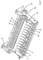
- eine Übersichtsdarstellung eines Teils der Schneidvorrichtung gemäß
Fig. 1 , - Fig. 5
- eine Übersichtsdarstellung des Teils gemäß
Fig. 4 aus einer gegenüberliegenden Perspektive, - Fig. 6
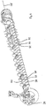
- eine Übersichtsdarstellung einer Schaltwelle einer erfindungsgemäßen Schneidvorrichtung,
- Fig. 7
- einen schematischen Längsschnitt einer erfindungsgemäßen Ballenpresse mit der Schneidvorrichtung gemäß
Fig. 1 . - Die nachfolgend erläuterten Merkmale der erfindungsgemäßen Ausführungsbeispiele können auch einzeln oder in anderen Kombinationen als dargestellt oder beschrieben Gegenstand der Erfindung sein, stets aber zumindest in Kombination mit den Merkmalen des Anspruchs 1. Sofern sinnvoll, sind funktional gleichwirkende Teile mit identischen Bezugsziffern versehen.
- Die
Fig. 1 bis 3 zeigen eine erfindungsgemäße Schneidvorrichtung 2 in einem Längsschnitt. Die Schneidvorrichtung 2 bildet einen Förderkanal 4, durch den im Betrieb insbesondere landwirtschaftliches Schneidgut gefördert und dabei insbesondere geschnitten wird. Der Förderkanal 4 wird begrenzt durch einen Förder- und Schneidrotor 54 einerseits und eine Förderkanalwandung 56 andererseits. Die Schneidvorrichtung 2 hat eine Mehrzahl von schwenkbar gelagerten Schneidelementen 6 (vergl. auchFig. 4 ), wovon in denFig. 1 bis 3 jeweils eines dargestellt ist. Das Schneidelement 6 ist durch eine Bewegung in eine erste Schwenkrichtung 8 aus einer Ruhestellung (vergl.Fig. 3 ) in eine Schneidstellung (vergl.Fig. 1 ) überführbar. In der Schneidstellung ist das Schneidelement 6 zum Schneiden des Schneidgutes mit einer Schneide im Förderkanal 4 positioniert. - Die Schneidvorrichtung 2 hat eine Stellvorrichtung (I) zum Rückführen des Schneidelementes 6 in die Schneidstellung und zum Halten des Schneidelementes 6 in der Schneidstellung. Die Stellvorrichtung (I) umfasst ein Stellelement 22 und ein Rückstellelement 10. Das Stellelement 22 ist schwenkbar um eine Stellschwenkachse 36 gelagert. Das Rückstellelement 10 ist einenends ortsfest an einem Maschinenrahmen und anderenends an einem zweiten Schenkel 44 des Stellelementes 22 angeordnet.
- In der Schneidstellung des Schneidelementes 6 liegt das Stellelement 22 mit einer Rolle an einem ersten Oberflächenabschnitt 18 des Schneidelementes 6 an. Durch eine Zugkraft des Rückstellelementes 10 wird das Stellelement 22 in eine Vertiefung des Schneidelementes 6 gezogen, wodurch das Schneidelement 6 im Betrieb möglichst in der Schneidstellung verbleibt.
- Zur Überführung des Schneidelementes 6 aus der Ruhestellung in die Schneidstellung wird das Stellelement 22 aus seiner in
Fig. 3 dargestellten Position an den ersten Oberflächenabschnitt 18 angelegt. Dadurch wird ein erstes Drehmoment in die Schwenkrichtung 8 auf das Schneidelement 6 aufgebracht. Dadurch ist das Schneidelement regelmäßig aus der Ruhestellung zu lösen und gleitet aufwärts und an dem Stellelement 22 entlang. Aufgrund des dabei stattfindenden Annäherns des zweiten Schenkels 44 des Stellelementes 22 an die Schwenkachse des Schneidelementes 6 und die damit einhergehende Verkürzung des Rückstellelementes 10 sinkt das auf das Schneidelement 6 aufgebrachte Drehmoment mit dem Hinaufschwenken des Schneidelementes 6, ausgehend vom ersten Drehmoment, ab. - Bei Auftreten eines Fremdkörpers, insbesondere eines Steins im Betrieb der Schneidvorrichtung 2 innerhalb des Förderkanals 4 ermöglicht die Stellvorrichtung (I) ein Zurückschwenken des Schneidelementes 6 aus der Schneidstellung entgegen der Zugkraft des Rückstellelementes 10. Nach Passieren des Fremdkörpers bewirkt das Rückstellelement 10 ein Rückstellen des Schneidelementes 6 in die Schneidstellung.
- Zu einer Überführung des Schneidelementes 6 aus der Schneidstellung in die Ruhestellung dient ein Kuppelelement 26 sowie die Schaltwelle 28. Das Kuppelelement 26 ist wie das Stellelement 22 schwenkbar um die Stellschwenkachse 36 gelagert. Zur Ermöglichung eines schwerkraftbedingten Rückschwenkens des Schneidelementes 6 in die Ruhestellung lässt sich das Kuppelelement 26 zunächst gegen einen Kuppelkontaktbereich 40 des Stellelementes 22 verschwenken (vergl.
Fig. 2 ). Diese Verschwenkung ist insbesondere mit einem mit dem Kuppelelement gekoppelten Hydraulikzylinder 24 (vergl.Fig. 5 ) herbeizuführen. Der Kuppelkontaktbereich 40 ist dabei an einem ersten Schenkel 34 des Stellelementes 22 angeordnet. - Nach einer Überführung des Kuppelelementes 26 in die in
Fig. 2 dargestellte Kuppelstellung ist das Stellelement 22 sowohl von dem Schneidelement 6 als auch von der Schaltwelle 28 beabstandet. Die Schaltwelle 28 ist um eine Schaltwellenachse 58 drehbar gelagert und umfasst entlang ihres Umfangs mehrere Schaltelemente 38. Die Schaltwelle 28 ist inFig. 1 einer ersten Schaltstellung zur Positionierung des Schneidelementes 6 in der Schneidstellung angeordnet. Nach Beabstandung des Stellelementes 22 von der Schaltwelle 28 ist die Schaltwelle 28 durch Verschwenkungen um < 360° in weitere Schaltstellungen wie z.B. inFig. 2 überführbar. In den weiteren Schaltstellungen ist dem Schaltkontaktbereich 32 entgegen den ersten Schaltstellungen ein Schaltelement 38 zur Positionierung des Schneidelementes 6 in der Ruhestellung zugewandt. - Nach einer Überführung der Schaltwelle 28 in eine weitere Schaltstellung lässt sich das Kuppelelement 26 aus der Kuppelstellung (vergl.
Fig. 2 ) in eine Lösestellung (vergl.Fig. 3 ) von einem Kuppelrückstellelement 42 rücküberführen. Bedingt durch das Rückstellelement 10 folgt das Stellelement 22 der Bewegung des Kuppelelementes 26 dabei so weit, bis das Stellelement 22 mit einem Schaltkontaktbereich an einem der Schaltelemente 38 der Schaltwelle 28 anliegt. Der Schaltkontaktbereich 32 ist dabei am ersten Schenkel 34 des Stellelementes 22 angeordnet. Der Schaltkontaktbereich 32 weist eine Vertiefung auf, in die sich das eine Schaltelement 38 in der weiteren Schaltstellung und nach Lösen des Kuppelelementes 26 teilweise erstreckt (vergl.Fig. 3 ). Dadurch wird ein Kontakt zwischen dem Schneidelement 6 und dem Stellelement 22 vermieden, wodurch das Schneidelement 6 in der Ruhestellung verbleibt. Eine Überführung der Schaltwelle 28 von der weiteren Schaltstellung in eine erste Schaltstellung lässt sich analog herbeiführen. - Starr mit dem Kuppelelement 26 verbunden ist ein Zweitstellelement 16 einer zweiten Stellvorrichtung (II). Das Zweitstellelement 16 ist damit ebenso wie das Kuppelelement 26 um die Stellschwenkachse 36 verschwenkbar. Dabei ist das Zweitstellelement 16 mit einem zweiten Oberflächenabschnitt 20 des Schneidelementes 6 in Kontakt zu bringen.
- Das Zweitstellelement 16 dient zum Verschwenken des Schneidelementes 6 aus der Ruhestellung in die erste Schwenkrichtung 8. Das Zweitstellelement 16 ist zum Aufbringen eines zweiten Drehmomentes auf das Schneidelement 6 in der Ruhestellung ausgebildet, wobei das zweite Drehmoment größer ist als das von der Stellvorrichtung (I) auf das Schneidelement 6 aufzubringende erste Drehmoment in der Ruhestellung. Das zweite Drehmoment ist so groß, dass das Schneidelement 6 auch bei Vorhandensein von Schneidgutablagerungen zwischen dem Schneidelement 6 und der Förderkanalwandung 56 zuverlässig aus der Ruhestellung in die erste Schwenkrichtung 8 verschwenkt werden kann, wenn ein solches Verschwenken durch das kleinere erste Drehmoment nicht mehr zu verwirklichen ist.
- Das Zweitstellelement 16 erstreckt sich unterhalb einer Mehrzahl von Schneidelementen 6 (vergl.
Fig. 5 ). Jedem Schneidelement 6 ist dabei eine Stellvorrichtung (I) mit je einem Stellelement 22 zugeordnet. Das Kuppelelement 26 hat ebenso wie das Zweitstellelement 16 eine Breite, die im Wesentlichen einer Breite des Förderkanals 4 entspricht, wodurch durch das Kuppelelement 26 sämtliche Stellelemente 22 sowohl von dem jeweiligen Schneidelement 6 als auch von der Schaltwelle 28 gelöst werden können. - Die Schneidvorrichtung 2 hat eine einen Hydraulikmotor 46 aufweisende Antriebsvorrichtung zu einer kontinuierlichen Rotation der Schaltwelle 28 um mehr als 360° (vergl.
Fig. 4 und5 ). Außerdem hat die Schneidvorrichtung 2 eine nicht dargestellte Sperrvorrichtung zur Sperrung der Antriebsvorrichtung bei Anliegen des Schaltkontaktbereichs 32 an der Schaltwelle 28, insbesondere bei fehlender Anordnung des Kuppelelementes 26 in der Kuppelstellung. - Der Hydraulikmotor 46 ist über ein nicht gezeigtes Getriebe zur Untersetzung seiner Antriebsdrehzahl mit der Schaltwelle 28 gekoppelt. Durch einen Winkelsensor ist die Antriebsvorrichtung zur automatischen Einstellung unterschiedlicher Schaltstellungen der Schaltwelle 28 ausgebildet.
- Die Schaltelemente 38 der Schaltwelle 28 haben eine radiale Erstreckung von der Schaltwellenachse 58, die mehr als 1,3-fach so groß ist wie die radiale Erstreckung eines zylinderförmigen Abschnittes 50 der Schaltwelle 28 von der Schaltwellenachse 58 (vergl.
Fig. 6 ). Zwischen zwei in Richtung der Schaltwellenachse 58 benachbarten Schaltelementen 38 weist die Schaltwelle 28 insbesondere ein Förderelement 52 auf.Fig. 6 zeigt exemplarische Förderelemente 52 nur auf einem Abschnitt der Schaltwelle 28. Bevorzugt sind derartige Förderelemente 52 entlang der gesamten Schaltwellenlänge an der Schaltwelle 28 angeordnet. -
Fig. 7 zeigt eine Ballenpresse 30 mit einer erfindungsgemäßen Schneidvorrichtung 2. Im Betrieb wird die Ballenpresse 30 in eine Fahrtrichtung 60 fortbewegt und dabei landwirtschaftliches Schneidgut wie Heu oder Stroh vom Erdboden aufgenommen und unter anderem vom Förder- und Schneidrotor 54 durch den Förderkanal 4 gefördert. Dabei wird es unter anderem von dem in Schneidstellung dargestellten Schneidelement geschnitten und anschließend einer Ballenkammer zur Ausbildung eines Rundballens zugeführt.
Claims (15)
- Schneidvorrichtung (2) zum Fördern und Schneiden insbesondere landwirtschaftlichen Schneidgutes, mit einem Förderkanal (4) und zumindest einem schwenkbar gelagerten Schneidelement (6), welches durch eine Bewegung in eine erste Schwenkrichtung (8) aus einer Ruhestellung in eine Schneidstellung überführbar ist, in der das Schneidelement (6) zum Schneiden des Schneidgutes zumindest teilweise innerhalb des Förderkanals (4) positioniert ist, mit einer Stellvorrichtung (I), umfassend ein zumindest in der Schneidstellung des Schneidelementes (6) im Betrieb am Schneidelement (6) anliegendes und insbesondere schwenkbar um eine Stellschwenkachse (36) gelagertes Stellelement (22), mit einer in unterschiedliche Schaltstellungen überführbaren, drehbar um eine Schaltwellenachse (58) gelagerten Schaltwelle (28), mit der das Stellelement (22) in zumindest einer der Schaltstellungen der Schaltwelle (28) im Betrieb gekoppelt ist, und mit einem Rückstellelement (10) zum Rückführen des Schneidelementes (6) in die Schneidstellung und zum Halten des Schneidelementes (6) in der Schneidstellung,
dadurch gekennzeichnet, dass das Stellelement (22) einen in der Schaltstellung im Betrieb an der Schaltwelle (28) anliegenden Schaltkontaktbereich (32) hat. - Schneidvorrichtung (2) nach Anspruch 1, dadurch gekennzeichnet, dass der Schaltkontaktbereich (32) von einem ersten Schenkel (34) des Stellelementes (22) umfasst ist, der sich im Betrieb in der Schneidstellung des Schneidelementes (6) von der Stellschwenkachse (36) aus vom Schneidelement (6) wegerstreckt.
- Schneidvorrichtung (2) nach Anspruch 1 oder 2, dadurch gekennzeichnet, dass der Schaltkontaktbereich (32) eine Vertiefung aufweist, in die sich in der Schaltstellung im Betrieb ein Schaltelement (38) der Schaltwelle (28) erstreckt.
- Schneidvorrichtung (2) nach einem der vorhergehenden Ansprüche, gekennzeichnet durch ein Kuppelelement (26), das zum Lösen des Stellelementes (22) von der Schaltwelle (28) ausgebildet ist und in einer Kuppelstellung insbesondere an einem Kuppelkontaktbereich (40) des Stellelementes (22) anliegt.
- Schneidvorrichtung (2) nach Anspruch 4, dadurch gekennzeichnet, dass der Kuppelkontaktbereich (40) weiter von der Stellschwenkachse (36) beabstandet ist als der Schaltkontaktbereich (32) und/oder Teil des ersten Schenkels (34) des Stellelementes (22) ist.
- Schneidvorrichtung (2) nach Anspruch 4 oder 5, dadurch gekennzeichnet, dass das Kuppelelement (26) um die ortsfeste Stellschwenkachse (36) schwenkbar gelagert sind.
- Schneidvorrichtung (2) nach einem der Ansprüche 4 bis 6, dadurch gekennzeichnet, dass am Kuppelelement (26) ein das Kuppelelement (26) aus der Kuppelstellung rückführendes Kuppelrückstellelement (42) angeordnet ist.
- Schneidvorrichtung (2) nach einem der vorhergehenden Ansprüche, dadurch gekennzeichnet, dass das Betriebsrückstellelement (10) an einem zweiten Schenkel (44) des Stellelementes (22) angeordnet ist, der sich in der Schneidstellung des Schneidelementes (6) von einer Stellschwenkachse (36) zum Schneidelement (6) erstreckt.
- Schneidvorrichtung (2) nach einem der vorhergehenden Ansprüche, dadurch gekennzeichnet, dass die Stellvorrichtung (I) derart ausgebildet ist, dass das Schneidelement (6) im Betrieb und bei Anliegen des Schaltkontaktbereichs (32) an der Schaltwelle (28) in der Ruhestellung angeordnet ist.
- Schneidvorrichtung (2) nach einem der vorhergehenden Ansprüche, gekennzeichnet durch eine zu einer kontinuierlichen Rotation der Schaltwelle (28) um > 360° ausgebildete Antriebsvorrichtung.
- Schneidvorrichtung (2) nach Anspruch 10, gekennzeichnet durch eine Sperrvorrichtung, die zur Sperrung der Antriebsvorrichtung bei Anliegen des Schaltkontaktbereiches (32) an der Schaltwelle (28), insbesondere bei fehlender Anordnung des Kuppelelementes (26) in der Kuppelstellung ausgebildet ist.
- Schneidvorrichtung (2) nach Anspruch 10 oder 11, dadurch gekennzeichnet, dass eine radiale Erstreckung eines Schaltelementes (38) von der Schaltwellenachse (58) mindestens 1,3-fach, insbesondere mindestens 1,5-fach, so groß ist wie die radiale Erstreckung eines zumindest im Wesentlichen zylinderförmigen Abschnittes (50) der Schaltwelle (28) von der Schaltwellenachse (58).
- Schneidvorrichtung (2) nach einem der vorhergehenden Ansprüche, dadurch gekennzeichnet, dass die Schaltwelle (28) zwischen zwei in Richtung der Schaltwellenachse (58) voneinander beabstandeten Schaltelementen (38) zumindest ein Förderelement (52) aufweist, dessen radiale Erstreckung von der Schaltwellenachse (58) größer ist als die radiale Erstreckung der Schaltelemente (38) von der Schaltwellenachse (58).
- Schneidvorrichtung (2) nach einem der vorhergehenden Ansprüche, dadurch gekennzeichnet, dass zumindest ein mit der Schaltwelle (28) gekoppeltes und in Abhängigkeit von dessen Rotation rotierendes Reinigungselement vorgesehen ist, dessen Rotationsachse parallel zur Schaltwellenachse (58) angeordnet ist.
- Landwirtschaftliche Maschine, insbesondere Ballenpresse (30) oder Ladewagen, mit einer Schneidvorrichtung (2) nach einem der vorhergehenden Ansprüche.
Priority Applications (1)
| Application Number | Priority Date | Filing Date | Title |
|---|---|---|---|
| PL20000118T PL3729953T3 (pl) | 2019-03-21 | 2020-03-19 | Urządzenie tnące |
Applications Claiming Priority (1)
| Application Number | Priority Date | Filing Date | Title |
|---|---|---|---|
| DE102019002029 | 2019-03-21 |
Publications (2)
| Publication Number | Publication Date |
|---|---|
| EP3729953A1 true EP3729953A1 (de) | 2020-10-28 |
| EP3729953B1 EP3729953B1 (de) | 2021-12-22 |
Family
ID=69941124
Family Applications (1)
| Application Number | Title | Priority Date | Filing Date |
|---|---|---|---|
| EP20000118.8A Active EP3729953B1 (de) | 2019-03-21 | 2020-03-19 | Schneidvorrichtung |
Country Status (3)
| Country | Link |
|---|---|
| EP (1) | EP3729953B1 (de) |
| DE (1) | DE102019005937A1 (de) |
| PL (1) | PL3729953T3 (de) |
Cited By (1)
| Publication number | Priority date | Publication date | Assignee | Title |
|---|---|---|---|---|
| GB2625401A (en) * | 2022-12-14 | 2024-06-19 | Kuhn Geldrop Bv | Cutter device for an agricultural harvester |
Citations (2)
| Publication number | Priority date | Publication date | Assignee | Title |
|---|---|---|---|---|
| US6912835B1 (en) * | 2004-06-25 | 2005-07-05 | Deere & Company | Knife selecting arrangement of crop cutting device for use with agricultural machines having a pick-up |
| DE202014006083U1 (de) | 2014-07-30 | 2015-11-04 | Maschinenfabrik Bernard Krone Gmbh | Schneideinrichtung für landwirtschaftliche Erntemaschinen |
-
2019
- 2019-08-22 DE DE102019005937.9A patent/DE102019005937A1/de not_active Ceased
-
2020
- 2020-03-19 EP EP20000118.8A patent/EP3729953B1/de active Active
- 2020-03-19 PL PL20000118T patent/PL3729953T3/pl unknown
Patent Citations (2)
| Publication number | Priority date | Publication date | Assignee | Title |
|---|---|---|---|---|
| US6912835B1 (en) * | 2004-06-25 | 2005-07-05 | Deere & Company | Knife selecting arrangement of crop cutting device for use with agricultural machines having a pick-up |
| DE202014006083U1 (de) | 2014-07-30 | 2015-11-04 | Maschinenfabrik Bernard Krone Gmbh | Schneideinrichtung für landwirtschaftliche Erntemaschinen |
Cited By (1)
| Publication number | Priority date | Publication date | Assignee | Title |
|---|---|---|---|---|
| GB2625401A (en) * | 2022-12-14 | 2024-06-19 | Kuhn Geldrop Bv | Cutter device for an agricultural harvester |
Also Published As
| Publication number | Publication date |
|---|---|
| DE102019005937A1 (de) | 2020-09-24 |
| EP3729953B1 (de) | 2021-12-22 |
| PL3729953T3 (pl) | 2022-04-25 |
Similar Documents
| Publication | Publication Date | Title |
|---|---|---|
| DE69707050T2 (de) | Ernteaufsammeleinrichtung | |
| EP2979535B1 (de) | Schneideinrichtung für landwirtschaftliche erntemaschinen | |
| DE69323738T2 (de) | Ballenpresszuführmechanismus | |
| EP0903077A1 (de) | Aufnahmeeinheit für Erntegut | |
| DE1710190B2 (de) | Steuervorrichtung fuer die schaefte von webmaschinen | |
| EP3732953B1 (de) | Schneidvorrichtung | |
| DE19534138C1 (de) | Ballenpresse für Erntegut | |
| DE2620036C3 (de) | Abstreifeinrichtung für Förderbänder | |
| EP3729953B1 (de) | Schneidvorrichtung | |
| EP0499064B1 (de) | Maschine zum Aufnehmen und Pressen von landwirtschaftlichem Erntegut | |
| EP1864567B1 (de) | Gutaufnehmer | |
| DE2262826A1 (de) | Maehwerkhaspel mit zinkensteuerung | |
| EP1306003A1 (de) | Ballenpresse für landwirtschaftliches Erntegut | |
| EP3932177B1 (de) | Aufnahmevorrichtung mit auf einer trommel befestigten förderzinken | |
| DE3000564A1 (de) | Heuwerbungsmaschine | |
| EP3951128B1 (de) | Vorrichtung zum räumen eines wendelzwischenraumes einer bohrschnecke und verfahren zum erstellen einer bohrung | |
| DE3028140A1 (de) | Ladewagen fuer landwirtschaftliche massengueter | |
| EP0073900B1 (de) | Heuwerbungsmaschine | |
| DE1940172C3 (de) | Heuwerbungsmaschine | |
| DE2904244A1 (de) | Heuwerbungsmaschine | |
| EP4056026A1 (de) | Fördervorrichtung für eine ballenpresse | |
| DE20016238U1 (de) | Garnkuppler | |
| DE69107369T2 (de) | Einrückmechanismus für Hüllvorrichtung. | |
| DE19720542A1 (de) | Vorrichtung und Verfahren zur Sicherung von Garnenden | |
| DE3529201A1 (de) | Ladewagen |
Legal Events
| Date | Code | Title | Description |
|---|---|---|---|
| PUAI | Public reference made under article 153(3) epc to a published international application that has entered the european phase |
Free format text: ORIGINAL CODE: 0009012 |
|
| STAA | Information on the status of an ep patent application or granted ep patent |
Free format text: STATUS: THE APPLICATION HAS BEEN PUBLISHED |
|
| AK | Designated contracting states |
Kind code of ref document: A1 Designated state(s): AL AT BE BG CH CY CZ DE DK EE ES FI FR GB GR HR HU IE IS IT LI LT LU LV MC MK MT NL NO PL PT RO RS SE SI SK SM TR |
|
| AX | Request for extension of the european patent |
Extension state: BA ME |
|
| STAA | Information on the status of an ep patent application or granted ep patent |
Free format text: STATUS: REQUEST FOR EXAMINATION WAS MADE |
|
| 17P | Request for examination filed |
Effective date: 20210407 |
|
| RBV | Designated contracting states (corrected) |
Designated state(s): AL AT BE BG CH CY CZ DE DK EE ES FI FR GB GR HR HU IE IS IT LI LT LU LV MC MK MT NL NO PL PT RO RS SE SI SK SM TR |
|
| GRAP | Despatch of communication of intention to grant a patent |
Free format text: ORIGINAL CODE: EPIDOSNIGR1 |
|
| STAA | Information on the status of an ep patent application or granted ep patent |
Free format text: STATUS: GRANT OF PATENT IS INTENDED |
|
| RIC1 | Information provided on ipc code assigned before grant |
Ipc: A01D 90/06 20060101ALI20210812BHEP Ipc: A01F 15/10 20060101AFI20210812BHEP |
|
| INTG | Intention to grant announced |
Effective date: 20210915 |
|
| GRAS | Grant fee paid |
Free format text: ORIGINAL CODE: EPIDOSNIGR3 |
|
| GRAA | (expected) grant |
Free format text: ORIGINAL CODE: 0009210 |
|
| STAA | Information on the status of an ep patent application or granted ep patent |
Free format text: STATUS: THE PATENT HAS BEEN GRANTED |
|
| AK | Designated contracting states |
Kind code of ref document: B1 Designated state(s): AL AT BE BG CH CY CZ DE DK EE ES FI FR GB GR HR HU IE IS IT LI LT LU LV MC MK MT NL NO PL PT RO RS SE SI SK SM TR |
|
| REG | Reference to a national code |
Ref country code: GB Ref legal event code: FG4D Free format text: NOT ENGLISH |
|
| REG | Reference to a national code |
Ref country code: CH Ref legal event code: EP |
|
| REG | Reference to a national code |
Ref country code: DE Ref legal event code: R096 Ref document number: 502020000452 Country of ref document: DE |
|
| REG | Reference to a national code |
Ref country code: AT Ref legal event code: REF Ref document number: 1456482 Country of ref document: AT Kind code of ref document: T Effective date: 20220115 |
|
| REG | Reference to a national code |
Ref country code: IE Ref legal event code: FG4D Free format text: LANGUAGE OF EP DOCUMENT: GERMAN |
|
| REG | Reference to a national code |
Ref country code: NL Ref legal event code: FP |
|
| REG | Reference to a national code |
Ref country code: LT Ref legal event code: MG9D |
|
| PG25 | Lapsed in a contracting state [announced via postgrant information from national office to epo] |
Ref country code: RS Free format text: LAPSE BECAUSE OF FAILURE TO SUBMIT A TRANSLATION OF THE DESCRIPTION OR TO PAY THE FEE WITHIN THE PRESCRIBED TIME-LIMIT Effective date: 20211222 Ref country code: LT Free format text: LAPSE BECAUSE OF FAILURE TO SUBMIT A TRANSLATION OF THE DESCRIPTION OR TO PAY THE FEE WITHIN THE PRESCRIBED TIME-LIMIT Effective date: 20211222 Ref country code: FI Free format text: LAPSE BECAUSE OF FAILURE TO SUBMIT A TRANSLATION OF THE DESCRIPTION OR TO PAY THE FEE WITHIN THE PRESCRIBED TIME-LIMIT Effective date: 20211222 Ref country code: BG Free format text: LAPSE BECAUSE OF FAILURE TO SUBMIT A TRANSLATION OF THE DESCRIPTION OR TO PAY THE FEE WITHIN THE PRESCRIBED TIME-LIMIT Effective date: 20220322 |
|
| PG25 | Lapsed in a contracting state [announced via postgrant information from national office to epo] |
Ref country code: SE Free format text: LAPSE BECAUSE OF FAILURE TO SUBMIT A TRANSLATION OF THE DESCRIPTION OR TO PAY THE FEE WITHIN THE PRESCRIBED TIME-LIMIT Effective date: 20211222 Ref country code: NO Free format text: LAPSE BECAUSE OF FAILURE TO SUBMIT A TRANSLATION OF THE DESCRIPTION OR TO PAY THE FEE WITHIN THE PRESCRIBED TIME-LIMIT Effective date: 20220322 Ref country code: LV Free format text: LAPSE BECAUSE OF FAILURE TO SUBMIT A TRANSLATION OF THE DESCRIPTION OR TO PAY THE FEE WITHIN THE PRESCRIBED TIME-LIMIT Effective date: 20211222 Ref country code: HR Free format text: LAPSE BECAUSE OF FAILURE TO SUBMIT A TRANSLATION OF THE DESCRIPTION OR TO PAY THE FEE WITHIN THE PRESCRIBED TIME-LIMIT Effective date: 20211222 Ref country code: GR Free format text: LAPSE BECAUSE OF FAILURE TO SUBMIT A TRANSLATION OF THE DESCRIPTION OR TO PAY THE FEE WITHIN THE PRESCRIBED TIME-LIMIT Effective date: 20220323 |
|
| PG25 | Lapsed in a contracting state [announced via postgrant information from national office to epo] |
Ref country code: SM Free format text: LAPSE BECAUSE OF FAILURE TO SUBMIT A TRANSLATION OF THE DESCRIPTION OR TO PAY THE FEE WITHIN THE PRESCRIBED TIME-LIMIT Effective date: 20211222 Ref country code: SK Free format text: LAPSE BECAUSE OF FAILURE TO SUBMIT A TRANSLATION OF THE DESCRIPTION OR TO PAY THE FEE WITHIN THE PRESCRIBED TIME-LIMIT Effective date: 20211222 Ref country code: RO Free format text: LAPSE BECAUSE OF FAILURE TO SUBMIT A TRANSLATION OF THE DESCRIPTION OR TO PAY THE FEE WITHIN THE PRESCRIBED TIME-LIMIT Effective date: 20211222 Ref country code: PT Free format text: LAPSE BECAUSE OF FAILURE TO SUBMIT A TRANSLATION OF THE DESCRIPTION OR TO PAY THE FEE WITHIN THE PRESCRIBED TIME-LIMIT Effective date: 20220422 Ref country code: ES Free format text: LAPSE BECAUSE OF FAILURE TO SUBMIT A TRANSLATION OF THE DESCRIPTION OR TO PAY THE FEE WITHIN THE PRESCRIBED TIME-LIMIT Effective date: 20211222 Ref country code: EE Free format text: LAPSE BECAUSE OF FAILURE TO SUBMIT A TRANSLATION OF THE DESCRIPTION OR TO PAY THE FEE WITHIN THE PRESCRIBED TIME-LIMIT Effective date: 20211222 Ref country code: CZ Free format text: LAPSE BECAUSE OF FAILURE TO SUBMIT A TRANSLATION OF THE DESCRIPTION OR TO PAY THE FEE WITHIN THE PRESCRIBED TIME-LIMIT Effective date: 20211222 |
|
| REG | Reference to a national code |
Ref country code: DE Ref legal event code: R097 Ref document number: 502020000452 Country of ref document: DE |
|
| PG25 | Lapsed in a contracting state [announced via postgrant information from national office to epo] |
Ref country code: IS Free format text: LAPSE BECAUSE OF FAILURE TO SUBMIT A TRANSLATION OF THE DESCRIPTION OR TO PAY THE FEE WITHIN THE PRESCRIBED TIME-LIMIT Effective date: 20220422 |
|
| PLBE | No opposition filed within time limit |
Free format text: ORIGINAL CODE: 0009261 |
|
| STAA | Information on the status of an ep patent application or granted ep patent |
Free format text: STATUS: NO OPPOSITION FILED WITHIN TIME LIMIT |
|
| PG25 | Lapsed in a contracting state [announced via postgrant information from national office to epo] |
Ref country code: MC Free format text: LAPSE BECAUSE OF FAILURE TO SUBMIT A TRANSLATION OF THE DESCRIPTION OR TO PAY THE FEE WITHIN THE PRESCRIBED TIME-LIMIT Effective date: 20211222 Ref country code: DK Free format text: LAPSE BECAUSE OF FAILURE TO SUBMIT A TRANSLATION OF THE DESCRIPTION OR TO PAY THE FEE WITHIN THE PRESCRIBED TIME-LIMIT Effective date: 20211222 Ref country code: AL Free format text: LAPSE BECAUSE OF FAILURE TO SUBMIT A TRANSLATION OF THE DESCRIPTION OR TO PAY THE FEE WITHIN THE PRESCRIBED TIME-LIMIT Effective date: 20211222 |
|
| 26N | No opposition filed |
Effective date: 20220923 |
|
| PG25 | Lapsed in a contracting state [announced via postgrant information from national office to epo] |
Ref country code: LU Free format text: LAPSE BECAUSE OF NON-PAYMENT OF DUE FEES Effective date: 20220319 |
|
| PG25 | Lapsed in a contracting state [announced via postgrant information from national office to epo] |
Ref country code: SI Free format text: LAPSE BECAUSE OF FAILURE TO SUBMIT A TRANSLATION OF THE DESCRIPTION OR TO PAY THE FEE WITHIN THE PRESCRIBED TIME-LIMIT Effective date: 20211222 |
|
| P01 | Opt-out of the competence of the unified patent court (upc) registered |
Effective date: 20230517 |
|
| REG | Reference to a national code |
Ref country code: CH Ref legal event code: PL |
|
| PG25 | Lapsed in a contracting state [announced via postgrant information from national office to epo] |
Ref country code: LI Free format text: LAPSE BECAUSE OF NON-PAYMENT OF DUE FEES Effective date: 20230331 Ref country code: CH Free format text: LAPSE BECAUSE OF NON-PAYMENT OF DUE FEES Effective date: 20230331 |
|
| PG25 | Lapsed in a contracting state [announced via postgrant information from national office to epo] |
Ref country code: MK Free format text: LAPSE BECAUSE OF FAILURE TO SUBMIT A TRANSLATION OF THE DESCRIPTION OR TO PAY THE FEE WITHIN THE PRESCRIBED TIME-LIMIT Effective date: 20211222 Ref country code: CY Free format text: LAPSE BECAUSE OF FAILURE TO SUBMIT A TRANSLATION OF THE DESCRIPTION OR TO PAY THE FEE WITHIN THE PRESCRIBED TIME-LIMIT Effective date: 20211222 |
|
| PG25 | Lapsed in a contracting state [announced via postgrant information from national office to epo] |
Ref country code: HU Free format text: LAPSE BECAUSE OF FAILURE TO SUBMIT A TRANSLATION OF THE DESCRIPTION OR TO PAY THE FEE WITHIN THE PRESCRIBED TIME-LIMIT; INVALID AB INITIO Effective date: 20200319 |
|
| PG25 | Lapsed in a contracting state [announced via postgrant information from national office to epo] |
Ref country code: TR Free format text: LAPSE BECAUSE OF FAILURE TO SUBMIT A TRANSLATION OF THE DESCRIPTION OR TO PAY THE FEE WITHIN THE PRESCRIBED TIME-LIMIT Effective date: 20211222 |
|
| PG25 | Lapsed in a contracting state [announced via postgrant information from national office to epo] |
Ref country code: MT Free format text: LAPSE BECAUSE OF FAILURE TO SUBMIT A TRANSLATION OF THE DESCRIPTION OR TO PAY THE FEE WITHIN THE PRESCRIBED TIME-LIMIT Effective date: 20211222 |
|
| GBPC | Gb: european patent ceased through non-payment of renewal fee |
Effective date: 20240319 |
|
| PG25 | Lapsed in a contracting state [announced via postgrant information from national office to epo] |
Ref country code: GB Free format text: LAPSE BECAUSE OF NON-PAYMENT OF DUE FEES Effective date: 20240319 |
|
| PG25 | Lapsed in a contracting state [announced via postgrant information from national office to epo] |
Ref country code: GB Free format text: LAPSE BECAUSE OF NON-PAYMENT OF DUE FEES Effective date: 20240319 |
|
| PGFP | Annual fee paid to national office [announced via postgrant information from national office to epo] |
Ref country code: IT Payment date: 20250331 Year of fee payment: 6 |
|
| PGFP | Annual fee paid to national office [announced via postgrant information from national office to epo] |
Ref country code: DE Payment date: 20260320 Year of fee payment: 7 Ref country code: IE Payment date: 20260323 Year of fee payment: 7 |
|
| PGFP | Annual fee paid to national office [announced via postgrant information from national office to epo] |
Ref country code: AT Payment date: 20260319 Year of fee payment: 7 |
|
| PGFP | Annual fee paid to national office [announced via postgrant information from national office to epo] |
Ref country code: BE Payment date: 20260323 Year of fee payment: 7 |
|
| PGFP | Annual fee paid to national office [announced via postgrant information from national office to epo] |
Ref country code: NL Payment date: 20260323 Year of fee payment: 7 |
|
| PGFP | Annual fee paid to national office [announced via postgrant information from national office to epo] |
Ref country code: FR Payment date: 20260325 Year of fee payment: 7 |
|
| PGFP | Annual fee paid to national office [announced via postgrant information from national office to epo] |
Ref country code: PL Payment date: 20260306 Year of fee payment: 7 |