EP3728876B1 - Hydraulische mehrkammer-mehrschrauben-spannvorrichtungen - Google Patents
Hydraulische mehrkammer-mehrschrauben-spannvorrichtungen Download PDFInfo
- Publication number
- EP3728876B1 EP3728876B1 EP18892720.6A EP18892720A EP3728876B1 EP 3728876 B1 EP3728876 B1 EP 3728876B1 EP 18892720 A EP18892720 A EP 18892720A EP 3728876 B1 EP3728876 B1 EP 3728876B1
- Authority
- EP
- European Patent Office
- Prior art keywords
- body section
- hydraulic
- load bearing
- piston
- fastening member
- Prior art date
- Legal status (The legal status is an assumption and is not a legal conclusion. Google has not performed a legal analysis and makes no representation as to the accuracy of the status listed.)
- Active
Links
Images


Classifications
-
- B—PERFORMING OPERATIONS; TRANSPORTING
- B25—HAND TOOLS; PORTABLE POWER-DRIVEN TOOLS; MANIPULATORS
- B25B—TOOLS OR BENCH DEVICES NOT OTHERWISE PROVIDED FOR, FOR FASTENING, CONNECTING, DISENGAGING OR HOLDING
- B25B29/00—Accessories
- B25B29/02—Bolt tensioners
-
- F—MECHANICAL ENGINEERING; LIGHTING; HEATING; WEAPONS; BLASTING
- F16—ENGINEERING ELEMENTS AND UNITS; GENERAL MEASURES FOR PRODUCING AND MAINTAINING EFFECTIVE FUNCTIONING OF MACHINES OR INSTALLATIONS; THERMAL INSULATION IN GENERAL
- F16B—DEVICES FOR FASTENING OR SECURING CONSTRUCTIONAL ELEMENTS OR MACHINE PARTS TOGETHER, e.g. NAILS, BOLTS, CIRCLIPS, CLAMPS, CLIPS OR WEDGES; JOINTS OR JOINTING
- F16B31/00—Screwed connections specially modified in view of tensile load; Break-bolts
- F16B31/04—Screwed connections specially modified in view of tensile load; Break-bolts for maintaining a tensile load
- F16B31/043—Prestressed connections tensioned by means of liquid, grease, rubber, explosive charge, or the like
-
- B—PERFORMING OPERATIONS; TRANSPORTING
- B23—MACHINE TOOLS; METAL-WORKING NOT OTHERWISE PROVIDED FOR
- B23P—METAL-WORKING NOT OTHERWISE PROVIDED FOR; COMBINED OPERATIONS; UNIVERSAL MACHINE TOOLS
- B23P19/00—Machines for simply fitting together or separating metal parts or objects, or metal and non-metal parts, whether or not involving some deformation; Tools or devices therefor so far as not provided for in other classes
- B23P19/04—Machines for simply fitting together or separating metal parts or objects, or metal and non-metal parts, whether or not involving some deformation; Tools or devices therefor so far as not provided for in other classes for assembling or disassembling parts
- B23P19/06—Screw or nut setting or loosening machines
- B23P19/067—Bolt tensioners
-
- F—MECHANICAL ENGINEERING; LIGHTING; HEATING; WEAPONS; BLASTING
- F16—ENGINEERING ELEMENTS AND UNITS; GENERAL MEASURES FOR PRODUCING AND MAINTAINING EFFECTIVE FUNCTIONING OF MACHINES OR INSTALLATIONS; THERMAL INSULATION IN GENERAL
- F16B—DEVICES FOR FASTENING OR SECURING CONSTRUCTIONAL ELEMENTS OR MACHINE PARTS TOGETHER, e.g. NAILS, BOLTS, CIRCLIPS, CLAMPS, CLIPS OR WEDGES; JOINTS OR JOINTING
- F16B31/00—Screwed connections specially modified in view of tensile load; Break-bolts
- F16B31/04—Screwed connections specially modified in view of tensile load; Break-bolts for maintaining a tensile load
-
- F—MECHANICAL ENGINEERING; LIGHTING; HEATING; WEAPONS; BLASTING
- F16—ENGINEERING ELEMENTS AND UNITS; GENERAL MEASURES FOR PRODUCING AND MAINTAINING EFFECTIVE FUNCTIONING OF MACHINES OR INSTALLATIONS; THERMAL INSULATION IN GENERAL
- F16D—COUPLINGS FOR TRANSMITTING ROTATION; CLUTCHES; BRAKES
- F16D1/00—Couplings for rigidly connecting two coaxial shafts or other movable machine elements
- F16D1/02—Couplings for rigidly connecting two coaxial shafts or other movable machine elements for connecting two abutting shafts or the like
- F16D1/033—Couplings for rigidly connecting two coaxial shafts or other movable machine elements for connecting two abutting shafts or the like by clamping together two faces perpendicular to the axis of rotation, e.g. with bolted flanges
-
- F—MECHANICAL ENGINEERING; LIGHTING; HEATING; WEAPONS; BLASTING
- F16—ENGINEERING ELEMENTS AND UNITS; GENERAL MEASURES FOR PRODUCING AND MAINTAINING EFFECTIVE FUNCTIONING OF MACHINES OR INSTALLATIONS; THERMAL INSULATION IN GENERAL
- F16B—DEVICES FOR FASTENING OR SECURING CONSTRUCTIONAL ELEMENTS OR MACHINE PARTS TOGETHER, e.g. NAILS, BOLTS, CIRCLIPS, CLAMPS, CLIPS OR WEDGES; JOINTS OR JOINTING
- F16B2200/00—Constructional details of connections not covered for in other groups of this subclass
- F16B2200/89—Use of a hydraulic action
Definitions
- the present disclosure generally relates to hydraulically assisted fastening and/ or tensioning devices, and methods of using the same.
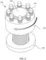
- FIG. 1 is a partially cutaway version of a nut-style MJT 200.
- the MJT 200 comprises an annular body 202.
- the body 202 of the MJT 200 is formed with a threaded central hole 205 to receive a bolt, shaft, or stud.
- Corresponding jack bolts 204 traverse the jack bolt holes 201 and are threadedly received therein.
- the MJT 200 further includes a load bearing member in the form of a hardened washer 206 against which points of the jack bolts 204 abut in use.
- the hardened washer 206 bears against a workpiece being fastened.
- a bolt-style MJT generally comprises a body having a threaded shaft that may be used for blind tapped holes and counterbores.
- MJTs are commercially available from Superbolt, Carnegie PA. Further discussions of MJTs may be found in U.S. Pat. Nos. 4,622,730 , RE33,490 , 4,927,305 , 5,075,950 , 5,083,889 and 6,112,396 .
- the reference to methods and documents of the prior art should not be taken as an admission or evidence that any such prior art information constitutes common general knowledge.
- FIGS. 2 to 6 illustrate the use of the MJT 200.
- initially hardened washer 206 is installed onto the stud 208.
- the body 202 is then threaded onto the stud 208 until it seats against the hardened washer 206 to tension the joint.
- the jack bolts 204 are withdrawn so that their points do not extend out of the body 202 of the MJT.
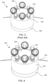
- FIG. 3 once the washer 206 has been located over the stud 208 and the MJT 200 has been threaded onto the stud and into abutment with the washer 206 then four of the jack bolts at 90 degrees apart (i.e.
- a tension preload develops evenly along the stud 208, and the axial forces by the jack bolts 204 and opposite reaction force of the stud 208 create a strong clamping force between the surfaces to be fastened together, such as opposed flanges for example.
- Applying the correct preload is desirable because a pretensioned bolt, shaft or stud may be capable of sustaining a greater load and may reduce the likelihood of the bolt, shaft, or stud loosening unintentionally due to e.g., vibration and/or temperature cycling.
- the hydraulic MJT 310 according to Applicant's earlier invention, the subject of International Patent Application PCT/US2017/037834 , is in the form of a nut and generally comprises an annular body 320 with central axis "L" having a concentric circular threaded hole 325 formed therethrough to receive a stud or bolt (not shown).
- the annular body 320 is formed with a concentric polar array of threaded jack bolt holes therethrough in similar fashion to holes 201 as illustrated in FIG. 1 .
- a piston 340 which in the present embodiment comprises a load bearing member that, in use, applies force to a workpiece to be fastened, such as a pipe flange for example.
- the piston 340 may apply the force to the workpiece via an intermediate member, such as a washer.
- the body 320 and the piston 340 are shaped so that they cooperate to define an annular pressure chamber 350 therebetween.
- the pressure chamber 350 is in fluid communication via a fluid passage 365 with a hydraulic port 360.
- the port 360 may be positioned on the top outer periphery of the body 320 adjacent or proximate to at least one of the jack bolts 330.
- the operation of the hydraulic MJT 310 is further described in the above-referenced '834 application.
- International patent application WO 2007/043143 relates to a liquid pressure device which provides a hydraulic nut that is used to assemble a turbine case.
- the liquid pressure device described in WO 2007/043143 provides a liquid pressure device capable of continuing work even if sealing failure of the pressure chamber occurs.
- Applicant has, in response to further problems experienced with precise control of tension and/or applying appropriate tension to fasteners in a relatively confined space particularly within a limited working envelope, developed a modification or improvement to the earlier invention which conveniently addresses these further problems.
- a multi jack tensioner for applying tension to a fastener, the tensioner comprising:
- a first pressure chamber of the plurality of chambers is defined by a surface of the first body section and a surface of the load bearing member whereby introduction of hydraulic pressure into the first pressure chamber displaces the first body section from the load bearing member.
- the at least one section of the body preferably includes a second body section and wherein a second pressure chamber of the plurality of chambers is defined between a surface of the second body section and a surface of a piston that slides in an opening of the second body section whereby introduction of hydraulic pressure into the second pressure chamber displaces the piston relative to the second body section of the body.
- the first body section preferably includes a portion that extends into the opening of the second body section which is forced away from the second body section by the piston upon the introduction of the hydraulic pressure into the second pressure chamber to thereby displace the first body section from the load bearing member.
- the load bearing member is axially disposed between the first body section and the second body section.
- the portion of the first body section that extends into the opening of the second body section may comprise a lower skirt wherein the first pressure chamber is defined between the load bearing member and the first body section adjacent the lower skirt.
- the load bearing member may be formed as a piston arranged to cooperate with the body.
- the body may be formed in a "nut style" with an axially extending central hole, wherein the first body section thereof is arranged to threadedly engage the elongate fastening member where the elongate fastening member comprises a bolt or stud.
- the body may be formed in a "bolt style" with the elongate fastening member integrally formed with the first section of the body.
- first and second hydraulic fluid ports are provided in fluid communication with the first and second pressure chambers.
- the first and second hydraulic fluid ports preferably extend from the body at right angles to each other.
- the first hydraulic fluid port is located on an end of the first section adjacent heads of the jack bolts and wherein a fluid passage extends from said first port through the first section to the first pressure chamber.
- the second hydraulic fluid port is preferably located on a side of the second section and a fluid passage extends radially from said second port through the second section to the second pressure chamber.
- the first body section may be formed with an axial recess to threadedly engage the elongate fastening member wherein the elongate fastening member comprises a bolt or stud.
- the body portion may be integrally formed with the elongate fastening member.
- the plurality of jack bolts preferably comprises a polar array of jack bolts threadedly received through holes formed spaced uniformly from a longitudinal central axis of the body at spaced apart locations about an outer surface thereof.
- the plurality of jack bolts comprises a polar array of jack bolts threadedly received through holes formed spaced uniformly from a longitudinal central axis of the body at spaced apart locations about an outer surface thereof.
- a piston may be slidingly received within the body section, and a pressure chamber between the body and piston to receive hydraulic fluid through a port and a fluid passage wherein, when the pressure chamber receives hydraulic fluid, the body and piston axially separate.
- a piston may be slidingly received externally of the body section.
- a multi jack tensioner for applying tension to an elongate fastening member, comprising:
- the body is integrally formed with the elongate fastening member.
- the plurality of pressure chambers are axially spaced from one another.
- the load bearing member is formed as a piston arranged to cooperate with the body.
- the load bearing member may be formed as a load cell with which a piston cooperates in order to force the first body section in use.
- the load bearing member may comprise a section of the body housing a piston.
- the plurality of jack bolts may comprise an annular array of jack bolts threadedly received through holes formed spaced uniformly from a longitudinal central axis of the body at spaced apart locations about an outer surface thereof.
- the plurality of jack bolts comprises a polar array of jack bolts threadedly received through holes formed spaced uniformly from a longitudinal central axis of the body at spaced apart locations about an outer surface thereof.
- a piston may be slidingly received within the body section, and a pressure chamber between the body and piston to receive hydraulic fluid through a port and a fluid passage wherein, when the pressure chamber receives hydraulic fluid, the body and piston axially separate.
- a piston may be slidingly received externally of the body section.
- a piston is slidingly received into the body, and a pressure chamber between the body and piston to receive hydraulic fluid through a port and a fluid passage, wherein when the pressure chamber receives hydraulic fluid, the body and piston axially separate.
- each of the plurality of jack bolts is in threaded engagement with the first body section and project from the body section into compressive engagement with the load bearing member.
- the load bearing member may be selected from a group including the piston, a body section, and a washer.
- the loading bearing member comprises a washer in some embodiments of the invention.
- a locking collar may be provided for maintaining a distance between the load bearing member and the body subsequent to removal of the hydraulic pressure.
- At least one shim is provided for maintaining a distance between the load bearing member and the body subsequent to removal of the hydraulic pressure.
- a port for entry of the hydraulic pressure may be positioned on a side outer periphery of the load cell along a plane perpendicular to the longitudinal central axis that does not intersect any jack bolt.
- the port may be positioned on a side outer periphery of the load cell along a plane perpendicular to the longitudinal central axis that intersects two jack bolts.
- a vessel having at least one stud comprising:
- the method may further comprise:
- the method may further comprise threading at least one multi-jack bolt tensioner to another of the at least one stud adjacent to the hydraulic MJT threaded onto the at least one stud.
- step of tensioning by applying hydraulic pressure and the step of further tensioning with jack bolts are performed at the same end of the elongate fastening member however it is possible that the two steps could be performed at opposite ends of the elongate fastening member.
- a fastening assembly is contemplated with a hydraulic nut at one end and a MJT at an opposed end.
- a multi jack tensioner for tensioning an elongate fastener, the tensioner comprising:
- a hydraulic MJT comprising a multi-jack tensioner of the kind set out above to tension a joint, comprising:
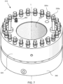
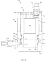
- FIG. 10 there is illustrated in top plan view a hydraulic MJT 100 according to a first embodiment of the present invention.
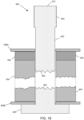
- FIG. 11 is a sectional view of the hydraulic MJT 100 through the lines B-B as indicated in FIG. 10
- FIG. 12 is an isometric view of the exterior of the hydraulic MJT.
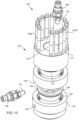
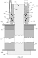
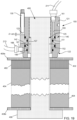
- Figures 13 to 15 comprise additional views of the hydraulic MJT 100 with hydraulic couplers installed for applying hydraulic pressure to pressure chambers of said MJT.
- the hydraulic MJT 100 is in the form of a nut style assembly and generally comprises an annular body 120 with central axis "L" which comprises a first, upper body section or “nut body” 121 having a central circular threaded hole 125 formed therethrough to receive a stud or bolt (e.g. bolt 400 of Figures 16 to 19 ), and a second lower body section 122 that is spaced from the first section and includes a co-axial bore 126.
- the annular body 120 is formed with a concentric polar array of threaded jack bolt holes therethrough, arranged in two arcuate sub-arrays 123, 124 as shown in FIG. 10 . Through each of the threaded jack bolt holes there passes a corresponding one of a plurality of jack bolts 130a,...,130r (which may be generally referred to herein as simply "130" for brevity).
- the first, upper, body section 121 rests upon a first piston 140 which in the present embodiment comprises a load bearing member that, in use, can apply force to a workpiece to be fastened, such as a pipe flange for example.
- the first piston 140 is arranged in the present embodiment to apply force to a workpiece (e.g. flange 404 of Figures 16 to 19 ) via the second body section 122 disposed below in the annular body 120.
- the first piston 140 may apply the force to the workpiece via a further intermediate member such as a washer (e.g. washer 408a of Figures 16 to 19 ) or a yet further piston and/or body section.
- a further intermediate member such as a washer (e.g. washer 408a of Figures 16 to 19 ) or a yet further piston and/or body section.
- the first body section 121 and the first piston 140 are shaped so that the first piston 140 slides about a lower wall 127 of the first body section and cooperates therewith to define a first circumferential pressure chamber 151 therebetween, suitably annular in shape.
- the first pressure chamber 151 is in fluid communication via a fluid passage 165 provided in the first body section 121 with an external hydraulic port 161, shown closed by a removable plug 163 in FIG. 11 .
- the external port 161 may be positioned on the top outer periphery of the first body section 121 adjacent or proximate to at least one of the jack bolts 130.
- the first pressure chamber 151 is fluidically sealed by a hydraulic sealing arrangement, suitably including a combination of annular sealing ring 153 and retaining ring 155, provided at each of an inner location (denoted by suffix "i") and an outer location (denoted by suffix "o") between the first body section 121 first piston 140.
- the second, lower, body section 122 is arranged in axial abutment with and below an annular end surface of the first piston 140 and includes, in addition to the axial bore 126 which cooperates with piston skirt 148, an internal recess 128 for receiving a radially outwardly extending flange portion 144 of a second piston 142.
- a second fluid chamber 152 is provided in the body 120 between the second piston 142 and the second body section 122, suitably between opposed annular surfaces of the flange 144 and the internal recess 128, respectively.
- a fluid sealing arrangement is provided between second piston and second body section 122. The sealing arrangement is similar to that provided for the first pressure chamber including, for example, an outer retaining ring 154o and an associated outer sealing ring 156o.
- first and second hydraulic circuits are arranged in parallel for separate operation via ports feeding respective hydraulic chambers 151, 152. Separate hydraulic circuits are desirable for providing for redundancy in some applications of the tensioner of the invention.
- FIGs 16 to 19 illustrate the pistons 140, 142 in different operational positions.
- FIG. 16 is a cross sectional side view of a bolt 400 with a shank 403 passing through first and second workpieces in the form of first and second flanges 402, 404 that are to be fastened together.
- a bearing surface of the head 406 of the bolt 400 abuts a washer 408b in this example.
- the washer 408b in turn abuts the outside of the second flange 404.
- the point 410 of the bolt 400 and the adjacent threaded length 405 of the shank 403 extends out through the second flange 402 for capture by the hydraulic MJT 100 as will be explained.
- a second washer 408a surrounds the shank 403 and rests on the outer (i.e. upper as shown in FIG. 16 ) surface of the first flange 402.
- the hydraulic MJT 100 here in the form of a "nut" is installed onto bolt 400 engaging the threaded portion 405 of the bolt with the internally threaded central hole 125 of the first body section 121 until the load bearing member in the form of first piston 140 abuts the second body section 122 which in turn seats against the washer 408a which is located on the upper, outer, side of flange 402.
- the jack bolts 130 are sufficiently withdrawn in holes 123 of first body portion 121 so that the points of the jack bolts 130 do not abut the upper surface of the first piston 140 so as not to exert force against the first piston 140.
- the first piston 140 and the first body section 121 are brought close together so that the volume of the first pressure chamber 151 is very small or zero.
- a suitable hydraulic line 211 is applied to the first hydraulic port 161 using a hydraulic nipple 167 and coupler 168.
- the hydraulic line 211 is coupled to a source of hydraulic power.
- the first hydraulic chamber 151 expands in response to the hydraulic fluid thereby forcing the piston 140 apart from the first body section 121 to a separation distance D and thereby tensioning the bolt 400.
- the underside of the load bearing member which in the present example comprises second body section 122, bears down upon the outside, i.e. the topside as shown in FIG. 18 , of the workpiece in the form of flange 402 via washer 408a (an any other intermediate members that may be needed for a particular fastening situation).
- FIG. 18 depicts the second piston 142 in a neutral, unpressurized, position wherein the outwardly extending flange 144 rests upon an opposing annular surface of the recess 128.
- the annular surface has an opening in fluid communication with the second chamber 152 that is supplied with hydraulic pressure via passage 166 in use.
- a further hydraulic line 213, suitably providing a separately controlled flow of hydraulic fluid is applied to the second port 162 via a nipple 167 and coupler 168 for application of hydraulic pressure to second chamber 152 through passage 166.
- second piston 142 forces the second piston 142 apart from the second body portion 122 until the piston abuts an external annular surface of the first body section 121, in the embodiment an upper surface of second piston 142 abuts a lower surface of the depending skirt portion 127 of the first body section 121.
- first piston 140 which comprises the load bearing member
- the jack bolts 130 are each rotated sufficiently to bring their points firmly against the load bearing member, which in the present embodiment comprises first piston 140. It is not essential to perform this step on the jack bolts 130 in any particular order because evenly distributed loading between the first body section 121 and the piston 140 has already been achieved by virtue of the application of the hydraulic pressure.
- the separation of the first section 121 and the piston 140 results in the generation of an axial load when the hydraulic MJT 100 is mounted to the bolt 400 and the pressure chambers 151 and 152 receive hydraulic fluid.
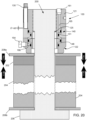
- the tensioning of the bolt 400 results in compression and/or tightening of the work pieces, e.g. flanges 402 and 404 that are being joined. In the present example illustrated in FIG. 20 , this means that the first and second flanges 402 and 404 are tightly compressed together as indicated by arrows 113a, 113b and 114a and 114b.
- This initial hydraulic pressurization step closes the joint between flanges 402 and 404 quickly.
- Multiple hydraulic MJTs like MJT 100 may be hydraulically operated simultaneously and from the same source of hydraulic power thereby ensuring uniform, simultaneous joint closure.
- the jack bolts 130 may be further tightened to a desired torque setting (hereinafter "torqued"), for example with a torque wrench, thereby adjusting the distance between the first piston 140 and the body 121 to thereby apply a precise final preload to the bolt or stud.
- torqued a desired torque setting
- FIG. 21 illustrates a corresponding "bolt-style" embodiment of a hydraulic MJT fastener 110A' having a body 120, including a first body section 121' with an integral bolt shaft portion 129.
- a gap (not shown) may be created between the first body section 121' and first piston 140 when first pressure chamber 151 receives hydraulic fluid via first port 161 to generate the pre-load in the bolt form section 121'.
- first pressure chamber 151 receives hydraulic fluid via first port 161 to generate the pre-load in the bolt form section 121'.
- the piston 140 Upon application of hydraulic pressure to the first port the piston 140, which in this embodiment bears against a second body section 122 that comprises the load bearing member against a workpiece, and the first body section 121' move apart.
- second piston 142 moves away from the second body portion 122, and engages with an undersurface 127' of the first body section 121' which the piston 142 has moved toward, i.e. upwardly as depicted in FIG. 21 .
- clearance space 141 is provided between an upper fustoconical face of the second piston 142 and a lower frustoconical face of the first piston 140 in the present embodiment
- the array of jack bolts 130 is subsequently tightened and the hydraulic pressure may be released to transfer the pre-load to the locking collar 70.
- the jack bolts 130 can then be torqued to further tension the elongate fastener, e.g. bolt 121' having shaft portion 129. Accordingly, the hydraulic pressure may be removed as soon as the jack bolts 130 have been tightened and prior to further torqueing the jack bolts 130.
- the hydraulic MJTs 110A' may comprise an upper locking collar (not shown).
- the body 120 may suitably be provided with an outside thread to threadingly engage such a locking collar.
- a hydraulic MJT which includes two (or more) hydraulic chambers, preferably axially displaced, in parallel, rather than a single chamber
- embodiments of the present invention may have a smaller diameter and thus be more compact than hitherto known and thus able to be used where space is at a premium, whilst still being able to provide comparable tensioning forces and also allowing for some redundancy in tensioning the elongate fastening member.
- a component means one or more components, and thus, possibly, more than one component is contemplated and may be employed or used in an implementation of the described embodiments.
- stud means tension elongated members, such as bolts, studs, and rods that may or may not comprise an integral head and/or threads.
- the integral head and/or threads may be configured to apply compression forces across a joint to produce a tension load in the stud.
- the threads may be configured for threaded connection with the hydraulic compression tool.
- the hydraulic MJT tool and components thereof may be made from any appropriate material and may have any size required for a particular application using materials and stress calculations known in the art.
- the body may comprise metal, such as steel, the pressure chamber may comprise a polymer, and the washer may comprise brass or aluminum.
- the body has a polar array of jack bolts spaced uniformly from a longitudinal central axis at spaced apart locations about an outer surface thereof.
- the body may comprise an annular recess for receiving a stud.
- the annular recess may comprise threads formed on its inside surface for threaded engagement with the stud.
- the annular recess may lack threads on its inside surface for engagement with the stud by compression fit.
- the body may comprise a threaded shaft to engage a hole, such as a threaded hole and a blind hole, in the work piece(s).
- the body may comprise drilled and tapped holes to threadedly engage each jack bolt.
- the jack bolt may comprise a socket-head cap screw.
- a person having ordinary skill in the art may appreciate that the number of jack bolts may be selected according to the desired stress that is to be imposed on the shank portion of the fastener.
- the jack bolts may be arranged in only one annular array but two or more annular arrays may be used to accommodate the desired number of jack bolts.
- the tool may comprise twenty-four jack bolts with twelve jack bolts spaced about each of the bolt centers in an alternating arrangement.
- the jack bolt may extend through a tapped hole and project from the body into engagement with a support surface.
- An end face of the jack bolt may extend into compressive engagement with a support surface.
- the support surface may comprise the piston, a load cell, or a washer.
- the support surface may comprise a flange portion of the piston.
- the washer may be constructed from material having a hardness predetermined according to the forces required to support the tool.
- the washer may be made from sufficiently hard material, such as metal or plastic, so that the washer may sustain the load imposed thereon by the jack bolt without yielding under the imposed load.
- the washer may be made from a sufficiently soft material so that the end face of the jack bolt is not upset under the applied load.
- the jack bolts may be used to mechanically retain the axial load generated by the hydraulic pressure.
- the jack bolts may be torqued until the end surface firmly contacts the support surface.
- Each jack bolt may be rotated until the end face extends from the body to contact the support surface.
- the jack bolts may be torqued in a patterned sequence such as, for example, by torqueing jacks bolts at opposite sides of the body and then advancing to an adjacent jack bolt.
- a lubricant, such as graphite may be applied to the threads of the jack bolt to facilitate torqueing thereof.
- the hydraulic MJT may comprise a sealing device (not shown), such as a gasket, to substantially fluidly seal the pressure chamber so that hydraulic pressure may be generated.
- the sealing device may seal any gap between the body and piston.
- the pressure chamber may be defined by the body, the piston, fluid passage, and sealing device.
- the tool may comprise one or more ports for each hydraulic circuit.
- the port/s may be located on a top surface of the body or piston, such as adjacent or proximate to at least one of the jack bolts, or on a side surface of the body section or piston.
- the port may comprise a standard threaded connection port to permit hydraulic fluid to be supplied to the pressure chamber at elevated pressure and vented therefrom.
- the port may comprise a one-way valve that threadedly engages the body and/or fluid passage. The one-way valve may prevent or reduce backflow when the pressure source is disconnected from the port.
- the pressure source may comprise a high-pressure hand pump that is manually operated.
- the body may comprise an opening configured to allow the insertion of a threading tool, such as a tommy bar (not shown), to assist the tensioning of the work piece(s).
- a threading tool such as a tommy bar (not shown)
- the opening may be positioned on the top and/or side outer periphery of the body.
- a locking collar or shim may be used to mechanically retain the axial load generated by the hydraulic pressure.
- the locking collar may be torqued while under hydraulic pressure until a face of the locking collar firmly contacts an opposing face of the body and/or piston.
- the shim may be inserted in the gap between opposing faces of the body and piston that is generated by the hydraulic force. When the hydraulic pressure is released, the load is transferred onto the shims or locking collar to retain the load.
- the locking collar may comprise one of a lower collar type and an upper collar type.
- the hydraulic MJT may comprise a lower locking collar including a piston having internal threads and external threads.
- the hydraulic MJT may comprise an upper locking collar including a piston having internal threads and external threads.
- the external threads of the piston may engage mating threads of the locking collar.
- a gap between the body and locking collar may be created when the pressure chamber receives hydraulic fluid to generate the pre-load.
- the width of the gap may generally relate to the compression of the joint, gasket, if fitted, and the elongation of the stud.
- the locking collar may be tightened and the pressure may be released to transfer the preload to the locking collar.
- the hydraulic MJT may comprise an upper locking collar including a plain bore load cell and a collar nut.
- the collar nut may comprise internal threads and external threads. The external threads may engage mating threads of the locking collar.
- a gap between the body and locking collar may be created when the pressure chamber receives hydraulic fluid to generate the pre-load.
- the width of the gap may generally relate to the compression of the joint, gasket, if fitted, and the elongation of the stud.
- the locking collar may be tightened and the pressure may be released to transfer the preload to the locking collar.
- the port may be positioned on the side of the piston because the load cell has a plain bore.
- the hydraulic MJT may comprise a shim, and the piston may comprise a flanged piston.
- a shim gap may be created when the pressure chamber receives hydraulic fluid to generate the pre-load.
- the width of the gap may generally relate to the compression of the joint, gasket, if fitted, and the elongation of the stud.
- the width of the shim gap may be measured and a shim having the desired width may be inserted into the shim gap.
- the shim may comprise one or more shims such that the shims completely fill the shim gap.
- Each shim may be configured to couple to at least a portion of the jack bolts.
- a method of closing a vessel having a plurality of studs may generally comprise threading a hydraulic nut or hydraulic MJT onto at least one of the plurality of studs of the vessel, and injecting hydraulic fluid into at least one of the chambers of the hydraulic nut and/or hydraulic MJT to tension at least one stud.
- the method may comprise threading a hydraulic MJT onto three bolts of the vessel that are spaced 120 degrees apart, and injecting hydraulic fluid into the chamber of each of the or hydraulic compression tools to tension each of the three bolts.
- MJTs may be positioned adjacent to each of the hydraulic compression tools and tightened to the desired preload.
- the plurality of jack bolts on each of the hydraulic compression tools may be tightened to the desired preload, and the hydraulic pressure may be released.
- the hydraulic pressure may be released and the hydraulic compression tools may be replaced by MJTs that are then tightened to the desired preload.
- the method may also include applying hydraulic compression tools to all of the studs and linking them with hoses to perform a single pass hydraulic closure.
- the method may comprise threading a hydraulic MJT onto each of the bolts of the vessel, wherein each of the hydraulic compression tools are in fluid communication with each other, and injecting hydraulic fluid into a chamber of each of the hydraulic compression tools to tension each of the bolts substantially simultaneously to the same preload.
- the load generated by the hydraulic compression tools may be evenly distributed around the joint such that a compression gasket may flow into any surface irregularities of the vessel to provide an improved seal relative to tightening the bolts individually.
- the plurality of jack bolts on each of the hydraulic compression tools may be tightened to the desired preload, and the hydraulic pressure may be released.
- the method may comprise torqueing the hydraulic MJT onto a bolt of the vessel relatively low torque level prior to introducing hydraulic fluid to the port.
- the hydraulic MJT may be threaded onto the bolt until the hydraulic MJT contacts the surface of the vessel.
- a hydraulic pumping unit may deliver hydraulic fluid, such as high-pressure oil, into the pressure chamber of the hydraulic compression tool.
- hydraulic fluid such as high-pressure oil
- the pressure supply may be stopped to release the hydraulic pressure.
- the provision of multiple hydraulic chambers in the tool of the embodiment provides for redundancy in the sense that, should a hydraulic seal fail in one of the chambers, the tensioning process can still proceed using the remaining chamber/s albeit at reduced load capacity.
- the reduced capacity can be at least partially overcome by modifying the tightening regime utilizing the array of jack bolts.
- all jack bolts engage with the first piston.
- the second polar array may be provided in either an outer concentric arrangement, with enlarged diameter body sections, or around the body in alternating fashion with individual jack bolts of the first array in other applications.
Landscapes
- Engineering & Computer Science (AREA)
- General Engineering & Computer Science (AREA)
- Mechanical Engineering (AREA)
- Hand Tools For Fitting Together And Separating, Or Other Hand Tools (AREA)
- Actuator (AREA)
Claims (12)
- Mehrschrauben-Spannvorrichtung (100) zum Aufbringen von Spannung auf ein Befestigungsmittel, die Spannvorrichtung umfassend:einen Körper (120) mit mindestens einem Abschnitt, der einen ersten Körperabschnitt (121) einschließt, der ausgebildet ist, um in ein längliches Befestigungselement einzugreifen oder der einstückig damit ausgebildet ist;ein Trageelement (140) zum Aufbringen von Kraft auf ein Werkstück, das befestigt und angeordnet werden soll, um um das Befestigungselement angrenzend an den Körper (120) positioniert zu sein;mindestens eine voneiner Mehrzahl von Druckkammern (151, 152) zwischen dem Trageelement (140) und dem Körper (120), die angeordnet ist, um den mindestens einen Körperabschnitt als Reaktion auf einen Hydraulikdruck axial relativ zu dem Trageelement (140) zu verschieben; undeiner Mehrzahl von Nivellierschrauben (130a...130r), die sich zwischen dem ersten Körperabschnitt (121) und dem Trageelement (140) erstreckt, um den ersten Körperabschnitt (121) von dem Trageelement weiter zu verschieben;wobei das Aufbringen von Hydraulikdruck auf eine oder mehrere der Mehrzahl von Druckkammern (151, 152) den ersten Körperabschnitt (121) von dem Trageelement (140) verschiebt, wobei dadurch das Befestigungselement gespannt wird und wodurch das anschließende Spannen des Befestigungselements durch ein Betätigen der Nivellierschrauben (130a....130r) erreicht wird.
- Mehrschrauben-Spannvorrichtung (100) nach Anspruch 1, wobei eine erste Druckkammer (151) der Mehrzahl von Kammern (151, 152) durch eine Oberfläche des ersten Körperabschnitts (121) und eine Oberfläche des Trageelements (140) definiert ist, wodurch ein Einleiten von Hydraulikdruck in die erste Druckkammer (151) den ersten Körperabschnitt (121) von dem Trageelement (140) verschiebt.
- Mehrschrauben-Spannvorrichtung (100) nach Anspruch 1 oder 2, wobei der mindestens eine Abschnitt des Körpers (120) einen zweiten Körperabschnitt (122) einschließt und wobei eine zweite Druckkammer (152) der Mehrzahl von Kammern (151, 152) zwischen einer Oberfläche des zweiten Körperabschnitts (122) und einer Oberfläche eines Kolbens (142) definiert ist, der in eine Öffnung des zweiten Körperabschnitts (122) gleitet, wodurch das Einleiten von Hydraulikdruck in die zweite Druckkammer (152) den Kolben (142) relativ zu dem zweiten Körperabschnitt (122) des Körpers (120) verschiebt.
- Mehrschrauben-Spannvorrichtung (100) nach Anspruch 3, wobei der erste Körperabschnitt (121) einen Abschnitt (127) einschließt, der sich in die Öffnung des zweiten Körperabschnitts (122) erstreckt, der durch den Kolben (142) bei dem Einleiten des Hydraulikdrucks in die zweite Druckkammer (152) von dem zweiten Körperabschnitt (122) weggedrückt wird, um dadurch den ersten Körperabschnitt (121) von dem Trageelement (140) zu verschieben.
- Mehrschrauben-Spannvorrichtung (100) nach Anspruch 4, wobei das Tragelement (140) axial zwischen dem ersten Körperabschnitt (121) und dem zweiten Körperabschnitt (122) angeordnet ist.
- Mehrschrauben-Spannvorrichtung (100) nach Anspruch 4 oder 5, wobei der Abschnitt (127), der sich in die Öffnung des zweiten Körperabschnitts (122) erstreckt, eine untere Schürze umfasst und wobei die erste Druckkammer (151) zwischen dem Trageelement (140) und dem ersten Körperabschnitt (121) angrenzend an die untere Schürze definiert ist.
- Mehrschrauben-Spannvorrichtung (100) nach einem der vorstehenden Ansprüche, wobei das Tragelement (140) als ein Kolben ausgebildet ist, der angeordnet ist, um mit dem Körper (120) zusammenzuwirken.
- Mehrschrauben-Spannvorrichtung (100) nach einem der vorstehenden Ansprüche, wobei der Körper (120) mit einem sich axial erstreckenden zentralen Loch (125) ausgebildet ist, wobei der erste Körperabschnitt (121) davon angeordnet ist, um mit dem länglichen Befestigungselement in Eingriff zu kommen, wobei das längliche Befestigungselement eine Schraube oder einen Bolzen (400) umfasst.
- Mehrschrauben-Spannvorrichtung (100) nach einem der Ansprüche 1 bis 7, wobei der Körper (120) einstückig mit dem länglichen Befestigungselement ausgebildet ist.
- Mehrschrauben-Spannvorrichtung (100) nach einem der Ansprüche 3 bis 6, der einen ersten und einen zweiten hydraulischen Fluidanschluss (161, 162) in Fluidverbindung mit der ersten und der zweiten Druckkammer (151, 152) einschließt.
- Mehrschrauben-Spannvorrichtung (100) nach Anspruch 10, wobei sich der erste und der zweite hydraulische Fluidanschluss (161, 162) von dem Körper (120) in rechten Winkeln zueinander erstrecken.
- Verfahren zum Zusammenpressen von ersten und zweiten Werkstücken, umfassend die folgenden Schritte:Positionieren eines länglichen Befestigungselements über das erste und das zweite Werkstück, wobei ein erstes Ende des länglichen Befestigungselements an dem ersten Werkstück befestigt ist;Spannen des länglichen Befestigungselements durch das Aufbringen von Hydraulikdruck auf eine oder mehrere einer Mehrzahl von Druckkammern (151, 152), die axial entlang des länglichen Befestigungselements beabstandet sind und zwischen dem zweiten Ende des Befestigungselements und einer Außenseite des zweiten Werkstücks angeordnet sind; undweiteres Spannen des länglichen Elements mit einer Mehrzahl von Nivellierschrauben (130a.... 130r);wodurch das Spannen des länglichen Befestigungselements dazu führt, dass das erste und das zweite Werkstück zueinander zusammengepresst werden.
Applications Claiming Priority (2)
| Application Number | Priority Date | Filing Date | Title |
|---|---|---|---|
| US201762607978P | 2017-12-20 | 2017-12-20 | |
| PCT/US2018/066669 WO2019126426A1 (en) | 2017-12-20 | 2018-12-20 | Multiple chamber hydraulic multi-jack bolt tensioners |
Publications (3)
| Publication Number | Publication Date |
|---|---|
| EP3728876A1 EP3728876A1 (de) | 2020-10-28 |
| EP3728876A4 EP3728876A4 (de) | 2021-01-20 |
| EP3728876B1 true EP3728876B1 (de) | 2023-05-17 |
Family
ID=66993857
Family Applications (1)
| Application Number | Title | Priority Date | Filing Date |
|---|---|---|---|
| EP18892720.6A Active EP3728876B1 (de) | 2017-12-20 | 2018-12-20 | Hydraulische mehrkammer-mehrschrauben-spannvorrichtungen |
Country Status (6)
| Country | Link |
|---|---|
| US (1) | US11285573B2 (de) |
| EP (1) | EP3728876B1 (de) |
| CN (1) | CN111656025B (de) |
| AU (1) | AU2018393082B2 (de) |
| DK (1) | DK3728876T3 (de) |
| WO (1) | WO2019126426A1 (de) |
Families Citing this family (7)
| Publication number | Priority date | Publication date | Assignee | Title |
|---|---|---|---|---|
| WO2019089794A1 (en) * | 2017-11-01 | 2019-05-09 | Cetres Holdings, Llc | Hydraulic expandable connector |
| US12044264B2 (en) | 2020-07-21 | 2024-07-23 | Nord-Lock Switzerland Gmbh | Method and apparatus for fastening in a high fluid pressure environment |
| US12350774B2 (en) | 2020-07-21 | 2025-07-08 | Nord-Lock Switzerland Gmbh | Method and apparatus for fastening in a high fluid pressure environment |
| GB202017991D0 (en) * | 2020-11-16 | 2020-12-30 | Acutension Ltd | Improved bolt tensioner |
| US11389916B1 (en) | 2021-09-23 | 2022-07-19 | Caterpillar Inc. | Systems and methods for assembling or disassembling a hammer tool |
| US11946501B2 (en) * | 2021-09-23 | 2024-04-02 | Caterpillar Inc. | Systems and methods for assembling a hammer tool |
| USD1015863S1 (en) * | 2022-05-20 | 2024-02-27 | Nord-Lock Switzerland Gmbh | Fastening device |
Family Cites Families (43)
| Publication number | Priority date | Publication date | Assignee | Title |
|---|---|---|---|---|
| US3154006A (en) * | 1962-10-12 | 1964-10-27 | Danly Mach Specialties Inc | Tensioning system for power press tie rods |
| GB1115457A (en) * | 1965-11-08 | 1968-05-29 | P & O Res & Dev Co | Improvements in propeller fastening |
| US3424080A (en) * | 1967-08-23 | 1969-01-28 | Lambros A Pappas | Hydraulic tie rod nut |
| US3722332A (en) * | 1971-06-01 | 1973-03-27 | Transfer Systems | Apparatus for securing the bolts of the reactor pressure vessel head to the reactor pressure vessel |
| DE2258859A1 (de) * | 1972-12-01 | 1974-06-12 | Masch Und Bohrgeraete Fabrik | Hydraulische spannvorrichtung |
| US4182215A (en) * | 1978-05-30 | 1980-01-08 | Terra Tek, Inc. | Failsafe hydraulic prestressing nut |
| US4338037A (en) * | 1980-08-08 | 1982-07-06 | The Yorde Machine Products Company | Multiple jackscrew rod to crosshead mounting |
| US4438901A (en) * | 1982-01-25 | 1984-03-27 | Gripper, Inc. | Apparatus for tensioning a stud and method of doing same |
| SE454340B (sv) * | 1982-09-20 | 1988-04-25 | Mac Lean Fogg Co | Fastsettningsanordning for fastspenda hjul |
| US4622730A (en) * | 1984-03-30 | 1986-11-18 | Rolf Steinbock | Apparatus to mechanically stress a bolt-type fastener |
| USRE33490E (en) | 1984-03-30 | 1990-12-18 | Apparatus to mechanically stress a bolt-type fastener | |
| FR2582047B1 (fr) * | 1985-05-17 | 1988-04-08 | Inst Francais Du Petrole | Dispositif d'assemblage a distance de deux organes |
| US4844418A (en) * | 1987-03-02 | 1989-07-04 | Westinghouse Electric Corp. | Short stud tensioning apparatus |
| US4854798A (en) * | 1987-05-29 | 1989-08-08 | Westinghouse Electric Corp. | In-place tensioning washer |
| JPH03500268A (ja) * | 1987-09-29 | 1991-01-24 | バックネル,ジョン ウエントウァース | 加力装置 |
| US4846444A (en) * | 1988-07-05 | 1989-07-11 | Michael Vassalotti | Stud tensioning and tighetning apparatus |
| US4927305A (en) | 1988-09-02 | 1990-05-22 | Peterson Charles D | Tightening device for threaded connectors |
| GB8823474D0 (en) * | 1988-10-06 | 1988-11-16 | Hedley Purvis Ltd | Improved hydraulic tensioner |
| US5075950A (en) | 1990-06-28 | 1991-12-31 | Steinbock Rolf H | Method for loosening jack bolts |
| US5083889A (en) | 1990-10-04 | 1992-01-28 | Steinbock Rolf H | Structure for preventing escape of jack bolts in apparatus to mechanically stress a bolt-type fastener |
| WO1993005306A1 (en) * | 1991-09-02 | 1993-03-18 | Pilgrim Moorside Limited | Improvements in and relating to fasteners |
| US5285722A (en) * | 1992-11-16 | 1994-02-15 | The Minster Machine Company | Press shutheight adjustment using hydraulic tie rod assemblies |
| GB2274893B (en) * | 1993-02-05 | 1995-10-04 | Hydra Tight Ltd | Tensioning arrangement |
| UA45310C2 (uk) * | 1995-06-13 | 2002-04-15 | К. Юнкерс Джон | Гідравлічний пристрій натягування болтів |
| SE9502130L (sv) | 1995-06-13 | 1996-12-14 | Ovako Couplings Ab | Förspänning av casing-bultar |
| CN1143004A (zh) * | 1995-08-14 | 1997-02-19 | 约翰·K·琼克斯 | 用于伸长或放松螺纹连接器的液体致动工具 |
| US6199453B1 (en) * | 1998-04-28 | 2001-03-13 | Steinbock Machinery Co. | High temperature bolting system |
| AU4438299A (en) * | 1998-06-10 | 1999-12-30 | Steinbock Machinery Co. | Jackbolts for multi jackbolt tensioners |
| US6112396A (en) | 1998-06-10 | 2000-09-05 | Steinbock Machinery Co. | Jackbolts for multi jackbolt tensioners |
| AUPP890599A0 (en) * | 1999-02-26 | 1999-03-25 | Bucknell, John Wentworth | Tensioning hydraulic nuts |
| US6250216B1 (en) * | 1999-03-19 | 2001-06-26 | The Minster Machine Company | Press deflection controller and method of controlling press deflection |
| AU2002352942A1 (en) | 2001-11-30 | 2003-06-17 | Westinghouse Electric Company Llc | Method of closing a pressure vessel |
| FI116409B (fi) * | 2002-02-07 | 2005-11-15 | Metso Paper Inc | Kiristyselin |
| US6938450B1 (en) * | 2003-02-07 | 2005-09-06 | Dana Corporation | Double nut tensioner assembly for pre-stretched tie rods |
| AU2003231379B2 (en) * | 2003-02-10 | 2007-11-08 | Akira Imai | Liquid pressure device |
| EP1718877B1 (de) * | 2004-02-25 | 2011-07-27 | BUCKNELL, John Wentworth | Hydraulisch unterstützte befestigungselemente |
| WO2007043143A1 (ja) | 2005-10-05 | 2007-04-19 | Imai, Akira | 液体圧装置 |
| EP2199025A1 (de) * | 2008-12-18 | 2010-06-23 | SNR Roulements | Hydraulische Mutter |
| US9188146B1 (en) * | 2010-08-05 | 2015-11-17 | Riverhawk Company | Hydraulic rod tensioning system |
| FR3008147B1 (fr) | 2013-07-08 | 2015-08-07 | Beck Tight | Dispositif de serrage d'ecrou |
| DE102014219643A1 (de) * | 2014-05-12 | 2015-11-12 | Siemens Aktiengesellschaft | Ringförmige Spannmutter für einen Zuganker |
| FR3034821B1 (fr) * | 2015-04-09 | 2017-09-08 | Skf Ab | Dispositif de tension pour mise en precontrainte d'un assemblage au moyen d'une tige filetee |
| EP3093641B1 (de) * | 2015-05-11 | 2017-06-28 | Siemens Aktiengesellschaft | Verfahren zur bestimmung einer in ein bauteil eingebrachten axialen zugkraft |
-
2018
- 2018-12-20 DK DK18892720.6T patent/DK3728876T3/da active
- 2018-12-20 AU AU2018393082A patent/AU2018393082B2/en not_active Ceased
- 2018-12-20 CN CN201880086835.XA patent/CN111656025B/zh not_active Expired - Fee Related
- 2018-12-20 EP EP18892720.6A patent/EP3728876B1/de active Active
- 2018-12-20 US US16/956,501 patent/US11285573B2/en active Active
- 2018-12-20 WO PCT/US2018/066669 patent/WO2019126426A1/en not_active Ceased
Also Published As
| Publication number | Publication date |
|---|---|
| US20210008676A1 (en) | 2021-01-14 |
| US11285573B2 (en) | 2022-03-29 |
| EP3728876A4 (de) | 2021-01-20 |
| AU2018393082A1 (en) | 2020-07-16 |
| WO2019126426A1 (en) | 2019-06-27 |
| AU2018393082B2 (en) | 2024-03-14 |
| CN111656025A (zh) | 2020-09-11 |
| EP3728876A1 (de) | 2020-10-28 |
| DK3728876T3 (da) | 2023-06-12 |
| CN111656025B (zh) | 2022-02-11 |
Similar Documents
| Publication | Publication Date | Title |
|---|---|---|
| EP3728876B1 (de) | Hydraulische mehrkammer-mehrschrauben-spannvorrichtungen | |
| AU2017285427B2 (en) | Improvements to multi-jack tensioners | |
| US12152582B2 (en) | Fluid end assembly | |
| US20210095650A1 (en) | Multi-Piece Fluid End | |
| US12023766B2 (en) | Hydraulic tensioning and release tool for expansion fasteners | |
| WO2005108790A1 (en) | Valve cap | |
| EP1979630B1 (de) | Einteilige hydraulische mutter | |
| US20110192257A1 (en) | Hydraulic Bolt Tensioner and Nut | |
| CN104066555A (zh) | 一种张紧装置 | |
| US10195700B1 (en) | High pressure press with tensioning assembly and related methods | |
| US5393165A (en) | Anchor bolt repair coupling with preloading jack and epoxy injection | |
| NL2024795B1 (en) | Assembly comprising a first and a second member and a connector, and a method of assembling such an assembly | |
| CA3028270C (en) | Improvements to multi-jack bolt tensioners | |
| US12000501B2 (en) | Removably mounted actuator assembly | |
| US20240017386A1 (en) | Improved Bolt Tensioner |
Legal Events
| Date | Code | Title | Description |
|---|---|---|---|
| STAA | Information on the status of an ep patent application or granted ep patent |
Free format text: STATUS: THE INTERNATIONAL PUBLICATION HAS BEEN MADE |
|
| PUAI | Public reference made under article 153(3) epc to a published international application that has entered the european phase |
Free format text: ORIGINAL CODE: 0009012 |
|
| STAA | Information on the status of an ep patent application or granted ep patent |
Free format text: STATUS: REQUEST FOR EXAMINATION WAS MADE |
|
| 17P | Request for examination filed |
Effective date: 20200707 |
|
| AK | Designated contracting states |
Kind code of ref document: A1 Designated state(s): AL AT BE BG CH CY CZ DE DK EE ES FI FR GB GR HR HU IE IS IT LI LT LU LV MC MK MT NL NO PL PT RO RS SE SI SK SM TR |
|
| AX | Request for extension of the european patent |
Extension state: BA ME |
|
| A4 | Supplementary search report drawn up and despatched |
Effective date: 20201222 |
|
| RIC1 | Information provided on ipc code assigned before grant |
Ipc: F16B 31/04 20060101AFI20201216BHEP Ipc: F16B 1/00 20060101ALI20201216BHEP |
|
| DAV | Request for validation of the european patent (deleted) | ||
| DAX | Request for extension of the european patent (deleted) | ||
| GRAP | Despatch of communication of intention to grant a patent |
Free format text: ORIGINAL CODE: EPIDOSNIGR1 |
|
| STAA | Information on the status of an ep patent application or granted ep patent |
Free format text: STATUS: GRANT OF PATENT IS INTENDED |
|
| INTG | Intention to grant announced |
Effective date: 20221214 |
|
| GRAS | Grant fee paid |
Free format text: ORIGINAL CODE: EPIDOSNIGR3 |
|
| GRAA | (expected) grant |
Free format text: ORIGINAL CODE: 0009210 |
|
| STAA | Information on the status of an ep patent application or granted ep patent |
Free format text: STATUS: THE PATENT HAS BEEN GRANTED |
|
| AK | Designated contracting states |
Kind code of ref document: B1 Designated state(s): AL AT BE BG CH CY CZ DE DK EE ES FI FR GB GR HR HU IE IS IT LI LT LU LV MC MK MT NL NO PL PT RO RS SE SI SK SM TR |
|
| REG | Reference to a national code |
Ref country code: GB Ref legal event code: FG4D |
|
| REG | Reference to a national code |
Ref country code: DE Ref legal event code: R096 Ref document number: 602018050062 Country of ref document: DE |
|
| REG | Reference to a national code |
Ref country code: CH Ref legal event code: EP |
|
| REG | Reference to a national code |
Ref country code: IE Ref legal event code: FG4D |
|
| REG | Reference to a national code |
Ref country code: DK Ref legal event code: T3 Effective date: 20230609 |
|
| REG | Reference to a national code |
Ref country code: AT Ref legal event code: REF Ref document number: 1568478 Country of ref document: AT Kind code of ref document: T Effective date: 20230615 |
|
| P01 | Opt-out of the competence of the unified patent court (upc) registered |
Effective date: 20230518 |
|
| REG | Reference to a national code |
Ref country code: LT Ref legal event code: MG9D |
|
| REG | Reference to a national code |
Ref country code: NL Ref legal event code: MP Effective date: 20230517 |
|
| PG25 | Lapsed in a contracting state [announced via postgrant information from national office to epo] |
Ref country code: SE Free format text: LAPSE BECAUSE OF FAILURE TO SUBMIT A TRANSLATION OF THE DESCRIPTION OR TO PAY THE FEE WITHIN THE PRESCRIBED TIME-LIMIT Effective date: 20230517 Ref country code: PT Free format text: LAPSE BECAUSE OF FAILURE TO SUBMIT A TRANSLATION OF THE DESCRIPTION OR TO PAY THE FEE WITHIN THE PRESCRIBED TIME-LIMIT Effective date: 20230918 Ref country code: NO Free format text: LAPSE BECAUSE OF FAILURE TO SUBMIT A TRANSLATION OF THE DESCRIPTION OR TO PAY THE FEE WITHIN THE PRESCRIBED TIME-LIMIT Effective date: 20230817 Ref country code: NL Free format text: LAPSE BECAUSE OF FAILURE TO SUBMIT A TRANSLATION OF THE DESCRIPTION OR TO PAY THE FEE WITHIN THE PRESCRIBED TIME-LIMIT Effective date: 20230517 Ref country code: ES Free format text: LAPSE BECAUSE OF FAILURE TO SUBMIT A TRANSLATION OF THE DESCRIPTION OR TO PAY THE FEE WITHIN THE PRESCRIBED TIME-LIMIT Effective date: 20230517 |
|
| PG25 | Lapsed in a contracting state [announced via postgrant information from national office to epo] |
Ref country code: RS Free format text: LAPSE BECAUSE OF FAILURE TO SUBMIT A TRANSLATION OF THE DESCRIPTION OR TO PAY THE FEE WITHIN THE PRESCRIBED TIME-LIMIT Effective date: 20230517 Ref country code: PL Free format text: LAPSE BECAUSE OF FAILURE TO SUBMIT A TRANSLATION OF THE DESCRIPTION OR TO PAY THE FEE WITHIN THE PRESCRIBED TIME-LIMIT Effective date: 20230517 Ref country code: LV Free format text: LAPSE BECAUSE OF FAILURE TO SUBMIT A TRANSLATION OF THE DESCRIPTION OR TO PAY THE FEE WITHIN THE PRESCRIBED TIME-LIMIT Effective date: 20230517 Ref country code: LT Free format text: LAPSE BECAUSE OF FAILURE TO SUBMIT A TRANSLATION OF THE DESCRIPTION OR TO PAY THE FEE WITHIN THE PRESCRIBED TIME-LIMIT Effective date: 20230517 Ref country code: IS Free format text: LAPSE BECAUSE OF FAILURE TO SUBMIT A TRANSLATION OF THE DESCRIPTION OR TO PAY THE FEE WITHIN THE PRESCRIBED TIME-LIMIT Effective date: 20230917 Ref country code: HR Free format text: LAPSE BECAUSE OF FAILURE TO SUBMIT A TRANSLATION OF THE DESCRIPTION OR TO PAY THE FEE WITHIN THE PRESCRIBED TIME-LIMIT Effective date: 20230517 Ref country code: GR Free format text: LAPSE BECAUSE OF FAILURE TO SUBMIT A TRANSLATION OF THE DESCRIPTION OR TO PAY THE FEE WITHIN THE PRESCRIBED TIME-LIMIT Effective date: 20230818 |
|
| PGFP | Annual fee paid to national office [announced via postgrant information from national office to epo] |
Ref country code: FR Payment date: 20230927 Year of fee payment: 6 |
|
| PG25 | Lapsed in a contracting state [announced via postgrant information from national office to epo] |
Ref country code: FI Free format text: LAPSE BECAUSE OF FAILURE TO SUBMIT A TRANSLATION OF THE DESCRIPTION OR TO PAY THE FEE WITHIN THE PRESCRIBED TIME-LIMIT Effective date: 20230517 |
|
| PG25 | Lapsed in a contracting state [announced via postgrant information from national office to epo] |
Ref country code: SK Free format text: LAPSE BECAUSE OF FAILURE TO SUBMIT A TRANSLATION OF THE DESCRIPTION OR TO PAY THE FEE WITHIN THE PRESCRIBED TIME-LIMIT Effective date: 20230517 |
|
| PGFP | Annual fee paid to national office [announced via postgrant information from national office to epo] |
Ref country code: GB Payment date: 20231012 Year of fee payment: 6 |
|
| PG25 | Lapsed in a contracting state [announced via postgrant information from national office to epo] |
Ref country code: SM Free format text: LAPSE BECAUSE OF FAILURE TO SUBMIT A TRANSLATION OF THE DESCRIPTION OR TO PAY THE FEE WITHIN THE PRESCRIBED TIME-LIMIT Effective date: 20230517 Ref country code: SK Free format text: LAPSE BECAUSE OF FAILURE TO SUBMIT A TRANSLATION OF THE DESCRIPTION OR TO PAY THE FEE WITHIN THE PRESCRIBED TIME-LIMIT Effective date: 20230517 Ref country code: RO Free format text: LAPSE BECAUSE OF FAILURE TO SUBMIT A TRANSLATION OF THE DESCRIPTION OR TO PAY THE FEE WITHIN THE PRESCRIBED TIME-LIMIT Effective date: 20230517 Ref country code: EE Free format text: LAPSE BECAUSE OF FAILURE TO SUBMIT A TRANSLATION OF THE DESCRIPTION OR TO PAY THE FEE WITHIN THE PRESCRIBED TIME-LIMIT Effective date: 20230517 Ref country code: CZ Free format text: LAPSE BECAUSE OF FAILURE TO SUBMIT A TRANSLATION OF THE DESCRIPTION OR TO PAY THE FEE WITHIN THE PRESCRIBED TIME-LIMIT Effective date: 20230517 |
|
| PGFP | Annual fee paid to national office [announced via postgrant information from national office to epo] |
Ref country code: IT Payment date: 20231011 Year of fee payment: 6 Ref country code: DK Payment date: 20231015 Year of fee payment: 6 Ref country code: DE Payment date: 20230719 Year of fee payment: 6 Ref country code: AT Payment date: 20231012 Year of fee payment: 6 |
|
| REG | Reference to a national code |
Ref country code: DE Ref legal event code: R097 Ref document number: 602018050062 Country of ref document: DE |
|
| PLBE | No opposition filed within time limit |
Free format text: ORIGINAL CODE: 0009261 |
|
| STAA | Information on the status of an ep patent application or granted ep patent |
Free format text: STATUS: NO OPPOSITION FILED WITHIN TIME LIMIT |
|
| 26N | No opposition filed |
Effective date: 20240220 |
|
| PG25 | Lapsed in a contracting state [announced via postgrant information from national office to epo] |
Ref country code: SI Free format text: LAPSE BECAUSE OF FAILURE TO SUBMIT A TRANSLATION OF THE DESCRIPTION OR TO PAY THE FEE WITHIN THE PRESCRIBED TIME-LIMIT Effective date: 20230517 |
|
| PG25 | Lapsed in a contracting state [announced via postgrant information from national office to epo] |
Ref country code: SI Free format text: LAPSE BECAUSE OF FAILURE TO SUBMIT A TRANSLATION OF THE DESCRIPTION OR TO PAY THE FEE WITHIN THE PRESCRIBED TIME-LIMIT Effective date: 20230517 |
|
| PGFP | Annual fee paid to national office [announced via postgrant information from national office to epo] |
Ref country code: CH Payment date: 20240425 Year of fee payment: 6 |
|
| PG25 | Lapsed in a contracting state [announced via postgrant information from national office to epo] |
Ref country code: LU Free format text: LAPSE BECAUSE OF NON-PAYMENT OF DUE FEES Effective date: 20231220 |
|
| PG25 | Lapsed in a contracting state [announced via postgrant information from national office to epo] |
Ref country code: MC Free format text: LAPSE BECAUSE OF FAILURE TO SUBMIT A TRANSLATION OF THE DESCRIPTION OR TO PAY THE FEE WITHIN THE PRESCRIBED TIME-LIMIT Effective date: 20230517 |
|
| REG | Reference to a national code |
Ref country code: BE Ref legal event code: MM Effective date: 20231231 |
|
| PG25 | Lapsed in a contracting state [announced via postgrant information from national office to epo] |
Ref country code: MC Free format text: LAPSE BECAUSE OF FAILURE TO SUBMIT A TRANSLATION OF THE DESCRIPTION OR TO PAY THE FEE WITHIN THE PRESCRIBED TIME-LIMIT Effective date: 20230517 Ref country code: LU Free format text: LAPSE BECAUSE OF NON-PAYMENT OF DUE FEES Effective date: 20231220 |
|
| REG | Reference to a national code |
Ref country code: IE Ref legal event code: MM4A |
|
| PG25 | Lapsed in a contracting state [announced via postgrant information from national office to epo] |
Ref country code: IE Free format text: LAPSE BECAUSE OF NON-PAYMENT OF DUE FEES Effective date: 20231220 |
|
| PG25 | Lapsed in a contracting state [announced via postgrant information from national office to epo] |
Ref country code: BE Free format text: LAPSE BECAUSE OF NON-PAYMENT OF DUE FEES Effective date: 20231231 |
|
| PG25 | Lapsed in a contracting state [announced via postgrant information from national office to epo] |
Ref country code: IE Free format text: LAPSE BECAUSE OF NON-PAYMENT OF DUE FEES Effective date: 20231220 Ref country code: BE Free format text: LAPSE BECAUSE OF NON-PAYMENT OF DUE FEES Effective date: 20231231 |
|
| PG25 | Lapsed in a contracting state [announced via postgrant information from national office to epo] |
Ref country code: BG Free format text: LAPSE BECAUSE OF FAILURE TO SUBMIT A TRANSLATION OF THE DESCRIPTION OR TO PAY THE FEE WITHIN THE PRESCRIBED TIME-LIMIT Effective date: 20230517 |
|
| PG25 | Lapsed in a contracting state [announced via postgrant information from national office to epo] |
Ref country code: BG Free format text: LAPSE BECAUSE OF FAILURE TO SUBMIT A TRANSLATION OF THE DESCRIPTION OR TO PAY THE FEE WITHIN THE PRESCRIBED TIME-LIMIT Effective date: 20230517 |
|
| REG | Reference to a national code |
Ref country code: DE Ref legal event code: R119 Ref document number: 602018050062 Country of ref document: DE |
|
| REG | Reference to a national code |
Ref country code: DK Ref legal event code: EBP Effective date: 20241231 |
|
| PG25 | Lapsed in a contracting state [announced via postgrant information from national office to epo] |
Ref country code: CY Free format text: LAPSE BECAUSE OF FAILURE TO SUBMIT A TRANSLATION OF THE DESCRIPTION OR TO PAY THE FEE WITHIN THE PRESCRIBED TIME-LIMIT; INVALID AB INITIO Effective date: 20181220 |
|
| REG | Reference to a national code |
Ref country code: CH Ref legal event code: PL |
|
| REG | Reference to a national code |
Ref country code: AT Ref legal event code: MM01 Ref document number: 1568478 Country of ref document: AT Kind code of ref document: T Effective date: 20241220 |
|
| PG25 | Lapsed in a contracting state [announced via postgrant information from national office to epo] |
Ref country code: HU Free format text: LAPSE BECAUSE OF FAILURE TO SUBMIT A TRANSLATION OF THE DESCRIPTION OR TO PAY THE FEE WITHIN THE PRESCRIBED TIME-LIMIT; INVALID AB INITIO Effective date: 20181220 |
|
| GBPC | Gb: european patent ceased through non-payment of renewal fee |
Effective date: 20241220 |
|
| PG25 | Lapsed in a contracting state [announced via postgrant information from national office to epo] |
Ref country code: DE Free format text: LAPSE BECAUSE OF NON-PAYMENT OF DUE FEES Effective date: 20250701 |
|
| PG25 | Lapsed in a contracting state [announced via postgrant information from national office to epo] |
Ref country code: IT Free format text: LAPSE BECAUSE OF NON-PAYMENT OF DUE FEES Effective date: 20241220 |
|
| PG25 | Lapsed in a contracting state [announced via postgrant information from national office to epo] |
Ref country code: GB Free format text: LAPSE BECAUSE OF NON-PAYMENT OF DUE FEES Effective date: 20241220 |
|
| PG25 | Lapsed in a contracting state [announced via postgrant information from national office to epo] |
Ref country code: FR Free format text: LAPSE BECAUSE OF NON-PAYMENT OF DUE FEES Effective date: 20241231 Ref country code: AT Free format text: LAPSE BECAUSE OF NON-PAYMENT OF DUE FEES Effective date: 20241220 |
|
| PG25 | Lapsed in a contracting state [announced via postgrant information from national office to epo] |
Ref country code: CH Free format text: LAPSE BECAUSE OF NON-PAYMENT OF DUE FEES Effective date: 20241231 |
|
| PG25 | Lapsed in a contracting state [announced via postgrant information from national office to epo] |
Ref country code: TR Free format text: LAPSE BECAUSE OF FAILURE TO SUBMIT A TRANSLATION OF THE DESCRIPTION OR TO PAY THE FEE WITHIN THE PRESCRIBED TIME-LIMIT Effective date: 20230517 |