EP3728691B1 - Sol et dispositif et procédés associes - Google Patents
Sol et dispositif et procédés associes Download PDFInfo
- Publication number
- EP3728691B1 EP3728691B1 EP18833960.0A EP18833960A EP3728691B1 EP 3728691 B1 EP3728691 B1 EP 3728691B1 EP 18833960 A EP18833960 A EP 18833960A EP 3728691 B1 EP3728691 B1 EP 3728691B1
- Authority
- EP
- European Patent Office
- Prior art keywords
- relief
- ground surface
- ground
- substrate
- obtaining
- Prior art date
- Legal status (The legal status is an assumption and is not a legal conclusion. Google has not performed a legal analysis and makes no representation as to the accuracy of the status listed.)
- Active
Links
Images


Classifications
-
- B—PERFORMING OPERATIONS; TRANSPORTING
- B33—ADDITIVE MANUFACTURING TECHNOLOGY
- B33Y—ADDITIVE MANUFACTURING, i.e. MANUFACTURING OF THREE-DIMENSIONAL [3D] OBJECTS BY ADDITIVE DEPOSITION, ADDITIVE AGGLOMERATION OR ADDITIVE LAYERING, e.g. BY 3D PRINTING, STEREOLITHOGRAPHY OR SELECTIVE LASER SINTERING
- B33Y10/00—Processes of additive manufacturing
-
- B—PERFORMING OPERATIONS; TRANSPORTING
- B22—CASTING; POWDER METALLURGY
- B22F—WORKING METALLIC POWDER; MANUFACTURE OF ARTICLES FROM METALLIC POWDER; MAKING METALLIC POWDER; APPARATUS OR DEVICES SPECIALLY ADAPTED FOR METALLIC POWDER
- B22F10/00—Additive manufacturing of workpieces or articles from metallic powder
- B22F10/20—Direct sintering or melting
-
- B—PERFORMING OPERATIONS; TRANSPORTING
- B22—CASTING; POWDER METALLURGY
- B22F—WORKING METALLIC POWDER; MANUFACTURE OF ARTICLES FROM METALLIC POWDER; MAKING METALLIC POWDER; APPARATUS OR DEVICES SPECIALLY ADAPTED FOR METALLIC POWDER
- B22F10/00—Additive manufacturing of workpieces or articles from metallic powder
- B22F10/60—Treatment of workpieces or articles after build-up
- B22F10/62—Treatment of workpieces or articles after build-up by chemical means
-
- B—PERFORMING OPERATIONS; TRANSPORTING
- B22—CASTING; POWDER METALLURGY
- B22F—WORKING METALLIC POWDER; MANUFACTURE OF ARTICLES FROM METALLIC POWDER; MAKING METALLIC POWDER; APPARATUS OR DEVICES SPECIALLY ADAPTED FOR METALLIC POWDER
- B22F10/00—Additive manufacturing of workpieces or articles from metallic powder
- B22F10/60—Treatment of workpieces or articles after build-up
- B22F10/66—Treatment of workpieces or articles after build-up by mechanical means
-
- B—PERFORMING OPERATIONS; TRANSPORTING
- B22—CASTING; POWDER METALLURGY
- B22F—WORKING METALLIC POWDER; MANUFACTURE OF ARTICLES FROM METALLIC POWDER; MAKING METALLIC POWDER; APPARATUS OR DEVICES SPECIALLY ADAPTED FOR METALLIC POWDER
- B22F3/00—Manufacture of workpieces or articles from metallic powder characterised by the manner of compacting or sintering; Apparatus specially adapted therefor ; Presses and furnaces
- B22F3/24—After-treatment of workpieces or articles
-
- B—PERFORMING OPERATIONS; TRANSPORTING
- B23—MACHINE TOOLS; METAL-WORKING NOT OTHERWISE PROVIDED FOR
- B23K—SOLDERING OR UNSOLDERING; WELDING; CLADDING OR PLATING BY SOLDERING OR WELDING; CUTTING BY APPLYING HEAT LOCALLY, e.g. FLAME CUTTING; WORKING BY LASER BEAM
- B23K26/00—Working by laser beam, e.g. welding, cutting or boring
- B23K26/34—Laser welding for purposes other than joining
- B23K26/342—Build-up welding
-
- B—PERFORMING OPERATIONS; TRANSPORTING
- B23—MACHINE TOOLS; METAL-WORKING NOT OTHERWISE PROVIDED FOR
- B23K—SOLDERING OR UNSOLDERING; WELDING; CLADDING OR PLATING BY SOLDERING OR WELDING; CUTTING BY APPLYING HEAT LOCALLY, e.g. FLAME CUTTING; WORKING BY LASER BEAM
- B23K26/00—Working by laser beam, e.g. welding, cutting or boring
- B23K26/352—Working by laser beam, e.g. welding, cutting or boring for surface treatment
- B23K26/354—Working by laser beam, e.g. welding, cutting or boring for surface treatment by melting
-
- B—PERFORMING OPERATIONS; TRANSPORTING
- B28—WORKING CEMENT, CLAY, OR STONE
- B28B—SHAPING CLAY OR OTHER CERAMIC COMPOSITIONS; SHAPING SLAG; SHAPING MIXTURES CONTAINING CEMENTITIOUS MATERIAL, e.g. PLASTER
- B28B1/00—Producing shaped prefabricated articles from the material
- B28B1/001—Rapid manufacturing of 3D objects by additive depositing, agglomerating or laminating of material
-
- B—PERFORMING OPERATIONS; TRANSPORTING
- B33—ADDITIVE MANUFACTURING TECHNOLOGY
- B33Y—ADDITIVE MANUFACTURING, i.e. MANUFACTURING OF THREE-DIMENSIONAL [3D] OBJECTS BY ADDITIVE DEPOSITION, ADDITIVE AGGLOMERATION OR ADDITIVE LAYERING, e.g. BY 3D PRINTING, STEREOLITHOGRAPHY OR SELECTIVE LASER SINTERING
- B33Y80/00—Products made by additive manufacturing
-
- C—CHEMISTRY; METALLURGY
- C04—CEMENTS; CONCRETE; ARTIFICIAL STONE; CERAMICS; REFRACTORIES
- C04B—LIME, MAGNESIA; SLAG; CEMENTS; COMPOSITIONS THEREOF, e.g. MORTARS, CONCRETE OR LIKE BUILDING MATERIALS; ARTIFICIAL STONE; CERAMICS; REFRACTORIES; TREATMENT OF NATURAL STONE
- C04B41/00—After-treatment of mortars, concrete, artificial stone or ceramics; Treatment of natural stone
- C04B41/009—After-treatment of mortars, concrete, artificial stone or ceramics; Treatment of natural stone characterised by the material treated
-
- C—CHEMISTRY; METALLURGY
- C04—CEMENTS; CONCRETE; ARTIFICIAL STONE; CERAMICS; REFRACTORIES
- C04B—LIME, MAGNESIA; SLAG; CEMENTS; COMPOSITIONS THEREOF, e.g. MORTARS, CONCRETE OR LIKE BUILDING MATERIALS; ARTIFICIAL STONE; CERAMICS; REFRACTORIES; TREATMENT OF NATURAL STONE
- C04B41/00—After-treatment of mortars, concrete, artificial stone or ceramics; Treatment of natural stone
- C04B41/45—Coating or impregnating, e.g. injection in masonry, partial coating of green or fired ceramics, organic coating compositions for adhering together two concrete elements
- C04B41/50—Coating or impregnating, e.g. injection in masonry, partial coating of green or fired ceramics, organic coating compositions for adhering together two concrete elements with inorganic materials
- C04B41/5001—Coating or impregnating, e.g. injection in masonry, partial coating of green or fired ceramics, organic coating compositions for adhering together two concrete elements with inorganic materials with carbon or carbonisable materials
- C04B41/5002—Diamond
-
- C—CHEMISTRY; METALLURGY
- C04—CEMENTS; CONCRETE; ARTIFICIAL STONE; CERAMICS; REFRACTORIES
- C04B—LIME, MAGNESIA; SLAG; CEMENTS; COMPOSITIONS THEREOF, e.g. MORTARS, CONCRETE OR LIKE BUILDING MATERIALS; ARTIFICIAL STONE; CERAMICS; REFRACTORIES; TREATMENT OF NATURAL STONE
- C04B41/00—After-treatment of mortars, concrete, artificial stone or ceramics; Treatment of natural stone
- C04B41/45—Coating or impregnating, e.g. injection in masonry, partial coating of green or fired ceramics, organic coating compositions for adhering together two concrete elements
- C04B41/50—Coating or impregnating, e.g. injection in masonry, partial coating of green or fired ceramics, organic coating compositions for adhering together two concrete elements with inorganic materials
- C04B41/5053—Coating or impregnating, e.g. injection in masonry, partial coating of green or fired ceramics, organic coating compositions for adhering together two concrete elements with inorganic materials non-oxide ceramics
- C04B41/5057—Carbides
-
- C—CHEMISTRY; METALLURGY
- C04—CEMENTS; CONCRETE; ARTIFICIAL STONE; CERAMICS; REFRACTORIES
- C04B—LIME, MAGNESIA; SLAG; CEMENTS; COMPOSITIONS THEREOF, e.g. MORTARS, CONCRETE OR LIKE BUILDING MATERIALS; ARTIFICIAL STONE; CERAMICS; REFRACTORIES; TREATMENT OF NATURAL STONE
- C04B41/00—After-treatment of mortars, concrete, artificial stone or ceramics; Treatment of natural stone
- C04B41/45—Coating or impregnating, e.g. injection in masonry, partial coating of green or fired ceramics, organic coating compositions for adhering together two concrete elements
- C04B41/50—Coating or impregnating, e.g. injection in masonry, partial coating of green or fired ceramics, organic coating compositions for adhering together two concrete elements with inorganic materials
- C04B41/5053—Coating or impregnating, e.g. injection in masonry, partial coating of green or fired ceramics, organic coating compositions for adhering together two concrete elements with inorganic materials non-oxide ceramics
- C04B41/5062—Borides, Nitrides or Silicides
-
- C—CHEMISTRY; METALLURGY
- C04—CEMENTS; CONCRETE; ARTIFICIAL STONE; CERAMICS; REFRACTORIES
- C04B—LIME, MAGNESIA; SLAG; CEMENTS; COMPOSITIONS THEREOF, e.g. MORTARS, CONCRETE OR LIKE BUILDING MATERIALS; ARTIFICIAL STONE; CERAMICS; REFRACTORIES; TREATMENT OF NATURAL STONE
- C04B41/00—After-treatment of mortars, concrete, artificial stone or ceramics; Treatment of natural stone
- C04B41/45—Coating or impregnating, e.g. injection in masonry, partial coating of green or fired ceramics, organic coating compositions for adhering together two concrete elements
- C04B41/50—Coating or impregnating, e.g. injection in masonry, partial coating of green or fired ceramics, organic coating compositions for adhering together two concrete elements with inorganic materials
- C04B41/5053—Coating or impregnating, e.g. injection in masonry, partial coating of green or fired ceramics, organic coating compositions for adhering together two concrete elements with inorganic materials non-oxide ceramics
- C04B41/5062—Borides, Nitrides or Silicides
- C04B41/5068—Titanium nitride
-
- C—CHEMISTRY; METALLURGY
- C04—CEMENTS; CONCRETE; ARTIFICIAL STONE; CERAMICS; REFRACTORIES
- C04B—LIME, MAGNESIA; SLAG; CEMENTS; COMPOSITIONS THEREOF, e.g. MORTARS, CONCRETE OR LIKE BUILDING MATERIALS; ARTIFICIAL STONE; CERAMICS; REFRACTORIES; TREATMENT OF NATURAL STONE
- C04B41/00—After-treatment of mortars, concrete, artificial stone or ceramics; Treatment of natural stone
- C04B41/80—After-treatment of mortars, concrete, artificial stone or ceramics; Treatment of natural stone of only ceramics
- C04B41/81—Coating or impregnation
- C04B41/85—Coating or impregnation with inorganic materials
- C04B41/87—Ceramics
-
- C—CHEMISTRY; METALLURGY
- C23—COATING METALLIC MATERIAL; COATING MATERIAL WITH METALLIC MATERIAL; CHEMICAL SURFACE TREATMENT; DIFFUSION TREATMENT OF METALLIC MATERIAL; COATING BY VACUUM EVAPORATION, BY SPUTTERING, BY ION IMPLANTATION OR BY CHEMICAL VAPOUR DEPOSITION, IN GENERAL; INHIBITING CORROSION OF METALLIC MATERIAL OR INCRUSTATION IN GENERAL
- C23C—COATING METALLIC MATERIAL; COATING MATERIAL WITH METALLIC MATERIAL; SURFACE TREATMENT OF METALLIC MATERIAL BY DIFFUSION INTO THE SURFACE, BY CHEMICAL CONVERSION OR SUBSTITUTION; COATING BY VACUUM EVAPORATION, BY SPUTTERING, BY ION IMPLANTATION OR BY CHEMICAL VAPOUR DEPOSITION, IN GENERAL
- C23C26/00—Coating not provided for in groups C23C2/00 - C23C24/00
-
- G—PHYSICS
- G01—MEASURING; TESTING
- G01M—TESTING STATIC OR DYNAMIC BALANCE OF MACHINES OR STRUCTURES; TESTING OF STRUCTURES OR APPARATUS, NOT OTHERWISE PROVIDED FOR
- G01M17/00—Testing of vehicles
- G01M17/007—Wheeled or endless-tracked vehicles
- G01M17/02—Tyres
-
- G—PHYSICS
- G01—MEASURING; TESTING
- G01N—INVESTIGATING OR ANALYSING MATERIALS BY DETERMINING THEIR CHEMICAL OR PHYSICAL PROPERTIES
- G01N19/00—Investigating materials by mechanical methods
- G01N19/02—Measuring coefficient of friction between materials
-
- G—PHYSICS
- G01—MEASURING; TESTING
- G01N—INVESTIGATING OR ANALYSING MATERIALS BY DETERMINING THEIR CHEMICAL OR PHYSICAL PROPERTIES
- G01N19/00—Investigating materials by mechanical methods
- G01N19/04—Measuring adhesive force between materials, e.g. of sealing tape, of coating
-
- B—PERFORMING OPERATIONS; TRANSPORTING
- B22—CASTING; POWDER METALLURGY
- B22F—WORKING METALLIC POWDER; MANUFACTURE OF ARTICLES FROM METALLIC POWDER; MAKING METALLIC POWDER; APPARATUS OR DEVICES SPECIALLY ADAPTED FOR METALLIC POWDER
- B22F3/00—Manufacture of workpieces or articles from metallic powder characterised by the manner of compacting or sintering; Apparatus specially adapted therefor ; Presses and furnaces
- B22F3/24—After-treatment of workpieces or articles
- B22F2003/241—Chemical after-treatment on the surface
- B22F2003/242—Coating
-
- B—PERFORMING OPERATIONS; TRANSPORTING
- B22—CASTING; POWDER METALLURGY
- B22F—WORKING METALLIC POWDER; MANUFACTURE OF ARTICLES FROM METALLIC POWDER; MAKING METALLIC POWDER; APPARATUS OR DEVICES SPECIALLY ADAPTED FOR METALLIC POWDER
- B22F5/00—Manufacture of workpieces or articles from metallic powder characterised by the special shape of the product
- B22F2005/005—Article surface comprising protrusions
-
- C—CHEMISTRY; METALLURGY
- C04—CEMENTS; CONCRETE; ARTIFICIAL STONE; CERAMICS; REFRACTORIES
- C04B—LIME, MAGNESIA; SLAG; CEMENTS; COMPOSITIONS THEREOF, e.g. MORTARS, CONCRETE OR LIKE BUILDING MATERIALS; ARTIFICIAL STONE; CERAMICS; REFRACTORIES; TREATMENT OF NATURAL STONE
- C04B2111/00—Mortars, concrete or artificial stone or mixtures to prepare them, characterised by specific function, property or use
- C04B2111/00474—Uses not provided for elsewhere in C04B2111/00
- C04B2111/00655—Profiles
-
- C—CHEMISTRY; METALLURGY
- C04—CEMENTS; CONCRETE; ARTIFICIAL STONE; CERAMICS; REFRACTORIES
- C04B—LIME, MAGNESIA; SLAG; CEMENTS; COMPOSITIONS THEREOF, e.g. MORTARS, CONCRETE OR LIKE BUILDING MATERIALS; ARTIFICIAL STONE; CERAMICS; REFRACTORIES; TREATMENT OF NATURAL STONE
- C04B2111/00—Mortars, concrete or artificial stone or mixtures to prepare them, characterised by specific function, property or use
- C04B2111/00474—Uses not provided for elsewhere in C04B2111/00
- C04B2111/00991—Uses not provided for elsewhere in C04B2111/00 for testing
-
- C—CHEMISTRY; METALLURGY
- C22—METALLURGY; FERROUS OR NON-FERROUS ALLOYS; TREATMENT OF ALLOYS OR NON-FERROUS METALS
- C22C—ALLOYS
- C22C33/00—Making ferrous alloys
- C22C33/02—Making ferrous alloys by powder metallurgy
- C22C33/0257—Making ferrous alloys by powder metallurgy characterised by the range of the alloying elements
- C22C33/0278—Making ferrous alloys by powder metallurgy characterised by the range of the alloying elements with at least one alloying element having a minimum content above 5%
- C22C33/0285—Making ferrous alloys by powder metallurgy characterised by the range of the alloying elements with at least one alloying element having a minimum content above 5% with Cr, Co, or Ni having a minimum content higher than 5%
-
- Y—GENERAL TAGGING OF NEW TECHNOLOGICAL DEVELOPMENTS; GENERAL TAGGING OF CROSS-SECTIONAL TECHNOLOGIES SPANNING OVER SEVERAL SECTIONS OF THE IPC; TECHNICAL SUBJECTS COVERED BY FORMER USPC CROSS-REFERENCE ART COLLECTIONS [XRACs] AND DIGESTS
- Y02—TECHNOLOGIES OR APPLICATIONS FOR MITIGATION OR ADAPTATION AGAINST CLIMATE CHANGE
- Y02P—CLIMATE CHANGE MITIGATION TECHNOLOGIES IN THE PRODUCTION OR PROCESSING OF GOODS
- Y02P10/00—Technologies related to metal processing
- Y02P10/25—Process efficiency
Definitions
- the invention relates to a soil, in particular a test soil, and to a method of manufacturing the same.
- the invention also relates to a device, in particular a test device, and to a method of manufacturing the same.
- Soils particularly road soils, are used to design and test new materials and products for use on soils, for example to manufacture tire components.
- the characterization of its behavior under stress for example under engine or braking torque or under drift or under ground/tire slip differential, is important.
- measurements can be taken in the laboratory, using a tribometer, to reproduce the friction between the part of the tyre, for example made of rubber, and the road surface, which is responsible for a large part of the force generated in the contact area of the tyre with the road surface.
- An object of the invention is to provide a floor that can overcome these drawbacks.
- An object of the invention is to provide a floor for laboratory testing that is able to represent the characteristics of a road floor and is sufficiently robust for repeated use.
- a floor according to claim 1 is provided.
- the invention further relates to a method of manufacturing such a floor according to claim 8.
- the invention further relates to a method of testing an element by means of such a device, comprising applying the element to the ground and/or setting the element in relative motion with respect to the ground.
- a method of manufacturing a floor is described, for example a floor as described below.
- the method comprises a step 21 of obtaining a substrate 110, for example a substrate 110 as described below.
- the step of obtaining the substrate 110 may be a step of generating the substrate 110 or of providing the substrate 110.
- Step 21 may comprise a step 212 of determining a relief to be reproduced.
- the relief may be defined as a non-planar texture, for example as variations in altitude, for example relative to a median plane.
- the relief to be reproduced may be a macro-relief.
- the macro-relief may be defined with respect to a micro-relief.
- the macro-relief may be defined as the relief measurable with the precision of an average texture depth measurement, for example as described below.
- the macro-relief may correspond to a relief of characteristic size of the order of a centimeter, for example centimetric.
- Step 212 may comprise a step 2121 of obtaining data relating to a relief to be reproduced, for example by data processing means, for example by a data processing unit, for example by a processor.
- the data relating to a relief to be reproduced may thus be stored in advance, for example by storage means, for example by a storage unit, for example by a memory.
- the data relating to a relief to be reproduced are thus available without the need to carry out any additional measurement beforehand.
- step 212 may comprise a step 2122 of obtaining a reference soil.
- Step 2122 of obtaining a reference soil may be a step of manufacturing a reference soil.
- the reference soil may include aggregates.
- the aggregates may be crushed natural rock aggregates and/or of caliber of approximately 1 cm.
- Such a reference soil structure has good resistance to polishing and high small-scale aggressiveness due to its relief, well beyond the characteristics that natural rock could have.
- the reference soil may be a road core.
- the road may be a road soil, for example an external road soil.
- the road soil may comprise concrete and/or bitumen and/or crushed natural rocks.
- Step 2122 may thus comprise a road core.
- the road core may comprise a sampling of the road soil.
- the reference soil is for example a mosaic-type soil, i.e. it comprises at least one part where the aggregates are arranged adjacent to each other, such a soil being particularly suitable for use with a tribometer.
- the reference ground can thus provide a relief model that we wish to reproduce for the ground.
- the reference soil may comprise a textured crown 510.
- the crown 510 may comprise the relief to be reproduced.
- the crown 510 may be arranged and/or may extend between a radius of 21 mm and a radius of 48 mm. Such dimensions may be adapted to the sizes of tribometer specimens for such applications.
- the tribometer may be a tribometer allowing rotational kinematics or a linear tribometer.
- Step 212 may comprise a step 2123 of measuring a relief of the reference ground, for example the relief to be reproduced. It is thus possible to obtain an image of the surface of the reference ground.
- Step 2123 may be carried out by a profilometer, for example an optical profilometer, for example by projection of structured light and/or by interferometric measurement and/or by confocal measurement.
- the profilometer may include a sensor having a field size of the order of 10x10 cm, for example a sensor having a resolution of 100 ⁇ m.
- the profilometer is for example a profilometer of the ⁇ surf expert model as marketed by nanofocus.
- Step 212 may comprise a step 2124 of processing data of the relief of the reference ground measured in step 2123.
- Step 2124 may comprise a recombination of the relief of the reference ground measured in step 2123.
- Step 2124 may comprise a filtering of the relief of the reference ground measured in step 2123, for example a low-pass filtering, for example a low-pass filtering with a cut-off wavelength of 300 ⁇ m, for example a sliding media spatial filtering, for example a sliding media spatial filtering with a support size of 300 ⁇ m.
- Step 2124 may comprise a rectification of the relief of the reference ground measured in step 2123, for example a rotation of a plane of the relief, for example of a mean plane, the mean plane being able to be a mean plane of the vertices of the relief, for example obtained by linear regression.
- Step 2124 may be implemented by the data processing means.
- a relief of the processed reference ground is obtained, for example in the form of data corresponding to the measurement of the relief of the reference ground carried out after the data processing.
- the method may comprise the display and/or the representation of the relief of the processed reference ground, for example on a terminal.
- An example of a relief of the processed reference ground corresponding to a surface, obtained in step 2124, is illustrated by the Figure 5b .
- Step 212 may comprise a step 2125 of converting the relief of the reference ground into a solid, for example measured in step 2123 and/or processed in step 2124.
- Step 2125 may comprise the transformation of the relief of the reference ground from a two-dimensional representation to a three-dimensional representation, for example a transformation into a three-dimensional file.
- Step 2125 may be implemented by the data processing means.
- a converted relief of the reference ground is obtained, for example in the form of data corresponding to the measurement of the relief of the reference ground carried out, possibly after the data processing, and after the conversion.
- the method may comprise the display and/or the representation of the relief of the converted reference ground, for example on a terminal.
- An example of a relief of the reference ground converted so as to correspond to a solid, obtained in step 2125, is illustrated by the figure 5c .
- Data thus obtained can form a set of instructions to be provided to a obtaining and/or manufacturing device, for example a machining machine, for the production of the floor, in particular the substrate and/or relief.
- a obtaining and/or manufacturing device for example a machining machine, for the production of the floor, in particular the substrate and/or relief.
- Step 212 may comprise a step 2126 of recording the relief of the reference ground, for example measured in step 2123 and/or processed in step 2124 and/or converted into solid in step 2125.
- the recording may be carried out on the storage means, for example by means of the data processing means.
- Step 212 may comprise a step 2127 of manufacturing a prototype from the recording made in step 2126 and/or the data obtained in step 2121.
- the manufacturing may be carried out by 3D printing.
- the prototype may be made of resin. It is thus possible to validate the relief obtained via step 212.
- Step 21 may comprise a step 213 of generating a relief of the substrate 110, for example a first relief of the substrate, for example macro-relief.
- the relief of the substrate may be generated according to the relief to be reproduced, determined in step 212, for example recorded in step 2126.
- the relief may be generated at step 213 by removal of material, for example by an ablative technique.
- the relief can be generated by machining.
- the relief can be generated by laser, for example by laser machining.
- the relief can be produced by laser machining, for example by continuous or pulsed laser machining, for example by nanosecond laser machining, for example with a beam diameter focused on the surface of between 10 and 100 ⁇ m, for example between 25 and 35 ⁇ m, for example of the order of 30 ⁇ m.
- the relief can be produced by laser machining of a part, in particular of a solid body.
- the part may be a metal part, in particular a metal solid, for example comprising a steel, for example a stainless steel, for example a stainless steel X4CrNiMoN21-9-4.
- the metal solid may be a steel solid, for example a stainless steel, for example a stainless steel X4CrNiMoN21-9-4.
- the part may comprise a carbide, for example tungsten carbide.
- the part may be a solid carbide, for example tungsten carbide.
- the part may have general dimensions of the order of those of the final part, and/or may be smooth, and/or may have a thickness at least one order of magnitude greater than the intended texture depth, for example by about one order of magnitude.
- Such machining thus makes it possible to form the relief by ablation of material.
- This technique is particularly advantageous for generating a ground representative of a new asphalt road surface, in particular with regard to the rubber-wet ground adhesion coefficient.
- the relief can be generated by machining by removal of material by a cutting tool, the cutting tool having for example a cutting edge.
- the relief can be generated at step 213 by additive manufacturing.
- the relief may be generated by printing, for example by 3D printing.
- the relief may be generated in ceramic.
- Such a step 213 may comprise one or more steps of depositing ceramic powder and/or firing. Such a technique may make it possible to generate the substrate in its entirety.
- the relief can be generated by laser surface fusion ("Surface Laser Melting" in English terminology), for example from a powder, for example a steel powder, for example stainless steel, for example X4CrNiMoN21-9-4 stainless steel. Such a technique can make it possible to generate the substrate in its entirety.
- the relief thus generated may be the final relief of the substrate 110 of the ground.
- the method may comprise a modification of the relief generated in step 213.
- the method may thus comprise a step 214 of modulating the generated relief, for example of modulating roughness, for example of modulating the amplitude, for example of micro-reliefs or micro-roughness, of the relief generated in step 213, for example so as to obtain a second relief of the substrate.
- the method, for example step 21, may thus comprise a step 214 of attenuating the generated relief, for example of attenuating roughness, for example of reducing the amplitude, for example of micro-reliefs or micro-roughness, of the relief generated in step 213.
- the method for example step 21, may thus comprise a step 214 of amplifying the generated relief, for example of amplifying roughness, for example of increasing the amplitude, for example of micro-reliefs or micro-roughness, of the relief generated in step 213.
- the relief generated in step 213 is a first relief modified in step 214 as part of the manufacturing of the floor.
- the modulated roughnesses are for example micro-reliefs and/or micro-roughnesses.
- the micro-relief can be defined for example with respect to the macro-relief, the macro-relief being of greater amplitude than the micro-relief.
- the micro-relief can be defined as a relief of size less than 100 ⁇ m.
- the micro-relief can be defined as the relief of a size smaller than the precision permitted by the relief generation technique implemented in step 213, for example by machining or ablation, in particular laser machining or ablation, for example measurable with the precision of an average texture depth measurement, for example as described below, but not controllable by the relief generation technique implemented in step 213.
- micro-roughness is meant for example a relief whose wavelength is smaller than the smallest roughness described by the relief recorded in step 2127 and/or the relief data obtained in step 2121, and/or smaller than the precision permitted by the relief generation technique implemented in step 213, for example by machining or ablation, in particular laser machining or ablation. It is thus possible to approach the micro-reliefs measured on the soils to be reproduced in the laboratory, for example road soils.
- the modulation can be performed by laser.
- Step 214 can thus comprise a first step 2141 of modulation by surface fusion by laser. It is thus possible to remelt the surface of the relief, for example to modulate local roughness.
- Step 214 can comprise a second step 2142 of modulation by femtosecond pulsed laser, for example subsequently or alternatively to the first step 2141.
- Step 214, preferably steps 2141 and/or 2142, is preferably performed after a step 212 in which the relief is generated by additive manufacturing, in particular by 3D printing.
- the relief of the substrate 110 is obtained.
- the relief of the substrate can define or correspond to the relief of a surface of use 120 as described below.
- the part of the substrate 110 where the relief is located can form at least partially or completely the surface of use 120.
- a treatment as described below for example such as forming a surface coating, can be applied to the relief, for example so as to form at least partially or completely the surface of use 120.
- the surface of use is at least partially arranged above the relief of the substrate 110.
- the method comprises a surface treatment step 22.
- Step 22 comprises a step 222 of obtaining, for example forming, for example depositing, a surface coating 122, comprising titanium nitride and/or chromium nitride.
- the surface coating may also comprise amorphous carbon and/or tungsten carbide.
- the surface coating may be a surface coating as described below.
- Step 22 is preferably implemented when step 213 of generating the relief has been carried out by laser surface fusion and/or by nanosecond laser machining of a stainless steel block.
- the method can be carried out so that the material chosen for the substrate guarantees a high level of hardness without surface coating, preferably when application means 312 as described below comprise a motor adapted to set the element 32 in relative motion.
- the method may comprise a step 23 of validating the soil obtained in step 21 and/or 22.
- the validation may be carried out under dry and/or wet friction conditions.
- the validation may comprise a measurement with a tribometer, in particular a linear tribometer, and/or with a rolling machine.
- the validation may comprise comparing the measurement with a friction curve.
- the floor is for example a test floor, for example a test floor of an element, for example a test floor of a tire and/or part of a tire and/or rubber.
- the sol comprises a substrate 110.
- the substrate 110 has a Young's modulus of between 100 and 1000 GPa, preferably between 100 and 500 GPa. Such a Young's modulus greatly exceeds that of a rubber, which is at most 3 to 10 GPa, for example in compression in the vitreous domain. Such a Young's modulus also exceeds that of aluminum. Thus, even during use, the rubber remains much more deformable than the substrate which in comparison does not deform.
- the floor comprises a use surface 120.
- the use surface is a surface covering as described below.
- the floor has at the use surface 120 a Vickers hardness of between 1300 and 10000. kgf/mm 2 , preferably between 1500 and 3500 kgf/mm 2 .
- the surface area of use thus allows the ground to reach significant hardnesses.
- kgf means kilogram-force
- 1 kgf 9.80665 N.
- a floor which has the desired characteristics, for example those of a road floor, and which can be tested repeatedly while retaining its friction characteristics despite such repeated use, thereby ensuring the relevance of the tests carried out.
- a floor is particularly effective for testing grip characteristics, for example on dry and/or wet ground.
- the soil is for example obtained by the manufacturing process described above.
- such a soil can also be effective for testing tire/soil stress characteristics, for example by means of a test device as described below, for which known soils are either unable to have a topography representative of a road surface or have too much wear requiring too frequent soil changes. In contrast to known soils, it is thus possible to avoid both cost and reproducibility problems.
- Road soils are generally made up of bituminous binder and crushed rock aggregates whose petrographic nature and size vary from one soil to another. In terms of roughness, road soils are distinguished by their multi-scale character (characteristic roughness size ranging from 1 cm to 1 ⁇ m or even less) and their quasi-fractal structure.
- kinematic length is the cumulative length of rubber that slides on a point of the ground.
- the kinematic length seen by a point of the ground during a two-year use of the braking track is of the order of ten meters.
- the floor described here and which can be obtained by means of the method described above, due to the elastic modulus of the substrate and the hardness of its surface of use and/or the material of the surface covering, makes it possible to overcome these drawbacks.
- the substrate 110 may comprise or be formed of a solid, for example a metal solid.
- the substrate 110 may comprise steel, for example stainless steel, for example X4CrNiMoN21-9-4 stainless steel and/or austenitic stainless steel, for example X2CrNi18-9 stainless steel, and/or carbide, for example tungsten carbide, and/or ceramic, for example zirconia ceramic, for example zirconia Zr700.
- the substrate 110 may comprise or be formed and/or made of a solid steel, for example stainless steel, for example stainless steel X4CrNiMoN21-9-4 and/or and/or austenitic stainless steel, for example stainless steel X2CrNi18-9 tungsten carbide and/or ceramic, for example zirconia ceramic, for example zirconia Zr700.
- a solid steel for example stainless steel, for example stainless steel X4CrNiMoN21-9-4 and/or and/or austenitic stainless steel, for example stainless steel X2CrNi18-9 tungsten carbide and/or ceramic, for example zirconia ceramic, for example zirconia Zr700.
- the floor may have a Vickers hardness of between 1300 and 10000 kgf/mm 2 at the level of the use surface 120, preferably between 1500 and 3500 kgf/mm 2 .
- the floor comprises a 130 surface coating. It is thus possible to increase the surface hardness, in particular the hardness at the use surface. It is thus possible to offer high resistance to polishing.
- the surface coating 130 may have a thickness of between 0.1 and 100 ⁇ m, preferably between 2 and 5 ⁇ m, preferably 3 ⁇ m.
- the thickness of the coating can thus be chosen so as not to modify the amplitude of the roughness, and therefore not modify the friction response of the substrate.
- the surface coating 130 may comprise amorphous carbon (“Diamond-Like Carbon” in English terminology) and, according to the invention, comprises titanium nitride, and/or chromium nitride.
- the coating may thus comprise tungsten carbide.
- the surface covering 130 comprises the use surface 120.
- the use surface 120 may form a test surface.
- the use surface 120 may be adapted so that the element to be tested is applied thereto.
- the use surface 120 may have a relief as described above.
- the average texture depth at the use surface 120 is between 0.3 and 1.7 mm, for example 1 mm.
- the average texture depth is established in accordance with Regulation (EU) No 228/2011 of the European Commission of 7 March 2011, Annex V 3.1(4).
- the coefficient of adhesion between a rubber and the ground at the level of the surface of use 120 can be between 0.5 and 2.
- a coefficient of adhesion is for example measured by a stationary linear friction test in wet conditions, for example in conditions where the surface of use 120 and/or the ground is bathed in water, for a cumulative sliding length, or kinematic length of 100 mm, at 4 bars, for a speed of 1 m/s, at a water temperature of 25°C.
- the cumulative sliding length, or kinematic length is the quantity of relative displacement of two surfaces, for example those of the rubber and the ground, cumulative in the ground reference frame.
- the rubber used to establish the coefficient of adhesion may be a rubber having a composition representative of the rubber used in tire tread mixture.
- the rubber for establishing the adhesion coefficient can be characterized by a loss factor tan( ⁇ ) and a complex modulus G*.
- the dynamic property max(tan( ⁇ )) is for example measured on a viscoanalyzer 5 (Metravib V A4000), according to the ASTM D 5992 - 96 standard.
- the measurement comprises recording a response of a sample of vulcanized composition (for example a cylindrical test piece 4 mm thick and 400 mm 2 in section), subjected to a sinusoidal stress in alternating simple shear, at a frequency of 10 Hz, under normal temperature conditions (for example 23°C) according to the ASTM D 1349 - 99 standard.
- the recorded response is then subjected to a peak-to-peak strain amplitude sweep from 0.1 to 50% (forward cycle), then from 50% to 1% (return cycle).
- the result used is the loss factor tan( ⁇ ).
- the maximum value of tan( ⁇ ) observed max(tan( ⁇ )) is indicated.
- the complex modulus is for example measured in the following manner.
- the measurement comprises recording a response of a sample of vulcanized composition subjected to a sinusoidal stress in alternating simple shear during a temperature scan, subjected to a sinusoidal stress at an imposed stress of 0.7 MPa and at a frequency of 10 Hz, the temperature ranging from -60°C to 100°C, at a rate of 1.5°C per minute.
- the temperature of the maximum tan( ⁇ ) of the rubber of the recorded response noted "Tg (°C) max(tan( ⁇ ))”.
- Another result used is the complex dynamic shear modulus (G*), for example at 60°C.
- G* complex dynamic shear modulus
- the results of G* will be indicated in base 100, the value 100 being assigned to the witness.
- a result less than 100 indicates a decrease in the value concerned, and conversely, a result greater than 100 will indicate an increase in the value concerned.
- the surface of use for example the floor, may have a shape comprising at least one curved portion, for example an arc of a circle.
- the surface of use, for example the floor may have a shape comprising at least one closed curve, for example a circle.
- the floor may thus form a steering wheel.
- the surface of use for example the floor, may have a shape comprising at least one portion forming a strip, for example a strip shape closed on itself, for example a caterpillar shape.
- a surface of use or such a floor may be used by means of a "flat track" type rolling machine as described below.
- the soil may form a test specimen.
- the soil may have dimensions suitable for forming a test specimen suitable for use by a test device as described below.
- a device 31 for testing an element 32.
- the device 31 comprises a floor 1 as described above.
- the device 31 comprises means 312 for applying the element 32 to the floor 1, for example the element 32 to the surface of use 120, and/or for setting the element 32 and the floor 1 in relative motion.
- the application means 312 may comprise an applicator adapted to apply the element 32 to the ground 1.
- the applicator may comprise an arm.
- the movement may be a rectilinear or rotational movement.
- the movement may be a movement of the ground, with element 32 remaining fixed.
- the application means 312 may comprise a motor and/or a shaft and/or an arm adapted to set the element 32 and the ground in relative motion.
- the element 32 may be or comprise a tire and/or a tire portion and/or a rubber.
- the element 32 may be or comprise at least one wheel portion, for example a wheel.
- the application means 312 may be adapted to regulate a speed of the element 31 relative to the ground, for example a linear displacement speed or an annular displacement speed, for example a rotation speed.
- the speed may be between 0.5 and 1.5 m/s, for example between 0.9 and 1.2 m/s.
- the device may comprise temperature control means that can control the ambient temperature and/or the initial temperature of the element 31.
- the device and/or an assembly or system comprising the device may comprise the temperature control means.
- the temperature control means may comprise a temperature control device, for example a thermostat, for example a heater, for example a resistor, and/or a cooling device.
- the device is for example configured to control the temperature so as to maintain it between 20 and 30°C, for example at 25°C.
- the device may comprise means for measuring at least one physical quantity, for example one or more physical quantities.
- the measuring means may comprise a sensor for measuring at least one physical quantity, for example a force and/or a moment.
- the device may comprise data processing means, for example by a data processing unit, for example by a processor.
- the data processing means are for example the same as those already described in the context of the method of manufacture and/or the same as those described in the context of the method of use below.
- the device 31 may be a tribometer, for example a linear tribometer or a tribometer having a rotational configuration or rotary tribometer.
- the application means 312 may be adapted to apply a force normal to the ground, for example normal to a median plane, for example normal to a median plane corresponding to the surface of use, for example so as to control an average contact pressure of the element 32 on the ground.
- the application means 312 are for example adapted to move the element 31 tangentially relative to the ground, for example to the surface of use.
- the movement can be a rectilinear translation.
- the movement can follow an annular trajectory, for example be a rotation.
- the measuring means may be adapted to measure a force, in particular a tangential force.
- the physical quantity(ies), for example the force, may be measured at the interface between the element 32 and the ground.
- the device for example the data processing means, can be adapted to determine at the output a dimensionless friction coefficient by normalizing the tangential force by the normal force.
- the device 31 may be a rolling machine.
- the rolling machine may be a device adapted to roll the element 32.
- the rolling machine may be adapted to control the orientation of the element 32, for example the orientation of the median plane of the element 32, for example the orientation of the median plane of the wheel or of the wheel part of the element 32 or forming the element 32, so as to apply stresses to the element 32.
- the rolling machine can be adapted to control the speed of the element 32 so as to apply stresses to the element 32.
- the rolling machine can be adapted to control the torque applied to the element 32, for example at the center of the element 32, for example at the center of the wheel or of the wheel part of the element 32.
- the means 312 can be adapted to apply a force from the element 32 to the ground, for example a force of increasing intensity over time, for example until reaching a force setpoint.
- the measuring means may be adapted to measure a force and/or a moment.
- the at least one physical quantity for example the force, may be measured at the center of the element, for example at the center of the wheel of the element 32.
- the device for example the data processing means, can be adapted to determine the adhesion of the element relative to the ground, for example from the force and/or the moment measured by the measuring means.
- the rolling machine may be a flat-track type rolling machine.
- the surface of use for example the ground, may have a shape comprising at least one portion forming a strip as described above.
- the element can be tested by means of the device 31.
- the method may comprise a step 41 of applying the element 32 to the ground 1.
- the method may comprise a step 42 of measuring the behavior of the element 32 on the ground 1, in particular on the surface of use 110.
- the device is or comprises for example the rolling machine as described above.
- Step 41 may be implemented without relative and/or absolute rotation of the element and/or the ground. Step 41 may then comprise the application of a force from the element 32 to the ground, for example a force increasing in intensity over time, for example until a force setpoint is reached.
- a force from the element 32 to the ground for example a force increasing in intensity over time, for example until a force setpoint is reached.
- step 41 may comprise rotating the ground relative to the element, for example so that the ground drives the element in rotation so that the ground and the element are each rotating in the laboratory reference frame.
- the rotation of the element 32 may be regulated, in torque and/or in slip rate, for example according to a servo-control instruction.
- the servo-control instruction may comprise a zero or non-zero torque instruction at a predetermined value.
- the servo-control instruction may comprise a zero or non-zero slip rate instruction at a predetermined value.
- an animation can be applied to the element 32, for example a variation in the drift angle of the element relative to the ground and/or a variation in the camber angle of the element relative to the ground and/or a variation in load, and/or a variation in slip rate.
- Step 42 may comprise measuring one or more forces and/or one or more moments, for example at the centre of the wheel when element 32 comprises a wheel as described above.
- the method may comprise obtaining the adhesion of the element relative to the ground, for example by the processing means, for example from the force(s) and moment(s) measurements.
- the device is or comprises for example the tribometer as described above.
- Step 41 may comprise applying a force normal to the ground, for example normal to a median plane, for example normal to a median plane corresponding to the surface of use, for example so as to control an average contact pressure of the element 32 on the ground.
- a force normal to the ground for example normal to a median plane, for example normal to a median plane corresponding to the surface of use, for example so as to control an average contact pressure of the element 32 on the ground.
- Step 41 may comprise applying the element 31 tangentially relative to the ground, for example to the surface of use.
- the displacement may be a rectilinear translation.
- the displacement may follow an annular trajectory, for example being a rotation.
- Step 41 may comprise controlling the ambient temperature and/or the initial temperature of the element 31.
- the device and/or an assembly or system comprising the device may comprise the temperature control means.
- Step 42 may comprise measuring a force, in particular a tangential force.
- the at least one physical quantity, for example the force may be measured at the interface between the element 32 and the ground.
- the method may comprise determining at the output an adimensional friction coefficient by normalizing the tangential force by the normal force, for example by the processing means.
- the substrate of the floor is metallic, made of stainless steel X4CrNiMoN21-9-4, the relief of which was generated by pulsed laser machining from a solid mass, for example by nanosecond pulsed laser machining.
- the surface coating of the soil consists of amorphous carbon of approximately 3 ⁇ m.
- the reproduced relief corresponds to a reference ground.
- the reference soil surface was previously converted to solid and recorded to enable the manufacture of the test soil.
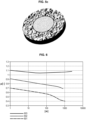
- figure 6 represents the evolution of the maximum normalized friction coefficient as a function of the kinematic length in m on a logarithmic scale, at a speed of 1.2 m/s, a pressure of 4 bars, and an ambient temperature of 25°C.
- test floor in friction is made at different stages of polishing, counted in kinematic length (1, 25, 250, 1000, 2500 m).
- the running-in is made at a single operating point (4 bars, 1.2 m/s, 25°C).
- test soil offers a very high level of normalized friction coefficient ( ⁇ ), even at very high cumulative sliding or kinematic lengths.
- the presence of the amorphous carbon coating does not significantly modify the reliefs, and improves the polishing resistance performance.
- Curves 601 and 602 represent the evolution observed on sandstone lapping soil. Curve 603 of the test soil is rigorously insensitive to polishing
Landscapes
- Chemical & Material Sciences (AREA)
- Engineering & Computer Science (AREA)
- Ceramic Engineering (AREA)
- Materials Engineering (AREA)
- Manufacturing & Machinery (AREA)
- Organic Chemistry (AREA)
- Structural Engineering (AREA)
- Inorganic Chemistry (AREA)
- Physics & Mathematics (AREA)
- Mechanical Engineering (AREA)
- General Physics & Mathematics (AREA)
- Optics & Photonics (AREA)
- Chemical Kinetics & Catalysis (AREA)
- Immunology (AREA)
- Health & Medical Sciences (AREA)
- Biochemistry (AREA)
- General Health & Medical Sciences (AREA)
- Pathology (AREA)
- Analytical Chemistry (AREA)
- Life Sciences & Earth Sciences (AREA)
- Plasma & Fusion (AREA)
- Automation & Control Theory (AREA)
- General Chemical & Material Sciences (AREA)
- Metallurgy (AREA)
- Road Paving Structures (AREA)
- Investigating Strength Of Materials By Application Of Mechanical Stress (AREA)
- Laser Beam Processing (AREA)
Description
- L'invention concerne un sol, en particulier un sol de test, et un procédé de fabrication associé. L'invention concerne également un dispositif, en particulier un dispositif de test, et un procédé associé.
- Des sols, en particulier des sols routiers, sont utilisés pour concevoir et tester de nouveaux matériaux et produits destinés à être utilisés sur des sols, par exemple en vue de fabriquer des éléments de pneus.
- Ainsi, au cours de la conception d'une partie d'un pneu, par exemple d'un matériau pour une bande de roulement d'un pneu, la caractérisation de son comportement sous sollicitation, par exemple sous couple moteur ou freineur ou sous dérive ou sous différentiel de glissement sol/pneu, est importante.
- Des tests sur des pistes externes, par exemple sur piste de freinage, sont relativement coûteux, longs et rendent difficilement compte de l'usure du pneu sur le long terme.
- Dans cette optique, des mesures peuvent viser à reproduire en laboratoire, sur un tribomètre, le frottement entre la partie de pneu, par exemple constituée de gomme, et le sol routier, responsable d'une grande partie de l'effort généré dans l'aire de contact du pneu avec le sol routier.
- Or les sols connus ne permettent pas en laboratoire d'effectuer des mesures représentatives d'un comportement sur un sol routier.
- En effet, on constate que les coefficients d'adhérence mesurés sur des dispositifs de test en laboratoire tels que des tribomètres sont sensiblement plus faibles que ceux sur des sols routiers, typiquement d'un facteur deux.
-
US 8 800 358 B2 divulgue un dispositif de test de pneu. - Un but de l'invention est de fournir un sol permettant de pallier ces inconvénients. Un but de l'invention est de fournir un sol pour des tests en laboratoire qui soit en mesure de représenter les caractéristiques d'un sol routier et qui soit suffisamment robuste pour un usage répété.
- A cet effet, il est prévu un sol selon la revendication 1.
- Il est ainsi possible d'obtenir un sol qui a les caractéristiques souhaitées, par exemple celles d'un sol routier, et qui peut être testé de manière répétée tout en conservant ses caractéristiques de frottement malgré un tel usage répété, ce qui permet d'assurer la pertinence des tests effectués.
- L'invention concerne également un dispositif de test d'un élément, comprenant :
- un tel sol, et
- des moyens d'application de l'élément sur le sol et de mise en mouvement relatif de l'élément et du sol.
- L'invention est avantageusement complétée par les caractéristiques suivantes, prises seules ou en une quelconque de leurs combinaisons techniquement possibles :
- le dispositif est une rouleuse,
- le dispositif est un tribomètre.
- L'invention concerne en outre un procédé de fabrication d'un tel sol selon la revendication 8.
- L'invention est avantageusement complétée par les caractéristiques suivantes, prises seules ou en une quelconque de leurs combinaisons techniquement possibles :
- une étape de génération d'un relief du substrat,
- une étape de génération d'un relief du substrat par fabrication additive, par exemple en céramique,
- une étape de génération du relief par usinage, par exemple par usinage laser,
- l'usinage laser est un usinage laser d'un massif comprenant du carbure de tungstène,
- l'usinage laser est un usinage laser d'un massif comprenant de l'acier inoxydable,
- une étape de génération du relief par fusion de surface par laser à partir d'une poudre d'acier inoxydable,
- l'étape d'obtention du substrat comprend en outre une étape de modulation du relief généré.
- L'invention concerne en outre un procédé de test d'un élément au moyen d'un tel dispositif, comprenant l'application de l'élément sur le sol et/ou la mise en mouvement relatif de l'élément par rapport au sol.
- D'autres caractéristiques et avantages de l'invention apparaitront lors de la description ci-après de modes de réalisation. Aux dessins annexés :
- les
figures 1a et 1b représentent des sols, lafigure 1a représentant un exemple qui ne fait pas partie de l'invention revendiquée. - la
figure 2 représente un procédé de fabrication selon un exemple de mode de réalisation de l'invention, - la
figure 3 représente un dispositif selon un exemple de mode de réalisation de l'invention, et - la
figure 4 représente un procédé de test selon un exemple de mode de réalisation de l'invention, - la
figure 5a représente un sol de référence selon un exemple de mode de réalisation de l'invention, - la
figure 5b représente un relief du sol de référence traité selon un exemple de mode de réalisation de l'invention, et - la
figure 5c représente le relief du sol de référence de lafigure 5b converti selon un exemple de mode de réalisation de l'invention, - la
figure 6 représente des mesures de coefficient de frottement en fonction de la longueur cinématique selon un exemple de mode de réalisation de l'invention. - En référence à la
figure 2 , il est décrit un procédé de fabrication d'un sol, par exemple d'un sol tel que décrit ci-après. - Le procédé comprend une étape 21 d'obtention d'un substrat 110, par exemple d'un substrat 110 tel que décrit ci-après. L'étape d'obtention du substrat 110 peut être une étape de génération du substrat 110 ou de fourniture du substrat 110.
- L'étape 21 peut comprendre une étape 212 de détermination d'un relief à reproduire. Le relief peut être défini comme une texture non plane, par exemple comme des variations d'altitude, par exemple par rapport à un plan médian. Le relief à reproduire peut être un macro-relief. Le macro-relief peut être défini vis-à-vis d'un micro-relief. Alternativement ou en complément, le macro-relief peut être défini comme le relief mesurable avec la précision d'une mesure de profondeur moyenne de texture, par exemple telle que décrite ci-après. Le macro-relief peut correspondre à un relief de taille caractéristique de l'ordre du centimètre, par exemple centimétrique.
- Il est ainsi possible de connaître le relief que l'on souhaite obtenir pour le sol.
- L'étape 212 peut comprendre une étape 2121 d'obtention de données relatives à un relief à reproduire, par exemple par des moyens de traitement de données, par exemple par une unité de traitement de données, par exemple par un processeur. Les données relatives à un relief à reproduire peuvent ainsi être stockées au préalable, par exemple par des moyens de stockage, par exemple par une unité de stockage, par exemple par une mémoire. Les données relatives à un relief à reproduire sont ainsi disponibles sans nécessité d'effectuer de mesure supplémentaire au préalable.
- Alternativement ou en complément, l'étape 212 peut comprendre une étape 2122 d'obtention d'un sol de référence. L'étape 2122 d'obtention d'un sol de référence peut être une étape de fabrication d'un sol de référence.
- En référence à la
figure 5a , il est décrit un sol de référence. Le sol de référence peut comprendre des granulats. Les granulats peuvent être des granulats de roches naturelles concassées et/ou de calibre d'environ 1 cm. Une telle structure de sol de référence présente une bonne résistance au polissage et une forte agressivité des petites échelles de par son relief, bien-au-delà des caractéristiques que pourrait présenter la roche naturelle. - Le sol de référence peut être un carottage de route. La route peut être un sol routier, par exemple un sol routier externe. Le sol routier peut comprendre du béton et/ou du bitume et/ou des roches naturelles concassées. L'étape 2122 peut ainsi comprendre un carottage de route. Le carottage de route peut comprendre un prélèvement du sol routier. Le sol de référence est par exemple un sol de type mosaïque, c'est-à-dire qu'il comprend une au moins une partie où les granulats sont disposés de manière adjacente les uns aux autres, un tel sol étant particulièrement adapté pour une utilisation avec un tribomètre.
- Le sol de référence peut ainsi fournir un modèle de relief que l'on souhaite reproduire pour le sol.
- Le sol de référence peut comprendre une couronne 510 texturée. La couronne 510 peut comprendre le relief à reproduire. La couronne 510 peut être disposée et/ou peut s'étendre entre un rayon de 21 mm et un rayon de 48 mm. De telles dimensions peuvent être adaptées aux tailles d'éprouvettes de tribomètre pour de telles applications. Le tribomètre peut être un tribomètre permettant une cinématique en rotation ou un tribomètre linéaire.
- L'étape 212 peut comprendre une étape 2123 de mesure d'un relief du sol de référence, par exemple du relief à reproduire. Il est ainsi possible d'obtenir une image de la surface du sol de référence. L'étape 2123 peut être réalisée par un profilomètre, par exemple un profilomètre optique, par exemple par projection de lumière structurée et/ou par mesure interférométrique et/ou par mesure confocale. Le profilomètre peut comprendre un capteur ayant une taille de champ de l'ordre de 10x10 cm, par exemple un capteur ayant une résolution de 100 µm. Le profilomètre est par exemple un profilomètre de modèle µsurf expert tel que commercialisé par nanofocus. Ainsi à l'issue de l'étape 2123, un relief du sol de référence mesuré peut être obtenu, par exemple sous la forme de données correspondant à la mesure du relief du sol de référence effectué.
- L'étape 212 peut comprendre une étape 2124 de traitement de données du relief du sol de référence mesuré à l'étape 2123. L'étape 2124 peut comprendre une recombinaison du relief du sol de référence mesuré à l'étape 2123. L'étape 2124 peut comprendre un filtrage du relief du sol de référence mesuré à l'étape 2123, par exemple un filtrage passe-bas, par exemple un filtrage passe-bas avec une longueur d'onde de coupure de 300 µm, par exemple un filtrage spatial à support glissant, par exemple un filtrage spatial à support glissant de taille de support 300 µm. L'étape 2124 peut comprendre un redressement du relief du sol de référence mesuré à l'étape 2123, par exemple une rotation d'un plan du relief, par exemple d'un plan moyen, le plan moyen pouvant être un plan moyen des sommets du relief, par exemple obtenu par régression linéaire. L'étape 2124 peut être mise en œuvre par les moyens de traitement de données. Ainsi à l'issue de l'étape 2124, un relief du sol de référence traité est obtenu, par exemple sous la forme de données correspondant à la mesure du relief du sol de référence effectué après le traitement de données. Le procédé peut comprendre l'affichage et/ou la représentation du relief du sol de référence traité, par exemple sur un terminal. Un exemple de relief du sol de référence traité correspondant à une surface, obtenu à l'étape 2124, est illustré par la
figure 5b . - Il est par exemple ainsi possible d'obtenir la profilométrie que l'on cherche à reproduire pour le sol.
- L'étape 212 peut comprendre une étape 2125 de conversion en solide du relief du sol de référence, par exemple mesuré à l'étape 2123 et/ou traité à l'étape 2124. L'étape 2125 peut comprendre la transformation du relief du sol de référence d'une représentation en deux dimensions à une représentation en trois dimensions, par exemple une transformation en un fichier en trois dimensions. L'étape 2125 peut être mise en œuvre par les moyens de traitement de données. Ainsi, à l'issue de l'étape 2125, un relief du sol de référence converti est obtenu, par exemple sous la forme de données correspondant à la mesure du relief du sol de référence effectuée, éventuellement après le traitement de données, et après la conversion. Le procédé peut comprendre l'affichage et/ou la représentation du relief du sol de référence converti, par exemple sur un terminal. Un exemple de relief du sol de référence converti de sorte à correspondre à un solide, obtenu à l'étape 2125, est illustré par la
figure 5c . - Des données ainsi obtenues peuvent former un ensemble d'instructions à fournir à un dispositif d'obtention et/ou de fabrication, par exemple une machine d'usinage, pour la réalisation du sol, en particulier du substrat et/ou relief.
- L'étape 212 peut comprendre une étape 2126 d'enregistrement du relief du sol de référence, par exemple mesuré à l'étape 2123 et/ou traité à l'étape 2124 et/ou converti en solide à l'étape 2125. L'enregistrement peut être réalisé sur les moyens de stockage, par exemple au moyen des moyens de traitement de données.
- L'étape 212 peut comprendre une étape 2127 de fabrication d'un prototype à partir de l'enregistrement réalisé à l'étape 2126 et/ou des données obtenues à l'étape 2121. La fabrication peut être réalisée par impression 3D. Le prototype peut être en résine. Il est ainsi possible de valider le relief obtenu via l'étape 212.
- L'étape 21 peut comprendre une étape 213 de génération d'un relief du substrat 110, par exemple d'un premier relief du substrat, par exemple du macro-relief. Le relief du substrat peut être généré selon le relief à reproduire, déterminé à l'étape 212, par exemple enregistré à l'étape 2126.
- Le relief peut être généré à l'étape 213 par enlèvement de matière, par exemple par une technique ablative.
- Le relief peut être généré par usinage.
- Le relief peut être généré par laser, par exemple par usinage laser. Le relief peut être réalisé par usinage laser, par exemple par usinage laser continu ou impulsionnel, par exemple par usinage laser nano-seconde, par exemple avec un diamètre de faisceau focalisé sur la surface compris entre 10 et 100 µm, par exemple entre 25 et 35 µm, par exemple de l'ordre de 30 µm. Le relief peut être réalisé par usinage laser d'une pièce, en particulier d'un massif.
- La pièce peut être une pièce métallique, en particulier un massif métallique, par exemple comprenant un acier, par exemple un acier inoxydable, par exemple un acier inoxydable X4CrNiMoN21-9-4. Le massif métallique peut être un massif en acier, par exemple en acier inoxydable, par exemple en acier inoxydable X4CrNiMoN21-9-4.
- La pièce peut comprendre un carbure, par exemple d'un carbure de tungstène. La pièce peut être un massif en carbure, par exemple en carbure de tungstène.
- La pièce peut avoir des dimensions générales de l'ordre de celles de la pièce finale, et/ou peut être lisse, et/ou peut avoir une épaisseur supérieure d'au moins un ordre de grandeur supérieur à la profondeur de texture visée, par exemple d'environ un ordre de grandeur.
- Un tel usinage permet ainsi de former le relief par ablation de matière. Cette technique est particulièrement avantageuse pour générer un sol représentatif d'un sol routier en asphalte neuf, en particulier vis-à-vis du coefficient d'adhérence gomme-sol mouillé.
- Le relief peut être généré par usinage par enlèvement de matière par un outil coupant, l'outil coupant ayant par exemple une arête coupante.
- Le relief peut être généré à l'étape 213 par fabrication additive.
- Le relief peut être généré par impression, par exemple par impression 3D. Le relief peut être généré en céramique. Une telle étape 213 peut comprendre une ou plusieurs étapes de dépôt de poudre de céramique et/ou de cuisson. Une telle technique peut permettre de générer le substrat dans son intégralité.
- Le relief peut être généré par fusion de surface par laser (« Surface Laser Melting » en terminologie anglo-saxonne), par exemple à partir d'une poudre, par exemple une poudre d'acier, par exemple d'acier inoxydable, par exemple d'acier inoxydable X4CrNiMoN21-9-4. Une telle technique peut permettre de générer le substrat dans son intégralité.
- Le relief ainsi généré peut être le relief définitif du substrat 110 du sol. Alternativement, le procédé peut comprendre une modification du relief généré à l'étape 213.
- Le procédé, par exemple l'étape 21, peut ainsi comprendre une étape 214 de modulation du relief généré, par exemple de modulation de rugosités, par exemple de modulation d'amplitude, par exemple de micro-reliefs ou de micro-rugosités, du relief généré à l'étape 213, par exemple de sorte à obtenir un deuxième relief du substrat. Le procédé, par exemple l'étape 21, peut ainsi comprendre une étape 214 d'atténuation du relief généré, par exemple d'atténuation de rugosités, par exemple de réduction d'amplitude, par exemple de micro-reliefs ou de micro-rugosités, du relief généré à l'étape 213. Alternativement ou en complément, le procédé, par exemple l'étape 21, peut ainsi comprendre une étape 214 d'amplification du relief généré, par exemple d'amplification de rugosités, par exemple d'augmentation d'amplitude, par exemple de micro-reliefs ou de micro-rugosités, du relief généré à l'étape 213.
- Dans ce cas, le relief généré à l'étape 213 est un premier relief modifié à l'étape 214 dans le cadre de la fabrication du sol. Les rugosités modulées sont par exemple des micro-reliefs et/ou des micro-rugosités. Le micro-relief peut être défini par exemple vis-à-vis du macro-relief, le macro-relief étant de plus grande amplitude que le micro-relief. Alternativement ou en complément, le micro-relief peut être défini comme un relief de taille inférieure à 100 µm. Alternativement ou en complément, le micro-relief peut être défini comme le relief de taille inférieure à la précision permise par la technique de génération de relief mise en œuvre à l'étape 213, par exemple par usinage ou ablation, en particulier usinage ou ablation laser, par exemple mesurable avec la précision d'une mesure de profondeur moyenne de texture, par exemple telle que décrite ci-après, mais non maîtrisable par la technique de génération de relief mise en œuvre à l'étape 213. Par micro-rugosités, on entend par exemple un relief dont la longueur d'onde est inférieure à la plus petite rugosité décrite par le relief enregistré à l'étape 2127 et/ou les données de relief obtenues à l'étape 2121, et/ou inférieure à la précision permise par la technique de génération de relief mise en œuvre à l'étape 213, par exemple par usinage ou ablation, en particulier usinage ou ablation laser. Il est ainsi possible de s'approcher des micro-reliefs mesurés sur les sols à reproduire en laboratoire, par exemple les sols routiers.
- La modulation peut être réalisée par laser. L'étape 214 peut ainsi comprendre une première étape 2141 de modulation par fusion de surface par laser. Il est ainsi possible de faire refondre la surface du relief, par exemple pour en moduler des rugosités locales. L'étape 214 peut comprendre une deuxième étape 2142 de modulation par laser impulsionnel femto-seconde, par exemple ultérieurement ou alternativement à la première étape 2141. L'étape 214, de préférence les étapes 2141 et/ou 2142, est de préférence réalisée après une étape 212 dans laquelle le relief est généré par fabrication additive, en particulier par impression 3D.
- Ainsi, à l'issue de l'étape 21, le relief du substrat 110 est obtenu. Le relief du substrat peut définir le ou correspondre au relief d'une surface d'utilisation 120 telle que décrite ci-après. La partie du substrat 110 où est situé le relief peut former au moins partiellement ou intégralement la surface d'utilisation 120. Alternativement un traitement telle que décrit ci-après, par exemple tel qu'une formation d'un revêtement de surface peut être appliqué sur le relief, par exemple de sorte à former au moins partiellement ou intégralement la surface d'utilisation 120. Dans ce cas, la surface d'utilisation est au moins partiellement disposée au-dessus du relief du substrat 110.
- Le procédé comprend une étape 22 de traitement de surface. L'étape 22 comprend une étape 222 d'obtention, par exemple de formation, par exemple de dépôt, d'un revêtement de surface 122, comprenant du nitrure de titane et/ou du nitrure de chrome. Le revêtement de surface peut aussi comprendre du carbone amorphe et/ou carbure de tungstène. Le revêtement de surface peut être un revêtement de surface tel que décrit ci-après.
- Il est ainsi possible d'augmenter la dureté en surface, en particulier la dureté au niveau d'une surface d'utilisation, par exemple telle que décrite ci-après. Il est ainsi possible d'offrir une grande résistance au polissage.
- L'étape 22 est de préférence mise en œuvre lorsque l'étape 213 de génération du relief a été réalisée par fusion de surface par laser et/ou par usinage laser nano-seconde d'un massif en acier inoxydable.
- Le procédé peut être réalisé de sorte que le matériau choisi pour le substrat garantisse un haut niveau de dureté sans revêtement de surface, de préférence lorsque des moyens 312 d'application tels que décrits ci-après comprennent un moteur adapté pour mettre en mouvement relatif l'élément 32.
- Le procédé peut comprendre une étape 23 de validation du sol obtenu à l'étape 21 et/ou 22. La validation peut être réalisée en conditions de frottement sec et/ou mouillé. La validation peut comprendre une mesure avec un tribomètre, en particulier un tribomètre linaire, et/ou avec une rouleuse. La validation peut comprendre la comparaison de la mesure avec une courbe de frottement.
- En référence aux
figures 1a et 1b , il est décrit un sol. Le sol est par exemple un sol de test, par exemple de test d'un élément, par exemple un sol de test de pneu et/ou de partie de pneu et/ou de gomme. - Le sol comprend un substrat 110. Le substrat 110 a un module d'Young compris entre 100 et 1000 GPa, de préférence entre 100 et 500 GPa. Un tel module d'Young dépasse largement celui d'une gomme, qui est au maximum de 3 à 10 GPa, par exemple en compression dans le domaine vitreux. Un tel module d'Young dépasse également celui de l'aluminium. Ainsi, même en cours d'utilisation, la gomme reste largement plus déformable que le substrat qui en comparaison ne se déforme pas.
- Le sol comprend une surface d'utilisation 120. La surface d'utilisation est un revêtement de surface tel que décrit ci-après. Le sol présente au niveau de la surface d'utilisation 120 une dureté Vickers comprise entre 1300 et 10000 kgf/mm2, de préférence entre 1500 et 3500 kgf/mm2. La surface d'utilisation permet ainsi au sol d'atteindre des duretés importantes.
- « kgf » signifie kilogramme-force, et 1 kgf = 9,806 65 N.
- Il est ainsi possible d'obtenir un sol qui a les caractéristiques souhaitées, par exemple celles d'un sol routier, et qui peut être testé de manière répétée tout en conservant ses caractéristiques de frottement malgré un tel usage répété, ce qui permet d'assurer la pertinence des tests effectués. Un tel sol est particulièrement efficace pour tester des caractéristiques d'adhérence, par exemple sur sol sec et/ou sol mouillé.
- Le sol est par exemple obtenu par le procédé de fabrication décrit ci-avant.
- En outre, un tel sol peut également être efficace pour tester des caractéristiques d'efforts pneu/sol, par exemple au moyen d'un dispositif de test tel que décrit ci-après, pour laquelle les sols connus sont soit incapables d'avoir une topographie représentative d'un sol routier, soit présentent une usure trop importante nécessitant des changements de sol trop fréquents. Contrairement aux sols connus, il est ainsi possible d'éviter à la fois des problèmes de coûts et de reproductibilité.
- En effet, les sols de l'art antérieurs utilisés en laboratoires ne reproduisent pas les caractéristiques d'un sol routier et/ou s'usent de manière prématurée, ce qui nuit fortement à la reproductibilité des tests utilisant les sols de l'art antérieur.
- Un des mécanismes de l'adhérence du pneu sur sol mouillé provient de la déformation de la gomme qui glisse sur le sol. De par la viscoélasticité du matériau du pneu, cette déformation entraîne une dissipation d'énergie qui se traduit directement en termes d'efforts de frottement. La connaissance et la maîtrise de la rugosité du sol est donc critique pour assurer la pertinence de la mesure de frottement en laboratoire par rapport aux mesures d'adhérence sur pneu complet sur piste de freinage.
- Les sols routiers sont généralement constitués de liant bitumineux et de granulats de roches concassées dont la nature pétrographique et la taille sont variables d'un sol à l'autre. En termes de rugosités, les sols routiers se distinguent par leur caractère multi-échelle (taille caractéristique de rugosité allant de 1 cm à 1 µm voire moins) et leur structure quasi fractale.
- Une des difficultés surmontées par le sol décrit ici permettant d'améliorer la pertinence de la mesure laboratoire est de garantir que la rugosité du sol sur laquelle la gomme frotte lors d'un test puisse bien représenter les caractéristiques d'un sol routier. A ce sujet, il est ici possible de définir le terme de longueur cinématique comme étant la longueur cumulée de gomme qui glisse sur un point du sol. Sur un contact réel entre la gomme d'un pneu et un sol routier d'une piste de freinage utilisée intensivement, la longueur cinématique vue par un point du sol pendant une utilisation de deux ans de la piste de freinage est de l'ordre d'une dizaine de mètres. A contrario, au laboratoire, la caractérisation de nombreux points de fonctionnement de la gomme (pression, vitesse, température) combinée au fait que le frottement se fait toujours au même endroit conduit à des longueurs cinématiques vues par un point du sol bien supérieures, de plusieurs ordres de grandeur (environ 10 km par granulat en un an d'utilisation labo). Il en résulte une manifestation des phénomènes de polissage/érosion de la roche nettement plus rapide au laboratoire que sur les pistes externes. Ceci se manifeste par des niveaux d'adhérence au laboratoire systématiquement plus faibles que sur les pistes externes et qui évoluent fortement au cours de la vie du sol.
- L'état de l'art actuel montre qu'aucune roche naturelle ne permet de limiter le mécanisme de polissage et de maintenir des niveaux d'adhérence comparables à ceux des pistes externes.
- Le sol décrit ici, et qui peut être obtenu au moyen du procédé décrit ci-avant, de par le module élastique du substrat et la dureté de sa surface d'utilisation et/ou le matériau du revêtement de surface, permet de pallier ces inconvénients
- Le substrat 110 peut comprendre ou être formé d'un massif, par exemple d'un massif métallique. Le substrat 110 peut comprendre de l'acier, par exemple de l'acier inoxydable, par exemple de l'acier inoxydable X4CrNiMoN21-9-4 et/ou de l'acier inoxydable austénitique, par exemple de l'acier inoxydable X2CrNi18-9, et/ou du carbure, par exemple du carbure de tungstène, et/ou de la céramique, par exemple de la céramique zircone, par exemple de la zircone Zr700. Le substrat 110 peut comprendre ou être formé et/ou constitué d'un massif en acier, par exemple en acier inoxydable, par exemple en acier inoxydable X4CrNiMoN21-9-4 et/ou et/ou en acier inoxydable austénitique, par exemple en acier inoxydable X2CrNi18-9 en carbure de tungstène et/ou en céramique, par exemple en céramique zircone, par exemple en zircone Zr700.
- Le sol peut présenter au niveau de la surface d'utilisation 120 une dureté Vickers comprise entre 1300 et 10000 kgf/mm2, de préférence entre 1500 et 3500 kgf/mm2.
- Le sol comprend un revêtement de surface 130. Il est ainsi possible d'augmenter la dureté en surface, en particulier la dureté au niveau de la surface d'utilisation. Il est ainsi possible d'offrir une grande résistance au polissage.
- Le revêtement de surface 130 peut avoir une épaisseur comprise entre 0,1 et 100 µm, de préférence entre 2 et 5 µm, de préférence 3 µm. L'épaisseur du revêtement peut ainsi être choisie pour ne pas modifier l'amplitude des rugosités, et donc ne pas modifier la réponse en frottement du substrat.
- Le revêtement de surface 130 peut comprendre du carbone amorphe (« Diamond-Like Carbon » en terminologie anglo-saxonne) et, selon l'invention, comprend du nitrure de titane, et/ou du nitrure de chrome. Le revêtement peut ainsi comprendre du carbure de tungstène.
- Le revêtement de surface 130 comprend la surface d'utilisation 120.
- La surface d'utilisation 120 peut former une surface de test. La surface d'utilisation 120 peut être adaptée de sorte à ce que l'élément à tester soit appliqué dessus.
- La surface d'utilisation 120 peut avoir un relief tel que décrit ci-avant.
- La profondeur moyenne de texture au niveau de la surface d'utilisation 120 est comprise entre 0,3 et 1,7 mm, par exemple d'1 mm. La profondeur moyenne de texture est établie en accord avec le Règlement (UE) N° 228/2011 de la Commission Européenne du 7 mars 2011, Annexe V 3.1(4).
- Le coefficient d'adhérence entre une gomme et le sol au niveau de la surface d'utilisation 120 peut être compris entre 0,5 et 2. Un tel coefficient d'adhérence est par exemple mesuré par un test de frottement linéaire stationnaire en conditions mouillées, par exemple dans des conditions ou la surface d'utilisation 120 et/ou le sol est baigné dans de l'eau, pour une longueur glissée, ou une longueur cinématique, cumulée de 100 mm, à 4 bars, pour une vitesse de 1 m/s, à température d'eau de 25°C. La longueur glissée, ou longueur cinématique, cumulée est la quantité de déplacement relatif de deux surfaces, par exemple celles de la gomme et du sol, cumulée dans le repère du sol.
- La gomme pour l'établissement du coefficient d'adhérence peut être une gomme ayant une composition représentative des gommes utilisées en mélange bande de roulement pneu.
- La gomme pour l'établissement du coefficient d'adhérence peut être caractérisée par un facteur de perte tan(δ) et un module complexe G*.
- La propriété dynamique max(tan(δ)) est par exemple mesurée sur un viscoanalyseur 5 (Metravib V A4000), selon la norme ASTM D 5992 - 96. La mesure comprend l'enregistrement d'une réponse d'un échantillon de composition vulcanisée (par exemple une éprouvette cylindrique de 4 mm d'épaisseur et de 400 mm2 de section), soumis à une sollicitation sinusoïdale en cisaillement simple alterné, à la fréquence de 10 Hz, dans des conditions normales de température (par exemple 23°C) selon la norme ASTM D 1349 - 99. La réponse enregistrée est ensuite soumise à un balayage en amplitude de déformation crête à crête de 0,1 à 50% (cycle aller), puis de 50% à 1 % (cycle retour). Le résultat exploité est le facteur de perte tan(δ). Pour le cycle retour, on indique la valeur maximale de tan(δ) observée max(tan(δ)).
- Le module complexe est par exemple mesuré de la manière suivante. La mesure comprend l'enregistrement d'une réponse d'un échantillon de composition vulcanisée soumis à une sollicitation sinusoïdale en cisaillement simple alterné lors d'un balayage en température, soumis à une sollicitation sinusoïdale à contrainte imposée de 0,7 MPa et à une fréquence de 10 Hz, la température allant de -60°C à 100°C, à raison une vitesse de 1,5°C par minute. La température du maximum de tan(δ) de la gomme de la réponse enregistrée, notée « Tg (°C) max(tan(δ)) ». Un autre résultat exploité est le module complexe de cisaillement dynamique (G*), par exemple à 60°C. Pour plus de lisibilité les résultats de G* seront indiqués en base 100, la valeur 100 étant attribuée au témoin. Un résultat inférieur à 100 indiquant une diminution de la valeur concernée, et inversement, un résultat supérieur à 100, indiquera une augmentation de la valeur concernée.
- La surface d'utilisation, par exemple le sol, peut avoir une forme comprenant au moins une portion courbe, par exemple un arc de cercle. La surface d'utilisation, par exemple le sol, peut avoir une forme comprenant au moins une courbe fermée, par exemple un cercle. Le sol, peut ainsi former un volant.
- La surface d'utilisation, par exemple le sol, peut avoir une forme comprenant au moins une portion formant une bande, par exemple une forme de bande fermée sur elle-même, par exemple une forme de chenille. Une telle surface d'utilisation ou un tel sol peut être utilisé au moyen d'une rouleuse de type « flat track » comme décrit ci-après.
- Le sol peut former une éprouvette. Le sol peut avoir des dimensions adaptées pour former une éprouvette adaptée pour être utilisée par un dispositif de test tel que décrit ci-après.
- En référence à la
figure 3 , il est décrit un dispositif 31 de test d'un élément 32. Le dispositif 31 comprend un sol 1 tel que décrit ci-avant. Le dispositif 31 comprend des moyens 312 d'application de l'élément 32 sur le sol 1, par exemple de l'élément 32 sur la surface d'utilisation 120, et/ou de mise en mouvement relatif de l'élément 32 et du sol 1. - Les moyens 312 d'application peuvent comprendre un applicateur adapté pour appliquer l'élément 32 sur le sol 1. L'applicateur peut comprendre un bras.
- Le mouvement peut être un mouvement rectiligne ou de rotation. Le mouvement peut être un mouvement du sol, l'élément 32 restant fixe.
- Les moyens 312 d'application peuvent comprendre un moteur et/ou un arbre et/ou un bras adapté(s) pour mettre en mouvement relatif l'élément 32 et le sol.
- L'élément 32 peut être ou comprendre un pneu et/ou une partie de pneu et/ou une gomme. L'élément 32 peut être ou comprendre au moins une portion de roue, par exemple une roue.
- Les moyens 312 d'application peuvent être adaptés pour réguler une vitesse de l'élément 31 par rapport au sol, par exemple une vitesse de déplacement linéaire ou une vitesse de déplacement annulaire, par exemple une vitesse de rotation. La vitesse peut être comprise entre 0,5 et 1,5 m/s, par exemple entre 0,9 et 1,2 m/s.
- Le dispositif peut comprendre des moyens de contrôle de température peuvent contrôler la température ambiante et/ou la température initiale de l'élément 31. Le dispositif et/ou un ensemble ou un système comprenant le dispositif peut comprendre les moyens de contrôle de température. Les moyens de contrôle de température peuvent comprendre un dispositif de contrôle de température, par exemple un thermostat, par exemple un chauffage, par exemple une résistance, et/ou un dispositif de refroidissement. Le dispositif est par exemple configuré pour contrôler la température de sorte à la maintenir entre 20 et 30°C, par exemple à 25°C.
- Le dispositif peut comprendre des moyens de mesure d'au moins une grandeur physique, par exemple une ou plusieurs grandeurs physiques. Les moyens de mesure peuvent comprendre un capteur de mesure d'au moins une grandeur physique, par exemple un effort et/ou un moment.
- Le dispositif peut comprendre des moyens de traitement de données, par exemple par une unité de traitement de données, par exemple par un processeur. Les moyens de traitement de données sont par exemple les mêmes que ceux déjà décrits dans le cadre du procédé de fabrication et/ou les mêmes que ceux décrits dans le cadre du procédé d'utilisation ci-après.
- Le dispositif 31 peut être un tribomètre, par exemple un tribomètre linéaire ou un tribomètre ayant une configuration de rotation ou tribomètre rotatif.
- Les moyens 312 d'application peuvent être adaptés pour appliquer un effort normal au sol, par exemple normal à un plan médian, par exemple normal à un plan médian correspondant à la surface d'utilisation, par exemple de sorte à contrôler une pression moyenne de contact de l'élément 32 sur le sol.
- Les moyens 312 d'application sont par exemple adaptés pour déplacer l'élément 31 de manière tangentielle par rapport au sol, par exemple à la surface d'utilisation. Lorsque le tribomètre est linaire, le déplacement peut être une translation rectiligne. Alternativement, lorsque le tribomètre est rotatif, le déplacement peut suivre une trajectoire annulaire, par exemple être une rotation.
- Les moyens de mesure peuvent être adaptés pour mesurer un effort, en particulier un effort tangentiel. La ou les grandeur(s) physique(s), par exemple l'effort, peu(ven)t être mesurée(s) au niveau de l'interface entre l'élément 32 et le sol.
- Le dispositif, par exemple les moyens de traitement de données, peut être adapté pour déterminer en sortie un coefficient de frottement adimensionné en normant l'effort tangentiel par l'effort normal.
- Le dispositif 31 peut être une rouleuse. La rouleuse peut être un dispositif adapté pour faire rouler l'élément 32. La rouleuse peut être adaptée pour piloter l'orientation de l'élément 32, par exemple l'orientation du plan médian de l'élément 32, par exemple l'orientation du plan médian de la roue ou de la partie de roue de l'élément 32 ou formant l'élément 32, de sorte à appliquer à l'élément 32 des sollicitations. Alternativement ou en complément, la rouleuse peut être adaptée pour piloter la vitesse de l'élément 32 de sorte à appliquer à l'élément 32 des sollicitations, Alternativement ou en complément, la rouleuse peut être adaptée pour piloter le couple appliqué à l'élément 32, par exemple au centre de l'élément 32, par exemple au centre de la roue ou de la partie de roue de l'élément 32.
- Les moyens 312 peuvent être adaptés pour appliquer un effort de l'élément 32 sur le sol, par exemple un effort d'intensité croissante dans le temps, par exemple jusqu'à atteindre une consigne de force.
- Les moyens de mesure peuvent être adaptés pour mesurer un effort et/ou un moment. L'au moins une grandeur physique, par exemple l'effort, peut être mesurée au centre de l'élément, par exemple au centre de la roue de l'élément 32.
- Le dispositif, par exemple les moyens de traitement de données, peut être adapté pour déterminer l'adhérence de l'élément par rapport au sol, par exemple à partir de l'effort et/ou du moment mesuré(s) par les moyens de mesure.
- La rouleuse peut être une rouleuse de type « flat-track » (« piste plane » en terminologie anglo-saxonne). Pour une telle rouleuse, la surface d'utilisation, par exemple le sol, peut avoir une forme comprenant au moins une portion formant une bande comme décrit ci-avant.
- En référence à la
figure 4 , il est décrit un procédé de test de l'élément. L'élément peut être testé au moyen du dispositif 31. - Le procédé peut comprendre une étape 41 d'application de l'élément 32 sur le sol 1.
- Le procédé peut comprendre une étape 42 de mesure du comportement de l'élément 32 sur le sol 1, en particulier sur la surface d'utilisation 110.
- Le dispositif est ou comprend par exemple la rouleuse telle que décrite ci-avant.
- L'étape 41 peut être mise en œuvre sans rotation relative et/ou absolue de l'élément et/ou du sol. L'étape 41 peut alors comprendre l'application d'un effort de l'élément 32 sur le sol, par exemple un effort croissant en intensité dans le temps, par exemple jusqu'à atteindre une consigne de force.
- Alternativement, ou en complément dans une autre étape 41 d'application de l'élément sur le sol, l'étape 41 peut comprendre la mise en rotation du sol par rapport à l'élément, par exemple de sorte que le sol entraîne l'élément en rotation de sorte que sol et élément sont chacun en rotation dans le référentiel du laboratoire. La rotation de l'élément 32 peut être régulée, en couple et/ou en taux de glissement, par exemple en fonction d'une consigne d'asservissement. La consigne d'asservissement peut comprendre une consigne de couple nul ou non nul à une valeur prédéterminée. La consigne d'asservissement peut comprendre une consigne de taux de glissement nul ou non nul à une valeur prédéterminée.
- Alternativement, ou en complément dans une autre étape 41 d'application de l'élément sur le sol, une animation peut être appliquée à l'élément 32, par exemple une variation d'angle de dérive de l'élément par rapport au sol et/ou une variation d'angle de carrossage de l'élément par rapport au sol et/ou une variation de charge, et/ou une variation de taux de glissement.
- L'étape 42 peut comprendre la mesure d'un ou plusieurs effort(s) et/ou d'un ou plusieurs moment(s), par exemple au centre de la roue lorsque l'élément 32 comprend une roue comme décrit ci-avant.
- Le procédé peut comprendre l'obtention de l'adhérence de l'élément par rapport au sol, par exemple par les moyens de traitement, par exemple à partir des mesures d'effort(s) et de moment(s).
- Le dispositif est ou comprend par exemple le tribomètre tel que décrit ci-avant.
- L'étape 41 peut comprendre l'application d'un effort normal au sol, par exemple normal à un plan médian, par exemple normal à un plan médian correspondant à la surface d'utilisation, par exemple de sorte à contrôler une pression moyenne de contact de l'élément 32 sur le sol.
- L'étape 41 peut comprendre l'application de l'élément 31 de manière tangentielle par rapport au sol, par exemple à la surface d'utilisation. Lorsque le tribomètre est linaire, le déplacement peut être une translation rectiligne. Alternativement, le déplacement peut suivre une trajectoire annulaire, par exemple être une rotation.
- L'étape 41 peut comprendre le contrôle de la température ambiante et/ou la température initiale de l'élément 31. Le dispositif et/ou un ensemble ou un système comprenant le dispositif peut comprendre les moyens de contrôle de température.
- L'étape 42 peut comprendre la mesure d'un effort, en particulier un effort tangentiel. L'au moins une grandeur physique, par exemple l'effort, peut être mesurée au niveau de l'interface entre l'élément 32 et le sol.
- Le procédé peut comprendre la détermination en sortie d'un coefficient de frottement adimensionné en normant l'effort tangentiel par l'effort normal, par exemple par les moyens de traitement.
- En référence à la
figure 6 , il est décrit un exemple détaillé mettant en œuvre un sol de test qui ne fait pas partie de l'invention revendiquée. - Le substrat du sol est métallique, en acier inoxydable X4CrNiMoN21-9-4, dont le relief a été généré par usinage laser impulsionnel à partir d'un massif, par exemple par usinage laser impulsionnel nano-seconde.
- Le revêtement de surface du sol est constitué de carbone amorphe d'environ 3 µm.
- Le relief reproduit correspond à un sol de référence.
- Pour le sol de test, seule la couronne du sol de référence comprise entre un rayon de 30 mm et un rayon 46 mm est texturée de sorte à présenter le relief.
- La surface du sol de référence a été préalablement convertie en solide et enregistrée pour permettre la fabrication du sol de test.
- L'évolution du sol de test avec les frottements est testée par un tribomètre. La
figure 6 représente l'évolution du coefficient de frottement normalisé maximum en fonction de la longueur cinématique en m en échelle logarithmique, à une vitesse de 1,2 m/s, une pression de 4 bars, et une température ambiante de 25°C. - L'observation du sol de test en frottement est faite à différents stades de polissage, comptabilisés en longueur cinématique (1, 25, 250, 1000, 2500 m). Le rodage est fait à un point de fonctionnement (4 bars, 1,2 m/s, 25°C) unique.
- Le sol de test offre un niveau de coefficient de frottement normalisé (µ) très élevé, même à des longueurs glissées ou cinématiques cumulées très élevées.
- Par ailleurs, pendant la mesure le sol de test évolue peu visuellement.
- La présence du revêtement en carbone amorphe ne modifie pas notablement les reliefs, et améliore la performance résistance au polissage.
- Les courbes 601 et 602 représentent l'évolution constatée sur sol de rodage en grès. La courbe 603 du sol de test est rigoureusement insensible au polissage
Claims (14)
- Sol comprenant un substrat (110) ayant un module d'Young compris entre 100 et 1000 GPa, comprenant un revêtement de surface formant une surface d'utilisation, dans lequel le revêtement de surface comprend du nitrure de titane, et/ou du nitrure de chrome, la surface d'utilisation présentant un relief avec une profondeur moyenne de texture comprise entre 0,3 et 1,7 mm.
- Sol selon la revendication 1 présentant au niveau d'une surface d'utilisation (120) une dureté Vickers comprise entre 1300 et 10000 kgf/mm2, le revêtement de surface comprenant en outre du carbone amorphe et/ou du carbure de tungstène.
- Sol selon l'une quelconque des revendications 1 à 2, dans lequel le revêtement de surface a une épaisseur comprise entre 2 et 5 µm.
- Sol selon l'une quelconque des revendications 1 à 3, dans lequel le substrat a un module d'Young compris entre 100 et 500 GPa, et/ou dans lequel le sol présente au niveau de la surface d'utilisation une dureté Vickers comprise entre 1500 et 3500 kgf/mm2, et/ou dans lequel le substrat comprend de l'acier inoxydable, et/ou du carbure de tungstène, et/ou de la céramique.
- Sol selon l'une quelconque des revendications précédentes, dans lequel le coefficient d'adhérence entre une gomme et le sol au niveau de la surface d'utilisation du sol est compris entre 0,5 et 2, la gomme étant une gomme ayant une composition représentative des gommes utilisées en mélange bande de roulement pneu.
- Dispositif de test d'un élément, comprenant :- un sol selon l'une quelconque des revendications précédentes, et des moyens (312) d'application de l'élément sur le sol et/ou de mise en mouvement relatif de l'élément et du sol.
- Dispositif de test selon la revendication 6, dans lequel le dispositif est une rouleuse, ou dans lequel le dispositif est un tribomètre et dans lequel l'élément comprend une gomme, le dispositif étant configuré pour que le coefficient d'adhérence entre la gomme et le sol au niveau de la surface d'utilisation du sol est compris entre 0,5 et 2.
- Procédé de fabrication d'un sol selon l'une quelconque des revendications 1 à 5, le procédé comprenant une étape (21) d'obtention du substrat et une étape de traitement de surface comprenant une étape de formation du revêtement de surface formant la surface d'utilisation.
- Procédé selon la revendication 8, dans lequel l'étape d'obtention du substrat comprend une étape (212) de détermination d'un relief à reproduire, l'étape (212) de détermination d'un relief à reproduire comprenant une étape (2122) d'obtention d'un sol de référence, par exemple par carottage de route, et une étape (2123) de mesure d'un relief du sol de référence.
- Procédé selon l'une quelconque des revendications 8 à 9, dans lequel l'étape d'obtention du substrat comprend une étape (213) de génération d'un relief du substrat par fabrication additive en céramique, ou dans lequel l'étape d'obtention du substrat comprend une étape (213) de génération d'un relief par usinage, par exemple par usinage laser.
- Procédé selon la revendication 10, dans lequel l'usinage laser est un usinage laser d'un massif comprenant du carbure de tungstène, ou dans lequel l'usinage laser est un usinage laser d'un massif comprenant de l'acier inoxydable.
- Procédé selon l'une quelconque des revendications 10 à 11, dans lequel l'étape d'obtention du substrat comprend une étape (213) de génération du relief par fusion de surface par laser à partir d'une poudre d'acier inoxydable.
- Procédé selon l'une quelconque des revendications 8 à 12, dans lequel l'étape d'obtention du substrat comprend en outre une étape (214) de modulation du relief généré.
- Procédé de test d'un élément au moyen du dispositif de l'une quelconque des revendications 6 à 7, comprenant l'application de l'élément sur le sol et/ou la mise en mouvement relatif de l'élément par rapport au sol.
Applications Claiming Priority (2)
| Application Number | Priority Date | Filing Date | Title |
|---|---|---|---|
| FR1762352A FR3075231B1 (fr) | 2017-12-18 | 2017-12-18 | Sol et dispositif et procedes associes |
| PCT/FR2018/053357 WO2019122673A1 (fr) | 2017-12-18 | 2018-12-18 | Sol et dispositif et procédés associes |
Publications (2)
| Publication Number | Publication Date |
|---|---|
| EP3728691A1 EP3728691A1 (fr) | 2020-10-28 |
| EP3728691B1 true EP3728691B1 (fr) | 2025-02-19 |
Family
ID=61599380
Family Applications (1)
| Application Number | Title | Priority Date | Filing Date |
|---|---|---|---|
| EP18833960.0A Active EP3728691B1 (fr) | 2017-12-18 | 2018-12-18 | Sol et dispositif et procédés associes |
Country Status (5)
| Country | Link |
|---|---|
| US (1) | US11618082B2 (fr) |
| EP (1) | EP3728691B1 (fr) |
| CN (1) | CN111566254B (fr) |
| FR (1) | FR3075231B1 (fr) |
| WO (1) | WO2019122673A1 (fr) |
Families Citing this family (3)
| Publication number | Priority date | Publication date | Assignee | Title |
|---|---|---|---|---|
| US20230319218A1 (en) | 2022-04-01 | 2023-10-05 | Nvidia Corporation | Image stitching with dynamic seam placement based on ego-vehicle state for surround view visualization |
| US20240370971A1 (en) * | 2023-05-05 | 2024-11-07 | Nvidia Corporation | Image stitching with ego-motion compensated camera calibration for surround view visualization |
| US12524960B2 (en) | 2023-07-14 | 2026-01-13 | Nvidia Corporation | Spatial masking for stitched images and surround view visualizations |
Citations (3)
| Publication number | Priority date | Publication date | Assignee | Title |
|---|---|---|---|---|
| US20060134424A1 (en) * | 2003-06-16 | 2006-06-22 | Commissariat A L'energie Atomque | Coating for a mechanical part comprising at least one hydrogenated amorphous carbon, and method of depositing one such coating |
| US20060169034A1 (en) * | 2005-01-31 | 2006-08-03 | Cooper Tire & Rubber Company | Method and apparatus for testing rubber tires or solid rubber wheel laboratory samples |
| US8800358B2 (en) * | 2011-08-03 | 2014-08-12 | Kobe Steel, Ltd. | Road surface member for tire testing machine and manufacturing method of the same |
Family Cites Families (14)
| Publication number | Priority date | Publication date | Assignee | Title |
|---|---|---|---|---|
| JPH04350536A (ja) * | 1991-05-28 | 1992-12-04 | Yokohama Rubber Co Ltd:The | タイヤ試験機 |
| JP4127887B2 (ja) * | 1998-01-23 | 2008-07-30 | 株式会社ブリヂストン | 自動二輪車用空気入りタイヤ |
| JP3739029B2 (ja) * | 1999-12-16 | 2006-01-25 | 住友ゴム工業株式会社 | 摩擦試験装置 |
| EP1914268B1 (fr) * | 2001-03-21 | 2010-04-28 | Bridgestone Corporation | Ensemble pneu-jante |
| EP1293917B1 (fr) * | 2001-09-18 | 2005-07-27 | Sumitomo Rubber Industries Ltd. | Méthode de simulation d'un bandage pneumatique roulant |
| JP4506530B2 (ja) * | 2005-03-24 | 2010-07-21 | 東海ゴム工業株式会社 | 多孔質弾性舗装材 |
| FR2896807B1 (fr) * | 2006-01-30 | 2008-03-14 | Eads Ccr Groupement D Interet | Structure multicouche mince, piece la comprenant et son procede de depot |
| KR100784279B1 (ko) * | 2006-11-20 | 2007-12-12 | 한국타이어 주식회사 | 주행중 타이어의 강성 측정방법 |
| JP5466724B2 (ja) * | 2012-03-14 | 2014-04-09 | 住友ゴム工業株式会社 | タイヤの台上試験装置及びこれを用いたタイヤ性能試験方法 |
| GB201311849D0 (en) * | 2013-07-02 | 2013-08-14 | Element Six Ltd | Super-hard constructions and methods for making and processing same |
| JP6291366B2 (ja) * | 2014-06-25 | 2018-03-14 | 住友ゴム工業株式会社 | タイヤのシミュレーション方法及びシミュレーション装置 |
| JP6495033B2 (ja) * | 2015-02-09 | 2019-04-03 | 株式会社神戸製鋼所 | タイヤ試験用リム |
| CN104634589B (zh) * | 2015-02-11 | 2017-09-29 | 中信戴卡股份有限公司 | 一种用于模拟路面的转鼓 |
| KR20170046961A (ko) * | 2015-10-22 | 2017-05-04 | 장철환 | 타이어 마모 시험용 마찰시그먼트를 구비한 타이어 마모 시험용 회전드럼 |
-
2017
- 2017-12-18 FR FR1762352A patent/FR3075231B1/fr active Active
-
2018
- 2018-12-18 WO PCT/FR2018/053357 patent/WO2019122673A1/fr not_active Ceased
- 2018-12-18 CN CN201880085945.4A patent/CN111566254B/zh active Active
- 2018-12-18 EP EP18833960.0A patent/EP3728691B1/fr active Active
- 2018-12-18 US US16/955,475 patent/US11618082B2/en active Active
Patent Citations (3)
| Publication number | Priority date | Publication date | Assignee | Title |
|---|---|---|---|---|
| US20060134424A1 (en) * | 2003-06-16 | 2006-06-22 | Commissariat A L'energie Atomque | Coating for a mechanical part comprising at least one hydrogenated amorphous carbon, and method of depositing one such coating |
| US20060169034A1 (en) * | 2005-01-31 | 2006-08-03 | Cooper Tire & Rubber Company | Method and apparatus for testing rubber tires or solid rubber wheel laboratory samples |
| US8800358B2 (en) * | 2011-08-03 | 2014-08-12 | Kobe Steel, Ltd. | Road surface member for tire testing machine and manufacturing method of the same |
Non-Patent Citations (2)
| Title |
|---|
| JAGIELSKI JACEK ET AL: "Effect of chromium nitride coating on the corrosion and wear resistance of stainless steel", APPLIED SURFACE SCIENCE, vol. 156, no. 1-4, 28 February 2000 (2000-02-28), Amsterdam , NL, pages 47 - 64, XP093083172, ISSN: 0169-4332, DOI: 10.1016/S0169-4332(99)00350-5 * |
| ORSI A. ET AL: "An investigation of the typical corrosion parameters used to test polymer electrolyte fuel cell bipolar plate coatings, with titanium nitride coated stainless steel as a case study", JOURNAL OF POWER SOURCES, vol. 285, 20 March 2015 (2015-03-20), AMSTERDAM, NL, pages 530 - 537, XP093083057, ISSN: 0378-7753, DOI: 10.1016/j.jpowsour.2015.03.111 * |
Also Published As
| Publication number | Publication date |
|---|---|
| EP3728691A1 (fr) | 2020-10-28 |
| CN111566254B (zh) | 2023-03-24 |
| WO2019122673A1 (fr) | 2019-06-27 |
| FR3075231B1 (fr) | 2019-11-15 |
| CN111566254A (zh) | 2020-08-21 |
| FR3075231A1 (fr) | 2019-06-21 |
| US11618082B2 (en) | 2023-04-04 |
| US20200371016A1 (en) | 2020-11-26 |
Similar Documents
| Publication | Publication Date | Title |
|---|---|---|
| FR3075231B1 (fr) | Sol et dispositif et procedes associes | |
| FR2936056A1 (fr) | Dispositif d'indentation continue ou instrumentee a surface de support convexe et son utilisation, notamment pour l'indentation de toles. | |
| EP3658390B1 (fr) | Pneumatique avec bande de roulement comportant une sculpture évolutive avec incisions | |
| WO2013189877A1 (fr) | Dispositif de mesure de la corrosion dans une structure metallique ou comprenant au moins une armature metallique, utilisations et procede associes | |
| EP0233120A2 (fr) | Procédé et dispositif d'analyse et de mesure des paramètres physiques d'un matériau en couches par radiométrie thermique | |
| Lever et al. | The mechanics of snow friction as revealed by micro-scale interface observations | |
| CA2716227A1 (fr) | Procede pour tester un revetement de pied d'aube | |
| Schächtele et al. | Resonance compensating chirp mode for mapping the rheology of live cells by high-speed atomic force microscopy | |
| FR2942038A1 (fr) | Procede de determination d'une valeur rigide d'un coefficient aerodynamique | |
| Farroni et al. | Experimental investigations on rubber friction coefficient dependence on visco-elastic characteristics, track roughness, contact force, and slide velocity | |
| EP1969311B1 (fr) | Procede de mesure du profil en trois dimensions d'un sol et dispositif pour sa mise en oeuvre | |
| WO2008050015A1 (fr) | Installation d'évaluation tribologique d'un lubrifiant | |
| Yang et al. | Grain surface analysis of a hydrophobized sand: Thickness estimation of the soft coating layer | |
| EP3452305A1 (fr) | Pneumatique clouté | |
| FR2703448A1 (fr) | Standard de calibration. | |
| WO2024246472A1 (fr) | Procede de controle non invasif d'usure d'une aube de turbomachine | |
| WO2013050417A1 (fr) | Procédé de détermination sans contact de l'épaisseur d'un échantillon, système correspondant | |
| EP3736066B1 (fr) | Système et procédé de retaillage de la surface de roulage d'une roue | |
| Salee et al. | Development of amorphous carbon coating with luminescent silica/CdSe/ZnS quantum dots underlayer for wear monitoring | |
| JP7397280B2 (ja) | タイヤ用ゴムの摩耗特性試験方法および摩耗特性試験機 | |
| FR3124251A1 (fr) | Procédé et dispositif de détermination de l’épaisseur d’un revêtement par colorimétrie | |
| FR2991041A1 (fr) | Procede d'estimation d'une rugosite d'une surface | |
| EP2302628A1 (fr) | Lecteur de disque optique en super-résolution et procédé de lecture optimisée par mesure de réflectivité | |
| FR2796150A1 (fr) | Procede de caracterisation mecanique d'un materiau heterogene | |
| EP1848987B1 (fr) | Procede et dispositif de controle de la qualite de l'huile d'un moteur thermique |
Legal Events
| Date | Code | Title | Description |
|---|---|---|---|
| STAA | Information on the status of an ep patent application or granted ep patent |
Free format text: STATUS: UNKNOWN |
|
| STAA | Information on the status of an ep patent application or granted ep patent |
Free format text: STATUS: THE INTERNATIONAL PUBLICATION HAS BEEN MADE |
|
| PUAI | Public reference made under article 153(3) epc to a published international application that has entered the european phase |
Free format text: ORIGINAL CODE: 0009012 |
|
| STAA | Information on the status of an ep patent application or granted ep patent |
Free format text: STATUS: REQUEST FOR EXAMINATION WAS MADE |
|
| 17P | Request for examination filed |
Effective date: 20200717 |
|
| AK | Designated contracting states |
Kind code of ref document: A1 Designated state(s): AL AT BE BG CH CY CZ DE DK EE ES FI FR GB GR HR HU IE IS IT LI LT LU LV MC MK MT NL NO PL PT RO RS SE SI SK SM TR |
|
| AX | Request for extension of the european patent |
Extension state: BA ME |
|
| DAV | Request for validation of the european patent (deleted) | ||
| DAX | Request for extension of the european patent (deleted) | ||
| STAA | Information on the status of an ep patent application or granted ep patent |
Free format text: STATUS: EXAMINATION IS IN PROGRESS |
|
| 17Q | First examination report despatched |
Effective date: 20220908 |
|
| REG | Reference to a national code |
Ref country code: DE Ipc: G01M0017020000 Ref legal event code: R079 Ref document number: 602018079390 Country of ref document: DE Free format text: PREVIOUS MAIN CLASS: C23C0016300000 |
|
| GRAP | Despatch of communication of intention to grant a patent |
Free format text: ORIGINAL CODE: EPIDOSNIGR1 |
|
| STAA | Information on the status of an ep patent application or granted ep patent |
Free format text: STATUS: GRANT OF PATENT IS INTENDED |
|
| INTG | Intention to grant announced |
Effective date: 20240913 |
|
| RIC1 | Information provided on ipc code assigned before grant |
Ipc: G01N 19/02 20060101ALI20240906BHEP Ipc: G01N 19/04 20060101ALI20240906BHEP Ipc: G01M 17/02 20060101AFI20240906BHEP |
|
| GRAS | Grant fee paid |
Free format text: ORIGINAL CODE: EPIDOSNIGR3 |
|
| GRAA | (expected) grant |
Free format text: ORIGINAL CODE: 0009210 |
|
| STAA | Information on the status of an ep patent application or granted ep patent |
Free format text: STATUS: THE PATENT HAS BEEN GRANTED |
|
| AK | Designated contracting states |
Kind code of ref document: B1 Designated state(s): AL AT BE BG CH CY CZ DE DK EE ES FI FR GB GR HR HU IE IS IT LI LT LU LV MC MK MT NL NO PL PT RO RS SE SI SK SM TR |
|
| REG | Reference to a national code |
Ref country code: GB Ref legal event code: FG4D Free format text: NOT ENGLISH |
|
| REG | Reference to a national code |
Ref country code: CH Ref legal event code: EP |
|
| REG | Reference to a national code |
Ref country code: IE Ref legal event code: FG4D Free format text: LANGUAGE OF EP DOCUMENT: FRENCH |
|
| REG | Reference to a national code |
Ref country code: DE Ref legal event code: R096 Ref document number: 602018079390 Country of ref document: DE |
|
| REG | Reference to a national code |
Ref country code: NL Ref legal event code: MP Effective date: 20250219 |
|
| PG25 | Lapsed in a contracting state [announced via postgrant information from national office to epo] |
Ref country code: RS Free format text: LAPSE BECAUSE OF FAILURE TO SUBMIT A TRANSLATION OF THE DESCRIPTION OR TO PAY THE FEE WITHIN THE PRESCRIBED TIME-LIMIT Effective date: 20250519 |
|
| PG25 | Lapsed in a contracting state [announced via postgrant information from national office to epo] |
Ref country code: FI Free format text: LAPSE BECAUSE OF FAILURE TO SUBMIT A TRANSLATION OF THE DESCRIPTION OR TO PAY THE FEE WITHIN THE PRESCRIBED TIME-LIMIT Effective date: 20250219 |
|
| PG25 | Lapsed in a contracting state [announced via postgrant information from national office to epo] |
Ref country code: PL Free format text: LAPSE BECAUSE OF FAILURE TO SUBMIT A TRANSLATION OF THE DESCRIPTION OR TO PAY THE FEE WITHIN THE PRESCRIBED TIME-LIMIT Effective date: 20250219 |
|
| PG25 | Lapsed in a contracting state [announced via postgrant information from national office to epo] |
Ref country code: ES Free format text: LAPSE BECAUSE OF FAILURE TO SUBMIT A TRANSLATION OF THE DESCRIPTION OR TO PAY THE FEE WITHIN THE PRESCRIBED TIME-LIMIT Effective date: 20250219 |
|
| REG | Reference to a national code |
Ref country code: LT Ref legal event code: MG9D |
|
| PG25 | Lapsed in a contracting state [announced via postgrant information from national office to epo] |
Ref country code: NO Free format text: LAPSE BECAUSE OF FAILURE TO SUBMIT A TRANSLATION OF THE DESCRIPTION OR TO PAY THE FEE WITHIN THE PRESCRIBED TIME-LIMIT Effective date: 20250519 Ref country code: IS Free format text: LAPSE BECAUSE OF FAILURE TO SUBMIT A TRANSLATION OF THE DESCRIPTION OR TO PAY THE FEE WITHIN THE PRESCRIBED TIME-LIMIT Effective date: 20250619 |
|
| PG25 | Lapsed in a contracting state [announced via postgrant information from national office to epo] |
Ref country code: NL Free format text: LAPSE BECAUSE OF FAILURE TO SUBMIT A TRANSLATION OF THE DESCRIPTION OR TO PAY THE FEE WITHIN THE PRESCRIBED TIME-LIMIT Effective date: 20250219 |
|
| PG25 | Lapsed in a contracting state [announced via postgrant information from national office to epo] |
Ref country code: HR Free format text: LAPSE BECAUSE OF FAILURE TO SUBMIT A TRANSLATION OF THE DESCRIPTION OR TO PAY THE FEE WITHIN THE PRESCRIBED TIME-LIMIT Effective date: 20250219 |
|
| PG25 | Lapsed in a contracting state [announced via postgrant information from national office to epo] |
Ref country code: LV Free format text: LAPSE BECAUSE OF FAILURE TO SUBMIT A TRANSLATION OF THE DESCRIPTION OR TO PAY THE FEE WITHIN THE PRESCRIBED TIME-LIMIT Effective date: 20250219 Ref country code: PT Free format text: LAPSE BECAUSE OF FAILURE TO SUBMIT A TRANSLATION OF THE DESCRIPTION OR TO PAY THE FEE WITHIN THE PRESCRIBED TIME-LIMIT Effective date: 20250620 |
|
| PG25 | Lapsed in a contracting state [announced via postgrant information from national office to epo] |
Ref country code: BG Free format text: LAPSE BECAUSE OF FAILURE TO SUBMIT A TRANSLATION OF THE DESCRIPTION OR TO PAY THE FEE WITHIN THE PRESCRIBED TIME-LIMIT Effective date: 20250219 Ref country code: GR Free format text: LAPSE BECAUSE OF FAILURE TO SUBMIT A TRANSLATION OF THE DESCRIPTION OR TO PAY THE FEE WITHIN THE PRESCRIBED TIME-LIMIT Effective date: 20250520 |
|
| REG | Reference to a national code |
Ref country code: AT Ref legal event code: MK05 Ref document number: 1768679 Country of ref document: AT Kind code of ref document: T Effective date: 20250219 |
|
| PG25 | Lapsed in a contracting state [announced via postgrant information from national office to epo] |
Ref country code: SE Free format text: LAPSE BECAUSE OF FAILURE TO SUBMIT A TRANSLATION OF THE DESCRIPTION OR TO PAY THE FEE WITHIN THE PRESCRIBED TIME-LIMIT Effective date: 20250219 |
|
| PG25 | Lapsed in a contracting state [announced via postgrant information from national office to epo] |
Ref country code: SM Free format text: LAPSE BECAUSE OF FAILURE TO SUBMIT A TRANSLATION OF THE DESCRIPTION OR TO PAY THE FEE WITHIN THE PRESCRIBED TIME-LIMIT Effective date: 20250219 |
|
| PG25 | Lapsed in a contracting state [announced via postgrant information from national office to epo] |
Ref country code: DK Free format text: LAPSE BECAUSE OF FAILURE TO SUBMIT A TRANSLATION OF THE DESCRIPTION OR TO PAY THE FEE WITHIN THE PRESCRIBED TIME-LIMIT Effective date: 20250219 |
|
| PG25 | Lapsed in a contracting state [announced via postgrant information from national office to epo] |
Ref country code: IT Free format text: LAPSE BECAUSE OF FAILURE TO SUBMIT A TRANSLATION OF THE DESCRIPTION OR TO PAY THE FEE WITHIN THE PRESCRIBED TIME-LIMIT Effective date: 20250219 |
|
| PG25 | Lapsed in a contracting state [announced via postgrant information from national office to epo] |
Ref country code: AT Free format text: LAPSE BECAUSE OF FAILURE TO SUBMIT A TRANSLATION OF THE DESCRIPTION OR TO PAY THE FEE WITHIN THE PRESCRIBED TIME-LIMIT Effective date: 20250219 |
|
| PG25 | Lapsed in a contracting state [announced via postgrant information from national office to epo] |
Ref country code: EE Free format text: LAPSE BECAUSE OF FAILURE TO SUBMIT A TRANSLATION OF THE DESCRIPTION OR TO PAY THE FEE WITHIN THE PRESCRIBED TIME-LIMIT Effective date: 20250219 Ref country code: CZ Free format text: LAPSE BECAUSE OF FAILURE TO SUBMIT A TRANSLATION OF THE DESCRIPTION OR TO PAY THE FEE WITHIN THE PRESCRIBED TIME-LIMIT Effective date: 20250219 |
|
| PG25 | Lapsed in a contracting state [announced via postgrant information from national office to epo] |
Ref country code: RO Free format text: LAPSE BECAUSE OF FAILURE TO SUBMIT A TRANSLATION OF THE DESCRIPTION OR TO PAY THE FEE WITHIN THE PRESCRIBED TIME-LIMIT Effective date: 20250219 |
|
| PG25 | Lapsed in a contracting state [announced via postgrant information from national office to epo] |
Ref country code: SK Free format text: LAPSE BECAUSE OF FAILURE TO SUBMIT A TRANSLATION OF THE DESCRIPTION OR TO PAY THE FEE WITHIN THE PRESCRIBED TIME-LIMIT Effective date: 20250219 |
|
| REG | Reference to a national code |
Ref country code: DE Ref legal event code: R097 Ref document number: 602018079390 Country of ref document: DE |
|
| PLBE | No opposition filed within time limit |
Free format text: ORIGINAL CODE: 0009261 |
|
| STAA | Information on the status of an ep patent application or granted ep patent |
Free format text: STATUS: NO OPPOSITION FILED WITHIN TIME LIMIT |
|
| 26N | No opposition filed |
Effective date: 20251120 |