EP3728069B1 - Expandierbare sekundärverpackung für einen behälter - Google Patents
Expandierbare sekundärverpackung für einen behälter Download PDFInfo
- Publication number
- EP3728069B1 EP3728069B1 EP18830124.6A EP18830124A EP3728069B1 EP 3728069 B1 EP3728069 B1 EP 3728069B1 EP 18830124 A EP18830124 A EP 18830124A EP 3728069 B1 EP3728069 B1 EP 3728069B1
- Authority
- EP
- European Patent Office
- Prior art keywords
- container
- cover
- wall
- container body
- cavity
- Prior art date
- Legal status (The legal status is an assumption and is not a legal conclusion. Google has not performed a legal analysis and makes no representation as to the accuracy of the status listed.)
- Active
Links
Images

Classifications
-
- B—PERFORMING OPERATIONS; TRANSPORTING
- B65—CONVEYING; PACKING; STORING; HANDLING THIN OR FILAMENTARY MATERIAL
- B65D—CONTAINERS FOR STORAGE OR TRANSPORT OF ARTICLES OR MATERIALS, e.g. BAGS, BARRELS, BOTTLES, BOXES, CANS, CARTONS, CRATES, DRUMS, JARS, TANKS, HOPPERS, FORWARDING CONTAINERS; ACCESSORIES, CLOSURES, OR FITTINGS THEREFOR; PACKAGING ELEMENTS; PACKAGES
- B65D81/00—Containers, packaging elements, or packages, for contents presenting particular transport or storage problems, or adapted to be used for non-packaging purposes after removal of contents
- B65D81/02—Containers, packaging elements, or packages, for contents presenting particular transport or storage problems, or adapted to be used for non-packaging purposes after removal of contents specially adapted to protect contents from mechanical damage
- B65D81/05—Containers, packaging elements, or packages, for contents presenting particular transport or storage problems, or adapted to be used for non-packaging purposes after removal of contents specially adapted to protect contents from mechanical damage maintaining contents at spaced relation from package walls, or from other contents
- B65D81/051—Containers, packaging elements, or packages, for contents presenting particular transport or storage problems, or adapted to be used for non-packaging purposes after removal of contents specially adapted to protect contents from mechanical damage maintaining contents at spaced relation from package walls, or from other contents using pillow-like elements filled with cushioning material, e.g. elastic foam, fabric
- B65D81/052—Containers, packaging elements, or packages, for contents presenting particular transport or storage problems, or adapted to be used for non-packaging purposes after removal of contents specially adapted to protect contents from mechanical damage maintaining contents at spaced relation from package walls, or from other contents using pillow-like elements filled with cushioning material, e.g. elastic foam, fabric filled with fluid, e.g. inflatable elements
-
- B—PERFORMING OPERATIONS; TRANSPORTING
- B65—CONVEYING; PACKING; STORING; HANDLING THIN OR FILAMENTARY MATERIAL
- B65D—CONTAINERS FOR STORAGE OR TRANSPORT OF ARTICLES OR MATERIALS, e.g. BAGS, BARRELS, BOTTLES, BOXES, CANS, CARTONS, CRATES, DRUMS, JARS, TANKS, HOPPERS, FORWARDING CONTAINERS; ACCESSORIES, CLOSURES, OR FITTINGS THEREFOR; PACKAGING ELEMENTS; PACKAGES
- B65D81/00—Containers, packaging elements, or packages, for contents presenting particular transport or storage problems, or adapted to be used for non-packaging purposes after removal of contents
- B65D81/02—Containers, packaging elements, or packages, for contents presenting particular transport or storage problems, or adapted to be used for non-packaging purposes after removal of contents specially adapted to protect contents from mechanical damage
- B65D81/03—Wrappers or envelopes with shock-absorbing properties, e.g. bubble films
-
- B—PERFORMING OPERATIONS; TRANSPORTING
- B29—WORKING OF PLASTICS; WORKING OF SUBSTANCES IN A PLASTIC STATE IN GENERAL
- B29C—SHAPING OR JOINING OF PLASTICS; SHAPING OF MATERIAL IN A PLASTIC STATE, NOT OTHERWISE PROVIDED FOR; AFTER-TREATMENT OF THE SHAPED PRODUCTS, e.g. REPAIRING
- B29C66/00—General aspects of processes or apparatus for joining preformed parts
- B29C66/70—General aspects of processes or apparatus for joining preformed parts characterised by the composition, physical properties or the structure of the material of the parts to be joined; Joining with non-plastics material
- B29C66/72—General aspects of processes or apparatus for joining preformed parts characterised by the composition, physical properties or the structure of the material of the parts to be joined; Joining with non-plastics material characterised by the structure of the material of the parts to be joined
- B29C66/723—General aspects of processes or apparatus for joining preformed parts characterised by the composition, physical properties or the structure of the material of the parts to be joined; Joining with non-plastics material characterised by the structure of the material of the parts to be joined being multi-layered
- B29C66/7232—General aspects of processes or apparatus for joining preformed parts characterised by the composition, physical properties or the structure of the material of the parts to be joined; Joining with non-plastics material characterised by the structure of the material of the parts to be joined being multi-layered comprising a non-plastics layer
- B29C66/72327—General aspects of processes or apparatus for joining preformed parts characterised by the composition, physical properties or the structure of the material of the parts to be joined; Joining with non-plastics material characterised by the structure of the material of the parts to be joined being multi-layered comprising a non-plastics layer consisting of natural products or their composites, not provided for in B29C66/72321 - B29C66/72324
- B29C66/72328—Paper
-
- B—PERFORMING OPERATIONS; TRANSPORTING
- B29—WORKING OF PLASTICS; WORKING OF SUBSTANCES IN A PLASTIC STATE IN GENERAL
- B29C—SHAPING OR JOINING OF PLASTICS; SHAPING OF MATERIAL IN A PLASTIC STATE, NOT OTHERWISE PROVIDED FOR; AFTER-TREATMENT OF THE SHAPED PRODUCTS, e.g. REPAIRING
- B29C66/00—General aspects of processes or apparatus for joining preformed parts
- B29C66/70—General aspects of processes or apparatus for joining preformed parts characterised by the composition, physical properties or the structure of the material of the parts to be joined; Joining with non-plastics material
- B29C66/72—General aspects of processes or apparatus for joining preformed parts characterised by the composition, physical properties or the structure of the material of the parts to be joined; Joining with non-plastics material characterised by the structure of the material of the parts to be joined
- B29C66/723—General aspects of processes or apparatus for joining preformed parts characterised by the composition, physical properties or the structure of the material of the parts to be joined; Joining with non-plastics material characterised by the structure of the material of the parts to be joined being multi-layered
- B29C66/7234—General aspects of processes or apparatus for joining preformed parts characterised by the composition, physical properties or the structure of the material of the parts to be joined; Joining with non-plastics material characterised by the structure of the material of the parts to be joined being multi-layered comprising a barrier layer
- B29C66/72343—General aspects of processes or apparatus for joining preformed parts characterised by the composition, physical properties or the structure of the material of the parts to be joined; Joining with non-plastics material characterised by the structure of the material of the parts to be joined being multi-layered comprising a barrier layer for liquids
-
- B—PERFORMING OPERATIONS; TRANSPORTING
- B29—WORKING OF PLASTICS; WORKING OF SUBSTANCES IN A PLASTIC STATE IN GENERAL
- B29C—SHAPING OR JOINING OF PLASTICS; SHAPING OF MATERIAL IN A PLASTIC STATE, NOT OTHERWISE PROVIDED FOR; AFTER-TREATMENT OF THE SHAPED PRODUCTS, e.g. REPAIRING
- B29C66/00—General aspects of processes or apparatus for joining preformed parts
- B29C66/70—General aspects of processes or apparatus for joining preformed parts characterised by the composition, physical properties or the structure of the material of the parts to be joined; Joining with non-plastics material
- B29C66/72—General aspects of processes or apparatus for joining preformed parts characterised by the composition, physical properties or the structure of the material of the parts to be joined; Joining with non-plastics material characterised by the structure of the material of the parts to be joined
- B29C66/727—General aspects of processes or apparatus for joining preformed parts characterised by the composition, physical properties or the structure of the material of the parts to be joined; Joining with non-plastics material characterised by the structure of the material of the parts to be joined being porous, e.g. foam
-
- B—PERFORMING OPERATIONS; TRANSPORTING
- B65—CONVEYING; PACKING; STORING; HANDLING THIN OR FILAMENTARY MATERIAL
- B65D—CONTAINERS FOR STORAGE OR TRANSPORT OF ARTICLES OR MATERIALS, e.g. BAGS, BARRELS, BOTTLES, BOXES, CANS, CARTONS, CRATES, DRUMS, JARS, TANKS, HOPPERS, FORWARDING CONTAINERS; ACCESSORIES, CLOSURES, OR FITTINGS THEREFOR; PACKAGING ELEMENTS; PACKAGES
- B65D33/00—Details of, or accessories for, sacks or bags
- B65D33/16—End- or aperture-closing arrangements or devices
- B65D33/18—End- or aperture-closing arrangements or devices using adhesive applied to integral parts, e.g. to flaps
- B65D33/22—End- or aperture-closing arrangements or devices using adhesive applied to integral parts, e.g. to flaps using heat-activatable adhesive
-
- B—PERFORMING OPERATIONS; TRANSPORTING
- B65—CONVEYING; PACKING; STORING; HANDLING THIN OR FILAMENTARY MATERIAL
- B65D—CONTAINERS FOR STORAGE OR TRANSPORT OF ARTICLES OR MATERIALS, e.g. BAGS, BARRELS, BOTTLES, BOXES, CANS, CARTONS, CRATES, DRUMS, JARS, TANKS, HOPPERS, FORWARDING CONTAINERS; ACCESSORIES, CLOSURES, OR FITTINGS THEREFOR; PACKAGING ELEMENTS; PACKAGES
- B65D5/00—Rigid or semi-rigid containers of polygonal cross-section, e.g. boxes, cartons or trays, formed by folding or erecting one or more blanks made of paper
- B65D5/42—Details of containers or of foldable or erectable container blanks
- B65D5/56—Linings or internal coatings, e.g. pre-formed trays provided with a blow- or thermoformed layer
- B65D5/60—Loose, or loosely attached, linings
- B65D5/603—Flexible linings loosely glued to the wall of the container
- B65D5/606—Bags or bag-like tubes loosely glued to the wall of a "tubular" container
-
- B—PERFORMING OPERATIONS; TRANSPORTING
- B31—MAKING ARTICLES OF PAPER, CARDBOARD OR MATERIAL WORKED IN A MANNER ANALOGOUS TO PAPER; WORKING PAPER, CARDBOARD OR MATERIAL WORKED IN A MANNER ANALOGOUS TO PAPER
- B31B—MAKING CONTAINERS OF PAPER, CARDBOARD OR MATERIAL WORKED IN A MANNER ANALOGOUS TO PAPER
- B31B2170/00—Construction of flexible containers
- B31B2170/20—Construction of flexible containers having multi-layered walls, e.g. laminated or lined
-
- B—PERFORMING OPERATIONS; TRANSPORTING
- B32—LAYERED PRODUCTS
- B32B—LAYERED PRODUCTS, i.e. PRODUCTS BUILT-UP OF STRATA OF FLAT OR NON-FLAT, e.g. CELLULAR OR HONEYCOMB, FORM
- B32B2553/00—Packaging equipment or accessories not otherwise provided for
- B32B2553/02—Shock absorbing
Definitions
- the present invention relates generally to the field of packaging, and specifically to protective packaged containers used to dispense a fluid or gel.
- Various containers are known in the art for the retention and exhibition of fluids or gels such as cleaning products, fabric softeners or oral care products.
- Such containers are typically formed with a primary packaging having a shape and size selected to minimize weight and/or outer profile so as to maximize the quantity of containers receivable in a shipping carton.
- this primary packaging sacrifices structural integrity for other factors such as weight, size and aesthetics.
- the container in order to ship said container, the container must be provided with a cumbersome secondary or tertiary packaging to protect the container during transport.
- the primary packaging is loaded into a shipping carton (secondary packaging) and the shipping carton is provided with a means to prevent further damage to the container during transport (tertiary packaging).
- a cushioning material e.g., loose-fill styrofoam packing material or "packing peanuts", air filled sacs, etc.
- a cushioning material e.g., loose-fill styrofoam packing material or "packing peanuts", air filled sacs, etc.
- these packaging systems are cumbersome and require the addition of additional packaging materials at various stages of transport, therefore increasing the manpower needed to transport goods to a consumer, creating extra steps to be completed by the shipper and any intermediary parties (e.g., third-party seller], and increasing the overall cost of shipping the container.
- the secondary packaging e.g., loose-fill styrofoam packing material or "packing peanuts", air-filled sacs, etc.
- the secondary packaging is often incapable of withstanding forces applied thereto during shipping and thus fails to properly insulate the container stored therein from fracture, leakage and other damage.
- US 4,620,633 A refers to a shipping envelope having an encircling outer wall of durable material. Internally, the envelope is provided with an inner wall of pliable material. Slabs of compressed resilient impact-absorbing material are enclosed in the spaces between the outer wall and the inner wall.
- US 2016/058218 A1 refers to a gas cushioning material that is formed in a mat shape by a bag part made of a film. A plurality of gas cell rows are arranged in parallel with the bag part, and a plurality of gas cells are disposed side by side on each of the gas cell rows in a longitudinal direction thereof.
- a gas introducing passage and a gas injecting check valve are formed at an upper portion of each bag part.
- GB 838205 A refers to a packing in which two sheets of transparent plastic sheet or film are stitched together along their longitudinal edges and at each end, to form a tubular enclosure for a filling of shredded plastic film. When pressure is applied to the packing, air imprisoned therein is slowly forced out through interstices of the stitching as the filling is flattened down. When the pressure is released, the filling resuming its initial form swells the tube out again and in so doing causes air to be sucked in through the interstices, and the tubular packing resumes its inflated condition.
- US 5,372,429 A refers to a pouch that comprises an outer bag having a closed lower end and an open sealable upper end formed of a flexible water-proof and chemical proof material.
- a container may comprise a container body having a first cavity for receiving a product therein, the container body having a front surface, back surface, first sidewall and second sidewall, and a cover having an opening extending thereinto, said opening configured to receive said container body therein, the cover comprising an outer wall, an inner wall and a second cavity defined between said outer wall and inner wall, said second cavity housing a protective material therein.
- the protective material moves the cover from a first configuration defining a first inner profile of the inner wall of the cover to a second configuration defining a second inner profile of the inner wall of the cover, said second inner profile being smaller than the first inner profile.
- a container may comprise a cover having an opening extending thereinto, said opening configured to receive a container body therein, the cover comprising an outer wall, an inner wall and a second cavity defined between said outer wall and inner wall, said second cavity housing an absorbent material therein, and a permeable region provided on the inner wall of the cover, said permeable region being open to the second cavity.
- An insert for a shipping container may comprise an insert body having an opening extending thereinto, said opening configured to receive a container body therein, the insert body comprising an outer wall, an inner wall and a second cavity defined between said outer wall and inner wall, said second cavity housing a protective material therein, wherein said protective material is movable from a first configuration defining a first outer profile of the insert body and a second configuration defining a second outer profile of the insert body, said second outer profile being larger than the first outer profile.
- the protective material may be expandable and/or absorbent.
- the insert may further comprise a permeable region provided on the inner wall of the insert body, said permeable region being open to the protective material.
- any reference to direction or orientation is merely intended for convenience of description and is not intended in any way to limit the scope of the present invention.
- Relative terms such as “lower,” “upper,” “horizontal,” “vertical,” “above,” “below,” “up,” “down,” “top” and “bottom” as well as derivative thereof (e.g., “horizontally,” “downwardly,” “upwardly,” etc.) should be construed to refer to the orientation as then described or as shown in the drawing under discussion. These relative terms are for convenience of description only and do not require that the apparatus be constructed or operated in a particular orientation unless explicitly indicated as such.
- Exemplary embodiments of the present invention will now be described with respect to a packaging system for a fluid or fluid-like material including, but not limited to a cleaning product, water solution, skin-care product, a hair care product and/or oral care product.
- a fluid or fluid-like material including, but not limited to a cleaning product, water solution, skin-care product, a hair care product and/or oral care product.
- other embodiments of the present invention may be used to store and dispense any suitable type of fluid and the invention is expressly not limited to any particular fluidic material alone.
- a container according to the present invention is provided with a protective cover removably receivable thereover to cover or envelope at least a portion of the container.
- the protective cover is formed as a sleeve, bag or envelope having a cavity configured to receive the container therein.
- the combination of the container and the protective cover is configured to permit transport of the container without the need for tertiary packaging.
- containers e.g., containers housing oral care products such as toothpaste or mouthwash; containers housing home care products such as detergent, softener, cleaning solution, dish soap; etc.
- the containers described herein are configured to optionally permit shipping without the use of loose-fill materials.
- the containers described herein are designed to be capable of withstanding forces from dropping, radial compression (e.g., when loaded in a delivery vehicle with other packages), etc. in particular, the containers described herein are provided with features configured to absorb and insulate the interior of the container from external forces. Any of the protective features described herein may be formed integral to the container or may be removably attached thereto.
- any of the containers described herein may be provided with any combination of the protective features described herein.
- the exemplary container described herein may be shipped within the protective cover by itself or with any plurality of additional containers. Further, the exemplary container may also be shipped to a brick and mortar retail store and sold with the exemplary protective cover provided thereon.
- the exemplary container described herein is especially advantageous in the e-commerce space and permits the safe transport of one or more containers while minimizing damage thereto and reducing the cost of shipping said container.
- the containers described herein may be provided with protective covers which are one of permanently and removably attached thereto.
- the container may be fitted with the protective cover during a manufacturing step.
- the container described herein may be formed via a conventional means known in the art including, but not limited to, injection stretch blow molding, extrusion blow molding, etc., as those of skill in the art will understand.
- the container may then be filled with a fluid or fluid-like material and inserted into a protective cover, the container being locked within the protective cover via one or more of an adhesive, welding, a mechanical attachment (e.g., tongue and groove, snap-fit, friction-fit, keyed fit, etc.), a flap extending from the cover and over the upper surface of the container body 102, or any other method of attachment known to those of skill in the art.
- a mechanical attachment e.g., tongue and groove, snap-fit, friction-fit, keyed fit, etc.
- a flap extending from the cover and over the upper surface of the container body 102
- Any of the container bodies described herein may be modified to include one or more of the protective covers described herein to provide added strength to specific portions of the container body. Further, various features of the containers described herein may be combined with one another without deviating from the scope of the invention.
- the shape of the container body may be substantially rectangular, frusto-conical, cylindrical, elliptical, or any other shape. Further, any of the container bodies may be modified to include a recessed lid or a necked lid.
- the protective covers described herein may be formed of one or more of polyolefins (polypropylenes; low, medium and high density polyethylenes which may be formed via extrusion blow molding; and any combination of the above), polyethylene terephthalate (“PET”) (made via injection stretch blow molding), elastomeric materials, extruded resins, rubbers, molded or extruded cellulose (e.g., paper pulp), metallic film, and multi-layer extruded film.
- polyolefins polypropylenes; low, medium and high density polyethylenes which may be formed via extrusion blow molding; and any combination of the above
- PET polyethylene terephthalate
- FIGS. 1A-1B depict a container 100 for the storage of a fluidic material.
- the container comprises a unitary container body 102 formed of a polymer or carton (e.g., tetrapack material), and extending along a longitudinal axis 101.
- a lid 104 is provided on an upper surface 106 of the container 100, the lid 104 selectively sealing an opening formed in said upper surface 106 to provide access to the contents of the container.
- the lid 104 is coupled to the container 100 by a hinge mechanism, wherein the hinge may be integrally formed with the lid.
- the lid 104 may alternatively be separable from the container 100.
- the container body 102 is substantially rectangular and comprises rounded edges to minimize damage thereto when impacted.
- the upper surface 106 further comprises a recessed portion 108 adjacent the opening
- the recessed neck of the container body 102 further comprises a retention ring (not shown) which engages a corresponding retention ring on the lid 104.
- the recessed portion 108 is longitudinally offset from the upper surface 106 by a predetermined depth selected so that, when the lid 104 is positioned thereover, the lid 104 lies flush with or below the upper surface 106. This configuration reduces forces applied to the lid during transport and therefore reduces the risk of the lid becoming accidentally detached from the container.
- the lid 104 further comprises a protrusion or tab 110 provided on a gripping surface thereof to enhance the ability of a user to grip and open the lid 104.
- the lid 104 may alternatively be coupled to the container 100 by a screw engagement, friction-fit or another attachment means known in the art.
- An additional securement may optionally be provided over the lid 104 (e.g., removable sealing mechanism such as a sticker, etc.).
- At least an outer portion of the lid 104 is rectangular to prevent the lid 104 from rotating and changing orientation once received over the container body 102.
- the lid 104 may be rounded.
- the container comprises a front surface 112, lower surface 114 opposite the upper surface 106, opposing side surfaces 116, 118 and a back surface 120.
- One or both of the front and back surfaces 112, 120 may comprise a label or decorative item indicative of, for example, the contents of the package.
- the front surface 112 may include a label indicating the contents of the package while the back surface 120 may remain blank or may include instructions on product use, instructions for use, or any other information that is conventionally provided on a package for end-consumer reference.
- the container 100 further comprises a protective cover 122 received thereover.
- the cover 122 is formed as a sleeve having a front surface 127, back surface 128, bottom surface 129 and an opening 124 in lieu of an upper surface, said opening 124 being configured to receive the container 102 therein with, for example, a friction fit.
- the opening 124 may be closed at a first end 126 and open at a second end 130.
- a lip 132 may extend along three sides of the cover 122 to seal front and back surfaces 134,136 of the cover to one another.
- the cover 122 further comprises an inner cavity 140 defined between an outer wall or layer 142 and an inner wall or layer 144.
- the outer wall 142 is impermeable and at least a portion of the inner wall 144 is permeable.
- the outer and inner walls 142,144 are permanently attached to one another to seal the cavity 140 against the introduction or loss of materials therefrom (e.g., via heat sealing).
- the cavity 140 may be open to a port 150 to permit the filling or removal of material from the cavity.
- the port 150 may be a one-way valve or two way valve. Although the port 150 is depicted as being positioned on an upper surface 146 of the cavity 140, any other position on the cover 122 may be used without deviating from the scope of the invention.
- the port 150 may be provided anywhere on the outer wall 142 or inner wall 144. Alternatively, the cavity 140 may be filled with said material prior to sealing of the lip 132.
- cover 122 is depicted as housing the entirety of the container body 102 therein, the cover 122 may alternatively be configured to house only a portion of the container body 102 therein. Further, the cover 122 may be open at both upper and lower ends to permit the cover 122 to be positioned at only a desired axial portion of the container body 102 (e.g., a portion having a known point of failure, etc.).
- the cavity 140 may be provided with a predetermined quantity of filling material 148 through said port 150.
- Said filling material 148 may itself serve to provide a cushion extending about the container and absorb external forces applied to the container.
- the filling material 148 in one embodiment may be a superabsorbent material.
- a permeable region 160 is provided on one or more regions of the inner wall 144. Said permeable region 160 permits the flow of fluids from the opening 124 into the cavity 140.
- the permeable region 160 is formed as a region formed of a non-permeable material having one or more perforations extending through the inner wall 144.
- the permeable region 160 may be provided to overlie one or more of the front surface 112, back surface 120, side surfaces 116,118 and bottom surface 114 of the container 102. During use, any leakage of fluids from the container body 102 or an external source is directed toward the permeable region 160. The fluid then enters the permeable region 160 and flows into the cavity 140 housing the absorbent filling material 148. The fluid is retained within the absorbent filling material 148 in cavity 140 to minimize or mitigate the damage to other products.
- one or more permeable regions 160 may be positioned at known points of failure or leakage of the container body 102, including, but not limited to: adjacent the lid 104, adjacent edges of the container body 102 and adjacent corners of container body 102.
- the entirety of the inner wall 142 of the cover 122 may be formed of a permeable material open to the filling material 148.
- the permeable region 160 may be formed as an attachment secured to an inner wall of the cover 122, said attachment comprising an absorbent material therein, wherein said attachment is not open to the filling material in the cover 122.
- the attachment may be positioned anywhere on the inner wall 142.
- the attachment may be placed on a lower end of the opening, adjacent to the container lower surface 114.
- FIGS.1A-1B when filled with the absorbent filling material serves a dual purpose in that the filling material serves as a protective cushion for the container body 102 while also providing a means for retention of any fluids that may inadvertently leak from the container 102 or from another external source. Further, if a leakage occurs, the absorbent filling material 148 expands to provide added protection to the container body 102.
- the cover 122 may be secured to the container body 102 via a friction fit. Alternatively, one or both of the container body 102 and cover 122 may include an adhesive or mechanical locking means to secure the container body 102 in the position depicted in FIG. 1A .
- the cover 122 is further adapted to receive a shipping label (not shown) thereon. Any portion of the cover 122 may be provided with a surface treatment (e.g., a high gloss finish) that permits the shipping label to be removed therefrom by an end recipient without tearing, damaging or otherwise inhibiting access to the instruction label. Alternatively, the instruction label may not be obstructed by the shipping label. In yet another embodiment, the instruction label may be included in a separate booklet (not shown) shipped with the container 100.
- the shipping label may be a dual layer sticker wherein a first clear layer (not shown) is permanently attached to the cover 122 by a permanent or semi-permanent adhesive and a second removable layer is provided thereover, the second removable layer including shipping information including, but not limited to, sender details, recipient details, order number, QR code, etc.
- the cover 122 may be configured to receive one container body 102 therein and remain open at second end 130.
- any plurality of container bodies may be received within a single cover 122, as depicted in FIG. 1C .
- the covers 122 may be provided over each container body 102 in a manufacturing step or post-manufacturing step and individually loaded in a shipping container 170.
- the plurality of containers 100 may be attached to one another (e.g., via adhesive or another attachment mechanism) or may be held in place within the shipping container 170 via a friction fit.
- the cover of FIG. 1C may be formed as a unitary insert 180 having a plurality of openings 182 therein, each opening 182 sized to receive a container body 102 therein.
- the insert 180 is formed in the same manner as the individual cover 122 but is sized to be received in a shipping container 170 for ease of transport of multiple items.
- the cover 122 may be provided over the container body 102 in an unexpanded configuration.
- the assembled containers 100 may then be loaded in a shipping container 170 and caused to expand within said shipping container 170 (e.g., by filling said insert with gas, air, foam, absorbent material, expandable materials such as foams, etc.).
- the insert 180 may be placed into a shipping container 170, followed by container bodies 102.
- the insert 180 may then be expanded within the box using any of an expanding foam, air or other gas, foam, expandable material, or other material described herein or known in the art.
- the cavity 140 may be filled with an active expanding foam or gas which is expandable (e.g., when subjected to a force exceeding a predetermined minimum force, when mixed with a catalyst, etc.).
- an active expanding foam or gas which is expandable (e.g., when subjected to a force exceeding a predetermined minimum force, when mixed with a catalyst, etc.).
- the expanding foam or gas expands and contours to the shape of the container body 102. If a foam is used, the foam may cure to the shape of the container body 102 and serve to insulate the container body 102 against damage.
- the port 150 may be a one-way port, thus allowing a fluid (e.g., fluid housed in the container body, etc.) or gas (e.g.,air) to enter the cavity 140, said fluid or gas causing a chemical reaction with one or more materials located in the cavity to cause expansion thereof.
- the cover 122 may further comprise an optional vent (not shown) provided to permit excess air to exit therefrom (e.g., to prevent overfilling of the cover, etc.) or to allow air to flow thereinto.
- the cover 122 may be formed of an expandable material configured to be expandable when the filling material is added thereinto or caused to expand therewith in.
- the cover 122 may be formed of a non-expandable material and may have some slack therein to allow for filling thereof.
- an outer profile of the container 100 when expanded may be 0-40% greater than an outer profile of the container 100 prior to expansion.
- the outer profile in the expanded configuration may be larger in one or more of a length, width and height of the container 100.
- the cover 122 may be expandable along an inner wall 144.
- the inner wall 144 may be formed of an expandable material or any other material formed with a slack such that filling and/or expansion of the contents of the cavity 140 causes the inner wall 144 to expand and reduce the volume of the opening 128. This expansion causes the inner wall 144 to conform to the shape of the container body 102 and grip the container body 102 with a friction fit.
- the outer wall 142 may be non-expandable so that an outer profile remains unchanged through any phase of filling or expansion or, in another embodiment, the outer wall 142 may also be expandable.
- the cover 122 may be provided with slack such that outer and inner walls 144, 142 expand by an equal or substantially equal distance outwardly and inwardly. Alternatively, the cover 122 may be configured so that the inner wall 144 undergoes a greater quantity of expansion than the outer wall 142.
- An inner profile of the cover 122, defined by the walls of the inner wall 144 or the opening 128, may thus be movable from a first configuration having a first inner profile to a second configuration having a second inner profile, wherein the second inner profile is smaller than the first inner profile.
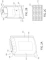
- FIGS.2A-2C depict a container 200 according to another embodiment of the invention.
- the container 200 is formed substantially similar to the container 100 except as described below.
- the cover 122 of FIGS.1A-1B is formed as a sleeve having front surface 127, back surface 128, bottom surface 7.7_.9
- cover 222 of FIGS.2A-2C is formed as an envelope having only a front surface 227 and a back surface 228 joined to one another at a lip 232.
- the lip 2.32. is formed substantially similarly as the lip 132.
- One or both of the front and back surfaces 227,228 may be formed with an enlarged surface area configured to conform to the size of a container body 202 received therein.
- a length L 1 of the front surface at a portion of the sleeve 222 housing the container body 202 may be greater than a length L 2 at the lower lip 132.
- the dimensions of the cover 222 may be modified as needed to conform to the dimensions of a container body 202 being received therein.
- shipping container 170 may receive a plurality of the covers 222 therein.
- the covers 222 may be formed as one integral insert similar to insert 180.
- the covers 122,222 of Figs.1A-1B and 2A-2C are at least partially compressible in one or more directions when subjected to external load to absorb at least a portion of an external force applied thereto.
- the combination of materials, shape and size of the covers 122,222 has been selected to permit the containers 100, 200 to deform under external forces which would otherwise result in a fracture or breakage of the container.
- This configuration has also been selected to strengthen the container 100,200 while avoiding the addition of any unnecessary bulk to the container, which would result in increased manufacturing and shipping costs.
- the result is a container 100,200 which exhibits substantially increased resistance to deformation, fracture and/or leakage when compared to prior art containers while minimizing production and shipping costs.
- the container 100,200 is capable of withstanding forces applied during shipping (e.g., from a warehouse, to a shipping carrier and ultimately to delivery address such as a home or business] and obviates the need for packaging within an additional shipping box. Further, the containers 100,200 offer the added advantage that they are capable of being shipped on their own without the use of any secondary packaging.
- the containers described herein may be used for the storage of any of a variety of liquid, gel, solid or semi-solid products such as toothpaste, oral care solutions, home cleaning products, soaps, fabric softeners, deodorants, lip treatments, etc. as well as for non-liquid products.
- any of the embodiments described herein may be modified to add or replace features of one embodiment with another.
- any of the embodiments described herein can be modified to be integrally formed onto a container body or be removably attached thereto.
- any of the protective features described herein may be combined into a container body to provide added protection. Any combination and modification of the components described herein is envisioned within the scope of the appended claims.
Landscapes
- Engineering & Computer Science (AREA)
- Mechanical Engineering (AREA)
- Chemical & Material Sciences (AREA)
- Composite Materials (AREA)
- Packages (AREA)
Claims (8)
- Behälter (100; 200), der umfasst:einen Behälterkörper (102) mit einem ersten Hohlraum zur Aufnahme eines Produkts, wobei der Behälterkörper (102) eine Vorderfläche (112), eine Rückfläche, eine erste Seitenwand (116) und eine zweite Seitenwand (118) aufweist; undeine Abdeckung (122; 222) mit einer Öffnung (124), die sich in sie hinein erstreckt, wobei die Öffnung (124) konfiguriert ist, den Behälterkörper (102) darin aufzunehmen, wobei die Abdeckung (122; 222) umfasst:eine Außenwand (142),eine Innenwand (144),einen zweiten Hohlraum (140), der zwischen der Außenwand (142) und der Innenwand (144) definiert ist, wobei der zweite Hohlraum (140) ein expandierbares Schutzmaterial (148) darin aufnimmt, undeinen fluiddurchlässigen Bereich (160), der an der Innenwand (144) vorgesehen ist, wobei der fluiddurchlässige Bereich (160) ein nicht-durchlässiges Material mit einer oder mehreren sich durch die Innenwand (144) erstreckenden Perforationen umfasst,wobei das Schutzmaterial (148) konfiguriert ist, die Abdeckung (122; 222) von einer ersten Konfiguration zu einer zweiten Konfiguration zu expandieren, wobei die erste Konfiguration einem ersten Innenprofil entspricht, das durch die Innenwand (144) definiert ist, und die zweite Konfiguration einem zweiten Innenprofil entspricht, das durch die Innenwand (144) definiert ist, wobei das zweite Innenprofil kleiner als das erste Innenprofil ist.
- Behälter nach Anspruch 1, wobei die erste Konfiguration einem ersten Außenprofil der Abdeckung (122; 122) entspricht und die zweite Konfiguration einem zweiten Außenprofil der Abdeckung (122; 122) entspricht, wobei das zweite Außenprofil größer als das erste Außenprofil ist.
- Behälter nach Anspruch 1, der ferner einen Anschluss (150) umfasst, der das Befüllen des zweiten Hohlraums (140) mit dem Schutzmaterial (148) ermöglicht.
- Behälter nach Anspruch 1, wobei das Schutzmaterial (148) ein expandierbarer Schaum oder ein expandierbares Gas ist.
- Behälter nach Anspruch 1, der ferner ein Einwegventil umfasst, das konfiguriert ist, einen Gasfluss in den zweiten Hohlraum (140) zu ermöglichen, wobei das Gas mit dem Schutzmaterial (148) reagiert, um das Schutzmaterial (148) von der ersten Konfiguration in die zweite Konfiguration zu bewegen.
- Behälter nach Anspruch 1, wobei das Schutzmaterial (148) absorbierend ist.
- Behälter nach Anspruch 1, wobei der Behälterkörper (102) mit der Abdeckung (122; 222) über einen oder mehrere der folgenden Mechanismen verriegelt ist: Klebstoff, Schweißung, Nut- und Feder-Mechanismus, Rastverschluss, Reibschluss, Keilsitz und eine Klappe, die sich von der Abdeckung (122; 222) und über eine obere Fläche des Behälterkörpers (102) erstreckt.
- Behälter nach Anspruch 1, der ferner eine Lippe (232) umfasst, die sich um zumindest einen Abschnitt eines Umfangs der Abdeckung (222) erstreckt, wobei eine Breite der Abdeckung (222) in einer ersten Höhe größer ist als eine Breite der Abdeckung (222) in einer zweiten Höhe, die sich an der Lippe (232) befindet.
Applications Claiming Priority (2)
| Application Number | Priority Date | Filing Date | Title |
|---|---|---|---|
| US15/848,980 US10654637B2 (en) | 2017-12-20 | 2017-12-20 | Expandable secondary package for a container |
| PCT/US2018/065448 WO2019125902A1 (en) | 2017-12-20 | 2018-12-13 | Expandable secondary package for a container |
Publications (2)
| Publication Number | Publication Date |
|---|---|
| EP3728069A1 EP3728069A1 (de) | 2020-10-28 |
| EP3728069B1 true EP3728069B1 (de) | 2024-01-31 |
Family
ID=64949469
Family Applications (1)
| Application Number | Title | Priority Date | Filing Date |
|---|---|---|---|
| EP18830124.6A Active EP3728069B1 (de) | 2017-12-20 | 2018-12-13 | Expandierbare sekundärverpackung für einen behälter |
Country Status (6)
| Country | Link |
|---|---|
| US (1) | US10654637B2 (de) |
| EP (1) | EP3728069B1 (de) |
| CN (1) | CN111448148B (de) |
| AU (1) | AU2018390463B2 (de) |
| MX (1) | MX2020006147A (de) |
| WO (1) | WO2019125902A1 (de) |
Families Citing this family (2)
| Publication number | Priority date | Publication date | Assignee | Title |
|---|---|---|---|---|
| CN111479757B (zh) * | 2017-12-21 | 2022-06-14 | 高露洁-棕榄公司 | 具有一体式保护特征的耐用容器 |
| CN120461953A (zh) * | 2025-04-29 | 2025-08-12 | 深圳光大同创新材料股份有限公司 | 一种用于电子产品的夹心复合材料面板 |
Family Cites Families (31)
| Publication number | Priority date | Publication date | Assignee | Title |
|---|---|---|---|---|
| GB838205A (en) | 1958-07-08 | 1960-06-22 | Samuel Kremner | Improvements in resilient pads and the like for use in packaging and upholstery |
| US3412521A (en) * | 1967-02-06 | 1968-11-26 | Dow Chemical Co | Method for packing articles |
| US3871521A (en) * | 1972-03-22 | 1975-03-18 | Continental Can Co | Shock-proof container and method for making same |
| BE822385A (fr) | 1973-11-29 | 1975-05-20 | Sac d'expedition renbourre et procede de fabrication | |
| US4240556A (en) * | 1978-02-23 | 1980-12-23 | Field Andrew Stewart | Inflatable package and method of manufacture |
| US4155453A (en) * | 1978-02-27 | 1979-05-22 | Ono Dan D | Inflatable grip container |
| US4620633A (en) * | 1985-09-30 | 1986-11-04 | Lookholder Theodore W | Protective envelope device for packaging fragile articles |
| US4756937A (en) * | 1987-04-30 | 1988-07-12 | Mentzer Elizabeth A | Protective barriers, receptacles, liners and packaging for containers of hazardous chemicals |
| US4836379A (en) * | 1987-07-08 | 1989-06-06 | Shaw William H | Modular shock-absorbing shipping pack |
| US4918904A (en) * | 1987-08-25 | 1990-04-24 | Pharo Daniel A | Method for forming clam-like packaging system |
| US5129519A (en) * | 1989-09-05 | 1992-07-14 | Minnesota Mining And Manufacturing Company | Packaging container |
| US5180060A (en) * | 1991-07-10 | 1993-01-19 | Jarvis Chemicals & Paper Company | Inflatable, encapsulating packaging insert |
| JP3259861B2 (ja) * | 1992-08-31 | 2002-02-25 | ジャサイ・ゾルタン・カズマー | 緩衝保護装置 |
| US5372429A (en) | 1992-10-13 | 1994-12-13 | Dow Corning Corporation | Sealable and reusable pouch |
| DK0676337T3 (da) * | 1994-04-05 | 1997-06-23 | Pillopak Bv | All-round-forsendelseslomme |
| US6139188A (en) * | 1999-04-29 | 2000-10-31 | Marzano; Domenico | Insulated transit bag |
| US6520333B1 (en) * | 2000-04-14 | 2003-02-18 | Michell Tschantz | Tubular inflatable packaging cushion with product pocket |
| US6755568B2 (en) | 2000-12-21 | 2004-06-29 | Cargo Technology, Inc. | Inflatable insulating liners for shipping containers and method of manufacture |
| ES2347773T3 (es) | 2001-12-19 | 2010-11-04 | Cryovac, Inc. | Envase que tiene un bastidor inflado. |
| US6910582B2 (en) * | 2002-05-22 | 2005-06-28 | Gary W. Lantz | Shock absorbing insulated shipping container especially for breakable glass bottles |
| FR2859185B1 (fr) * | 2003-08-29 | 2007-08-31 | Huhtamaki France Sa | Barquette absorbante avec ou sans barriere et procede de fabrication |
| CN2647958Y (zh) * | 2003-10-17 | 2004-10-13 | 吴达新 | 一种快速膨胀增重止水袋 |
| US7568324B2 (en) | 2004-11-24 | 2009-08-04 | Bussey Iii Buddy Harry | Cushioned package and method of making |
| JP4982478B2 (ja) | 2005-03-12 | 2012-07-25 | シールド エア コーポレーション(ユーエス) | 膨張式容器 |
| TWM287298U (en) * | 2005-09-28 | 2006-02-11 | Photon Formosa Co Ltd | Water-absorbing material |
| US7584848B2 (en) * | 2005-12-09 | 2009-09-08 | Air-Paq, Inc. | Structure of air-packing device |
| US9290313B2 (en) * | 2007-04-23 | 2016-03-22 | Coldkeepers, Llc | Insulated shipping bags |
| US20120000807A1 (en) * | 2009-03-13 | 2012-01-05 | Elizabeth Scarbrough | Inflatable, reusable and leak-resistant carrier |
| US8568029B2 (en) | 2009-05-05 | 2013-10-29 | Sealed Air Corporation (Us) | Inflatable mailer, apparatus, and method for making the same |
| WO2015171131A1 (en) * | 2014-05-07 | 2015-11-12 | Colgate-Palmolive Company | Oral care implement |
| JP6445281B2 (ja) | 2014-09-01 | 2018-12-26 | 克敏 吉房 | 気体クッション材 |
-
2017
- 2017-12-20 US US15/848,980 patent/US10654637B2/en active Active
-
2018
- 2018-12-13 EP EP18830124.6A patent/EP3728069B1/de active Active
- 2018-12-13 MX MX2020006147A patent/MX2020006147A/es unknown
- 2018-12-13 CN CN201880078076.2A patent/CN111448148B/zh active Active
- 2018-12-13 WO PCT/US2018/065448 patent/WO2019125902A1/en not_active Ceased
- 2018-12-13 AU AU2018390463A patent/AU2018390463B2/en active Active
Also Published As
| Publication number | Publication date |
|---|---|
| CN111448148A (zh) | 2020-07-24 |
| AU2018390463A1 (en) | 2020-07-30 |
| WO2019125902A1 (en) | 2019-06-27 |
| MX2020006147A (es) | 2020-08-13 |
| US20190185241A1 (en) | 2019-06-20 |
| EP3728069A1 (de) | 2020-10-28 |
| AU2018390463B2 (en) | 2021-06-24 |
| US10654637B2 (en) | 2020-05-19 |
| CN111448148B (zh) | 2022-08-23 |
Similar Documents
| Publication | Publication Date | Title |
|---|---|---|
| EP2437988B1 (de) | Flexibler bis steifer verpackungsartikel sowie verfahren zu seiner herstellung und verwendung | |
| US20110120899A1 (en) | Inflatable mailing package | |
| CN101238045B (zh) | 充气包装材料结构 | |
| CN105109824B (zh) | 多级缓冲充气包装装置 | |
| US20070012591A1 (en) | Inflatable space filler structure for container | |
| KR19990071812A (ko) | 팽창식 포장 쿠션 | |
| CN108860901B (zh) | 具有空气缓冲性能的包装盒及其应用 | |
| KR20170100471A (ko) | 장방형의 공기 포장 장치 및 그 제조 방법 | |
| EP3728056B1 (de) | Behälter mit integriertem schutzmerkmal | |
| EP3728069B1 (de) | Expandierbare sekundärverpackung für einen behälter | |
| CN111479757B (zh) | 具有一体式保护特征的耐用容器 | |
| US12515867B2 (en) | Fluid container with check valve | |
| ES2439013T3 (es) | Procedimiento y disposición para embalar al menos un artículo en un receptáculo, y pluralidad de tipos de receptáculo para expedir artículos | |
| JPH10129731A (ja) | 梱包容器および梱包容器用保護材 | |
| CA3149795A1 (en) | Inflatible packaging box | |
| WO2025128548A1 (en) | Inflatable reusable containers | |
| US6435348B1 (en) | Cushioned container assembly | |
| WO2009107225A1 (ja) | 空気緩衝材及び被梱包物搬送用鞄 | |
| WO2012173603A1 (en) | Protective packaging | |
| CN106081357B (zh) | 方形流体包装装置 | |
| NL2036168B1 (en) | Reusable transport enclosure comprising a mono-material laminate | |
| US11148866B2 (en) | Airbag with a hammock | |
| KR20240007434A (ko) | 포장캡 | |
| JP2000309362A (ja) | 弁及び袋状緩衝材 | |
| IT201800005023A1 (it) | Imballo e metodo di imballaggio di oggetti da spedire o trasportare. |
Legal Events
| Date | Code | Title | Description |
|---|---|---|---|
| STAA | Information on the status of an ep patent application or granted ep patent |
Free format text: STATUS: UNKNOWN |
|
| STAA | Information on the status of an ep patent application or granted ep patent |
Free format text: STATUS: THE INTERNATIONAL PUBLICATION HAS BEEN MADE |
|
| PUAI | Public reference made under article 153(3) epc to a published international application that has entered the european phase |
Free format text: ORIGINAL CODE: 0009012 |
|
| STAA | Information on the status of an ep patent application or granted ep patent |
Free format text: STATUS: REQUEST FOR EXAMINATION WAS MADE |
|
| 17P | Request for examination filed |
Effective date: 20200326 |
|
| AK | Designated contracting states |
Kind code of ref document: A1 Designated state(s): AL AT BE BG CH CY CZ DE DK EE ES FI FR GB GR HR HU IE IS IT LI LT LU LV MC MK MT NL NO PL PT RO RS SE SI SK SM TR |
|
| AX | Request for extension of the european patent |
Extension state: BA ME |
|
| DAV | Request for validation of the european patent (deleted) | ||
| DAX | Request for extension of the european patent (deleted) | ||
| STAA | Information on the status of an ep patent application or granted ep patent |
Free format text: STATUS: EXAMINATION IS IN PROGRESS |
|
| 17Q | First examination report despatched |
Effective date: 20220131 |
|
| GRAP | Despatch of communication of intention to grant a patent |
Free format text: ORIGINAL CODE: EPIDOSNIGR1 |
|
| STAA | Information on the status of an ep patent application or granted ep patent |
Free format text: STATUS: GRANT OF PATENT IS INTENDED |
|
| INTG | Intention to grant announced |
Effective date: 20230811 |
|
| GRAS | Grant fee paid |
Free format text: ORIGINAL CODE: EPIDOSNIGR3 |
|
| GRAA | (expected) grant |
Free format text: ORIGINAL CODE: 0009210 |
|
| STAA | Information on the status of an ep patent application or granted ep patent |
Free format text: STATUS: THE PATENT HAS BEEN GRANTED |
|
| P01 | Opt-out of the competence of the unified patent court (upc) registered |
Effective date: 20231219 |
|
| AK | Designated contracting states |
Kind code of ref document: B1 Designated state(s): AL AT BE BG CH CY CZ DE DK EE ES FI FR GB GR HR HU IE IS IT LI LT LU LV MC MK MT NL NO PL PT RO RS SE SI SK SM TR |
|
| REG | Reference to a national code |
Ref country code: GB Ref legal event code: FG4D Ref country code: CH Ref legal event code: EP |
|
| REG | Reference to a national code |
Ref country code: DE Ref legal event code: R096 Ref document number: 602018064785 Country of ref document: DE |
|
| REG | Reference to a national code |
Ref country code: IE Ref legal event code: FG4D |
|
| REG | Reference to a national code |
Ref country code: LT Ref legal event code: MG9D |
|
| REG | Reference to a national code |
Ref country code: NL Ref legal event code: MP Effective date: 20240131 |
|
| PG25 | Lapsed in a contracting state [announced via postgrant information from national office to epo] |
Ref country code: IS Free format text: LAPSE BECAUSE OF FAILURE TO SUBMIT A TRANSLATION OF THE DESCRIPTION OR TO PAY THE FEE WITHIN THE PRESCRIBED TIME-LIMIT Effective date: 20240531 |
|
| PG25 | Lapsed in a contracting state [announced via postgrant information from national office to epo] |
Ref country code: LT Free format text: LAPSE BECAUSE OF FAILURE TO SUBMIT A TRANSLATION OF THE DESCRIPTION OR TO PAY THE FEE WITHIN THE PRESCRIBED TIME-LIMIT Effective date: 20240131 |
|
| PG25 | Lapsed in a contracting state [announced via postgrant information from national office to epo] |
Ref country code: GR Free format text: LAPSE BECAUSE OF FAILURE TO SUBMIT A TRANSLATION OF THE DESCRIPTION OR TO PAY THE FEE WITHIN THE PRESCRIBED TIME-LIMIT Effective date: 20240501 |
|
| REG | Reference to a national code |
Ref country code: AT Ref legal event code: MK05 Ref document number: 1653743 Country of ref document: AT Kind code of ref document: T Effective date: 20240131 |
|
| PG25 | Lapsed in a contracting state [announced via postgrant information from national office to epo] |
Ref country code: RS Free format text: LAPSE BECAUSE OF FAILURE TO SUBMIT A TRANSLATION OF THE DESCRIPTION OR TO PAY THE FEE WITHIN THE PRESCRIBED TIME-LIMIT Effective date: 20240430 Ref country code: NL Free format text: LAPSE BECAUSE OF FAILURE TO SUBMIT A TRANSLATION OF THE DESCRIPTION OR TO PAY THE FEE WITHIN THE PRESCRIBED TIME-LIMIT Effective date: 20240131 Ref country code: HR Free format text: LAPSE BECAUSE OF FAILURE TO SUBMIT A TRANSLATION OF THE DESCRIPTION OR TO PAY THE FEE WITHIN THE PRESCRIBED TIME-LIMIT Effective date: 20240131 |
|
| PG25 | Lapsed in a contracting state [announced via postgrant information from national office to epo] |
Ref country code: ES Free format text: LAPSE BECAUSE OF FAILURE TO SUBMIT A TRANSLATION OF THE DESCRIPTION OR TO PAY THE FEE WITHIN THE PRESCRIBED TIME-LIMIT Effective date: 20240131 |
|
| PG25 | Lapsed in a contracting state [announced via postgrant information from national office to epo] |
Ref country code: AT Free format text: LAPSE BECAUSE OF FAILURE TO SUBMIT A TRANSLATION OF THE DESCRIPTION OR TO PAY THE FEE WITHIN THE PRESCRIBED TIME-LIMIT Effective date: 20240131 |
|
| PG25 | Lapsed in a contracting state [announced via postgrant information from national office to epo] |
Ref country code: RS Free format text: LAPSE BECAUSE OF FAILURE TO SUBMIT A TRANSLATION OF THE DESCRIPTION OR TO PAY THE FEE WITHIN THE PRESCRIBED TIME-LIMIT Effective date: 20240430 Ref country code: NO Free format text: LAPSE BECAUSE OF FAILURE TO SUBMIT A TRANSLATION OF THE DESCRIPTION OR TO PAY THE FEE WITHIN THE PRESCRIBED TIME-LIMIT Effective date: 20240430 Ref country code: NL Free format text: LAPSE BECAUSE OF FAILURE TO SUBMIT A TRANSLATION OF THE DESCRIPTION OR TO PAY THE FEE WITHIN THE PRESCRIBED TIME-LIMIT Effective date: 20240131 Ref country code: LT Free format text: LAPSE BECAUSE OF FAILURE TO SUBMIT A TRANSLATION OF THE DESCRIPTION OR TO PAY THE FEE WITHIN THE PRESCRIBED TIME-LIMIT Effective date: 20240131 Ref country code: IS Free format text: LAPSE BECAUSE OF FAILURE TO SUBMIT A TRANSLATION OF THE DESCRIPTION OR TO PAY THE FEE WITHIN THE PRESCRIBED TIME-LIMIT Effective date: 20240531 Ref country code: HR Free format text: LAPSE BECAUSE OF FAILURE TO SUBMIT A TRANSLATION OF THE DESCRIPTION OR TO PAY THE FEE WITHIN THE PRESCRIBED TIME-LIMIT Effective date: 20240131 Ref country code: GR Free format text: LAPSE BECAUSE OF FAILURE TO SUBMIT A TRANSLATION OF THE DESCRIPTION OR TO PAY THE FEE WITHIN THE PRESCRIBED TIME-LIMIT Effective date: 20240501 Ref country code: FI Free format text: LAPSE BECAUSE OF FAILURE TO SUBMIT A TRANSLATION OF THE DESCRIPTION OR TO PAY THE FEE WITHIN THE PRESCRIBED TIME-LIMIT Effective date: 20240131 Ref country code: ES Free format text: LAPSE BECAUSE OF FAILURE TO SUBMIT A TRANSLATION OF THE DESCRIPTION OR TO PAY THE FEE WITHIN THE PRESCRIBED TIME-LIMIT Effective date: 20240131 Ref country code: BG Free format text: LAPSE BECAUSE OF FAILURE TO SUBMIT A TRANSLATION OF THE DESCRIPTION OR TO PAY THE FEE WITHIN THE PRESCRIBED TIME-LIMIT Effective date: 20240131 Ref country code: AT Free format text: LAPSE BECAUSE OF FAILURE TO SUBMIT A TRANSLATION OF THE DESCRIPTION OR TO PAY THE FEE WITHIN THE PRESCRIBED TIME-LIMIT Effective date: 20240131 |
|
| PG25 | Lapsed in a contracting state [announced via postgrant information from national office to epo] |
Ref country code: PL Free format text: LAPSE BECAUSE OF FAILURE TO SUBMIT A TRANSLATION OF THE DESCRIPTION OR TO PAY THE FEE WITHIN THE PRESCRIBED TIME-LIMIT Effective date: 20240131 Ref country code: PT Free format text: LAPSE BECAUSE OF FAILURE TO SUBMIT A TRANSLATION OF THE DESCRIPTION OR TO PAY THE FEE WITHIN THE PRESCRIBED TIME-LIMIT Effective date: 20240531 |
|
| PG25 | Lapsed in a contracting state [announced via postgrant information from national office to epo] |
Ref country code: SE Free format text: LAPSE BECAUSE OF FAILURE TO SUBMIT A TRANSLATION OF THE DESCRIPTION OR TO PAY THE FEE WITHIN THE PRESCRIBED TIME-LIMIT Effective date: 20240131 Ref country code: PT Free format text: LAPSE BECAUSE OF FAILURE TO SUBMIT A TRANSLATION OF THE DESCRIPTION OR TO PAY THE FEE WITHIN THE PRESCRIBED TIME-LIMIT Effective date: 20240531 Ref country code: PL Free format text: LAPSE BECAUSE OF FAILURE TO SUBMIT A TRANSLATION OF THE DESCRIPTION OR TO PAY THE FEE WITHIN THE PRESCRIBED TIME-LIMIT Effective date: 20240131 Ref country code: LV Free format text: LAPSE BECAUSE OF FAILURE TO SUBMIT A TRANSLATION OF THE DESCRIPTION OR TO PAY THE FEE WITHIN THE PRESCRIBED TIME-LIMIT Effective date: 20240131 |
|
| PG25 | Lapsed in a contracting state [announced via postgrant information from national office to epo] |
Ref country code: DK Free format text: LAPSE BECAUSE OF FAILURE TO SUBMIT A TRANSLATION OF THE DESCRIPTION OR TO PAY THE FEE WITHIN THE PRESCRIBED TIME-LIMIT Effective date: 20240131 |
|
| PG25 | Lapsed in a contracting state [announced via postgrant information from national office to epo] |
Ref country code: SM Free format text: LAPSE BECAUSE OF FAILURE TO SUBMIT A TRANSLATION OF THE DESCRIPTION OR TO PAY THE FEE WITHIN THE PRESCRIBED TIME-LIMIT Effective date: 20240131 |
|
| PG25 | Lapsed in a contracting state [announced via postgrant information from national office to epo] |
Ref country code: CZ Free format text: LAPSE BECAUSE OF FAILURE TO SUBMIT A TRANSLATION OF THE DESCRIPTION OR TO PAY THE FEE WITHIN THE PRESCRIBED TIME-LIMIT Effective date: 20240131 Ref country code: EE Free format text: LAPSE BECAUSE OF FAILURE TO SUBMIT A TRANSLATION OF THE DESCRIPTION OR TO PAY THE FEE WITHIN THE PRESCRIBED TIME-LIMIT Effective date: 20240131 |
|
| PG25 | Lapsed in a contracting state [announced via postgrant information from national office to epo] |
Ref country code: SK Free format text: LAPSE BECAUSE OF FAILURE TO SUBMIT A TRANSLATION OF THE DESCRIPTION OR TO PAY THE FEE WITHIN THE PRESCRIBED TIME-LIMIT Effective date: 20240131 |
|
| PG25 | Lapsed in a contracting state [announced via postgrant information from national office to epo] |
Ref country code: SM Free format text: LAPSE BECAUSE OF FAILURE TO SUBMIT A TRANSLATION OF THE DESCRIPTION OR TO PAY THE FEE WITHIN THE PRESCRIBED TIME-LIMIT Effective date: 20240131 Ref country code: SK Free format text: LAPSE BECAUSE OF FAILURE TO SUBMIT A TRANSLATION OF THE DESCRIPTION OR TO PAY THE FEE WITHIN THE PRESCRIBED TIME-LIMIT Effective date: 20240131 Ref country code: RO Free format text: LAPSE BECAUSE OF FAILURE TO SUBMIT A TRANSLATION OF THE DESCRIPTION OR TO PAY THE FEE WITHIN THE PRESCRIBED TIME-LIMIT Effective date: 20240131 Ref country code: EE Free format text: LAPSE BECAUSE OF FAILURE TO SUBMIT A TRANSLATION OF THE DESCRIPTION OR TO PAY THE FEE WITHIN THE PRESCRIBED TIME-LIMIT Effective date: 20240131 Ref country code: DK Free format text: LAPSE BECAUSE OF FAILURE TO SUBMIT A TRANSLATION OF THE DESCRIPTION OR TO PAY THE FEE WITHIN THE PRESCRIBED TIME-LIMIT Effective date: 20240131 Ref country code: CZ Free format text: LAPSE BECAUSE OF FAILURE TO SUBMIT A TRANSLATION OF THE DESCRIPTION OR TO PAY THE FEE WITHIN THE PRESCRIBED TIME-LIMIT Effective date: 20240131 |
|
| REG | Reference to a national code |
Ref country code: DE Ref legal event code: R097 Ref document number: 602018064785 Country of ref document: DE |
|
| PG25 | Lapsed in a contracting state [announced via postgrant information from national office to epo] |
Ref country code: IT Free format text: LAPSE BECAUSE OF FAILURE TO SUBMIT A TRANSLATION OF THE DESCRIPTION OR TO PAY THE FEE WITHIN THE PRESCRIBED TIME-LIMIT Effective date: 20240131 |
|
| PLBE | No opposition filed within time limit |
Free format text: ORIGINAL CODE: 0009261 |
|
| STAA | Information on the status of an ep patent application or granted ep patent |
Free format text: STATUS: NO OPPOSITION FILED WITHIN TIME LIMIT |
|
| PG25 | Lapsed in a contracting state [announced via postgrant information from national office to epo] |
Ref country code: IT Free format text: LAPSE BECAUSE OF FAILURE TO SUBMIT A TRANSLATION OF THE DESCRIPTION OR TO PAY THE FEE WITHIN THE PRESCRIBED TIME-LIMIT Effective date: 20240131 |
|
| 26N | No opposition filed |
Effective date: 20241101 |
|
| PG25 | Lapsed in a contracting state [announced via postgrant information from national office to epo] |
Ref country code: SI Free format text: LAPSE BECAUSE OF FAILURE TO SUBMIT A TRANSLATION OF THE DESCRIPTION OR TO PAY THE FEE WITHIN THE PRESCRIBED TIME-LIMIT Effective date: 20240131 |
|
| PG25 | Lapsed in a contracting state [announced via postgrant information from national office to epo] |
Ref country code: MC Free format text: LAPSE BECAUSE OF FAILURE TO SUBMIT A TRANSLATION OF THE DESCRIPTION OR TO PAY THE FEE WITHIN THE PRESCRIBED TIME-LIMIT Effective date: 20240131 |
|
| REG | Reference to a national code |
Ref country code: CH Ref legal event code: PL |
|
| PG25 | Lapsed in a contracting state [announced via postgrant information from national office to epo] |
Ref country code: LU Free format text: LAPSE BECAUSE OF NON-PAYMENT OF DUE FEES Effective date: 20241213 |
|
| REG | Reference to a national code |
Ref country code: BE Ref legal event code: MM Effective date: 20241231 |
|
| PG25 | Lapsed in a contracting state [announced via postgrant information from national office to epo] |
Ref country code: BE Free format text: LAPSE BECAUSE OF NON-PAYMENT OF DUE FEES Effective date: 20241231 |
|
| PG25 | Lapsed in a contracting state [announced via postgrant information from national office to epo] |
Ref country code: CH Free format text: LAPSE BECAUSE OF NON-PAYMENT OF DUE FEES Effective date: 20241231 |
|
| PG25 | Lapsed in a contracting state [announced via postgrant information from national office to epo] |
Ref country code: IE Free format text: LAPSE BECAUSE OF NON-PAYMENT OF DUE FEES Effective date: 20241213 |
|
| PGFP | Annual fee paid to national office [announced via postgrant information from national office to epo] |
Ref country code: GB Payment date: 20251229 Year of fee payment: 8 |
|
| PGFP | Annual fee paid to national office [announced via postgrant information from national office to epo] |
Ref country code: FR Payment date: 20251226 Year of fee payment: 8 |
|
| PGFP | Annual fee paid to national office [announced via postgrant information from national office to epo] |
Ref country code: DE Payment date: 20251229 Year of fee payment: 8 |