EP3728022B1 - Flugzeugtüröffnungssystem - Google Patents
Flugzeugtüröffnungssystem Download PDFInfo
- Publication number
- EP3728022B1 EP3728022B1 EP18830419.0A EP18830419A EP3728022B1 EP 3728022 B1 EP3728022 B1 EP 3728022B1 EP 18830419 A EP18830419 A EP 18830419A EP 3728022 B1 EP3728022 B1 EP 3728022B1
- Authority
- EP
- European Patent Office
- Prior art keywords
- door
- lintel
- levers
- fuselage
- type
- Prior art date
- Legal status (The legal status is an assumption and is not a legal conclusion. Google has not performed a legal analysis and makes no representation as to the accuracy of the status listed.)
- Active
Links
- 244000261422 Lysimachia clethroides Species 0.000 claims description 5
- 238000009413 insulation Methods 0.000 claims description 5
- 230000008878 coupling Effects 0.000 claims description 3
- 238000010168 coupling process Methods 0.000 claims description 3
- 238000005859 coupling reaction Methods 0.000 claims description 3
- 238000009432 framing Methods 0.000 claims description 3
- 230000007246 mechanism Effects 0.000 description 10
- 230000003993 interaction Effects 0.000 description 3
- 230000006978 adaptation Effects 0.000 description 2
- 230000008901 benefit Effects 0.000 description 2
- 230000010354 integration Effects 0.000 description 2
- 241000272517 Anseriformes Species 0.000 description 1
- 238000010344 co-firing Methods 0.000 description 1
- 238000002788 crimping Methods 0.000 description 1
- 230000004927 fusion Effects 0.000 description 1
- 238000009434 installation Methods 0.000 description 1
- 238000002955 isolation Methods 0.000 description 1
- 238000000034 method Methods 0.000 description 1
- 230000035515 penetration Effects 0.000 description 1
- 238000004513 sizing Methods 0.000 description 1
- 238000003466 welding Methods 0.000 description 1
Images


Classifications
-
- B—PERFORMING OPERATIONS; TRANSPORTING
- B64—AIRCRAFT; AVIATION; COSMONAUTICS
- B64C—AEROPLANES; HELICOPTERS
- B64C1/00—Fuselages; Constructional features common to fuselages, wings, stabilising surfaces or the like
- B64C1/14—Windows; Doors; Hatch covers or access panels; Surrounding frame structures; Canopies; Windscreens accessories therefor, e.g. pressure sensors, water deflectors, hinges, seals, handles, latches, windscreen wipers
- B64C1/1407—Doors; surrounding frames
- B64C1/1415—Cargo doors, e.g. incorporating ramps
-
- B—PERFORMING OPERATIONS; TRANSPORTING
- B64—AIRCRAFT; AVIATION; COSMONAUTICS
- B64C—AEROPLANES; HELICOPTERS
- B64C1/00—Fuselages; Constructional features common to fuselages, wings, stabilising surfaces or the like
- B64C1/14—Windows; Doors; Hatch covers or access panels; Surrounding frame structures; Canopies; Windscreens accessories therefor, e.g. pressure sensors, water deflectors, hinges, seals, handles, latches, windscreen wipers
- B64C1/1407—Doors; surrounding frames
- B64C1/1423—Passenger doors
- B64C1/143—Passenger doors of the plug type
-
- B—PERFORMING OPERATIONS; TRANSPORTING
- B64—AIRCRAFT; AVIATION; COSMONAUTICS
- B64C—AEROPLANES; HELICOPTERS
- B64C1/00—Fuselages; Constructional features common to fuselages, wings, stabilising surfaces or the like
- B64C1/14—Windows; Doors; Hatch covers or access panels; Surrounding frame structures; Canopies; Windscreens accessories therefor, e.g. pressure sensors, water deflectors, hinges, seals, handles, latches, windscreen wipers
- B64C1/1407—Doors; surrounding frames
- B64C1/1461—Structures of doors or surrounding frames
-
- B—PERFORMING OPERATIONS; TRANSPORTING
- B64—AIRCRAFT; AVIATION; COSMONAUTICS
- B64C—AEROPLANES; HELICOPTERS
- B64C1/00—Fuselages; Constructional features common to fuselages, wings, stabilising surfaces or the like
- B64C1/22—Other structures integral with fuselages to facilitate loading, e.g. cargo bays, cranes
-
- E—FIXED CONSTRUCTIONS
- E05—LOCKS; KEYS; WINDOW OR DOOR FITTINGS; SAFES
- E05D—HINGES OR SUSPENSION DEVICES FOR DOORS, WINDOWS OR WINGS
- E05D7/00—Hinges or pivots of special construction
- E05D7/009—Elongate hinges, e.g. piano-hinges
-
- E—FIXED CONSTRUCTIONS
- E05—LOCKS; KEYS; WINDOW OR DOOR FITTINGS; SAFES
- E05Y—INDEXING SCHEME ASSOCIATED WITH SUBCLASSES E05D AND E05F, RELATING TO CONSTRUCTION ELEMENTS, ELECTRIC CONTROL, POWER SUPPLY, POWER SIGNAL OR TRANSMISSION, USER INTERFACES, MOUNTING OR COUPLING, DETAILS, ACCESSORIES, AUXILIARY OPERATIONS NOT OTHERWISE PROVIDED FOR, APPLICATION THEREOF
- E05Y2900/00—Application of doors, windows, wings or fittings thereof
- E05Y2900/50—Application of doors, windows, wings or fittings thereof for vehicles
- E05Y2900/502—Application of doors, windows, wings or fittings thereof for vehicles for aircraft or spacecraft
Definitions
- the invention relates to an aircraft auxiliary door opening system comprising a mechanism mounted on the fuselage of the aircraft and consisting of articulated links forming articulated quadrilaterals between the door and the fuselage.
- auxiliary doors As opposed to the “passenger” doors for embarkation / disembarkation of commercial aircraft passengers, of significantly more complex design (sizing, weight, integration of slides, massive horizontal articulation arm, etc.).
- the opening of an aircraft door for example a passenger or auxiliary door
- unlocking and releasing a safety catch lifting and pivoting of the carried by actuators around an axis of rotation.
- lifting and pivoting of the carried by actuators around an axis of rotation For closing, these movements follow one another in reverse kinematics.
- the auxiliary doors are equipped either with an arm articulated on the fuselage, the arm being linked to the door by a mechanism for releasing stops by translation, or by a hinge.
- the hinges of the “overwing” type doors are of the articulated arm type and allow the stops to be disengaged.
- the rigid hinge of the "piano hinge” type, between the fuselage and the door, requires an independent mechanism responsible for releasing the fuselage fittings. Such a piano hinge classically equips cargo doors.
- Rigid aircraft door opening hinges are disclosed, for example, in patent documents US6276026 , US2007257151 , Where US2016083071 .
- a seal between the door and the aircraft fuselage is for example described in the patent US 20090095841 .
- the piano hinge has the advantage of requiring little space but on the other hand requires an adaptable cover gasket if the hinges are not to be exposed to the air flow.
- the rigid connection between the fuselage and the door generates high level interaction forces during deformations of the fuselage in flight. These forces are inserted into the door and alter its structure.
- the installation of a rigid hinge requires high precision both in connection with the fuselage and with the door.
- these rigid hinges have an outer face mounted so that it is not flush with the outer skin of the fuselage, which disrupts the aerodynamics of this zone during penetration into the air.
- patent document US 20170183079 discloses an aircraft door connection assembly on a fuselage section including a main double hinge connected to the fuselage section and a link assembly between the door and the main hinge.
- This assembly incorporating an element connected to the door by sliding and pivoting.
- Such assembly allows the door to be moved up and in by pivoting around a virtual pivot point.
- such an assembly with two identical side hinges has the same limitations as that of the document US 5031863 previously cited.
- the invention aims to eliminate these drawbacks with the aid of a door hinge comprising a connecting set with articulated levers forming between them geometric configurations with evolving quadrilaterals during the door opening kinematics.
- These configurations allow “buoyancy” of the door relative to the fuselage, the term buoyancy signifies instantaneous adaptation, without causing stress, of the hinge by the establishment of flexible links operated by the combination of levers.
- Such buoyancy thus eliminates the interaction forces of the rigid hinges, while making it possible to simplify their assembly.
- all the links being integrated into the fuselage the aerodynamics of the aircraft is no longer disturbed.
- the present invention relates to a system for opening an aircraft auxiliary door in a fuselage, the door and the fuselage having skins in the continuation of one another.
- This system comprises a lintel for framing the auxiliary door integrated into the fuselage and an upper beam of the door structure placed opposite the lintel.
- this system includes a set of at least three lever links extending transversely to the door and fuselage skins to form a door-to-lintel coupling.
- Each link is connected, on the one hand, to said lintel by a fixed lever articulation relative to the fuselage and, on the other hand, to said upper beam by a movable lever articulation in pivoting with the door when it is opened, the joints being formed at the end of the levers and connected respectively to the lintel and to the upper beam by fixing means.
- the set of links comprises a first and a second type of link mounted alternately. In two successive types of connection, the pivoting movable joints and the fixed joints are positioned head-to-tail, so that the movable and fixed joints of two levers adjacent ones form an evolving quadrilateral which controls the door opening kinematics while maintaining flexible articulation between the lintel and the upper beam.
- the lever mechanism articulated according to articulated quadrilaterals allows buoyancy and adaptability between the fuselage and the door, which eliminates the interaction forces of the fuselage on the door.
- this mechanism makes it possible to significantly reduce the number of parts for the functions of positioning the door in its frame when it is closed, to increase the resistance to internal pressure during the flight phase, to facilitate the piloting of the door. kinematics of the door during opening, and maintaining the door in the open position.
- the qualifiers “upper” and “lower” refer to standard relative locations of elements, when the airplane is on the ground.
- the qualifier “longitudinal” refers to the direction of the main extension of an element.
- “Front” and “rear” refer to locations respectively on the side furthest from the skin of the fuselage, that is to say inside a passenger cabin of the aircraft, and on the side closer to the body. the internal skin of the fuselage, therefore close to the internal wall of this cabin.
- Transversal denotes an expanse in a plane perpendicular to the longitudinal direction of the fuselage and “lateral” an expanse seen in a transverse plane.
- the qualifiers “outside” and “inside” refer to locations outside and in the airplane.
- FIG. 1a and 1b illustrate, inside an airplane passenger cabin, an example according to the invention of an auxiliary door opening system 10 provided with a skin 20 integrated in a cutout 3d of the fuselage skin 30.
- the door and the fuselage are not shown in volume and can be assimilated, for understanding, to their skins 20 and 30.
- the system 10 comprises a lintel 11 for the upper frame of the door 20.
- This lintel 11 is integrated into the fuselage by fixing, on the internal face 30i of the fuselage skin 30, its rear longitudinal face 11a by any known means (welding , bonding, thermal fusion, crimping, co-firing, etc.).
- the opening system 10 couples the door 20 to the lintel 11.
- Said door 20 has an internal framing structure composed of an upper beam 2S, arranged opposite the lintel 11, two side beams 2L and a lower beam (not visible) parallel to the upper beam 2S.
- the door 20 is held in the closed position by immobilization means conventionally attached to the lower beam.
- the coupling mechanism 40 consists of a set of three lever links 4A, 4B and 4C between the lintel 11 and the upper beam 2S extending transversely, that is to say substantially parallel to the beams. side 2L as well as perpendicular to the door skins 20 and fuselage 30.
- the lever links 4A and 4C, which surround the central lever link 4B, are identical and are said to be of the first type. They are connected to the lintel 11 by fixing identical fittings 41 extending, at right angles, on its front longitudinal face 11b parallel to its rear face 11a, and on its lower longitudinal face 11c perpendicular to the front 11b and rear faces 11a.
- the levers 4A and 4C are connected to the upper beam 2S of the door 20 by other identical fittings 42, in "gooseneck" in the example illustrated, fixed to the upper face 2a of the upper beam 2S. .
- Each lever 4A or 4C of the links of the first type has in this example two parallel, rectilinear and identical fins 4u which, at their opposite ends, form two joints: a joint 5a in axial rotation with one end of the fitting 41 which engages between the two fins 4u, and a hinge 5b in axial rotation with one end of the fitting 42 which also engages between the two fins 4u.
- the end joints 5a connect the levers 4A and 4C to the lintel 11 in a fixed manner, while the end joints 5b connect the levers 4A and 4C to the upper beam 2S in a movable manner, in pivoting with the door 20.
- the joints 5a and 5b are aligned respectively on a fixed axis of rotation A'A and a mobile axis of rotation B'B, parallel to the door skins 20 and of the fuselage 30.
- the mobile axis of rotation B'B and therefore the joints 5b, remain close to the internal face 30i of the fuselage skin 30 while the fixed axis of rotation A'A, and therefore the joints 5a, remain further away and at a constant distance from this internal face 30i.
- this lever 4B is connected to the lintel 11 by a fitting 43 fixed to the lower face 11c of the lintel 11 and to the upper beam 2S by a fitting 44 extending, at right angles, on the upper face 2a and on the front face 2b of the upper beam 2S.
- the central lever 4B here has two fins 4v of generally curved side profile, turned towards the upper door beam 2S, and connected by a central bridge 4p giving an "H" shape to this central lever 4B.
- two joints are also formed: a joint 6a in axial rotation with one end of the fitting 43 which extends between the two ends of ailerons 4v, and a joint 6b in axial rotation with one end of the fitting 44 which also extends between the two fins 4v.
- the end articulation 6a connects the central lever 4B to the lintel 11 in a fixed manner via the fitting 43, while the end articulation 6b connects this central lever 4B in pivoting with the door 20 via the fitting 44.
- each pair of adjacent levers has joints 5a, 5b, 6a and 6b forming a quadrilateral with two opposite joints 5a and 6a fixed relative to the lintel 11 (and therefore to the fuselage 30), to which they are connected by the fittings 41 and 43, and with two opposite joints 5b and 6b movable in pivoting with the upper beam 2S (and therefore with the door), to which they are connected by fittings 42 and 44.
- the internal face of the fuselage 30i advantageously has an insulation panel 31 extending from an end zone of skin 3e of the fuselage 30, by shifting in front of the fuselage cutout 3d and up to to come to rest on a door seal 2j which runs along the periphery 21 of the door skin 20.
- a mass compensation system 50 useful during door opening is advantageously mounted in the extension of the central lever 4B.
- This assembly is carried out between the upper beam 2S and a support arm 53 fixed parallel to the upper beam 2S, between the side beams 2L.
- the central lever 4B having a greater amplitude of angular movement than the Other compared to the door 20, the compensation system 50 then has a shorter stroke, which makes it possible to reduce the stroke of the mass compensation.
- the fitting 44 is extended by a longitudinal extension 44e which is fixed at the end on the support arm 53.
- a cylindrical stiffening bar 7 (which does not appear on the figure 1b for reasons of visibility) connects, parallel to the upper beam 2S, the articulations 5a of the levers 4A and 4C of the first type of connection which are furthest from the internal face of the fuselage 30i.
- the geometric axis of this bar 7 coincides with the axis A'A of fixed rotation of the joints 5a.
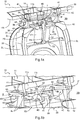
- FIGS of figures 2a and 2b respectively illustrate, from another angle, the position of the lever links of the first type, 4A or 4C, and the position of the lever linkage of the second type 4B, when the door is in the closed position in the cutout 3d of the skin of fuselage 30.
- FIG. 1 it appears more precisely the connection between the insulation panel 31 and the skin end zone 3e of the fuselage 30, as well as the support of this panel 31 on the seal 2j of the door.
- the side view of the figure 2b also shows that the end articulation 6a of the central lever 4B is fixedly connected to the lintel 11 via the fitting 43, and that the end articulation 6b of this central lever 4B, connected to the upper beam 2S via the fitting 44, will be able to drive the lever 4B in pivoting with the door 20 around the other end 6a.
- the kinematics of opening of the door 20 by the system 10 is illustrated by the perspective views of the figures 3a to 3c , door 20 being seen partially transparent through the fuselage skin 30.
- the door Before opening, the door is held in the closed position by immobilization means attached to the lower beam of the door structure (not visible), in particular a rigid holding mechanism of the type. “C-latch” lock (“C” for cylindrical) unlocking controlled by the opening handle.
- the lever links 4A to 4C ensure the opening of the door by pivoting around the lintel 11.
- the quadrilaterals having the articulations 5a, 5b, 6a and 6b as their vertices are deformed. with the variable position of the opposing joints 5b and 6b, while the position of the other opposing joints 5a and 6a is fixed.
- the position of the joints 5a, 5b, 6a and 6b thus control the door opening kinematics, while allowing a certain “buoyancy” or flexibility of adaptation to the connections between the upper beam 2S and the lintel 11.
- the door 20 reaches its maximum open position. This position is maintained by known locking means - jaws, hooks, stops - or by the pressure exerted by the jacks 51 and 52 (cf. figures 1a Where 3a ) which form the mass compensation system during opening by exerting suitable pressure.
- FIGS. 4a and 4b also illustrate, respectively at the level of the lever connections of the first type, 4A or 4C, and at the level of the central lever connection of the second type 4B, the configuration of the opening system 10 when the door 20 is in the open position maximum.
- this bypass is advantageously achieved by the gooseneck shape of the fittings 42 ( figure 4a ); in the case of the lever of the second type of link 4B ( figure 4b ), this bypass is achieved by the shape of the curved profile of this lever 4B between the fittings 43 and 44, fixed to the lintel 11 and the upper door beam 2S.
- the mass compensation system can include one or more than two jacks which can be installed as an extension of the central lever or other levers.
- the upper face of the upper beam of the door structure may not be perpendicular to the door skin.
- the front face of the upper beam or the lintel may not be parallel to the door or fuselage skin.
- Other types of fittings and other fixing methods can be provided, including integration into the door sill.
- the fittings are modified so that the axis of rotation AA 'remains parallel to the axis of the desired hinge (generally according to the cutout of the panel), and that the joints of the first and second type of connection debate in parallel planes.
- the door locking system in the open position is installed on a lever of the first type of connection, on the fuselage side or on the door side, or on a lever of the second type of connection, in particular on the central lever of the second.
- type of linkage in the case of a linkage set with three levers this locking system then being able to be mounted either by means of the compensation system or between the lever and the fuselage.
- the profile of the fittings and the levers is adapted to allow the fuselage to be bypassed during the opening of the door and may adopt, in addition to the shapes described above, any suitable curved or concave shape.
- the links of the two types can be centered on a link of the first or of the second type.
Landscapes
- Engineering & Computer Science (AREA)
- Mechanical Engineering (AREA)
- Aviation & Aerospace Engineering (AREA)
- Hinges (AREA)
- Power-Operated Mechanisms For Wings (AREA)
- Wing Frames And Configurations (AREA)
- Tents Or Canopies (AREA)
Claims (11)
- System zur Öffnung (10) einer Flugzeughilfstür (20) in einem Rumpf, wobei die Tür und der Rumpf Häute (20, 30) in der Verlängerung voneinander aufweisen, wobei das System (10) einen Sturz (11) zur Einrahmung der Hilfstür aufweist, der in den Rumpf integriert ist, und einen oberen Türstrukturpfosten (2S), der gegenüber dem Sturz (11) angeordnet ist, dadurch gekennzeichnet, dass das System einen Satz von mindestens drei Verbindungen mit Hebeln (4A, 4B, 4C) aufweist, die sich quer zu den Tür-(20) und Rumpf- (30) Häuten erstrecken, um eine Kopplung der Tür (20) an den Sturz (11) zu bilden, dadurch, dass jede Verbindung einerseits durch ein Hebelgelenk (5a, 6a), das bezogen auf den Rumpf (30) fest ist, mit dem Sturz (11) und andererseits durch ein Gelenk des Hebels, das mit der Tür (20) bei deren Öffnung schwenkbeweglich ist (5b, 6b), mit dem oberen Pfosten (2S) verbunden ist, wobei die Gelenke (5a, 5b; 6a, 6b) am Ende der Hebel (4A, 4C; 4B) ausgebildet und jeweils durch Befestigungsmittel (41, 43; 42, 44) an den Sturz (11) und an den oberen Pfosten (2S) angeschlossen sind, und dadurch, dass der Satz von Verbindungen einen aufeinanderfolgenden ersten und zweiten Verbindungstyp aufweist, die abwechselnd angebracht sind, wobei die schwenkbeweglichen Gelenke (5b, 6b) und die festen Gelenke (5a, 6a) gegenüberliegend positioniert sind, so dass die beweglichen und festen Gelenke (5b, 5a; 6b, 6a) zweier benachbarter Hebel (4A, 4B; 4B, 4C) ein veränderliches Viereck bilden, das die Öffnungskinematik der Tür (20) steuert, wobei eine Gelenkbeweglichkeit zwischen dem Sturz (11) und dem oberen Pfosten (2S) beibehalten wird.
- Öffnungssystem nach Anspruch 1, wobei, der obere Türstrukturpfosten (2S) aufweisend eine Oberseite (2a), die senkrecht zur Türhaut (20) verläuft, ein Beschlag (42) als Befestigungsmittel, der die Gelenke (5b) der Hebel (4A, 4C) des ersten Verbindungstyps mit dem oberen Pfosten (2S) verbindet, eine Befestigungsbasis aufweist, die sich auf der Oberseite (2a) des Pfostens (2S) erstreckt.
- Öffnungssystem nach einem der Ansprüche 1 oder 2, wobei, der Sturz (11) aufweisend eine Unterseite (11c), die senkrecht zur Rumpfhaut (30) verläuft, und eine Vorderseite (11b), die parallel zur Rumpfhaut (30) verläuft, ein Beschlag (41) als Befestigungsmittel, der die Gelenke der Hebel (4A, 4C) des ersten Verbindungstyps mit dem Sturz (11) verbindet, eine winkelige Befestigungsseite zum Teil auf der Unterseite (11c) und zum Teil auf der Vorderseite (11a) des Sturzes (11) aufweist.
- Öffnungssystem nach einem der Ansprüche 2 oder 3, wobei, der obere Türstrukturpfosten (2S) aufweisend eine Vorderseite (2b), die parallel zur Türhaut (20) und senkrecht zur Oberseite (2a) des Pfostens (2S) verläuft, ein Beschlag (44) als Befestigungsmittel, der die Gelenke (6b) der Hebel (4B) des zweiten Verbindungstyps mit dem oberen Türstrukturpfosten (2S) verbindet, zum Teil auf der Oberseite (2a) und zum Teil auf der Vorderseite (2b) des oberen Pfostens (2S) befestigt ist.
- Öffnungssystem nach einem der Ansprüche 3 oder 4, wobei ein Beschlag (43) als Befestigungsmittel, der die Gelenke (6a) der Hebel (4B) des zweiten Verbindungstyps mit dem Sturz (11) verbindet, eine Befestigungsbasis aufweist, die sich auf der Unterseite (11c) des Pfostens (11) erstreckt.
- Öffnungssystem nach einem der vorhergehenden Ansprüche, wobei der Satz von Verbindungen drei Hebel (4A, 4B, 4C) aufweist, wobei zwei Hebel des ersten Verbindungstyps (4A, 4C) einen mittleren Hebel des zweiten Typs (4B) umgeben.
- Öffnungssystem nach einem der vorhergehenden Ansprüche, wobei sich eine Isolationsplatte (31) von einem Endbereich (3e) der Rumpfhaut (30) erstreckt und diese Platte (31) vor diesem Bereich (3e) auf einer Türdichtung (2j) aufliegt, wenn sich die Tür (20) in geschlossener Position befindet.
- Öffnungssystem nach einem der vorhergehenden Ansprüche, wobei ein Massenausgleichssystem (50) in der Tür (20) in Verlängerung mindestens eines der Hebel (4B) eingebaut ist.
- Öffnungssystem nach dem vorhergehenden Anspruch, dadurch gekennzeichnet, dass das Ausgleichssystem (50) mindestens einen Zylinder (51, 52) aufweist, der in Verlängerung mindestens eines Hebels (4A bis 4B) angeordnet ist, des mittleren Hebels (4B) im Falle eines Satzes von Verbindungen mit drei Hebeln nach Anspruch 6.
- Öffnungssystem nach einem der vorhergehenden Ansprüche, wobei die Beschläge (42), die auf dem oberen Türpfosten (2S) befestigt und mit den Gelenken (5b) der Hebel (4A, 4C) des ersten Verbindungstyps verbunden sind, eine Schwanenhalsform aufweisen, während die Hebel (4B) des zweiten Verbindungstyps ein seitliches Profil mit gekrümmter Form aufweisen, die zum oberen Türpfosten (2S) gewandt ist.
- Öffnungssystem nach einem der vorhergehenden Ansprüche, wobei eine Versteifungsstange (7) parallel zum Sturz (11) die Gelenke (5a) der Hebel (4A, 4C) des ersten Verbindungstyps verbindet, die am weitesten von der Haut des Rumpfs (30) entfernt sind.
Applications Claiming Priority (2)
| Application Number | Priority Date | Filing Date | Title |
|---|---|---|---|
| FR1762409A FR3075166B1 (fr) | 2017-12-19 | 2017-12-19 | Systeme d'ouverture de porte d'avion a quadrilateres |
| PCT/EP2018/084801 WO2019121337A1 (fr) | 2017-12-19 | 2018-12-13 | Systeme d'ouverture de porte d'avion |
Publications (2)
| Publication Number | Publication Date |
|---|---|
| EP3728022A1 EP3728022A1 (de) | 2020-10-28 |
| EP3728022B1 true EP3728022B1 (de) | 2021-09-15 |
Family
ID=61132749
Family Applications (1)
| Application Number | Title | Priority Date | Filing Date |
|---|---|---|---|
| EP18830419.0A Active EP3728022B1 (de) | 2017-12-19 | 2018-12-13 | Flugzeugtüröffnungssystem |
Country Status (6)
| Country | Link |
|---|---|
| US (1) | US11465730B2 (de) |
| EP (1) | EP3728022B1 (de) |
| BR (1) | BR112020012109A2 (de) |
| CA (1) | CA3085530A1 (de) |
| FR (1) | FR3075166B1 (de) |
| WO (1) | WO2019121337A1 (de) |
Family Cites Families (15)
| Publication number | Priority date | Publication date | Assignee | Title |
|---|---|---|---|---|
| US4510714A (en) * | 1982-09-30 | 1985-04-16 | The Boeing Company | Powered outward-opening cargo door |
| US4720065A (en) * | 1985-01-24 | 1988-01-19 | The Boeing Company | Translatable outward opening plug-type aircraft door and actuating mechanisms therefor |
| US5031863A (en) * | 1989-12-21 | 1991-07-16 | The Boeing Company | Upward/outward opening, plug-type overwing emergency exit hatch |
| US5064147A (en) * | 1990-02-12 | 1991-11-12 | The Boeing Company | Upwardly opening plug-type door for use as an over-wing emergency hatch |
| US6276026B1 (en) | 1997-03-10 | 2001-08-21 | The Boeing Company | Aircraft hinge |
| US5931415A (en) * | 1997-05-09 | 1999-08-03 | The Boeing Company | Plug-type overwing emergency exit door assembly |
| FR2819782B1 (fr) * | 2001-01-25 | 2003-04-11 | Eads Airbus Sa | Dispositif d'articulation d'un battant de porte d'aeronef et porte d'aeronef integrant un tel dispositif |
| US6877695B2 (en) | 2002-12-13 | 2005-04-12 | The Boeing Company | Hinge cover integration into door seal edges |
| DE102004034903A1 (de) | 2004-07-19 | 2006-02-16 | Airbus Deutschland Gmbh | Abdeckungseinrichtung für ein Scharnier eines Flugzeugs |
| GB0619615D0 (en) * | 2006-10-04 | 2006-11-15 | Airbus Uk Ltd | A door for opening and closing a door aperture in an aircraft |
| CN104144851B (zh) * | 2012-02-29 | 2017-05-17 | 庞巴迪公司 | 用于飞机舱门的连接组件 |
| FR3006995B1 (fr) * | 2013-06-14 | 2017-03-17 | Latecoere | Procede d'armement / desarmement de toboggan de porte d'avion et mecanisme de mise en oeuvre |
| US9592902B2 (en) * | 2014-02-17 | 2017-03-14 | The Boeing Company | Hatch assembly for use in a vehicle and method of assembling the same |
| EP3000720B1 (de) | 2014-09-23 | 2019-06-19 | AIRBUS HELICOPTERS DEUTSCHLAND GmbH | Flugzeugtürbetätigungssystem |
| EP3323709B1 (de) * | 2016-11-16 | 2019-01-02 | AIRBUS HELICOPTERS DEUTSCHLAND GmbH | Betätigbare notausgangstür und luft- oder raumfahrzeug mit einer unter druck stehenden kabine mit solch einer betätigbaren notausgangstür |
-
2017
- 2017-12-19 FR FR1762409A patent/FR3075166B1/fr not_active Expired - Fee Related
-
2018
- 2018-12-13 EP EP18830419.0A patent/EP3728022B1/de active Active
- 2018-12-13 US US16/771,874 patent/US11465730B2/en active Active
- 2018-12-13 WO PCT/EP2018/084801 patent/WO2019121337A1/fr unknown
- 2018-12-13 CA CA3085530A patent/CA3085530A1/fr active Pending
- 2018-12-13 BR BR112020012109-6A patent/BR112020012109A2/pt active IP Right Grant
Also Published As
| Publication number | Publication date |
|---|---|
| US20210179253A1 (en) | 2021-06-17 |
| US11465730B2 (en) | 2022-10-11 |
| WO2019121337A1 (fr) | 2019-06-27 |
| FR3075166B1 (fr) | 2019-12-27 |
| EP3728022A1 (de) | 2020-10-28 |
| CA3085530A1 (fr) | 2019-06-27 |
| BR112020012109A2 (pt) | 2021-03-30 |
| FR3075166A1 (fr) | 2019-06-21 |
Similar Documents
| Publication | Publication Date | Title |
|---|---|---|
| EP3863921B1 (de) | Verfahren zum öffnen/schliessen einer flugzeugtür und flugzeug mit einem solchen verfahren | |
| EP3983289B1 (de) | Flugzeugtür mit einer vorrichtung zur fixierung der türauslegerarme | |
| US6595574B2 (en) | Removable vehicle roof | |
| FR2898864A1 (fr) | Systeme de verrouillage pour porte d'aeronef, notamment pour porte passagers d'avion | |
| EP1564136A1 (de) | Falttür für Flugzeugfahrwerk | |
| EP2989004B1 (de) | Fahrwerkschacht | |
| WO2017046367A1 (fr) | Système d'ouverture de hayon à deux bielettes | |
| FR2911321A1 (fr) | Systeme d'ouverture et de fermeture d'une case de train d'atterissage d'un aeronef | |
| FR3085347A1 (fr) | Agencement de porte pour un avion et avion | |
| FR2836667A1 (fr) | Train d'atterrissage d'aeronef a systeme autonome de carenage aeroacoustique | |
| EP3670350A1 (de) | Antriebseinheit eines luftfahrzeugs, die eine verbindungsverkleidung zwischen einer gondel und einem mast eines luftfahrzeugs umfasst, die mit einer entfernbaren abdeckung ausgestattet ist, und mit einer solchen antriebseinheit ausgestattetes luftfahrzeug | |
| FR2866314A1 (fr) | Trappe de train d'atterrissage a cinematique controlee | |
| EP3539867A1 (de) | Manövrierverfahren für ein fahrwerk zwischen ausgefahrene und eingefahrene position | |
| FR3099464A1 (fr) | Mat reacteur pour coupler un turboreacteur a une aile d’un aeronef | |
| EP3728022B1 (de) | Flugzeugtüröffnungssystem | |
| EP1634745B1 (de) | Motorfahrzeug, insbesondere Kombiwagen mit einer Hintertür mit zwei Flügeln | |
| FR3071222A1 (fr) | Systeme et procede de support et de guidage d'un ouvrant d'aeronef | |
| EP3626610B1 (de) | Vorderes fahrwerksmodul für luftfahrzeug | |
| FR3053026A1 (fr) | Assemblage pour un aeronef comportant une structure fixe et une nacelle comportant un capot | |
| WO2009024661A2 (fr) | Dispositif de liaison entre les deux demi-coquilles d'une nacelle de moteur d'aeronef, et nacelle equipee d'un tel dispositif | |
| FR3078943A1 (fr) | Procede de manœuvre d'un atterrisseur d'aeronef entre une position deployee et une position retractee | |
| FR3145548A1 (fr) | Ensemble de porte d’accès pour un aéronef | |
| FR2915714A1 (fr) | Vehicule convertible a capot a platines laterales | |
| FR2980759A1 (fr) | Vehicule a hayon dote d'un equilibreur d'ouverture | |
| FR2529149A1 (fr) | Dispositif d'assistance au fonctionnement des caravanes pliantes rigides |
Legal Events
| Date | Code | Title | Description |
|---|---|---|---|
| STAA | Information on the status of an ep patent application or granted ep patent |
Free format text: STATUS: UNKNOWN |
|
| STAA | Information on the status of an ep patent application or granted ep patent |
Free format text: STATUS: THE INTERNATIONAL PUBLICATION HAS BEEN MADE |
|
| PUAI | Public reference made under article 153(3) epc to a published international application that has entered the european phase |
Free format text: ORIGINAL CODE: 0009012 |
|
| STAA | Information on the status of an ep patent application or granted ep patent |
Free format text: STATUS: REQUEST FOR EXAMINATION WAS MADE |
|
| 17P | Request for examination filed |
Effective date: 20200720 |
|
| AK | Designated contracting states |
Kind code of ref document: A1 Designated state(s): AL AT BE BG CH CY CZ DE DK EE ES FI FR GB GR HR HU IE IS IT LI LT LU LV MC MK MT NL NO PL PT RO RS SE SI SK SM TR |
|
| AX | Request for extension of the european patent |
Extension state: BA ME |
|
| DAV | Request for validation of the european patent (deleted) | ||
| DAX | Request for extension of the european patent (deleted) | ||
| GRAP | Despatch of communication of intention to grant a patent |
Free format text: ORIGINAL CODE: EPIDOSNIGR1 |
|
| STAA | Information on the status of an ep patent application or granted ep patent |
Free format text: STATUS: GRANT OF PATENT IS INTENDED |
|
| INTG | Intention to grant announced |
Effective date: 20210503 |
|
| RIN1 | Information on inventor provided before grant (corrected) |
Inventor name: OTHOMENE, RENAUD Inventor name: ROMEC, CHRISTIAN |
|
| GRAS | Grant fee paid |
Free format text: ORIGINAL CODE: EPIDOSNIGR3 |
|
| GRAA | (expected) grant |
Free format text: ORIGINAL CODE: 0009210 |
|
| STAA | Information on the status of an ep patent application or granted ep patent |
Free format text: STATUS: THE PATENT HAS BEEN GRANTED |
|
| AK | Designated contracting states |
Kind code of ref document: B1 Designated state(s): AL AT BE BG CH CY CZ DE DK EE ES FI FR GB GR HR HU IE IS IT LI LT LU LV MC MK MT NL NO PL PT RO RS SE SI SK SM TR |
|
| REG | Reference to a national code |
Ref country code: CH Ref legal event code: EP |
|
| REG | Reference to a national code |
Ref country code: DE Ref legal event code: R096 Ref document number: 602018023744 Country of ref document: DE |
|
| REG | Reference to a national code |
Ref country code: IE Ref legal event code: FG4D Free format text: LANGUAGE OF EP DOCUMENT: FRENCH |
|
| REG | Reference to a national code |
Ref country code: AT Ref legal event code: REF Ref document number: 1430331 Country of ref document: AT Kind code of ref document: T Effective date: 20211015 |
|
| REG | Reference to a national code |
Ref country code: SE Ref legal event code: TRGR |
|
| REG | Reference to a national code |
Ref country code: LT Ref legal event code: MG9D |
|
| REG | Reference to a national code |
Ref country code: NL Ref legal event code: MP Effective date: 20210915 |
|
| PG25 | Lapsed in a contracting state [announced via postgrant information from national office to epo] |
Ref country code: FI Free format text: LAPSE BECAUSE OF FAILURE TO SUBMIT A TRANSLATION OF THE DESCRIPTION OR TO PAY THE FEE WITHIN THE PRESCRIBED TIME-LIMIT Effective date: 20210915 Ref country code: RS Free format text: LAPSE BECAUSE OF FAILURE TO SUBMIT A TRANSLATION OF THE DESCRIPTION OR TO PAY THE FEE WITHIN THE PRESCRIBED TIME-LIMIT Effective date: 20210915 Ref country code: BG Free format text: LAPSE BECAUSE OF FAILURE TO SUBMIT A TRANSLATION OF THE DESCRIPTION OR TO PAY THE FEE WITHIN THE PRESCRIBED TIME-LIMIT Effective date: 20211215 Ref country code: LT Free format text: LAPSE BECAUSE OF FAILURE TO SUBMIT A TRANSLATION OF THE DESCRIPTION OR TO PAY THE FEE WITHIN THE PRESCRIBED TIME-LIMIT Effective date: 20210915 Ref country code: NO Free format text: LAPSE BECAUSE OF FAILURE TO SUBMIT A TRANSLATION OF THE DESCRIPTION OR TO PAY THE FEE WITHIN THE PRESCRIBED TIME-LIMIT Effective date: 20211215 Ref country code: HR Free format text: LAPSE BECAUSE OF FAILURE TO SUBMIT A TRANSLATION OF THE DESCRIPTION OR TO PAY THE FEE WITHIN THE PRESCRIBED TIME-LIMIT Effective date: 20210915 |
|
| REG | Reference to a national code |
Ref country code: AT Ref legal event code: MK05 Ref document number: 1430331 Country of ref document: AT Kind code of ref document: T Effective date: 20210915 |
|
| PG25 | Lapsed in a contracting state [announced via postgrant information from national office to epo] |
Ref country code: LV Free format text: LAPSE BECAUSE OF FAILURE TO SUBMIT A TRANSLATION OF THE DESCRIPTION OR TO PAY THE FEE WITHIN THE PRESCRIBED TIME-LIMIT Effective date: 20210915 Ref country code: GR Free format text: LAPSE BECAUSE OF FAILURE TO SUBMIT A TRANSLATION OF THE DESCRIPTION OR TO PAY THE FEE WITHIN THE PRESCRIBED TIME-LIMIT Effective date: 20211216 |
|
| PG25 | Lapsed in a contracting state [announced via postgrant information from national office to epo] |
Ref country code: AT Free format text: LAPSE BECAUSE OF FAILURE TO SUBMIT A TRANSLATION OF THE DESCRIPTION OR TO PAY THE FEE WITHIN THE PRESCRIBED TIME-LIMIT Effective date: 20210915 |
|
| PG25 | Lapsed in a contracting state [announced via postgrant information from national office to epo] |
Ref country code: IS Free format text: LAPSE BECAUSE OF FAILURE TO SUBMIT A TRANSLATION OF THE DESCRIPTION OR TO PAY THE FEE WITHIN THE PRESCRIBED TIME-LIMIT Effective date: 20220115 Ref country code: SM Free format text: LAPSE BECAUSE OF FAILURE TO SUBMIT A TRANSLATION OF THE DESCRIPTION OR TO PAY THE FEE WITHIN THE PRESCRIBED TIME-LIMIT Effective date: 20210915 Ref country code: SK Free format text: LAPSE BECAUSE OF FAILURE TO SUBMIT A TRANSLATION OF THE DESCRIPTION OR TO PAY THE FEE WITHIN THE PRESCRIBED TIME-LIMIT Effective date: 20210915 Ref country code: RO Free format text: LAPSE BECAUSE OF FAILURE TO SUBMIT A TRANSLATION OF THE DESCRIPTION OR TO PAY THE FEE WITHIN THE PRESCRIBED TIME-LIMIT Effective date: 20210915 Ref country code: PT Free format text: LAPSE BECAUSE OF FAILURE TO SUBMIT A TRANSLATION OF THE DESCRIPTION OR TO PAY THE FEE WITHIN THE PRESCRIBED TIME-LIMIT Effective date: 20220117 Ref country code: PL Free format text: LAPSE BECAUSE OF FAILURE TO SUBMIT A TRANSLATION OF THE DESCRIPTION OR TO PAY THE FEE WITHIN THE PRESCRIBED TIME-LIMIT Effective date: 20210915 Ref country code: NL Free format text: LAPSE BECAUSE OF FAILURE TO SUBMIT A TRANSLATION OF THE DESCRIPTION OR TO PAY THE FEE WITHIN THE PRESCRIBED TIME-LIMIT Effective date: 20210915 Ref country code: ES Free format text: LAPSE BECAUSE OF FAILURE TO SUBMIT A TRANSLATION OF THE DESCRIPTION OR TO PAY THE FEE WITHIN THE PRESCRIBED TIME-LIMIT Effective date: 20210915 Ref country code: EE Free format text: LAPSE BECAUSE OF FAILURE TO SUBMIT A TRANSLATION OF THE DESCRIPTION OR TO PAY THE FEE WITHIN THE PRESCRIBED TIME-LIMIT Effective date: 20210915 Ref country code: CZ Free format text: LAPSE BECAUSE OF FAILURE TO SUBMIT A TRANSLATION OF THE DESCRIPTION OR TO PAY THE FEE WITHIN THE PRESCRIBED TIME-LIMIT Effective date: 20210915 Ref country code: AL Free format text: LAPSE BECAUSE OF FAILURE TO SUBMIT A TRANSLATION OF THE DESCRIPTION OR TO PAY THE FEE WITHIN THE PRESCRIBED TIME-LIMIT Effective date: 20210915 |
|
| REG | Reference to a national code |
Ref country code: DE Ref legal event code: R097 Ref document number: 602018023744 Country of ref document: DE |
|
| PLBE | No opposition filed within time limit |
Free format text: ORIGINAL CODE: 0009261 |
|
| STAA | Information on the status of an ep patent application or granted ep patent |
Free format text: STATUS: NO OPPOSITION FILED WITHIN TIME LIMIT |
|
| PG25 | Lapsed in a contracting state [announced via postgrant information from national office to epo] |
Ref country code: MC Free format text: LAPSE BECAUSE OF FAILURE TO SUBMIT A TRANSLATION OF THE DESCRIPTION OR TO PAY THE FEE WITHIN THE PRESCRIBED TIME-LIMIT Effective date: 20210915 Ref country code: DK Free format text: LAPSE BECAUSE OF FAILURE TO SUBMIT A TRANSLATION OF THE DESCRIPTION OR TO PAY THE FEE WITHIN THE PRESCRIBED TIME-LIMIT Effective date: 20210915 |
|
| REG | Reference to a national code |
Ref country code: CH Ref legal event code: PL |
|
| 26N | No opposition filed |
Effective date: 20220616 |
|
| REG | Reference to a national code |
Ref country code: BE Ref legal event code: MM Effective date: 20211231 |
|
| PG25 | Lapsed in a contracting state [announced via postgrant information from national office to epo] |
Ref country code: LU Free format text: LAPSE BECAUSE OF NON-PAYMENT OF DUE FEES Effective date: 20211213 Ref country code: IE Free format text: LAPSE BECAUSE OF NON-PAYMENT OF DUE FEES Effective date: 20211213 |
|
| PG25 | Lapsed in a contracting state [announced via postgrant information from national office to epo] |
Ref country code: BE Free format text: LAPSE BECAUSE OF NON-PAYMENT OF DUE FEES Effective date: 20211231 |
|
| PG25 | Lapsed in a contracting state [announced via postgrant information from national office to epo] |
Ref country code: LI Free format text: LAPSE BECAUSE OF NON-PAYMENT OF DUE FEES Effective date: 20211231 Ref country code: CH Free format text: LAPSE BECAUSE OF NON-PAYMENT OF DUE FEES Effective date: 20211231 |
|
| PG25 | Lapsed in a contracting state [announced via postgrant information from national office to epo] |
Ref country code: IT Free format text: LAPSE BECAUSE OF FAILURE TO SUBMIT A TRANSLATION OF THE DESCRIPTION OR TO PAY THE FEE WITHIN THE PRESCRIBED TIME-LIMIT Effective date: 20210915 |
|
| PG25 | Lapsed in a contracting state [announced via postgrant information from national office to epo] |
Ref country code: CY Free format text: LAPSE BECAUSE OF FAILURE TO SUBMIT A TRANSLATION OF THE DESCRIPTION OR TO PAY THE FEE WITHIN THE PRESCRIBED TIME-LIMIT Effective date: 20210915 |
|
| PG25 | Lapsed in a contracting state [announced via postgrant information from national office to epo] |
Ref country code: HU Free format text: LAPSE BECAUSE OF FAILURE TO SUBMIT A TRANSLATION OF THE DESCRIPTION OR TO PAY THE FEE WITHIN THE PRESCRIBED TIME-LIMIT; INVALID AB INITIO Effective date: 20181213 |
|
| GBPC | Gb: european patent ceased through non-payment of renewal fee |
Effective date: 20221213 |
|
| PG25 | Lapsed in a contracting state [announced via postgrant information from national office to epo] |
Ref country code: SI Free format text: LAPSE BECAUSE OF FAILURE TO SUBMIT A TRANSLATION OF THE DESCRIPTION OR TO PAY THE FEE WITHIN THE PRESCRIBED TIME-LIMIT Effective date: 20210915 |
|
| PG25 | Lapsed in a contracting state [announced via postgrant information from national office to epo] |
Ref country code: GB Free format text: LAPSE BECAUSE OF NON-PAYMENT OF DUE FEES Effective date: 20221213 |
|
| PGFP | Annual fee paid to national office [announced via postgrant information from national office to epo] |
Ref country code: SE Payment date: 20231218 Year of fee payment: 6 Ref country code: FR Payment date: 20231222 Year of fee payment: 6 Ref country code: DE Payment date: 20231208 Year of fee payment: 6 |
|
| PG25 | Lapsed in a contracting state [announced via postgrant information from national office to epo] |
Ref country code: MK Free format text: LAPSE BECAUSE OF FAILURE TO SUBMIT A TRANSLATION OF THE DESCRIPTION OR TO PAY THE FEE WITHIN THE PRESCRIBED TIME-LIMIT Effective date: 20210915 |
|
| PG25 | Lapsed in a contracting state [announced via postgrant information from national office to epo] |
Ref country code: TR Free format text: LAPSE BECAUSE OF FAILURE TO SUBMIT A TRANSLATION OF THE DESCRIPTION OR TO PAY THE FEE WITHIN THE PRESCRIBED TIME-LIMIT Effective date: 20210915 |