EP3727874B1 - Streumittelaustragvorrichtung für schienenfahrzeuge - Google Patents
Streumittelaustragvorrichtung für schienenfahrzeuge Download PDFInfo
- Publication number
- EP3727874B1 EP3727874B1 EP18825657.2A EP18825657A EP3727874B1 EP 3727874 B1 EP3727874 B1 EP 3727874B1 EP 18825657 A EP18825657 A EP 18825657A EP 3727874 B1 EP3727874 B1 EP 3727874B1
- Authority
- EP
- European Patent Office
- Prior art keywords
- valve
- grit
- bypass
- line
- control device
- Prior art date
- Legal status (The legal status is an assumption and is not a legal conclusion. Google has not performed a legal analysis and makes no representation as to the accuracy of the status listed.)
- Active
Links
Images


Classifications
-
- B—PERFORMING OPERATIONS; TRANSPORTING
- B60—VEHICLES IN GENERAL
- B60B—VEHICLE WHEELS; CASTORS; AXLES FOR WHEELS OR CASTORS; INCREASING WHEEL ADHESION
- B60B39/00—Increasing wheel adhesion
- B60B39/02—Vehicle fittings for scattering or dispensing material in front of its wheels
- B60B39/021—Details of the dispensing device
-
- B—PERFORMING OPERATIONS; TRANSPORTING
- B60—VEHICLES IN GENERAL
- B60B—VEHICLE WHEELS; CASTORS; AXLES FOR WHEELS OR CASTORS; INCREASING WHEEL ADHESION
- B60B39/00—Increasing wheel adhesion
- B60B39/02—Vehicle fittings for scattering or dispensing material in front of its wheels
- B60B39/04—Vehicle fittings for scattering or dispensing material in front of its wheels the material being granular, e.g. sand
- B60B39/08—Vehicle fittings for scattering or dispensing material in front of its wheels the material being granular, e.g. sand the dispensing being effected by fluid means
- B60B39/086—Vehicle fittings for scattering or dispensing material in front of its wheels the material being granular, e.g. sand the dispensing being effected by fluid means dispensing being effected by gas
-
- B—PERFORMING OPERATIONS; TRANSPORTING
- B61—RAILWAYS
- B61C—LOCOMOTIVES; MOTOR RAILCARS
- B61C15/00—Maintaining or augmenting the starting or braking power by auxiliary devices and measures; Preventing wheel slippage; Controlling distribution of tractive effort between driving wheels
- B61C15/08—Preventing wheel slippage
- B61C15/10—Preventing wheel slippage by depositing sand or like friction increasing materials
- B61C15/102—Preventing wheel slippage by depositing sand or like friction increasing materials with sanding equipment of mechanical or fluid type, e.g. by means of steam
Definitions
- the invention relates to a grit discharge device for rail vehicles, with a grit tank, a compressed air source which is connected via a pressure line and a nozzle to a discharge line for the grit, an intake duct via which the grit can be fed from the grit tank into the discharge line, a bypass, which leads from the pressure line, bypassing the nozzle, to a point in the discharge line downstream of the mouth of the intake channel and whose passage cross-section can be controlled by a valve, and with an electronic control device for the valve.
- Devices of this type are used on rail vehicles to scatter sand or another gritting agent on the running surface of the rail head immediately in front of the contact point of a wheel of the rail vehicle, so that the friction between wheel and rail is increased, and thus greater traction when starting and braking shorter braking distance is achieved.
- the spreading agent should be spread onto the rails as evenly as possible so that stable starting and braking conditions can be ensured.
- the bypass has a relatively large cross section in relation to the nozzle cross section, so that when the valve is fully open, the volume flow through the nozzle comes to an almost complete standstill.
- the discharge line can be blown clear by the compressed air, which then flows into the discharge line via the bypass. In this way, clogging of the discharge line can be prevented by switching to the operating mode with the valve fully open at certain intervals.
- a grit discharge device in which a pulse width modulated solenoid valve is provided for dosing the grit.
- the object of the invention is to provide a spreading agent discharge device that allows the spreading agent to be dosed more easily and precisely.
- control device is designed to open and close the valve at intervals, with a frequency which is matched to the length of the discharge line in such a way that the batches of spreading material discharged during the individual opening periods of the valve unite in the discharge line to form a steady stream of spreading agent.
- the average amount of spreading agent applied over time is determined by the ratio between the duration of the closing periods and the duration of the opening periods of the valve.
- the shorter the closing periods of the valve the shorter the intervals in which the compressed air flows through the nozzle at high volume flow and speed and in which the spreading material is sucked in effectively.
- a proportional valve is therefore not required for dosing the amount of spreading agent, but a simply constructed valve can be used which can only be switched between a fully open position and a fully closed position.
- This valve can be actuated, for example, by means of a pulse signal generated by the control device, the pulse duty factor of which then determines the average quantity of spreading agent.
- the nozzle since the nozzle is only active at intervals in this device, the spreading material is not sucked in evenly, but rather in separate batches that follow one another in time, which correspond to the closing periods of the valve. If the frequency of the control signal is sufficiently high, however, the individual batches follow one another at such short intervals that the batches disperse on the way through the discharge line due to speed differences between the individual particles of the spreading material, so that they spread to the outlet of the discharge line unite to form a steady stream of grit and thus the grit can be applied essentially evenly despite the intermittent operation of the valve.
- the valve which can be actuated electromagnetically, for example, is designed in an advantageous embodiment as a flap valve with two positions, which in one position blocks access to the bypass and keeps the flow path to the nozzle open and in the other position keeps access to the bypass open and blocked the flow path to the nozzle. In the position in which the flow path to the nozzle is blocked, no grit is then sucked in, so that this operating state can also be used to blow the discharge line clear.
- the bypass has two parallel channels, only one of which is controlled by the intermittently actuated valve.
- the other channel can remain open at all times or can be throttled by means of a manually adjustable or electronically actuated but relatively slowly responding valve, so that a certain amount of air is constantly fed into the discharge channel via this bypass channel to prevent the discharge channel from becoming clogged.
- the interaction of the intermittently actuated valve with the fixed or slowly responding valve allows a greater range of variation to be achieved in the basic setting of the maximum spreading agent throughput.
- the pressure line, the nozzle, the bypass and at least one upstream part of the discharge line can expediently be integrated into a discharge unit which can be attached to the grit tank in such a way that it forms part of the bottom of the grit tank.
- the valve and the associated actuation unit can also be integrated into the discharge unit and arranged, for example, in such a way that they are located inside the spreading agent tank.
- the control signal is then preferably supplied to the valve via a connection which is located in the part of the discharge unit which is accessible from the outside.
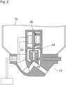
- the grit discharge device shown has a grit tank 10 which is funnel-shaped in its lower part and the bottom of which is formed at the lowest point by a discharge unit 12 which is flanged on detachably.
- a supply line 16 is formed in a housing block 14 of the discharge unit 12 and is 1 runs perpendicular to the plane of the drawing and is connected to a compressed air source 18 shown only schematically here.
- the supply line 16 is connected via a valve chamber 20 to a pressure line 22 through which the compressed air is injected coaxially via a nozzle 24 into a discharge line 26 for the spreading material.
- the downstream part of the pressure line 22, the nozzle 24 and the discharge channel 26 are arranged obliquely to the vertical in the example shown when the discharge unit 12 is mounted on the grit tank 10.
- the axis of the discharge line 26 forms an angle of slightly more than 45° with the vertical.
- the upper end of the discharge line 26, i.e. the end at which the nozzle 24 is located, is connected to a suction channel 28 which branches off at right angles to the discharge line 26 and thus rises towards the discharge line at an angle of slightly more than 45°.
- the lower end of the intake duct 28 is connected to the interior of the grit tank 10 via an elbow 30 formed in the housing block 14 .
- the discharge line 26 is extended outside of the housing block 14 by a line 32 designed as a hose or tube, which is thus also part of the discharge line.
- valve chamber 20 shown is part of a line system which runs vertically upwards from the supply line 16 along the axis of the housing block 14 and branches above the valve chamber 20 into the pressure line 22 and a first bypass channel 34 .
- the inlet of the bypass channel 34 is opposite the inlet of the pressure line 22 .
- Both inlets form valve seats for a valve member 36 of an electromagnetically actuated valve 38 which is accommodated in a part of the housing block 14 which is located inside the spreading material tank 10.
- the first bypass channel 34 leads to a valve chamber 40 of a manually adjustable control valve 42.
- a second bypass channel 44 leads directly from the supply line 16 to the valve chamber 40, and a third bypass channel 46 connects the valve chamber 40 to a point on the discharge line 26 downstream of the confluence point of the intake duct 28.
- the control valve 42 is designed as a needle valve, with which the cross section of the passage from the first bypass channel 44 to the valve chamber 40 can be continuously adjusted. The further the control valve 42 is open, the greater the proportion of the compressed air that flows directly to the discharge line 26 via the second bypass channel 44 and the third bypass channel 46 and does not cause any grit to be sucked in, but only serves to supply the discharge line 26, including those on it to keep the subsequent line 32 free of residues of grit or other contaminants.
- the actuator 36 of the valve 38 is pivotable about an axis 48 fixed with respect to the housing block 14 and protrudes with its lower part through the gap between the valve seats formed at the inlets of the pressure line 22 and the first bypass channel 34 into the valve chamber 20.
- the valve member 36 rests against the valve seat formed at the inlet of the first bypass passage 34, so that the first bypass passage is kept closed.
- all of the compressed air that cannot flow out via the second bypass channel 44 flows via the pressure line 22 and the nozzle 24 into the discharge line 26, where it causes the grit to be sucked in and discharged.
- the part of the valve member 36 lying above the axis 48 forms a magnet armature which lies in a coil 50 of an electromagnetic actuating unit and is elastically pushed into the in 1 shown position is biased.
- the coil 50 When the coil 50 is energized via electrical leads 54, it pulls the valve member 36 into the opposite end position, which is in 2 1 and in which the valve member abuts the valve seat formed by the inlet of the penstock 22.
- the spreading agent discharge is completely interrupted.
- connection socket 56 formed in this housing block, to which an electronic control device 58 for the valve 38 is connected.
- the connection socket 56 is located in an easily accessible position on that part of the housing block 14 which is located below the spreading agent tank 10 .
- the control device 58 supplies a square-wave pulse signal to the coil 50, so that the valve member 36 alternately moves between the in 1 and 2 positions shown.
- the switching frequency can be in the order of 3 to 20 Hz, for example and depends on the length of the discharge line 26 including the subsequent line 32.
- FIG 3 shows schematically a bogie 60 of a rail vehicle and front wheels 62 and rear wheels 64 on this bogie as well as a section of a rail 66 on which the wheels 62, 64 roll.
- the line 32 coming from the grit discharge device ends in a nozzle 68 directly in front of the contact points of the front wheels 62.
- the grit tank 10 and the discharge unit 12 are fixed to the bogie or alternatively to the vehicle body using a bracket (not shown). In the latter case, the line 32 should be flexible.
- FIG 4 shows schematically a longitudinal section through a section of the discharge line 26 or the line 32 adjoining it. Due to the intermittent operation of the valve 38, the grit is released in batches 70, with each batch being produced within an interval in which the valve is in the in 1 shown condition. The compressed air and the charges 70 of the spreading agent flow in 4 left to right. In the upstream area of the discharge line, the batches 70 are still clearly separated from one another. However, since the grit particles do not all have the same velocity, the charges 70 gradually disperse during transport through the discharge line, so that they continue to pull apart and coalesce towards the downstream end of the discharge line, as shown on the right in FIG 4 is shown. In this way, a steady stream of grit with a practically constant throughput of grit is achieved at the nozzle 68 . The greater the overall length of the discharge line 26 and the line 32, the smaller the switching frequency of the valve 38 can be selected.
- the time-averaged quantity of scattering agent released per unit of time is in any case determined by the pulse duty factor of the pulse signal with which the coil 50 is driven. By varying this pulse duty factor by means of the control device 58, the discharge quantity of spreading material can thus be adjusted as required and dosed precisely.
- valve 38 has a very simple structure and has only two possible switching positions, precise dosing can be achieved by pulse width modulation of the control signal, and by changing the modulation the amount of spreading material can also be adapted very quickly to the current requirement.
- all moving parts of the device in particular the valve member 36, are arranged in such a way that they are effectively protected against the ingress of grit and are therefore not subject to the abrasive effect of the grit.
- the duty cycle of the control signal can vary between 0 and 100%.
- the pressure line 22 is constantly open ( 1 ).
- the throughput of spreading material is then determined by the adjustment of the control valve 42 .
- a pulse duty factor of 100% no spreading material is discharged, even if the pressure source 18 is still active. In this state, the discharge line 26 and the line 32 can be effectively blown clear with the entire amount of compressed air available.
- the pulse duty factor will be varied as a function of the driving speed of the vehicle so that the same quantity of grit is applied for each meter driven.
- the duty cycle can also be additionally varied as a function of the operating voltage of the compressor in order to compensate for changes in the power of the compressor.
- valve 38 Since the valve 38 will have some inertia in practice, duty cycles close to 0% and duty cycles close to 100% may not be reproduced with the desired accuracy when the frequency of the control signal is fixed. It is therefore expedient to set a certain minimum duration for the useful pulses and also a certain minimum duration for the pulse gaps for the pulse width modulated control signal and, if this minimum duration is not reached, to adapt the duty cycle by reducing the frequency of the pulse width modulation signal.
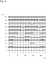
- An example of such a pulse width modulation scheme is in figure 5 shown. The time in milliseconds is plotted on the horizontal axis there, and various signal curves for duty cycles between 0 and 100% are shown.
- the pulse width modulation signal has a frequency of 10 Hz and accordingly a period of 100 ms.
- the useful pulses have a duration of 50 ms and the pulse gaps also have a duration of 50 ms.
- a duty cycle of 30% can be represented with an unchanged frequency by shortening the pulse duration to 30 ms.
- a duty cycle of 20% can be achieved by shortening the pulse duration to 20 ms. In the example shown, this value of 20 ms is the minimum pulse duration for the useful pulse.
- the useful pulse duration is left unchanged at 20 ms and the frequency is reduced instead, so that the period of the modulation signal increases to 133 ms.
- a pulse duty factor of 10% is obtained.
- the duration of the pulse gap is kept at the minimum value of 20 ms.
- a pulse duty factor of 85 or 90% can then be achieved by increasing the period duration to 133 ms or 200 ms.
- the coil remains 50 either completely de-energized (duty cycle 0%) or permanently energized (duty cycle 100%).
Landscapes
- Engineering & Computer Science (AREA)
- Mechanical Engineering (AREA)
- Transportation (AREA)
- Coating Apparatus (AREA)
- Nozzles (AREA)
Description
- Die Erfindung betrifft eine Streumittelaustragvorrichtung für Schienenfahrzeuge, mit einem Streumitteltank, einer Druckluftquelle, die über eine Druckleitung und eine Düse mit einer Austragleitung für das Streumittel verbunden ist, einem Ansaugkanal, über den das Streumittel aus dem Streumitteltank in die Austragleitung zuführbar ist, einem Bypass, der von der Druckleitung unter Umgehung der Düse zu einem Punkt in der Austragleitung stromabwärts der Mündung des Ansaugkanals führt und dessen Durchlassquerschnitt durch ein Ventil steuerbar ist, und mit einer elektronischen Steuereinrichtung für das Ventil.
- Vorrichtungen dieser Art dienen bei Schienenfahrzeugen dazu, Sand oder ein anderes Streumittel unmittelbar vor dem Aufstandspunkt eines Rades des Schienenfahrzeugs auf die Lauffläche des Schienenkopfes zu streuen, damit die Reibung zwischen Rad und Schiene erhöht wird, und so beim Anfahren eine höhere Traktion und beim Bremsen ein kürzerer Bremsweg erreicht wird. Die Ausbringung des Streumittels auf die Schiene sollte möglichst gleichmäßig folgen, damit stabile Anfahr- und Bremsbedingungen sichergestellt werden können.
- Ein Beispiel einer Streumittelaustragvorrichtung der oben genannten Art ist in
EP 2 311 653 B1 beschrieben. Durch die Düse wird die Druckluft mit erhöhter Geschwindigkeit in den Austragkanal ausgestoßen, so dass das Streumittel nach dem Strahlpumpenprinzip über die Ansaugleitung angesaugt und dann zusammen mit der Druckluft durch die Austragleitung transportiert werden kann. Wenn das Ventil im Bypass geöffnet wird, so nimmt der Volumenstrom und die Strömungsgeschwindigkeit der durch die Düse strömenden Druckluft ab, so dass entsprechend weniger Streumittel angesaugt wird. Durch geeignete Einstellung des Öffnungsquerschnitts des Ventils lässt sich so die ausgebrachte Streumittelmenge dosieren. Bei der bekannten Vorrichtung hat der Bypass im Verhältnis zum Düsenquerschnitt einen relativ großen Querschnitt, so dass bei ganz geöffnetem Ventil der Volumenstrom durch die Düse nahezu vollständig zum Erliegen kommt. Durch die Druckluft, die dann über den Bypass in die Austragleitung strömt, kann die Austragleitung freigeblasen werden. Auf diese Weise kann Verstopfungen der Austragleitung vorgebeugt werden, indem in gewissen Abständen auf die Betriebsart mit vollständig geöffnetem Ventil umgeschaltet wird. - Aus
DE 20 2014 102 881 U1 ist eine Streumittelaustragvorrichtung bekannt, bei der zur Dosierung des Streumittels ein pulsweitenmoduliertes Magnetventil vorgesehen ist. - Aufgabe der Erfindung ist es, eine Streumittelaustragsvorrichtung zu schaffen, die eine einfachere und genauere Dosierung des Streumittels erlaubt.
- Diese Aufgabe wird erfindungsgemäß dadurch gelöst, dass die Steuereinrichtung dazu ausgebildet ist, das Ventil intervallweise zu öffnen und zu schließen, mit einer Frequenz, die so auf die Länge der Austragleitung abgestimmt ist, dass sich die in den einzelnen Öffnungsperioden des Ventils ausgestoßenen Chargen des Streumittels in der Austragleitung zu einem stetigen Streumittelstrom vereinigen.
- Bei der erfindungsgemäßen Vorrichtung ist die im zeitlichen Mittel aufgebrachte Streumittelmenge durch das Verhältnis zwischen der Dauer der Schließperioden und der Dauer der Öffnungsperioden des Ventils bestimmt. Je kürzer die Schließperioden des Ventils sind, desto kürzer sind die Intervalle, in denen die Druckluft mit hohem Volumenstrom und hoher Geschwindigkeit durch die Düse strömt und in denen das Streumittel wirksam angesaugt wird. Zum Dosieren der Streumittelmenge wird somit kein Proportionalventil benötigt, sondern es kann ein einfach aufgebautes Ventil verwendet werden, das nur zwischen einer vollständig geöffneten Stellung und einer vollständig geschlossenen Stellung umschaltbar ist. Die Ansteuerung dieses Ventils kann beispielsweise mittels eines von der Steuereinrichtung erzeugten Impulssignals erfolgen, dessen Tastverhältnis dann die mittlere Streumittelmenge bestimmt.
- Da jedoch bei dieser Vorrichtung die Düse nur intervallweise aktiv ist, wird das Streumittel nicht gleichmäßig angesaugt, sondern in getrennten, zeitlich aufeinanderfolgenden Chargen, die den Schließperioden des Ventils entsprechen. Bei hinreichend hoher Frequenz des Steuersignals folgen jedoch die einzelnen Chargen in so kurzen Abständen aufeinander, dass es auf dem Weg des Streumittels durch die Austragleitung aufgrund von Geschwindigkeitsunterschieden zwischen den einzelnen Streumittelpartikeln zu einer Dispersion der Chargen kommt, so dass diese sich zum Auslass der Austragleitung hin zu einem stetigen Streumittelstrom vereinigen und somit das Streumittel trotz des Intervallbetriebs des Ventils im wesentlichen gleichmäßig ausgebracht werden kann.
- Vorteilhafte Ausgestaltungen und Weiterbildungen der Erfindung sind in den Unteransprüchen angegeben.
- Das Ventil, das beispielsweise elektromagnetisch betätigt werden kann, ist in einer vorteilhaften Ausführungsform als Klappventil mit zwei Stellungen ausgebildet, das in einer Stellung den Zugang zum Bypass versperrt und den Strömungsweg zur Düse offen hält und in der anderen Stellung den Zugang zum Bypass offen hält und den Strömungsweg zur Düse versperrt. In der Stellung, in der der Strömungsweg zur Düse versperrt ist, wird dann keinerlei Streumittel angesaugt, so dass dieser Betriebszustand auch zum Freiblasen der Austragleitung genutzt werden kann.
- In einer vorteilhaften Ausführungsform weist der Bypass zwei parallele Kanäle auf, von denen nur einer durch das intervallweise betätigte Ventil gesteuert wird. Der andere Kanal kann ständig offen bleiben oder mittels eines manuell einstellbaren oder elektronisch betätigten aber relativ langsam ansprechenden Ventils gedrosselt werden, so dass über diesen Bypasskanal ständig eine gewisse Luftmenge in den Austragkanal zugeführt wird, damit einem Verstopfen des Austragkanals vorgebeugt wird. Zugleich kann durch das Zusammenwirken des intervallweise betätigten Ventils mit dem fest eingestellten oder langsam ansprechenden Ventil eine größere Variationsbreite bei der Grundeinstellung des maximalen Streumitteldurchsatzes erreicht werden.
- Die Druckleitung, die Düse, der Bypass und zumindest ein stromaufwärtiger Teil der Austragleitung können zweckmäßig in eine Austrageinheit integriert sein, die sich so an den Streumitteltank anbauen lässt, dass sie einen Teil des Bodens des Streumitteltanks bildet. Dabei können das Ventil und die zugehörige Betätigungseinheit ebenfalls in die Austrageinheit integriert und beispielsweise so angeordnet sein, dass sie sich im Inneren des Streumitteltanks befinden. Die Zufuhr des Steuersignals zu dem Ventil erfolgt dann vorzugsweise über einen Anschluss, der sich in dem von außen zugänglichen Teil der Austrageinheit befindet.
- Im folgenden wird ein Ausführungsbeispiel anhand der Zeichnung näher erläutert. Es zeigen:
- Fig. 1
- einen schematischen Schnitt durch eine erfindungsgemäße Streumittelaustragvorrichtung;
- Fig. 2
- die wesentlichen Teile der Vorrichtung nach
Fig. 1 in einem anderen Betriebszustand; - Fig. 3
- eine Prinzipskizze der Streumittelaustragvorrichtung an einem Radsatz eines Schienenfahrzeugs;
- Fig. 4
- einen schematischen Längsschnitt durch einen Abschnitt einer Austragleitung, durch welche das Streumittel transportiert wird; und
- Fig. 5
- ein Zeitdiagramm zur Illustration unterschiedlicher Steuersignalverläufe.
- Die in
Fig. 1 gezeigte Streumittelaustragvorrichtung weist einen Streumitteltank 10 auf, der in seinem unteren Teil trichterförmig ausgebildet ist und dessen Boden an der tiefsten Stelle durch eine lösbar angeflanschte Austrageinheit 12 gebildet wird. In einem Gehäuseblock 14 der Austrageinheit 12 ist eine Zufuhrleitung 16 ausgebildet, die inFig. 1 senkrecht zur Zeichenebene verläuft und an eine hier nur schematisch gezeigte Druckluftquelle 18 angeschlossen ist. Die Zufuhrleitung 16 ist über eine Ventilkammer 20 mit einer Druckleitung 22 verbunden, durch welche die Druckluft über eine Düse 24 koaxial in eine Austragleitung 26 für das Streumittel eingedüst wird. Der stromabwärtige Teil der Druckleitung 22, die Düse 24 und der Austragkanal 26 sind im gezeigten Beispiel schräg zur Vertikalen angeordnet, wenn die Austrageinheit 12 am Streumitteltank 10 montiert ist. Beispielsweise bildet die Achse der Austragleitung 26 mit der Vertikalen einen Winkel von etwas mehr als 45°. Das obere Ende der Austragleitung 26, also das Ende, an dem sich die Düse 24 befindet, ist mit einem Ansaugkanal 28 verbunden, der rechtwinklig von der Austragleitung 26 abgeht und somit zu der Austragleitung hin unter einem Winkel von etwas mehr als 45° ansteigt. Das untere Ende des Ansaugkanals 28 ist über einen in dem Gehäuseblock 14 gebildeten Krümmer 30 mit dem Inneren des Streumitteltanks 10 verbunden. - Das Streumittel aus dem Streumitteltank 10 rieselt somit durch Schwerkraftwirkung in den Krümmer 30. Der Höhenunterschied zwischen der tiefsten Stelle des Krümmers und dem oberen Ende des Ansaugkanals 28 ist jedoch so groß, dass das Streumittel nicht allein durch Schwerkraftwirkung in die Austragleitung 26 überläuft. Erst wenn über die Düse 24 Druckluft in die Austragleitung 26 eingestrahlt wird, entsteht im oberen Ende der Austragleitung 26, die hier einfach durch eine zylindrische Bohrung im Gehäuseblock 14 gebildet wird, ein Unterdruck, so dass das Streumittel nach dem Strahlpumpenprinzip angesaugt und dann zusammen mit der Druckluft durch die Austragleitung 26 zu deren auslassseitigem Ende transportiert wird.
- Wie in
Fig. 3 gezeigt ist, wird die Austragleitung 26 außerhalb des Gehäuseblockes 14 durch eine als Schlauch oder Rohr ausgebildete Leitung 32 verlängert, die somit ebenfalls Teil der Austragleitung ist. - Die in
Fig. 1 gezeigte Ventilkammer 20 ist Teil eines Leitungssystems, das von der Zufuhrleitung 16 vertikal längs der Achse des Gehäuseblocks 14 nach oben verläuft und sich oberhalb der Ventilkammer 20 in die Druckleitung 22 und einen ersten Bypasskanal 34 verzweigt. Der Einlass des Bypasskanals 34 liegt dem Einlass der Druckleitung 22 gegenüber. Beide Einlässe bilden Ventilsitze für ein Ventilglied 36 eines elektromagnetisch betätigten Ventils 38, das in einem Teil des Gehäuseblocks 14 aufgenommen ist, der sich im Inneren des Streumitteltanks 10 befindet. - Der erste Bypasskanal 34 führt zu einer Ventilkammer 40 eines von Hand einstellbaren Stellventils 42. Ein zweiter Bypasskanal 44 führt unmittelbar von der Zufuhrleitung 16 zu der Ventilkammer 40, und ein dritter Bypasskanal 46 verbindet die Ventilkammer 40 mit einem Punkt der Austragleitung 26 stromabwärts der Einmündungsstelle des Ansaugkanals 28.
- Das Stellventil 42 ist als Nadelventil ausgebildet, mit dem sich der Querschnitt des Durchlasses vom ersten Bypasskanal 44 zur Ventilkammer 40 stufenlos einstellen lässt. Je weiter das Stellventil 42 geöffnet ist, desto größer ist der Anteil der Druckluft, der über den zweiten Bypasskanal 44 und den dritten Bypasskanal 46 unmittelbar zur Austragleitung 26 strömt und keine Ansaugung von Streumittel bewirkt, sondern lediglich dazu dient, die Austragleitung 26 einschließlich der daran anschließenden Leitung 32 von Streumittelresten oder sonstigen Verunreinigungen frei zu halten.
- Das Stellglied 36 des Ventils 38 ist um eine in Bezug auf den Gehäuseblock 14 feste Achse 48 schwenkbar und ragt mit seinem unteren Teil durch den Zwischenraum zwischen den an den Einlässen der Druckleitung 22 und des ersten Bypasskanals 34 gebildeten Ventilsitzen in die Ventilkammer 20. In dem in
Fig. 1 gezeigten Zustand liegt das Ventilglied 36 an dem Ventilsitz an, der am Einlass des ersten Bypasskanals 34 gebildet ist, so dass der erste Bypasskanal geschlossen gehalten wird. In diesem Zustand strömt somit die gesamte Druckluft, die nicht über den zweiten Bypasskanal 44 abfließen kann, über die Druckleitung 22 und die Düse 24 in die Austragleitung 26, wo sie das Ansaugen und Austragen von Streumittel bewirkt. - Der oberhalb der Achse 48 liegende Teil des Ventilglieds 36 bildet einen Magnetanker, der in einer Spule 50 einer elektromagnetischen Betätigungseinheit liegt und durch eine Feder 52 elastisch in die in
Fig. 1 gezeigte Stellung vorgespannt ist. Wenn die Spule 50 über elektrische Zuleitungen 54 bestromt wird, zieht sie das Ventilglied 36 in die entgegengesetzte Endlage, die inFig. 2 gezeigt ist und in der das Ventilglied an dem Ventilsitz anliegt, der durch den Einlass der Druckleitung 22 gebildet wird. In diesem Zustand ist somit der Zugang zur Druckleitung 22 gesperrt, so dass die gesamte Druckluft über die Bypasskanäle 34 und 44 und dann weiter über den dritten Bypasskanal 46 abströmt. In diesem Zustand ist somit der Streumittelaustrag vollständig unterbrochen. - Die elektrischen Zuleitungen 54 führen innerhalb des Gehäuseblockes 14 zu einer in diesem Gehäuseblock gebildeten Anschlussbuchse 56, an die eine elektronische Steuereinrichtung 58 für das Ventil 38 angeschlossen ist. Die Anschlussbuchse 56 befindet sich in einer gut zugänglichen Position an dem Teil des Gehäuseblockes 14, der sich unterhalb des Streumitteltanks 10 befindet.
- Wenn die Streumittelaustragvorrichtung in Betrieb ist, liefert die Steuereinrichtung 58 ein rechteckförmiges Impulssignal an die Spule 50, so dass das Ventilglied 36 abwechselnd zwischen den in
Fig. 1 und2 gezeigten Stellungen umgeschaltet wird. Die Umschaltfrequenz kann dabei beispielsweise in der Größenordnung von 3 bis 20 Hz liegen und richtet sich nach der Länge der Austragleitung 26 einschließlich der anschließenden Leitung 32. - In
Fig. 3 sind schematisch ein Drehgestell 60 eines Schienenfahrzeugs und vordere Räder 62 und hintere Räder 64 an diesem Drehgestell sowie ein Abschnitt einer Schiene 66 gezeigt, auf der die Räder 62, 64 abrollen. Die von der Streumittelaustragvorrichtung kommende Leitung 32 endet in einer Düse 68 unmittelbar vor den Aufstandspunkten der vorderen Räder 62. Der Streumitteltank 10 und die Austrageinheit 12 sind mit Hilfe einer nicht gezeigten Halterung fest am Drehgestell oder wahlweise auch am Fahrzeugaufbau montiert. Im letzteren Fall sollte die Leitung 32 flexibel sein. -
Fig. 4 zeigt schematisch einen Längsschnitt durch einen Abschnitt der Austragleitung 26 oder der daran anschließenden Leitung 32. Aufgrund des Intervallbetriebs des Ventils 38 wird das Streumittel in Chargen 70 abgegeben, wobei jede Charge innerhalb eines Intervalls erzeugt wird, in dem sich das Ventil in dem inFig. 1 gezeigten Zustand befindet. Die Druckluft und die Chargen 70 des Streumittels strömen inFig. 4 von links nach rechts. Im stromaufwärtigen Bereich der Austragleitung sind die Chargen 70 noch deutlich voneinander getrennt. Da jedoch die Streumittelpartikel nicht alle die gleiche Geschwindigkeit haben, kommt es während des Transports durch die Austragleitung zu einer allmählichen Dispersion der Chargen 70, so dass diese sich immer weiter auseinanderziehen und sich zum stromabwärtigen Ende der Austragleitung hin vereinigen, wie rechts inFig. 4 dargestellt ist. Auf diese Weise wird an der Düse 68 ein stetiger Streumittelstrom mit praktisch konstantem Streumitteldurchsatz erreicht. Je größer die Gesamtlänge der Austragleitung 26 und der Leitung 32 ist, desto kleiner kann die Umschaltfrequenz des Ventils 38 gewählt werden. - Die im zeitlichen Mittel je Zeiteinheit abgegebene Menge an Streumittel ist in jedem Fall durch das Tastverhältnis des Impulssignals bestimmt, mit dem die Spule 50 angesteuert wird. Indem mittels der Steuereinrichtung 58 dieses Tastverhältnis variiert wird, lässt sich somit die Austragmenge an Streumittel nach Bedarf einstellen und präzise dosieren.
- Obgleich das Ventil 38 einen sehr einfachen Aufbau hat und nur zwei mögliche Schaltstellungen aufweist, lässt sich durch Pulsweitenmodulation des Steuersignals eine präzise Dosierung erreichen, und durch Änderung der Modulation kann zudem die Streumittelmenge sehr rasch an den aktuellen Bedarf angepasst werden.
- Bei dem in
Fig. 1 gezeigten Aufbau sind alle beweglichen Teile der Vorrichtung, insbesondere das Ventilglied 36, so angeordnet, dass sie wirksam gegen das Eindringen von Streumittel geschützt sind und somit nicht der abrasiven Wirkung des Streumittels unterliegen. - Das Tastverhältnis des Steuersignals kann im Prinzip zwischen 0 und 100% variieren. Bei einem Tastverhältnis von 0% ist die Druckleitung 22 ständig geöffnet (
Fig. 1 ). Der Durchsatz an Streumittel wird dann durch die Einstellung des Stellventils 42 bestimmt. Bei einem Tastverhältnis von 100% findet kein Streumittelaustrag statt, auch dann nicht, wenn die Druckquelle 18 weiterhin aktiv ist. In diesem Zustand kann ein wirksames Freiblasen der Austragleitung 26 und der Leitung 32 mit der gesamten zur Verfügung stehenden Druckluftmenge erreicht werden. - Im allgemeinen wird das Tastverhältnis so in Abhängigkeit von der Fahrgeschwindigkeit des Fahrzeugs variiert werden, dass je gefahrenem Meter die gleiche Menge an Streumittel ausgebracht wird. Wenn jedoch der als Druckquelle 18 dienende Kompressor aus einer Spannungsquelle gespeist wird, deren Spannung signifikanten Schwankungen unterliegt, so kann das Tastverhältnis auch zusätzlich in Abhängigkeit von der Betriebsspannung des Kompressors variiert werden, um Leistungsänderungen des Kompressors auszugleichen.
- Da das Ventil 38 in der Praxis eine gewisse Trägheit aufweisen wird, können bei fester Frequenz des Steuersignals Tastverhältnisse in der Nähe von 0 % sowie Tastverhältnisse in der Nähe von 100 % unter Umständen nicht mit der gewünschten Genauigkeit reproduziert werden. Es ist deshalb zweckmäßig, für das pulsweitenmodulierte Steuersignal eine gewisse Mindestdauer der Nutzimpulse und ebenso eine gewisse Mindestdauer der Impulslücken festzulegen und, wenn diese Mindestdauer unterschritten wird, das Tastverhältnis durch Verringerung der Frequenz des Pulsweitenmodulationssignals anzupassen. Ein Beispiel für ein solches Schema zur Pulsweitenmodulation ist in
Fig. 5 gezeigt. Auf der horizontalen Achse ist dort die Zeit in Millisekunden aufgetragen, und es sind verschiedene Signalverläufe für Tastverhältnisse zwischen 0 und 100 % dargestellt. Bei einem Tastverhältnis in der Nähe von 50 % hat das Pulsweitenmodulationssignal eine Frequenz von 10 Hz und dementsprechend eine Periodendauer von 100 ms. Bei einem Tastverhältnis von genau 50 % haben somit die Nutzimpulse eine Dauer von 50 ms und die Impulslücken ebenfalls eine Dauer von 50 ms. Ein Tastverhältnis von 30 % lässt sich bei unveränderter Frequenz dadurch darstellen, dass die Impulsdauer auf 30 ms verkürzt wird. Entsprechend kann durch eine Verkürzung der Pulsdauer auf 20 ms ein Tastverhältnis von 20 % dargestellt werden. Im gezeigten Beispiel ist dieser Wert von 20 ms die Mindestimpulsdauer für den Nutzimpuls. Um ein Tastverhältnis von 15 % zu realisieren, lässt man deshalb die Nutzimpulsdauer unverändert bei 20 ms, und man verringert statt dessen die Frequenz, so dass die Periodendauer des Modulationssignals auf 133 ms zunimmt. Entsprechend erhält man bei einer Modulationsperiode von 200 ms und einer Nutzimpulsdauer von 20 ms ein Tastverhältnis von 10 %. - Bei Tastverhältnissen von über 80 % hält man die Dauer der Impulslücke auf dem Minimalwert von 20 ms. Ein Tastverhältnis von 85 oder 90 % lässt sich dann durch Vergrößerung der Periodendauer auf 133 ms bzw. 200 ms realisieren.
- Weiterhin ist es zweckmäßig, für die Frequenz des Pulsweitenmodulationssignals eine Untergrenze festzulegen. Bei Unterschreiten dieser Untergrenze bleibt die Spule 50 entweder vollständig unbestromt (Tastverhältnis 0 %) oder ständig bestromt (Tastverhältnis 100 %).
Claims (11)
- Streumittelaustragvorrichtung für Schienenfahrzeuge, mit einem Streumitteltank (10), einer Druckluftquelle (18) die über eine Druckleitung (22) und eine Düse (24) mit einer Austragleitung (26) für das Streumittel verbunden ist, einem Ansaugkanal (28), über den das Streumittel aus dem Streumitteltank (10) in die Austragleitung (26) zuführbar ist, einem Bypass (34, 44, 46), der von der Druckleitung (22) unter Umgehung der Düse (24) zu einem Punkt in der Austragleitung (26) stromabwärts der Mündung des Ansaugkanals (28) führt und dessen Durchlassquerschnitt durch ein Ventil (38) steuerbar ist, und mit einer elektronischen Steuereinrichtung (58) für das Ventil (38), dadurch gekennzeichnet, dass die Steuereinrichtung (58) dazu ausgebildet ist, das Ventil (38) intervallweise zu öffnen und zu schließen, mit einer Frequenz, die so auf die Länge der Austragleitung (26; 32) abgestimmt ist, dass sich die in den einzelnen Öffnungsperioden des Ventils ausgestoßenen Chargen (70) des Streumittels in der Austragleitung zu einem stetigen Streumittelstrom vereinigen.
- Vorrichtung nach Anspruch 1, bei der das Ventil (38) ein magnetisch betätigtes Ventil mit zwei Schaltstellungen ist.
- Vorrichtung nach Anspruch 2, bei der das Ventil (38) ein Klappventil ist, das in einer Schaltstellung die Druckleitung (22) offen hält und einen Bypasskanal (34) sperrt und in der anderen Schaltstellung die Druckleitung (22) sperrt und den Bypasskanal (34) offen hält.
- Vorrichtung nach einem der vorstehenden Ansprüche, bei der der Bypass (34, 44, 46) zwei parallele Bypasskanäle (34, 44) aufweist, von denen nur einer durch das intervallweise gesteuerte Ventil (38) zu öffnen und zu schließen ist.
- Vorrichtung nach Anspruch 4, bei der mindestens einer der Bypasskanäle (34, 44) durch ein weiteres Ventil (42) unabhängig vom Zustand des intervallweise gesteuerten Ventils (38) in seinem Öffnungsquerschnitt veränderbar ist.
- Vorrichtung nach Anspruch 4 oder 5, bei der die beiden Bypasskanäle (34, 44) über einen gemeinsamen dritten Bypasskanal (46) mit der Austragleitung (26) verbunden sind.
- Vorrichtung nach einem der vorstehenden Ansprüche, bei der die Druckleitung (22), die Düse (24), zumindest ein Teil der Austragleitung (26) und der Ansaugkanal (28) in einem Gehäuseblock (14) gebildet sind, der einen Teil des Bodens des Streumitteltanks (10) bildet, und bei der das Ventil (38) im Inneren des Streumitteltanks (10) an dem Gehäuseblock (14) angeordnet ist.
- Vorrichtung nach Anspruch 7, bei der elektrische Zuleitungen (54) für das Ventil (38) innerhalb des Gehäuseblockes (14) zu einer Anschlussbuchse (56) geführt sind, die sich in einer zugänglichen Position außerhalb des Streumitteltanks (10) befindet und an die die Steuereinrichtung (58) anschließbar ist.
- Vorrichtung nach einem der vorstehenden Ansprüche, bei der die Steuereinrichtung (58) dazu ausgebildet ist, das Tastverhältnis, mit dem das Ventil (38) geöffnet und geschlossen wird, situationsabhängig zu variieren.
- Vorrichtung nach Anspruch 9, bei der die Steuereinrichtung (58) dazu ausgebildet ist, das Tastverhältnis in Abhängigkeit von der Fahrgeschwindigkeit des Schienenfahrzeugs und in Abhängigkeit von der Leistung der Druckluftquelle (18) zu variieren.
- Vorrichtung nach Anspruch 9 oder 10, bei der die Steuereinrichtung (58) dazu ausgebildet ist, das Ventil (38) mit einem Pulsweitenmodulationssignal mit variabler Frequenz anzusteuern, wobei sowohl die Dauer der Nutzimpulse des Pulsweitenmodulationssignals als auch die Dauer der Lücken zwischen diesen Nutzimpulsen eine bestimmte Mindestdauer nicht unterschreiten und Tastverhältnisse in der Nähe von 0% sowie Tastverhältnisse in der Nähe von 100 % dadurch realisiert werden, dass bei fester Dauer der Nutzimpulse bzw. der Impulslücken die Frequenz des Pulsweitenmodulationssignals innerhalb eines vorgegebenen Variationsbereiches verringert wird.
Priority Applications (1)
| Application Number | Priority Date | Filing Date | Title |
|---|---|---|---|
| PL18825657T PL3727874T3 (pl) | 2017-12-20 | 2018-12-17 | Urządzenie podające materiał sypany, przeznaczone dla pojazdów szynowych |
Applications Claiming Priority (2)
| Application Number | Priority Date | Filing Date | Title |
|---|---|---|---|
| DE202017107772.1U DE202017107772U1 (de) | 2017-12-20 | 2017-12-20 | Streumittelaustragvorrichtung für Schienenfahrzeuge |
| PCT/EP2018/085304 WO2019121563A1 (de) | 2017-12-20 | 2018-12-17 | Streumittelaustragvorrichtung für schienenfahrzeuge |
Publications (2)
| Publication Number | Publication Date |
|---|---|
| EP3727874A1 EP3727874A1 (de) | 2020-10-28 |
| EP3727874B1 true EP3727874B1 (de) | 2022-02-16 |
Family
ID=64755557
Family Applications (1)
| Application Number | Title | Priority Date | Filing Date |
|---|---|---|---|
| EP18825657.2A Active EP3727874B1 (de) | 2017-12-20 | 2018-12-17 | Streumittelaustragvorrichtung für schienenfahrzeuge |
Country Status (7)
| Country | Link |
|---|---|
| US (1) | US11267284B2 (de) |
| EP (1) | EP3727874B1 (de) |
| CA (1) | CA3075593C (de) |
| DE (1) | DE202017107772U1 (de) |
| ES (1) | ES2909244T3 (de) |
| PL (1) | PL3727874T3 (de) |
| WO (1) | WO2019121563A1 (de) |
Families Citing this family (2)
| Publication number | Priority date | Publication date | Assignee | Title |
|---|---|---|---|---|
| DE202017107772U1 (de) * | 2017-12-20 | 2019-03-25 | Hanning & Kahl Gmbh & Co. Kg | Streumittelaustragvorrichtung für Schienenfahrzeuge |
| CN111216744B (zh) * | 2019-12-27 | 2021-03-16 | 湖南联诚轨道装备有限公司 | 一种用于机车的撒砂装置 |
Citations (2)
| Publication number | Priority date | Publication date | Assignee | Title |
|---|---|---|---|---|
| EP2311653B1 (de) * | 2009-10-16 | 2013-03-13 | MBM Holding GmbH | Sandaustragungseinrichtung für ein Schienenfahrzeug |
| DE202017107772U1 (de) * | 2017-12-20 | 2019-03-25 | Hanning & Kahl Gmbh & Co. Kg | Streumittelaustragvorrichtung für Schienenfahrzeuge |
Family Cites Families (8)
| Publication number | Priority date | Publication date | Assignee | Title |
|---|---|---|---|---|
| DE2938583A1 (de) * | 1979-09-24 | 1981-04-09 | Knorr-Bremse GmbH, 8000 München | Einrichtung zur verbesserung der beiwerte der haft- und gleitreibung von fahrzeugen, insbesondere strassenfahrzeugen |
| DE102004014360B4 (de) | 2004-03-24 | 2010-05-20 | Knorr-Bremse Systeme für Schienenfahrzeuge GmbH | Sandungseinrichtung für Schienenfahrzeuge |
| AT503940B1 (de) | 2006-11-29 | 2008-02-15 | Goldmann Norbert | Streugerät für ein fahrzeug, insbesondere ein schienenfahrzeug |
| AT507381B1 (de) * | 2008-09-22 | 2010-07-15 | Nowe Gmbh | Sanddosier- und absperreinrichtung |
| CN103068662B (zh) * | 2010-08-09 | 2016-11-09 | 通用电气公司 | 牵引力系统和方法 |
| US8738202B2 (en) * | 2010-11-18 | 2014-05-27 | Ztr Control Systems | Method and apparatus for controlling sanding on locomotives |
| US9056525B2 (en) * | 2013-01-02 | 2015-06-16 | The Boeing Company | Anti-skid systems for vehicle tires on icy road conditions and method therefor |
| DE202014102881U1 (de) * | 2014-06-24 | 2014-07-03 | Mbm Holding Gmbh | Schaltungsanordnung zur Ansteuerung von Sandungseinrichtungen |
-
2017
- 2017-12-20 DE DE202017107772.1U patent/DE202017107772U1/de not_active Expired - Lifetime
-
2018
- 2018-12-17 WO PCT/EP2018/085304 patent/WO2019121563A1/de not_active Ceased
- 2018-12-17 EP EP18825657.2A patent/EP3727874B1/de active Active
- 2018-12-17 PL PL18825657T patent/PL3727874T3/pl unknown
- 2018-12-17 ES ES18825657T patent/ES2909244T3/es active Active
- 2018-12-17 CA CA3075593A patent/CA3075593C/en active Active
- 2018-12-17 US US16/648,504 patent/US11267284B2/en active Active
Patent Citations (2)
| Publication number | Priority date | Publication date | Assignee | Title |
|---|---|---|---|---|
| EP2311653B1 (de) * | 2009-10-16 | 2013-03-13 | MBM Holding GmbH | Sandaustragungseinrichtung für ein Schienenfahrzeug |
| DE202017107772U1 (de) * | 2017-12-20 | 2019-03-25 | Hanning & Kahl Gmbh & Co. Kg | Streumittelaustragvorrichtung für Schienenfahrzeuge |
Also Published As
| Publication number | Publication date |
|---|---|
| CA3075593C (en) | 2022-03-15 |
| WO2019121563A1 (de) | 2019-06-27 |
| DE202017107772U1 (de) | 2019-03-25 |
| PL3727874T3 (pl) | 2022-06-13 |
| US11267284B2 (en) | 2022-03-08 |
| US20200215853A1 (en) | 2020-07-09 |
| ES2909244T3 (es) | 2022-05-06 |
| CA3075593A1 (en) | 2019-06-27 |
| EP3727874A1 (de) | 2020-10-28 |
Similar Documents
| Publication | Publication Date | Title |
|---|---|---|
| AT507381B1 (de) | Sanddosier- und absperreinrichtung | |
| EP0016471B1 (de) | Dosiereinrichtung für eine Sandungsanlage eines Fahrzeuges | |
| EP3727874B1 (de) | Streumittelaustragvorrichtung für schienenfahrzeuge | |
| DE4002760C2 (de) | ||
| DE102010055019A1 (de) | Vorrichtung zum intermittierenden Auftragen eines flüssigen bis pastösen Mediums auf eine Auftragfläche | |
| DE4429370A1 (de) | Vorrichtung für ein Kraftfahrzeug zur bedarfsweisen Ausbringung von Streugut | |
| DE102004014360B4 (de) | Sandungseinrichtung für Schienenfahrzeuge | |
| DE10252466A1 (de) | Druckluftbetriebene Sandstreuvorrichtung und Verfahren zum Streuen von Sand | |
| EP2311653B1 (de) | Sandaustragungseinrichtung für ein Schienenfahrzeug | |
| DE2632794B1 (de) | Salzstreugeraet mit streugutbefeuchtungseinrichtung fuer ein fahrzeug | |
| DE4127016A1 (de) | Sandstreuer fuer eine lokomotive | |
| WO2008003359A1 (de) | Pumpelement und pumpe mit einem solchen pumpelement | |
| DE3420972A1 (de) | Anordnung zum abziehen von gut bei einer filteranlage | |
| WO2025021527A1 (de) | Verfahren zum betreiben eines pneumatischen systems eines fahrzeugs, pneumatisches system, fahrzeug und druckluftversorgungsanlage und pneumatikanlage für ein pneumatisches system mit erwärmen zumindest eines der pneumatischen magnetventile | |
| WO2011009671A1 (de) | Dosierungsvorrichtung mit schaltventil und dämpfungsvolumen | |
| EP1854910B1 (de) | Steilarmvliesleger | |
| AT411897B (de) | Dosiereinrichtung für ein sandstreugerät, insbesondere für ein schienenfahrzeug | |
| DE3048876A1 (de) | Verfahren zur aenderung der richtung einer fluidstroemung durch eine duese sowie diesbezuegliche fluidauslassvorrichtung | |
| EP1312488A2 (de) | Streuanlage für ein Streugut | |
| DE60106616T2 (de) | Dosierpumpe zur abgabe eines zusatzstoffes in eine fluidströmung | |
| DE102023200069A1 (de) | Modulares Partikelaustragungssystem | |
| DE10115636A1 (de) | Umschaltventil in einem Fahrzeug | |
| DE3818760C2 (de) | ||
| DE2307351A1 (de) | Verfahren und einrichtung zur steuerung des stromes einer konstantpumpe | |
| DE20217390U1 (de) | Druckluftbetriebene Sandstreuvorrichtung |
Legal Events
| Date | Code | Title | Description |
|---|---|---|---|
| STAA | Information on the status of an ep patent application or granted ep patent |
Free format text: STATUS: UNKNOWN |
|
| STAA | Information on the status of an ep patent application or granted ep patent |
Free format text: STATUS: THE INTERNATIONAL PUBLICATION HAS BEEN MADE |
|
| PUAI | Public reference made under article 153(3) epc to a published international application that has entered the european phase |
Free format text: ORIGINAL CODE: 0009012 |
|
| STAA | Information on the status of an ep patent application or granted ep patent |
Free format text: STATUS: REQUEST FOR EXAMINATION WAS MADE |
|
| 17P | Request for examination filed |
Effective date: 20200304 |
|
| AK | Designated contracting states |
Kind code of ref document: A1 Designated state(s): AL AT BE BG CH CY CZ DE DK EE ES FI FR GB GR HR HU IE IS IT LI LT LU LV MC MK MT NL NO PL PT RO RS SE SI SK SM TR |
|
| AX | Request for extension of the european patent |
Extension state: BA ME |
|
| DAV | Request for validation of the european patent (deleted) | ||
| DAX | Request for extension of the european patent (deleted) | ||
| GRAP | Despatch of communication of intention to grant a patent |
Free format text: ORIGINAL CODE: EPIDOSNIGR1 |
|
| STAA | Information on the status of an ep patent application or granted ep patent |
Free format text: STATUS: GRANT OF PATENT IS INTENDED |
|
| INTG | Intention to grant announced |
Effective date: 20210917 |
|
| GRAS | Grant fee paid |
Free format text: ORIGINAL CODE: EPIDOSNIGR3 |
|
| GRAA | (expected) grant |
Free format text: ORIGINAL CODE: 0009210 |
|
| STAA | Information on the status of an ep patent application or granted ep patent |
Free format text: STATUS: THE PATENT HAS BEEN GRANTED |
|
| AK | Designated contracting states |
Kind code of ref document: B1 Designated state(s): AL AT BE BG CH CY CZ DE DK EE ES FI FR GB GR HR HU IE IS IT LI LT LU LV MC MK MT NL NO PL PT RO RS SE SI SK SM TR |
|
| REG | Reference to a national code |
Ref country code: GB Ref legal event code: FG4D Free format text: NOT ENGLISH |
|
| REG | Reference to a national code |
Ref country code: CH Ref legal event code: EP |
|
| REG | Reference to a national code |
Ref country code: DE Ref legal event code: R096 Ref document number: 502018008810 Country of ref document: DE |
|
| REG | Reference to a national code |
Ref country code: AT Ref legal event code: REF Ref document number: 1468668 Country of ref document: AT Kind code of ref document: T Effective date: 20220315 |
|
| REG | Reference to a national code |
Ref country code: IE Ref legal event code: FG4D Free format text: LANGUAGE OF EP DOCUMENT: GERMAN |
|
| REG | Reference to a national code |
Ref country code: ES Ref legal event code: FG2A Ref document number: 2909244 Country of ref document: ES Kind code of ref document: T3 Effective date: 20220506 |
|
| REG | Reference to a national code |
Ref country code: LT Ref legal event code: MG9D |
|
| REG | Reference to a national code |
Ref country code: NL Ref legal event code: MP Effective date: 20220216 |
|
| PG25 | Lapsed in a contracting state [announced via postgrant information from national office to epo] |
Ref country code: SE Free format text: LAPSE BECAUSE OF FAILURE TO SUBMIT A TRANSLATION OF THE DESCRIPTION OR TO PAY THE FEE WITHIN THE PRESCRIBED TIME-LIMIT Effective date: 20220216 Ref country code: RS Free format text: LAPSE BECAUSE OF FAILURE TO SUBMIT A TRANSLATION OF THE DESCRIPTION OR TO PAY THE FEE WITHIN THE PRESCRIBED TIME-LIMIT Effective date: 20220216 Ref country code: PT Free format text: LAPSE BECAUSE OF FAILURE TO SUBMIT A TRANSLATION OF THE DESCRIPTION OR TO PAY THE FEE WITHIN THE PRESCRIBED TIME-LIMIT Effective date: 20220616 Ref country code: NO Free format text: LAPSE BECAUSE OF FAILURE TO SUBMIT A TRANSLATION OF THE DESCRIPTION OR TO PAY THE FEE WITHIN THE PRESCRIBED TIME-LIMIT Effective date: 20220516 Ref country code: NL Free format text: LAPSE BECAUSE OF FAILURE TO SUBMIT A TRANSLATION OF THE DESCRIPTION OR TO PAY THE FEE WITHIN THE PRESCRIBED TIME-LIMIT Effective date: 20220216 Ref country code: LT Free format text: LAPSE BECAUSE OF FAILURE TO SUBMIT A TRANSLATION OF THE DESCRIPTION OR TO PAY THE FEE WITHIN THE PRESCRIBED TIME-LIMIT Effective date: 20220216 Ref country code: HR Free format text: LAPSE BECAUSE OF FAILURE TO SUBMIT A TRANSLATION OF THE DESCRIPTION OR TO PAY THE FEE WITHIN THE PRESCRIBED TIME-LIMIT Effective date: 20220216 Ref country code: BG Free format text: LAPSE BECAUSE OF FAILURE TO SUBMIT A TRANSLATION OF THE DESCRIPTION OR TO PAY THE FEE WITHIN THE PRESCRIBED TIME-LIMIT Effective date: 20220516 |
|
| PG25 | Lapsed in a contracting state [announced via postgrant information from national office to epo] |
Ref country code: LV Free format text: LAPSE BECAUSE OF FAILURE TO SUBMIT A TRANSLATION OF THE DESCRIPTION OR TO PAY THE FEE WITHIN THE PRESCRIBED TIME-LIMIT Effective date: 20220216 Ref country code: GR Free format text: LAPSE BECAUSE OF FAILURE TO SUBMIT A TRANSLATION OF THE DESCRIPTION OR TO PAY THE FEE WITHIN THE PRESCRIBED TIME-LIMIT Effective date: 20220517 Ref country code: FI Free format text: LAPSE BECAUSE OF FAILURE TO SUBMIT A TRANSLATION OF THE DESCRIPTION OR TO PAY THE FEE WITHIN THE PRESCRIBED TIME-LIMIT Effective date: 20220216 |
|
| PG25 | Lapsed in a contracting state [announced via postgrant information from national office to epo] |
Ref country code: IS Free format text: LAPSE BECAUSE OF FAILURE TO SUBMIT A TRANSLATION OF THE DESCRIPTION OR TO PAY THE FEE WITHIN THE PRESCRIBED TIME-LIMIT Effective date: 20220617 |
|
| PG25 | Lapsed in a contracting state [announced via postgrant information from national office to epo] |
Ref country code: SM Free format text: LAPSE BECAUSE OF FAILURE TO SUBMIT A TRANSLATION OF THE DESCRIPTION OR TO PAY THE FEE WITHIN THE PRESCRIBED TIME-LIMIT Effective date: 20220216 Ref country code: SK Free format text: LAPSE BECAUSE OF FAILURE TO SUBMIT A TRANSLATION OF THE DESCRIPTION OR TO PAY THE FEE WITHIN THE PRESCRIBED TIME-LIMIT Effective date: 20220216 Ref country code: RO Free format text: LAPSE BECAUSE OF FAILURE TO SUBMIT A TRANSLATION OF THE DESCRIPTION OR TO PAY THE FEE WITHIN THE PRESCRIBED TIME-LIMIT Effective date: 20220216 Ref country code: EE Free format text: LAPSE BECAUSE OF FAILURE TO SUBMIT A TRANSLATION OF THE DESCRIPTION OR TO PAY THE FEE WITHIN THE PRESCRIBED TIME-LIMIT Effective date: 20220216 Ref country code: DK Free format text: LAPSE BECAUSE OF FAILURE TO SUBMIT A TRANSLATION OF THE DESCRIPTION OR TO PAY THE FEE WITHIN THE PRESCRIBED TIME-LIMIT Effective date: 20220216 |
|
| REG | Reference to a national code |
Ref country code: DE Ref legal event code: R097 Ref document number: 502018008810 Country of ref document: DE |
|
| PG25 | Lapsed in a contracting state [announced via postgrant information from national office to epo] |
Ref country code: AL Free format text: LAPSE BECAUSE OF FAILURE TO SUBMIT A TRANSLATION OF THE DESCRIPTION OR TO PAY THE FEE WITHIN THE PRESCRIBED TIME-LIMIT Effective date: 20220216 |
|
| PLBE | No opposition filed within time limit |
Free format text: ORIGINAL CODE: 0009261 |
|
| STAA | Information on the status of an ep patent application or granted ep patent |
Free format text: STATUS: NO OPPOSITION FILED WITHIN TIME LIMIT |
|
| 26N | No opposition filed |
Effective date: 20221117 |
|
| PG25 | Lapsed in a contracting state [announced via postgrant information from national office to epo] |
Ref country code: SI Free format text: LAPSE BECAUSE OF FAILURE TO SUBMIT A TRANSLATION OF THE DESCRIPTION OR TO PAY THE FEE WITHIN THE PRESCRIBED TIME-LIMIT Effective date: 20220216 |
|
| P01 | Opt-out of the competence of the unified patent court (upc) registered |
Effective date: 20230524 |
|
| PG25 | Lapsed in a contracting state [announced via postgrant information from national office to epo] |
Ref country code: IT Free format text: LAPSE BECAUSE OF FAILURE TO SUBMIT A TRANSLATION OF THE DESCRIPTION OR TO PAY THE FEE WITHIN THE PRESCRIBED TIME-LIMIT Effective date: 20220216 |
|
| GBPC | Gb: european patent ceased through non-payment of renewal fee |
Effective date: 20221217 |
|
| REG | Reference to a national code |
Ref country code: BE Ref legal event code: MM Effective date: 20221231 |
|
| PG25 | Lapsed in a contracting state [announced via postgrant information from national office to epo] |
Ref country code: LU Free format text: LAPSE BECAUSE OF NON-PAYMENT OF DUE FEES Effective date: 20221217 |
|
| PG25 | Lapsed in a contracting state [announced via postgrant information from national office to epo] |
Ref country code: IE Free format text: LAPSE BECAUSE OF NON-PAYMENT OF DUE FEES Effective date: 20221217 Ref country code: GB Free format text: LAPSE BECAUSE OF NON-PAYMENT OF DUE FEES Effective date: 20221217 |
|
| PG25 | Lapsed in a contracting state [announced via postgrant information from national office to epo] |
Ref country code: BE Free format text: LAPSE BECAUSE OF NON-PAYMENT OF DUE FEES Effective date: 20221231 |
|
| PG25 | Lapsed in a contracting state [announced via postgrant information from national office to epo] |
Ref country code: CY Free format text: LAPSE BECAUSE OF FAILURE TO SUBMIT A TRANSLATION OF THE DESCRIPTION OR TO PAY THE FEE WITHIN THE PRESCRIBED TIME-LIMIT Effective date: 20220216 |
|
| PG25 | Lapsed in a contracting state [announced via postgrant information from national office to epo] |
Ref country code: MK Free format text: LAPSE BECAUSE OF FAILURE TO SUBMIT A TRANSLATION OF THE DESCRIPTION OR TO PAY THE FEE WITHIN THE PRESCRIBED TIME-LIMIT Effective date: 20220216 Ref country code: HU Free format text: LAPSE BECAUSE OF FAILURE TO SUBMIT A TRANSLATION OF THE DESCRIPTION OR TO PAY THE FEE WITHIN THE PRESCRIBED TIME-LIMIT; INVALID AB INITIO Effective date: 20181217 |
|
| PG25 | Lapsed in a contracting state [announced via postgrant information from national office to epo] |
Ref country code: MC Free format text: LAPSE BECAUSE OF FAILURE TO SUBMIT A TRANSLATION OF THE DESCRIPTION OR TO PAY THE FEE WITHIN THE PRESCRIBED TIME-LIMIT Effective date: 20220216 |
|
| PG25 | Lapsed in a contracting state [announced via postgrant information from national office to epo] |
Ref country code: MC Free format text: LAPSE BECAUSE OF FAILURE TO SUBMIT A TRANSLATION OF THE DESCRIPTION OR TO PAY THE FEE WITHIN THE PRESCRIBED TIME-LIMIT Effective date: 20220216 |
|
| PG25 | Lapsed in a contracting state [announced via postgrant information from national office to epo] |
Ref country code: MT Free format text: LAPSE BECAUSE OF FAILURE TO SUBMIT A TRANSLATION OF THE DESCRIPTION OR TO PAY THE FEE WITHIN THE PRESCRIBED TIME-LIMIT Effective date: 20220216 |
|
| PG25 | Lapsed in a contracting state [announced via postgrant information from national office to epo] |
Ref country code: TR Free format text: LAPSE BECAUSE OF FAILURE TO SUBMIT A TRANSLATION OF THE DESCRIPTION OR TO PAY THE FEE WITHIN THE PRESCRIBED TIME-LIMIT Effective date: 20220216 |
|
| REG | Reference to a national code |
Ref country code: CH Ref legal event code: U11 Free format text: ST27 STATUS EVENT CODE: U-0-0-U10-U11 (AS PROVIDED BY THE NATIONAL OFFICE) Effective date: 20260101 |
|
| PGFP | Annual fee paid to national office [announced via postgrant information from national office to epo] |
Ref country code: AT Payment date: 20251215 Year of fee payment: 8 |
|
| PGFP | Annual fee paid to national office [announced via postgrant information from national office to epo] |
Ref country code: FR Payment date: 20251217 Year of fee payment: 8 |
|
| PGFP | Annual fee paid to national office [announced via postgrant information from national office to epo] |
Ref country code: CZ Payment date: 20251204 Year of fee payment: 8 |
|
| PGFP | Annual fee paid to national office [announced via postgrant information from national office to epo] |
Ref country code: PL Payment date: 20251208 Year of fee payment: 8 |
|
| PGFP | Annual fee paid to national office [announced via postgrant information from national office to epo] |
Ref country code: ES Payment date: 20260119 Year of fee payment: 8 |
|
| PGFP | Annual fee paid to national office [announced via postgrant information from national office to epo] |
Ref country code: DE Payment date: 20251218 Year of fee payment: 8 |
|
| PGFP | Annual fee paid to national office [announced via postgrant information from national office to epo] |
Ref country code: CH Payment date: 20260101 Year of fee payment: 8 |