EP3726849B1 - Loudspeaker arrangement - Google Patents
Loudspeaker arrangement Download PDFInfo
- Publication number
- EP3726849B1 EP3726849B1 EP19169138.5A EP19169138A EP3726849B1 EP 3726849 B1 EP3726849 B1 EP 3726849B1 EP 19169138 A EP19169138 A EP 19169138A EP 3726849 B1 EP3726849 B1 EP 3726849B1
- Authority
- EP
- European Patent Office
- Prior art keywords
- loudspeaker
- projection
- enclosure part
- enclosure
- elastic cord
- Prior art date
- Legal status (The legal status is an assumption and is not a legal conclusion. Google has not performed a legal analysis and makes no representation as to the accuracy of the status listed.)
- Active
Links
- 229920001971 elastomer Polymers 0.000 claims description 4
- 239000000806 elastomer Substances 0.000 claims description 4
- 239000006261 foam material Substances 0.000 claims description 4
- 229920001821 foam rubber Polymers 0.000 claims description 4
- 239000000463 material Substances 0.000 description 4
- 239000000853 adhesive Substances 0.000 description 3
- 230000001070 adhesive effect Effects 0.000 description 3
- 239000003365 glass fiber Substances 0.000 description 3
- 239000003292 glue Substances 0.000 description 3
- 239000012528 membrane Substances 0.000 description 3
- 230000005284 excitation Effects 0.000 description 2
- 238000007373 indentation Methods 0.000 description 2
- 238000000034 method Methods 0.000 description 2
- 239000004033 plastic Substances 0.000 description 2
- 239000004743 Polypropylene Substances 0.000 description 1
- 230000008878 coupling Effects 0.000 description 1
- 238000010168 coupling process Methods 0.000 description 1
- 238000005859 coupling reaction Methods 0.000 description 1
- 230000001419 dependent effect Effects 0.000 description 1
- 230000000694 effects Effects 0.000 description 1
- 239000013013 elastic material Substances 0.000 description 1
- 230000007717 exclusion Effects 0.000 description 1
- 239000002184 metal Substances 0.000 description 1
- 238000012986 modification Methods 0.000 description 1
- 230000004048 modification Effects 0.000 description 1
- -1 polypropylene Polymers 0.000 description 1
- 229920001155 polypropylene Polymers 0.000 description 1
- 230000006798 recombination Effects 0.000 description 1
- 238000005215 recombination Methods 0.000 description 1
- 230000002787 reinforcement Effects 0.000 description 1
- 230000005236 sound signal Effects 0.000 description 1
Images


Classifications
-
- H—ELECTRICITY
- H04—ELECTRIC COMMUNICATION TECHNIQUE
- H04R—LOUDSPEAKERS, MICROPHONES, GRAMOPHONE PICK-UPS OR LIKE ACOUSTIC ELECTROMECHANICAL TRANSDUCERS; DEAF-AID SETS; PUBLIC ADDRESS SYSTEMS
- H04R1/00—Details of transducers, loudspeakers or microphones
- H04R1/20—Arrangements for obtaining desired frequency or directional characteristics
- H04R1/22—Arrangements for obtaining desired frequency or directional characteristics for obtaining desired frequency characteristic only
- H04R1/28—Transducer mountings or enclosures modified by provision of mechanical or acoustic impedances, e.g. resonator, damping means
- H04R1/2803—Transducer mountings or enclosures modified by provision of mechanical or acoustic impedances, e.g. resonator, damping means for loudspeaker transducers
-
- H—ELECTRICITY
- H04—ELECTRIC COMMUNICATION TECHNIQUE
- H04R—LOUDSPEAKERS, MICROPHONES, GRAMOPHONE PICK-UPS OR LIKE ACOUSTIC ELECTROMECHANICAL TRANSDUCERS; DEAF-AID SETS; PUBLIC ADDRESS SYSTEMS
- H04R9/00—Transducers of moving-coil, moving-strip, or moving-wire type
- H04R9/06—Loudspeakers
- H04R9/063—Loudspeakers using a plurality of acoustic drivers
-
- H—ELECTRICITY
- H04—ELECTRIC COMMUNICATION TECHNIQUE
- H04R—LOUDSPEAKERS, MICROPHONES, GRAMOPHONE PICK-UPS OR LIKE ACOUSTIC ELECTROMECHANICAL TRANSDUCERS; DEAF-AID SETS; PUBLIC ADDRESS SYSTEMS
- H04R1/00—Details of transducers, loudspeakers or microphones
- H04R1/02—Casings; Cabinets ; Supports therefor; Mountings therein
-
- H—ELECTRICITY
- H04—ELECTRIC COMMUNICATION TECHNIQUE
- H04R—LOUDSPEAKERS, MICROPHONES, GRAMOPHONE PICK-UPS OR LIKE ACOUSTIC ELECTROMECHANICAL TRANSDUCERS; DEAF-AID SETS; PUBLIC ADDRESS SYSTEMS
- H04R1/00—Details of transducers, loudspeakers or microphones
- H04R1/20—Arrangements for obtaining desired frequency or directional characteristics
- H04R1/22—Arrangements for obtaining desired frequency or directional characteristics for obtaining desired frequency characteristic only
- H04R1/28—Transducer mountings or enclosures modified by provision of mechanical or acoustic impedances, e.g. resonator, damping means
- H04R1/2807—Enclosures comprising vibrating or resonating arrangements
- H04R1/283—Enclosures comprising vibrating or resonating arrangements using a passive diaphragm
- H04R1/2834—Enclosures comprising vibrating or resonating arrangements using a passive diaphragm for loudspeaker transducers
-
- H—ELECTRICITY
- H04—ELECTRIC COMMUNICATION TECHNIQUE
- H04R—LOUDSPEAKERS, MICROPHONES, GRAMOPHONE PICK-UPS OR LIKE ACOUSTIC ELECTROMECHANICAL TRANSDUCERS; DEAF-AID SETS; PUBLIC ADDRESS SYSTEMS
- H04R1/00—Details of transducers, loudspeakers or microphones
- H04R1/20—Arrangements for obtaining desired frequency or directional characteristics
- H04R1/22—Arrangements for obtaining desired frequency or directional characteristics for obtaining desired frequency characteristic only
- H04R1/28—Transducer mountings or enclosures modified by provision of mechanical or acoustic impedances, e.g. resonator, damping means
- H04R1/2869—Reduction of undesired resonances, i.e. standing waves within enclosure, or of undesired vibrations, i.e. of the enclosure itself
- H04R1/2873—Reduction of undesired resonances, i.e. standing waves within enclosure, or of undesired vibrations, i.e. of the enclosure itself for loudspeaker transducers
-
- H—ELECTRICITY
- H04—ELECTRIC COMMUNICATION TECHNIQUE
- H04R—LOUDSPEAKERS, MICROPHONES, GRAMOPHONE PICK-UPS OR LIKE ACOUSTIC ELECTROMECHANICAL TRANSDUCERS; DEAF-AID SETS; PUBLIC ADDRESS SYSTEMS
- H04R31/00—Apparatus or processes specially adapted for the manufacture of transducers or diaphragms therefor
- H04R31/006—Interconnection of transducer parts
-
- H—ELECTRICITY
- H04—ELECTRIC COMMUNICATION TECHNIQUE
- H04R—LOUDSPEAKERS, MICROPHONES, GRAMOPHONE PICK-UPS OR LIKE ACOUSTIC ELECTROMECHANICAL TRANSDUCERS; DEAF-AID SETS; PUBLIC ADDRESS SYSTEMS
- H04R7/00—Diaphragms for electromechanical transducers; Cones
- H04R7/16—Mounting or tensioning of diaphragms or cones
-
- H—ELECTRICITY
- H04—ELECTRIC COMMUNICATION TECHNIQUE
- H04R—LOUDSPEAKERS, MICROPHONES, GRAMOPHONE PICK-UPS OR LIKE ACOUSTIC ELECTROMECHANICAL TRANSDUCERS; DEAF-AID SETS; PUBLIC ADDRESS SYSTEMS
- H04R1/00—Details of transducers, loudspeakers or microphones
- H04R1/02—Casings; Cabinets ; Supports therefor; Mountings therein
- H04R1/025—Arrangements for fixing loudspeaker transducers, e.g. in a box, furniture
-
- H—ELECTRICITY
- H04—ELECTRIC COMMUNICATION TECHNIQUE
- H04R—LOUDSPEAKERS, MICROPHONES, GRAMOPHONE PICK-UPS OR LIKE ACOUSTIC ELECTROMECHANICAL TRANSDUCERS; DEAF-AID SETS; PUBLIC ADDRESS SYSTEMS
- H04R1/00—Details of transducers, loudspeakers or microphones
- H04R1/20—Arrangements for obtaining desired frequency or directional characteristics
- H04R1/22—Arrangements for obtaining desired frequency or directional characteristics for obtaining desired frequency characteristic only
- H04R1/28—Transducer mountings or enclosures modified by provision of mechanical or acoustic impedances, e.g. resonator, damping means
- H04R1/2869—Reduction of undesired resonances, i.e. standing waves within enclosure, or of undesired vibrations, i.e. of the enclosure itself
- H04R1/2876—Reduction of undesired resonances, i.e. standing waves within enclosure, or of undesired vibrations, i.e. of the enclosure itself by means of damping material, e.g. as cladding
- H04R1/288—Reduction of undesired resonances, i.e. standing waves within enclosure, or of undesired vibrations, i.e. of the enclosure itself by means of damping material, e.g. as cladding for loudspeaker transducers
-
- H—ELECTRICITY
- H04—ELECTRIC COMMUNICATION TECHNIQUE
- H04R—LOUDSPEAKERS, MICROPHONES, GRAMOPHONE PICK-UPS OR LIKE ACOUSTIC ELECTROMECHANICAL TRANSDUCERS; DEAF-AID SETS; PUBLIC ADDRESS SYSTEMS
- H04R1/00—Details of transducers, loudspeakers or microphones
- H04R1/20—Arrangements for obtaining desired frequency or directional characteristics
- H04R1/22—Arrangements for obtaining desired frequency or directional characteristics for obtaining desired frequency characteristic only
- H04R1/28—Transducer mountings or enclosures modified by provision of mechanical or acoustic impedances, e.g. resonator, damping means
- H04R1/2869—Reduction of undesired resonances, i.e. standing waves within enclosure, or of undesired vibrations, i.e. of the enclosure itself
- H04R1/2892—Mountings or supports for transducers
- H04R1/2896—Mountings or supports for transducers for loudspeaker transducers
-
- H—ELECTRICITY
- H04—ELECTRIC COMMUNICATION TECHNIQUE
- H04R—LOUDSPEAKERS, MICROPHONES, GRAMOPHONE PICK-UPS OR LIKE ACOUSTIC ELECTROMECHANICAL TRANSDUCERS; DEAF-AID SETS; PUBLIC ADDRESS SYSTEMS
- H04R2201/00—Details of transducers, loudspeakers or microphones covered by H04R1/00 but not provided for in any of its subgroups
- H04R2201/02—Details casings, cabinets or mounting therein for transducers covered by H04R1/02 but not provided for in any of its subgroups
-
- H—ELECTRICITY
- H04—ELECTRIC COMMUNICATION TECHNIQUE
- H04R—LOUDSPEAKERS, MICROPHONES, GRAMOPHONE PICK-UPS OR LIKE ACOUSTIC ELECTROMECHANICAL TRANSDUCERS; DEAF-AID SETS; PUBLIC ADDRESS SYSTEMS
- H04R2400/00—Loudspeakers
- H04R2400/11—Aspects regarding the frame of loudspeaker transducers
-
- H—ELECTRICITY
- H04—ELECTRIC COMMUNICATION TECHNIQUE
- H04R—LOUDSPEAKERS, MICROPHONES, GRAMOPHONE PICK-UPS OR LIKE ACOUSTIC ELECTROMECHANICAL TRANSDUCERS; DEAF-AID SETS; PUBLIC ADDRESS SYSTEMS
- H04R2499/00—Aspects covered by H04R or H04S not otherwise provided for in their subgroups
- H04R2499/10—General applications
- H04R2499/13—Acoustic transducers and sound field adaptation in vehicles
Definitions
- the disclosure relates to a loudspeaker arrangement, in particular to a loudspeaker arrangement within a housing.
- Loudspeaker arrangements usually comprise a plurality of different components.
- a loudspeaker enclosure usually accommodates one or more loudspeakers.
- the loudspeaker enclosure may be mounted to a wall or, e.g., to a panel in a passenger compartment of a vehicle.
- the loudspeaker enclosure often is screwed to a wall or a panel, for example. Due to the movement of the loudspeaker membranes, magnets, or any other movable elements within a loudspeaker, other elements such as a loudspeaker enclosure may also be excited and vibrate. Further, different parts and elements of the loudspeaker arrangement may be excited and bump or grate against each other.
- Vibrations of the loudspeaker arrangement may further be transferred to other parts and elements that are directly or indirectly connected to the loudspeaker arrangement such as, e.g., wall panels or other elements that are arranged close to the loudspeaker arrangement in a vehicle. This may result in unwanted noise which may worsen the sound experience for a user.
- Document US 2012/008813 A1 discloses a first electro-acoustic transducer and a second electro-acoustic transducer that are supported by a housing attached to a baffle to form an asymmetric acoustical system.
- An equalizer receives an input signal and generates an equalized signal which is transmitted to the second electro-acoustic transducer.
- the equalizer is configured to generate the equalized signal such that a net mechanical force acting on the baffle, generated by the first electro-acoustic transducer in response to the input signal and by the second electro-acoustic transducer in response to the equalized signal, is less than the net mechanical force that would be generated if the equalized signal were unchanged in magnitude and equal or opposite in phase to the input signal.
- the assembly comprises a driver including a cone and a basket and at least one Helmholtz resonator including a chamber and a vent duct communicating with the chamber and adapted to pass through the infinite baffle.
- the chamber is dimensioned to provide a tuned frequency well above an operating band associated with the driver.
- the cross sectional area and length of the vent duct may be set to provide control over duct air noise and low frequency extension.
- Document US 6 219 426 B1 discloses a CPS (center point stereo) system directed to stereo sound reinforcement of live music, particularly with electronically-implemented instruments such as guitars and keyboards that provide a musical source signal at line level.
- a special CPS processor converting regular left and right stereo signals to sum and difference signals, enables a center stage acoustic image to be created directly from a forward-directed loudspeaker unit driven from the sum signal and enables left and right spatialized stereo images to be created by recombination with a difference field received indirectly from a sideways-directed special dipole loudspeaker unit conveniently co-located with the forward-directed loudspeaker unit and driven from the difference signal.
- the CPS processor receives L and R input from the instrument or from an interposed FX (musical effects) or DSP (digital sound process) unit receiving mono or stereo input from the instrument.
- CPS market potential ranges from full CPS systems to unique add-on CPS processors and dipole loudspeaker units as system building blocks.
- a loudspeaker arrangement includes a first loudspeaker including a first sound radiating surface and a first loudspeaker basket, and a second loudspeaker including a second sound radiating surface and a second loudspeaker basket.
- the first loudspeaker and the second loudspeaker are arranged opposite each other in a first direction, a cavity is formed between a front side of the first loudspeaker and a front side of the second loudspeaker, and the first loudspeaker basket is directly coupled to the second loudspeaker basket.
- the loudspeaker arrangement further comprises a third projection and a fourth projection formed by the first loudspeaker basket and the second loudspeaker basket, and arranged opposite each other in a second direction that is perpendicular to the first direction, and a loudspeaker enclosure comprising a first enclosure part arranged to enclose a rear side of the first loudspeaker, and a second enclosure part arranged to enclose a rear side of the second loudspeaker and to be connected to the first enclosure part, wherein when the first enclosure part and the second enclosure part are arranged to enclose the first and the second loudspeaker, the third projection and the fourth projection each are clamped between the first enclosure part and the second enclosure part.
- the cavity comprises at least one opening towards the environment in the second direction.
- a loudspeaker arrangement 100 is schematically illustrated.
- Figure 1 schematically illustrates a cross-sectional view of a loudspeaker arrangement 100.
- the loudspeaker arrangement 100 comprises a first loudspeaker 110 and a second loudspeaker 120.
- the first loudspeaker 110 comprises a first sound radiating surface (e.g., a first membrane)
- the second loudspeaker 120 comprises a second sound radiating surface (e.g., a second membrane).
- the first loudspeaker 110 and the second loudspeaker 120 are arranged opposite each other in a first direction y. That is, a first side of the first sound radiating surface is arranged opposite to and faces a first side of the second sound radiating surface.
- the first sound radiating surface is arranged essentially parallel to the second sound radiating surface.
- a distance d1 between the first loudspeaker 110 and the second loudspeaker 120 may be between 1cm and 20cm, for example.
- the distance d1 between the first loudspeaker 110 and the second loudspeaker 120 may depend on the size of the loudspeakers 110, 120, for example.
- a first cavity 130 is formed between a front side of the first loudspeaker 110 and a front side of the second loudspeaker 120.
- the first loudspeaker 110 and the second loudspeaker 120 radiate sound into the first cavity 130.
- the first cavity 130 comprises an opening through which sound generated by the first loudspeaker 110 and sound generated by the second loudspeaker 120 exits the first cavity 130 towards the environment. Such an opening, however, is not specifically illustrated in the cross-sectional view of Figure 1 .
- the loudspeaker arrangement 100 further comprises an enclosure comprising a first enclosure part 114 and a second enclosure part 124.
- the first enclosure part 114 forms a first sealed cavity 112 surrounding a back side of the first loudspeaker 110.
- the second enclosure part 124 forms a second sealed cavity 122 surrounding the back side of the second loudspeaker 120.
- the loudspeaker arrangement 100 may, e.g., be mounted into a wall or in a vehicle.
- the loudspeaker arrangement 100 illustrated in Figure 1 comprises one pair of loudspeakers, the pair of loudspeakers including the first loudspeaker 110 and the second loudspeaker 120. This, however, is only an example. It is also possible that a loudspeaker arrangement comprises more than one pair of loudspeakers.
- Figure 2 schematically illustrates a dimensional view of a loudspeaker arrangement 200.
- the loudspeaker arrangement 200 illustrated in Figure 2 comprises three pairs of loudspeakers, each pair of loudspeakers formed by a first loudspeaker 210 and a second loudspeaker (not visible in the dimensional view of Figure 2 ). Any other number of loudspeaker pairs, however, is also possible.
- the first cavity 230 may be formed continuously between all pairs of loudspeakers, for example.
- the first enclosure part 214 may enclose all first loudspeakers 210 and form a continuous closed cavity at the back side of the first loudspeakers 210.
- a separate closed cavity is formed at the back side of each of the first loudspeakers 210.
- the second loudspeakers and the second enclosure part 224 which may form a single continuous closed cavity at the back side of the second loudspeakers, or separate closed cavities for each of the second loudspeakers.
- the opening 232 of the first cavity 230 may face towards a second direction z which is perpendicular to the first direction y. If the loudspeaker arrangement 200 comprises two or more pairs of loudspeakers, the pairs of loudspeakers may be arranged successively in a third direction x, which is perpendicular to both the first direction y and the second direction z.
- first loudspeaker 310 and a second loudspeaker 320 are schematically illustrated in an unmounted state.
- a loudspeaker enclosure is not specifically illustrated in Figure 3 .
- the first loudspeaker 310 comprises a first loudspeaker basket 316
- the second loudspeaker comprises a second loudspeaker basket 326.
- the first loudspeaker 310 and the second loudspeaker 320 may be arranged opposite each other in the first direction y and may be coupled to each other by means of first and second connection elements 352, 354.
- the first loudspeaker 310 may comprise a plurality of first connection elements 352 and a plurality of second connection elements 354.
- the second loudspeaker 320 may also comprise a plurality of first connection elements 352 and a plurality of second connection elements 354, wherein each first connection element 352 of the second loudspeaker 320 forms a counterpart for a second connection element 354 of the first loudspeaker 310, and each second connection element 354 of the second loudspeaker 320 forms a counterpart for a first connection element 352 of the first loudspeaker 310.
- the first loudspeaker 310 may comprise a first projection 318. The first projection 318 may extend from the first loudspeaker basket 316 in the first direction y towards the second loudspeaker 320.
- the first projection 318 in a plane defined by the second direction z and the third direction x, may at least partly surround the first sound radiating surface. As is schematically illustrated in Figure 3 , the first projection 318 may be omitted towards one side, in order to form the opening 332.
- the second loudspeaker 320 may comprise a second projection 328.
- the second projection 328 may extend from the second loudspeaker basket 326 in the first direction y towards the first loudspeaker 310.
- the second projection 328 in a plane defined by the second direction z and the third direction x, may at least partly surround the second sound radiating surface. As is schematically illustrated in Figure 3 , the second projection 328 may be omitted towards one side, in order to form the opening 332.
- the first connection elements 352 and the second connection elements 354 may be arranged along the first projection 318 and the second projection 328, respectively.
- the first projection 318 and the second projection 328 may be coupled to each other, thereby connecting the first loudspeaker basket 316 to the second loudspeaker basket 326.
- the first cavity 330 may be defined by the first and the second projection 318, 328. That is, the first and the second projection 318, 328 partially surround the first cavity 330 in a plane defined by the second direction z and the third direction x.
- each first counterpart 352 may engage with (e.g., snap into) one of the second counterparts 354 of the opposite loudspeaker 310, 320.
- the first and second connection elements 352, 354 may be implemented in any suitable way and may comprise, e.g., brackets, pins, pressfit-pins, bolts, or screws. Any other suitable first and second connection elements 352, 354 are also possible.
- the first cavity 330 is formed between the first loudspeaker 310 and the second loudspeaker 320, with an opening 332 formed towards the second direction z.
- the first loudspeaker 310 and the second loudspeaker 320 during use both generate vibrations.
- the vibrations of the two loudspeakers 310, 320 cancel each other out. That is because both loudspeakers 310, 320 generally receive the same sound signal and produce the same sound at the same time. That is, both loudspeakers vibrate simultaneously.
- the vibrations are inverse to each other and, therefore, counteract each other.
- the resulting vibrations of the loudspeaker arrangement 300 comprising the first loudspeaker 310 and the second loudspeaker 320, are zero or at least close to zero. Therefore, almost zero vibration is transferred to any surround parts such as a loudspeaker enclosure, for example.
- a first loudspeaker 410 and a second loudspeaker 420 in a mounted state are exemplarily illustrated in the front view of Figure 4 and in the side view of Figure 5 .
- a third projection 540 and a fourth projection 544 are formed by the first loudspeaker 510 and the second loudspeaker 520.
- the third projection 540 extends from the loudspeaker arrangement 500 in the second direction z
- the fourth projection 544 extends from the loudspeaker arrangement 500 in the second direction z, opposite to the first projection 540.
- the third projection 540 may be formed by the first loudspeaker basket 516 or the first projection 518 and the second loudspeaker basket 526 or the second projection 528
- the fourth projection 544 may also be formed by the first loudspeaker basket 516 or the first projection 518 and by the second loudspeaker basket 526 or the second projection 528.
- an upper half of the third projection 540 and an upper half of the fourth projection 544 may be formed by the first loudspeaker 510 (first loudspeaker basket 516 or first projection 518)
- a lower half of the third projection 540 and a lower half of the fourth projection 544 may be formed by the second loudspeaker 520 (second loudspeaker basket 526 or second projection 528).
- Each of the third projection 440, 540 and the fourth projection 444, 544 may comprise a protruding edge or ledge, for example.
- the third projection 440, 540 surrounds the opening 432 of the first cavity 430 in a plane defined by the second and third direction z, x, for example.
- the opening 432 may have an elongated form (cross-section), e.g., rectangular with rounded corners. Any other form (cross-section) of the opening 432, however, is also possible such as, square, rectangular, rounded, or oval, for example.
- the fourth projection 544 is arranged opposite to the third projection 540 in the second direction z.
- the fourth projection 544 may be arranged at a rear wall of the first cavity 530 and the third projection 540 may be arranged at the front of the first cavity 530, for example.
- the third projection 540 may be arranged at a first side wall of the first cavity 530 and the fourth projection 544 may be arranged at a second side wall of the first cavity 430, for example. In the latter case, however, the third projection 540 may not surround the opening 532 of the first cavity 530.
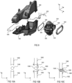
- FIG. 6 an exploded view of a loudspeaker arrangement 600 comprising a first loudspeaker 610, a second loudspeaker 620, a first enclosure part 660 and a second enclosure part 662 is schematically illustrated.
- the first enclosure part 660 is arranged to enclose the first loudspeaker 610
- the second enclosure part 662 is arranged to enclose the second loudspeaker 620.
- Figure 7 schematically illustrates the loudspeaker arrangement 700 in a mounted state, with Figure 7A illustrating a dimensional view and Figure 7B illustrating a front view of the loudspeaker arrangement 700.
- Figure 7C schematically illustrates a side view of the exemplary loudspeaker arrangement 700.
- the second loudspeaker 720 is visible through the opening 732, while the first loudspeaker 710 is concealed by the first enclosure part 760.
- the front side of the first loudspeaker 710 and the front side of the second loudspeaker 720 are visible through the opening 732.
- the loudspeaker enclosure 600, 700 comprising the first enclosure part 660, 760 and the second enclosure part 662, 762 in Figures 6 and 7 is formed to fit into the interior of a vehicle.
- the general form of the enclosure and the individual enclosure parts 660, 760, 662, 762 may vary, depending on whether the loudspeaker arrangement 600, 700 is arranged inside a vehicle, depending on which kind of vehicle the loudspeaker enclosure is arranged in, and depending on the position of the loudspeaker arrangement inside a vehicle, e.g., front part of the passenger compartment, rear part of the passenger compartment, trunk, etc.
- a first elastic cord 642, 742 may be arranged on the third projection 640, 740 and a second elastic cord 646 (not visible in Figure 7 ) may be arranged on the fourth projection 644, for example. That is, the first elastic cord 642, 742 may be arranged to surround the third projection 640, 740 and the second elastic cord 646 may be arranged to surround the fourth projection 644.
- the elastic cords 642, 742, 646 may surround the projections 640, 740, 644 like a tire surrounds a rim, for example.
- the third projection 740 and the fourth projection may be clamped between the first enclosure part 760 and the second enclosure part 762.
- the first enclosure part 1360 and the second enclosure part 1362 when arranged to enclose the first loudspeaker 1310 and the second loudspeaker 1320, may form a first circumferential connection area arranged to surround and clamp the third projection 1340, and a second circumferential connection area arranged to surround and clamp the fourth projection 1344 such that the third projection 1340 and the fourth projection 1344 each are clamped between the first enclosure part 1360 and the second enclosure part 1362.
- the first loudspeaker 1310 and the second loudspeaker 1320 are fixed inside the enclosure. No further points of contact between the loudspeakers 1310, 1320 and the enclosure are generally necessary.
- first loudspeaker 1310 and the second loudspeaker 1320 are fixed inside the enclosure solely by clamping the third projection 1340 and the fourth projection 1344 between the first enclosure part 1360 and the second enclosure part 1362. In this way, the first loudspeaker 1310 and the second loudspeaker 1320 are mechanically decoupled from the first enclosure part 1310 and the second enclosure part 1320.
- any potentially remaining vibrations generated by the loudspeakers 1310, 1320 that are not cancelled out by directly connecting the first loudspeaker 1310 to the second loudspeaker 1320 are at least partly damped or absorbed by suspending the loudspeakers 1310, 1320 within the loudspeaker enclosure (e.g., between first enclosure part 1360 and second enclosure part 1362), as has been described above with respect to Figure 13 .
- the use of screws for fixing the loudspeakers 1310, 1320 inside the enclosure may be entirely avoided.
- screws may become loose over time, as the material of the screws (e.g., metal) usually has a different thermal expansion coefficient than the material of the loudspeakers 1310, 1320 (e.g. plastic or glass fiber) and the material of the enclosure (e.g., plastic or glass fiber).
- the loosening of the screws may lead to unwanted clattering and rattling of the loudspeaker arrangement. Any unwanted noise and clattering may be avoided when fixing the loudspeakers 1310, 1320 inside the enclosure by clamping the third projection 1340 and the fourth projection 1344 between the first enclosure part 1360 and the second enclosure part 1362.
- any vibrations or excitations of the loudspeakers 1310, 1320 may be damped further, for example. Vibrations of the first and second loudspeakers 1310, 1320, therefore, may be completely, or at least almost completely, reduced or avoided. Suspending the loudspeakers 1310, 1320 between the first enclosure part 1360 and the second enclosure part 1362, stiffens (strengthens) the enclosure walls, while at the same time dampening any remaining vibrations. Further, the inside of the enclosure may be sealed towards the outside by means of elastic cords 1342, 1346.
- the first elastic cord 1342 may be arranged between the third projection 1340 and the first and second enclosure parts 1360, 1362
- the second elastic cord 1346 may be arranged between the fourth projection 1344 and the first and second enclosure parts 1360, 1362.
- Figure 12A illustrates a front view of a loudspeaker arrangement in an unmounted state
- Figure 12B illustrates a front view of the loudspeaker arrangement in a mounted state
- the first loudspeaker 1210 and the second loudspeaker 1220 are arranged opposite each other and a first cavity 1230 is formed between the front side of the first loudspeaker 1210 and the front side of the second loudspeaker 1220.
- the first enclosure part 1260 and the second enclosure part 1262 each may have a recess which forms the first circumferential connection area for clamping the third projection 1240.
- a second circumferential connection area for clamping the fourth projection as well as the fourth projection itself are not visible in the front view of Figure 12 .
- the first enclosure part 1260 and the second enclosure part 1262 are arranged to enclose the first loudspeaker 1210 and the second loudspeaker 1220
- the first enclosure part 1260 may be fixed to the second enclosure part 1262.
- the first enclosure part 1260 may be glued to the second enclosure part 1262 in the mounted state.
- a (viscoplastic) adhesive or glue may be applied between the first enclosure part 1260 and the second enclosure part 1262. More specifically, an adhesive or glue may be applied along a contact surface or contact area of the first enclosure part 1260 which is brought into contact with a contact surface or contact area of the second enclosure part 1262. This, however, is only an example.
- the loudspeaker arrangement 800 may further include third connection elements 880 that are configured to connect the first enclosure part 860 to the second enclosure part 862.
- third connection elements 880 are schematically illustrated in Figure 8 .
- Each of the plurality of third connection elements 880 may comprise a screw, a bolt, a bracket, a pin, a hook, or a press-fit pin, for example.
- One example of a third connection element 880 will be described with respect to Figure 10 in more detail below.
- the plurality of third connection elements 880 may be evenly distributed around the enclosure and along the contact area between the first enclosure part 860 and the second enclosure part 862 to equally distribute the resulting holding force along the perimeter of the enclosure.
- a third elastic cord 948 (illustrated in dashed lines in Figure 9 ) may be arranged between the first enclosure part 960 and the second enclosure part 962. In this way, the inside of the enclosure may be further sealed towards the outside. Even further, vibrations and excitations may be further reduced.
- a third elastic cord 948 may be used instead of an adhesive or glue as has been described with respect to Figure 8 above.
- the first enclosure part 960 and the second enclosure part 962 each include a material such as polypropylene or glass fibre, for example.
- the first, second, and third elastic cords 942, 946, 948 each may comprise an elastomer, sponge or foam rubber, or any other foam material, for example.
- the first loudspeaker 810, 910 and the second loudspeaker 820, 920 may be electrically coupled to components or elements arranged outside the enclosure, e.g., to a power supply such as a vehicle battery.
- a cable harness 870, 970 for electrically coupling the first loudspeaker 810, 910 and the second loudspeaker 82, 920 to the outside of the enclosure is exemplarily illustrated in Figures 8 and 9 .
- the enclosure may comprise a further opening (not specifically illustrated) through which such a cable harness 870, 970 may extend from the inside to the outside of the enclosure.
- Figure 10A schematically illustrates a section of the first enclosure part 1060 and a section of the second enclosure part 1062.
- the third elastic cord 1048 is arranged between the first enclosure part 1060 and the second enclosure part 1062.
- Figure 10A illustrates the first enclosure part 1060 and the second enclosure part 1062 in an unmounted state and without a third connection element.
- Figure 10B illustrates the same arrangement as Figure 10A , further comprising a third connection element 1080.
- the third connection element 1080 may comprise a first hook 1081 and a second hook 1082.
- the first hook 1081 may be coupled to the first enclosure part 1060 and the second hook 1082 may be coupled to the second enclosure part 1062.
- Figure 10B also illustrates the arrangement in an unmounted state. The arrows in Figure 10B indicate the direction in which the enclosure parts 1060, 1062 are moved towards each other when connecting the first enclosure part 1060 to the second enclosure part 1062.
- Figure 10C illustrates the arrangement when the first enclosure part 1060 is pressed towards the second enclosure part 1062. This results in the third elastic cord 1048 being compressed.
- the first hook 1081 and the second hook 1082 in the mounted state may overlap in the first direction y.
- a fixing element 1090 may be inserted between the first hook 1081 and the second hook 1082. This is indicated by a small arrow in Figure 10C .
- the first fixing element 1090 is inserted between the first hook 1081 and the second hook 1082, it fixes the first hook 1081 with regard to the second hook 1082 and thereby prevents the removal of the first enclosure part 1060 from the second enclosure part 1062.
- the third elastic cord 1048 exerts an expansion pressure on the first enclosure part 1060 and on the second enclosure part 1062, wherein this expansion pressure would push the first enclosure part 1060 away from the second enclosure part 1062 without the third connection element 1080.
- the third connection element 1080 e.g., the hooks 1081, 1082 with the fixing element 1090 arranged therebetween, prevents the first enclosure part 1060 from being pushed away from the second enclosure part 1062. That is, the third connection element 1080 counteracts the expansion pressure of the compressed third elastic cord 1048 and keeps the first enclosure part 1060 and the second enclosure part 1062 firmly pressed against each other.
- the expansion force exerted by the third elastic cord 1048 forces the hooks 1081, 1082 to move towards each other such that the fixing element 1090 is firmly clamped between the first hook 1081 and the second hook 1082.
- the first enclosure part 1060 and the second enclosure part 1062 each may comprise a notch or an indentation to receive the third elastic cord 1048.
- the third elastic cord 1048 may be prevented from slipping out from between the first enclosure part 1060 and the second enclosure part 1062.
- the third projection 540 and the fourth projection 544 may also comprise a notch or an indentation to receive the first elastic cord 542 and the second elastic cord 546, respectively, and to prevent the elastic cords 542, 546 from slipping off the projections 540, 544.
- FIG. 11A a top view of a third connection element 1080 is exemplarily illustrated.
- the first enclosure part 1160 is visible as well as the first hook 1181.
- the second hook is concealed by the first hook 1181 in this top view as it is arranged below the first hook 1181 in the first direction y (extending vertically into the image plane in the top view of Figure 11A ).
- the fixing element 1190 may have a width w90 in the second direction z that is greater than a width w81 of the first hook 1181 and the second hook 1182 in the same direction z. This may prevent the fixing element 1190 from slipping out from between the first hook 1181 and the second hook 1182 in the second direction z.
- a separate fixing element 1190 may be provided for each pair of hooks 1181, 1182. This, however, is only an example. According to another example, one fixing element 1190 may extend along two or more pairs of hooks 1181, 1182. This is exemplarily illustrated in Figure 11B .
- a thickness w1 of the first enclosure part 1160 and the second enclosure part 1162 in the third direction x may be larger than a maximum extension w2 of the third connection element 1180 in the same direction x.
- the maximum extension w2 of the third connection element 1180 may be 2/3 of the thickness w1 of the first enclosure part 1160 and the second enclosure part 1162.
- the maximum extension w2 of the third connection element 1180 may be 2.5mm, for example. This, however, is only an example.
- the maximum extension w2 of the third connection element 1180 may also be larger or smaller than 2.5mm.
- Figure 12 a cross-sectional view of a loudspeaker arrangement 1200 is exemplarily illustrated, wherein Figure 12A illustrates the loudspeaker arrangement 1200 in an unmounted state and Figure 12B illustrates the loudspeaker arrangement 1200 in a mounted state.
- the first loudspeaker 1210 and the second loudspeaker 1220 are arranged opposite each other in the first direction y, as has been described above.
- a first cavity 1230 is formed between the first loudspeaker 1210 and the second loudspeaker 1220.
- a first enclosure part 1260 and a second enclosure part 1262 are arranged to enclose the first loudspeaker 1210 and the second loudspeaker 1220.
- first loudspeaker 1210 and the second loudspeaker 1220 are clamped between the first enclosure part 1260 and the second enclosure part 1262.
- the third projection 1240 and the fourth projection formed by the first loudspeaker 1210 and the second loudspeaker 1220 are clamped between the first enclosure part 1260 and the second enclosure part 1262.
- the first enclosure part 1260 may exert a pressure on the first loudspeaker 1210
- the second enclosure part 1262 may exert a pressure on the second loudspeaker 1220, for example, thereby pressing the first loudspeaker 1210 and the second loudspeaker 1220 towards each other.
- a first elastic cord 1242 may be arranged between the third projection 1240 and the first and the second enclosure parts 1260, 1262.
- the fourth projection and an optional second elastic cord are not visible in the cross-sectional view of Figure 12 .
- FIG. 13 another cross-sectional view of a loudspeaker arrangement is exemplarily illustrated.
- the opening 1332 of the first cavity 1330 faces in the second direction z.
- both the third projection 1340 and the fourth projection 1344 are visible.
- a first elastic cord 1242 is arranged to surround the third projection 1340
- a second elastic cord 1346 is arranged to surround the fourth projection 1344.
- the arrows illustrated in Figure 13 indicate the direction in which the first enclosure part 1360 and the second enclosure part 1362 exert a pressure on the third projection 1340 and the fourth projection 1344, respectively.
- a third elastic cord 1348 is illustrated between the first enclosure part 1360 and the second enclosure part 1362.
- the loudspeaker arrangement 1300 illustrated in Figure 13 further comprises a third connection element 1380 that is configured to connect the first enclosure part 1360 to the second enclosure part 1362.
- the first, second and third direction x, y, z are used throughout the description for illustrative purposes only.
- the directions are not meant to be defined with regard to a ground surface. Rather, the directions are merely used to illustrate the orientation of the different elements and their arrangement with regard to each other.
- the described loudspeaker arrangement When mounted into a wall or inside a vehicle, the described loudspeaker arrangement may be rotated into any suitable position resulting in any suitable orientation.
- the description of embodiments has been presented for purposes of illustration and description. Suitable modifications and variations to the embodiments may be performed in light of the above description or may be acquired from practicing the methods.
- the described arrangements are exemplary in nature, and may include additional elements and/or omit elements.
Landscapes
- Engineering & Computer Science (AREA)
- Physics & Mathematics (AREA)
- Acoustics & Sound (AREA)
- Signal Processing (AREA)
- Health & Medical Sciences (AREA)
- Otolaryngology (AREA)
- Manufacturing & Machinery (AREA)
- Multimedia (AREA)
- Audible-Bandwidth Dynamoelectric Transducers Other Than Pickups (AREA)
- Fittings On The Vehicle Exterior For Carrying Loads, And Devices For Holding Or Mounting Articles (AREA)
- Details Of Audible-Bandwidth Transducers (AREA)
Description
- The disclosure relates to a loudspeaker arrangement, in particular to a loudspeaker arrangement within a housing.
- Loudspeaker arrangements usually comprise a plurality of different components. A loudspeaker enclosure usually accommodates one or more loudspeakers. The loudspeaker enclosure may be mounted to a wall or, e.g., to a panel in a passenger compartment of a vehicle. The loudspeaker enclosure often is screwed to a wall or a panel, for example. Due to the movement of the loudspeaker membranes, magnets, or any other movable elements within a loudspeaker, other elements such as a loudspeaker enclosure may also be excited and vibrate. Further, different parts and elements of the loudspeaker arrangement may be excited and bump or grate against each other. Vibrations of the loudspeaker arrangement may further be transferred to other parts and elements that are directly or indirectly connected to the loudspeaker arrangement such as, e.g., wall panels or other elements that are arranged close to the loudspeaker arrangement in a vehicle. This may result in unwanted noise which may worsen the sound experience for a user.
- Document
US 2012/008813 A1 discloses a first electro-acoustic transducer and a second electro-acoustic transducer that are supported by a housing attached to a baffle to form an asymmetric acoustical system. An equalizer receives an input signal and generates an equalized signal which is transmitted to the second electro-acoustic transducer. The equalizer is configured to generate the equalized signal such that a net mechanical force acting on the baffle, generated by the first electro-acoustic transducer in response to the input signal and by the second electro-acoustic transducer in response to the equalized signal, is less than the net mechanical force that would be generated if the equalized signal were unchanged in magnitude and equal or opposite in phase to the input signal. - Document
US 2012/219171 A1 discloses loudspeaker assembly for use in a loudspeaker system having infinite baffle topology. The assembly comprises a driver including a cone and a basket and at least one Helmholtz resonator including a chamber and a vent duct communicating with the chamber and adapted to pass through the infinite baffle. The chamber is dimensioned to provide a tuned frequency well above an operating band associated with the driver. The cross sectional area and length of the vent duct may be set to provide control over duct air noise and low frequency extension. - Document
US 6 219 426 B1 discloses a CPS (center point stereo) system directed to stereo sound reinforcement of live music, particularly with electronically-implemented instruments such as guitars and keyboards that provide a musical source signal at line level. A special CPS processor, converting regular left and right stereo signals to sum and difference signals, enables a center stage acoustic image to be created directly from a forward-directed loudspeaker unit driven from the sum signal and enables left and right spatialized stereo images to be created by recombination with a difference field received indirectly from a sideways-directed special dipole loudspeaker unit conveniently co-located with the forward-directed loudspeaker unit and driven from the difference signal. The CPS processor receives L and R input from the instrument or from an interposed FX (musical effects) or DSP (digital sound process) unit receiving mono or stereo input from the instrument. CPS market potential ranges from full CPS systems to unique add-on CPS processors and dipole loudspeaker units as system building blocks. - A loudspeaker arrangement includes a first loudspeaker including a first sound radiating surface and a first loudspeaker basket, and a second loudspeaker including a second sound radiating surface and a second loudspeaker basket. The first loudspeaker and the second loudspeaker are arranged opposite each other in a first direction, a cavity is formed between a front side of the first loudspeaker and a front side of the second loudspeaker, and the first loudspeaker basket is directly coupled to the second loudspeaker basket. The loudspeaker arrangement further comprises a third projection and a fourth projection formed by the first loudspeaker basket and the second loudspeaker basket, and arranged opposite each other in a second direction that is perpendicular to the first direction, and a loudspeaker enclosure comprising a first enclosure part arranged to enclose a rear side of the first loudspeaker, and a second enclosure part arranged to enclose a rear side of the second loudspeaker and to be connected to the first enclosure part, wherein when the first enclosure part and the second enclosure part are arranged to enclose the first and the second loudspeaker, the third projection and the fourth projection each are clamped between the first enclosure part and the second enclosure part. The cavity comprises at least one opening towards the environment in the second direction.
- Preferred embodiments are defined in the dependent claims.
- The arrangement may be better understood with reference to the following description and drawings. The components in the figures are not necessarily to scale, emphasis instead being placed upon illustrating the principles of the invention. Moreover, in the figures, like referenced numerals designate corresponding parts throughout the different views.
-
Figure 1 schematically illustrates a cross-sectional view of a loudspeaker arrangement. -
Figure 2 schematically illustrates a dimensional view of another loudspeaker arrangement. -
Figure 3 schematically illustrates a dimensional view of loudspeakers of a loudspeaker arrangement in an unmounted state. -
Figure 4 schematically illustrates a front view of loudspeakers of an exemplary loudspeaker arrangement. -
Figure 5 schematically illustrates a side view of loudspeakers of an exemplary loudspeaker arrangement. -
Figure 6 schematically illustrates an exploded view of an exemplary loudspeaker arrangement in an unmounted state. -
Figure 7 , includingFigures 7A to 7C , schematically illustrates a dimensional view, a front view and a side view of an exemplary loudspeaker arrangement in a mounted condition. -
Figure 8 schematically illustrates an exploded view of another exemplary loudspeaker arrangement in an unmounted state. -
Figure 9 schematically illustrates an exploded view of another exemplary loudspeaker arrangement in an unmounted state. -
Figure 10 , includingFigures 10A to 10C , schematically illustrates a cross-sectional view of a section of the enclosure walls of a loudspeaker arrangement and of an exemplary connection element in a mounted an in an unmounted state. -
Figure 11 , includingFigures 11A and 11B , schematically illustrates cross-sectional views of an exemplary connection element in a mounted state. -
Figure 12 , includingFigures 12A and 12B , schematically illustrates a side view of an exemplary loudspeaker arrangement in an unmounted and in a mounted state. -
Figure 13 schematically illustrates a cross-sectional view of an exemplary loudspeaker arrangement. - Referring to
Figure 1 , aloudspeaker arrangement 100 is schematically illustrated. In particular,Figure 1 schematically illustrates a cross-sectional view of aloudspeaker arrangement 100. Theloudspeaker arrangement 100 comprises afirst loudspeaker 110 and asecond loudspeaker 120. Thefirst loudspeaker 110 comprises a first sound radiating surface (e.g., a first membrane), and thesecond loudspeaker 120 comprises a second sound radiating surface (e.g., a second membrane). Thefirst loudspeaker 110 and thesecond loudspeaker 120 are arranged opposite each other in a first direction y. That is, a first side of the first sound radiating surface is arranged opposite to and faces a first side of the second sound radiating surface. The first sound radiating surface is arranged essentially parallel to the second sound radiating surface. Not falling under the scope of the claimed invention, a distance d1 between thefirst loudspeaker 110 and thesecond loudspeaker 120 may be between 1cm and 20cm, for example. The distance d1 between thefirst loudspeaker 110 and thesecond loudspeaker 120 may depend on the size of theloudspeakers - A
first cavity 130 is formed between a front side of thefirst loudspeaker 110 and a front side of thesecond loudspeaker 120. Thefirst loudspeaker 110 and thesecond loudspeaker 120 radiate sound into thefirst cavity 130. Thefirst cavity 130 comprises an opening through which sound generated by thefirst loudspeaker 110 and sound generated by thesecond loudspeaker 120 exits thefirst cavity 130 towards the environment. Such an opening, however, is not specifically illustrated in the cross-sectional view ofFigure 1 . - The
loudspeaker arrangement 100 further comprises an enclosure comprising afirst enclosure part 114 and asecond enclosure part 124. Thefirst enclosure part 114 forms a first sealedcavity 112 surrounding a back side of thefirst loudspeaker 110. Thesecond enclosure part 124 forms a second sealedcavity 122 surrounding the back side of thesecond loudspeaker 120. - The
loudspeaker arrangement 100 may, e.g., be mounted into a wall or in a vehicle. Theloudspeaker arrangement 100 illustrated inFigure 1 comprises one pair of loudspeakers, the pair of loudspeakers including thefirst loudspeaker 110 and thesecond loudspeaker 120. This, however, is only an example. It is also possible that a loudspeaker arrangement comprises more than one pair of loudspeakers. This is exemplarily illustrated inFigure 2 which schematically illustrates a dimensional view of aloudspeaker arrangement 200. Theloudspeaker arrangement 200 illustrated inFigure 2 comprises three pairs of loudspeakers, each pair of loudspeakers formed by afirst loudspeaker 210 and a second loudspeaker (not visible in the dimensional view ofFigure 2 ). Any other number of loudspeaker pairs, however, is also possible. - Each pair of loudspeakers may be arranged similarly to what has been described with respect to the loudspeaker pair of
Figure 1 above. Thefirst cavity 230 may be formed continuously between all pairs of loudspeakers, for example. Thefirst enclosure part 214 may enclose allfirst loudspeakers 210 and form a continuous closed cavity at the back side of thefirst loudspeakers 210. However, it is also possible that a separate closed cavity is formed at the back side of each of thefirst loudspeakers 210. The same applies for the second loudspeakers and thesecond enclosure part 224, which may form a single continuous closed cavity at the back side of the second loudspeakers, or separate closed cavities for each of the second loudspeakers. Theopening 232 of thefirst cavity 230 may face towards a second direction z which is perpendicular to the first direction y. If theloudspeaker arrangement 200 comprises two or more pairs of loudspeakers, the pairs of loudspeakers may be arranged successively in a third direction x, which is perpendicular to both the first direction y and the second direction z. - Now referring to the exploded view of
Figure 3 , afirst loudspeaker 310 and asecond loudspeaker 320 are schematically illustrated in an unmounted state. A loudspeaker enclosure is not specifically illustrated inFigure 3 . Thefirst loudspeaker 310 comprises afirst loudspeaker basket 316, and the second loudspeaker comprises asecond loudspeaker basket 326. According to one example not forming part of the invention, thefirst loudspeaker 310 and thesecond loudspeaker 320 may be arranged opposite each other in the first direction y and may be coupled to each other by means of first andsecond connection elements first loudspeaker 310 may comprise a plurality offirst connection elements 352 and a plurality ofsecond connection elements 354. Thesecond loudspeaker 320 may also comprise a plurality offirst connection elements 352 and a plurality ofsecond connection elements 354, wherein eachfirst connection element 352 of thesecond loudspeaker 320 forms a counterpart for asecond connection element 354 of thefirst loudspeaker 310, and eachsecond connection element 354 of thesecond loudspeaker 320 forms a counterpart for afirst connection element 352 of thefirst loudspeaker 310. Thefirst loudspeaker 310 may comprise afirst projection 318. Thefirst projection 318 may extend from thefirst loudspeaker basket 316 in the first direction y towards thesecond loudspeaker 320. Thefirst projection 318, in a plane defined by the second direction z and the third direction x, may at least partly surround the first sound radiating surface. As is schematically illustrated inFigure 3 , thefirst projection 318 may be omitted towards one side, in order to form the opening 332. Thesecond loudspeaker 320 may comprise asecond projection 328. Thesecond projection 328 may extend from thesecond loudspeaker basket 326 in the first direction y towards thefirst loudspeaker 310. Thesecond projection 328, in a plane defined by the second direction z and the third direction x, may at least partly surround the second sound radiating surface. As is schematically illustrated inFigure 3 , thesecond projection 328 may be omitted towards one side, in order to form the opening 332. Thefirst connection elements 352 and thesecond connection elements 354 may be arranged along thefirst projection 318 and thesecond projection 328, respectively. When thefirst loudspeaker 310 and thesecond loudspeaker 320 are coupled to each other, thefirst projection 318 and thesecond projection 328 may be coupled to each other, thereby connecting thefirst loudspeaker basket 316 to thesecond loudspeaker basket 326. The first cavity 330 may be defined by the first and thesecond projection second projection - According to one example, when the
first loudspeaker 310 and thesecond loudspeaker 320 are mounted together (interconnected), eachfirst counterpart 352 may engage with (e.g., snap into) one of thesecond counterparts 354 of theopposite loudspeaker second connection elements second connection elements first loudspeaker 310 and thesecond loudspeaker 320, the first cavity 330 is formed between thefirst loudspeaker 310 and thesecond loudspeaker 320, with an opening 332 formed towards the second direction z. - The
first loudspeaker 310 and thesecond loudspeaker 320 during use (e.g., when the first sound radiating surface and the second sound radiating surface are excited in order to produce sound) both generate vibrations. According to the invention, by directly connecting thefirst loudspeaker basket 316 to thesecond loudspeaker basket 326, the vibrations of the twoloudspeakers loudspeakers first loudspeaker 310 and thesecond loudspeaker 320, are zero or at least close to zero. Therefore, almost zero vibration is transferred to any surround parts such as a loudspeaker enclosure, for example. - A
first loudspeaker 410 and asecond loudspeaker 420 in a mounted state are exemplarily illustrated in the front view ofFigure 4 and in the side view ofFigure 5 . As can be seen in the side view ofFigure 5 for example, when thefirst loudspeaker 510 is connected to thesecond loudspeaker 520, athird projection 540 and afourth projection 544 are formed by thefirst loudspeaker 510 and thesecond loudspeaker 520. Thethird projection 540 extends from the loudspeaker arrangement 500 in the second direction z, and thefourth projection 544 extends from the loudspeaker arrangement 500 in the second direction z, opposite to thefirst projection 540. According to one example, thethird projection 540 may be formed by thefirst loudspeaker basket 516 or thefirst projection 518 and thesecond loudspeaker basket 526 or thesecond projection 528, and thefourth projection 544 may also be formed by thefirst loudspeaker basket 516 or thefirst projection 518 and by thesecond loudspeaker basket 526 or thesecond projection 528. For example, an upper half of thethird projection 540 and an upper half of thefourth projection 544 may be formed by the first loudspeaker 510 (first loudspeaker basket 516 or first projection 518), and a lower half of thethird projection 540 and a lower half of thefourth projection 544 may be formed by the second loudspeaker 520 (second loudspeaker basket 526 or second projection 528). - Each of the
third projection fourth projection 444, 544 may comprise a protruding edge or ledge, for example. Thethird projection opening 432 of thefirst cavity 430 in a plane defined by the second and third direction z, x, for example. As is schematically illustrated inFigure 4 , theopening 432 may have an elongated form (cross-section), e.g., rectangular with rounded corners. Any other form (cross-section) of theopening 432, however, is also possible such as, square, rectangular, rounded, or oval, for example. Again referring toFigure 5 , thefourth projection 544 is arranged opposite to thethird projection 540 in the second direction z. That is, thefourth projection 544 may be arranged at a rear wall of the first cavity 530 and thethird projection 540 may be arranged at the front of the first cavity 530, for example. This, however, is only an example. According to another example (not illustrated), thethird projection 540 may be arranged at a first side wall of the first cavity 530 and thefourth projection 544 may be arranged at a second side wall of thefirst cavity 430, for example. In the latter case, however, thethird projection 540 may not surround theopening 532 of the first cavity 530. - Now referring to
Figure 6 , an exploded view of a loudspeaker arrangement 600 comprising afirst loudspeaker 610, asecond loudspeaker 620, afirst enclosure part 660 and asecond enclosure part 662 is schematically illustrated. When fully assembled, thefirst enclosure part 660 is arranged to enclose thefirst loudspeaker 610 and thesecond enclosure part 662 is arranged to enclose thesecond loudspeaker 620.Figure 7 schematically illustrates the loudspeaker arrangement 700 in a mounted state, withFigure 7A illustrating a dimensional view andFigure 7B illustrating a front view of the loudspeaker arrangement 700.Figure 7C schematically illustrates a side view of the exemplary loudspeaker arrangement 700. InFigure 7A , thesecond loudspeaker 720 is visible through theopening 732, while thefirst loudspeaker 710 is concealed by thefirst enclosure part 760. InFigure 7B , the front side of thefirst loudspeaker 710 and the front side of thesecond loudspeaker 720 are visible through theopening 732. The loudspeaker enclosure 600, 700 comprising thefirst enclosure part second enclosure part Figures 6 and7 is formed to fit into the interior of a vehicle. The general form of the enclosure and theindividual enclosure parts - As is illustrated in
Figures 6 and7 , a firstelastic cord third projection 640, 740 and a second elastic cord 646 (not visible inFigure 7 ) may be arranged on thefourth projection 644, for example. That is, the firstelastic cord third projection 640, 740 and the secondelastic cord 646 may be arranged to surround thefourth projection 644. Theelastic cords projections - When the
enclosure parts loudspeakers first enclosure part 760 and thesecond enclosure part 762. - This is exemplarily illustrated in more detail in the cross-sectional view of
Figure 13 . Thefirst enclosure part 1360 and thesecond enclosure part 1362 when arranged to enclose thefirst loudspeaker 1310 and thesecond loudspeaker 1320, may form a first circumferential connection area arranged to surround and clamp thethird projection 1340, and a second circumferential connection area arranged to surround and clamp thefourth projection 1344 such that thethird projection 1340 and thefourth projection 1344 each are clamped between thefirst enclosure part 1360 and thesecond enclosure part 1362. In this way, according to the invention, thefirst loudspeaker 1310 and thesecond loudspeaker 1320 are fixed inside the enclosure. No further points of contact between theloudspeakers first loudspeaker 1310 and thesecond loudspeaker 1320 are fixed inside the enclosure solely by clamping thethird projection 1340 and thefourth projection 1344 between thefirst enclosure part 1360 and thesecond enclosure part 1362. In this way, thefirst loudspeaker 1310 and thesecond loudspeaker 1320 are mechanically decoupled from thefirst enclosure part 1310 and thesecond enclosure part 1320. - According to the invention, still referring to
Figure 13 , and as has been described above (see alsoFigure 3 ), most if not all vibrations generated during use of theloudspeakers Figure 13 ) to the second loudspeaker 1320 (second loudspeaker basket, not specifically illustrated inFigure 13 ). Any potentially remaining vibrations generated by theloudspeakers first loudspeaker 1310 to thesecond loudspeaker 1320 are at least partly damped or absorbed by suspending theloudspeakers first enclosure part 1360 and second enclosure part 1362), as has been described above with respect toFigure 13 . - Further, in the exemplary arrangement, the use of screws for fixing the
loudspeakers loudspeakers 1310, 1320 (e.g. plastic or glass fiber) and the material of the enclosure (e.g., plastic or glass fiber). The loosening of the screws may lead to unwanted clattering and rattling of the loudspeaker arrangement. Any unwanted noise and clattering may be avoided when fixing theloudspeakers third projection 1340 and thefourth projection 1344 between thefirst enclosure part 1360 and thesecond enclosure part 1362. - If an
elastic cord projection enclosure parts loudspeakers second loudspeakers loudspeakers first enclosure part 1360 and thesecond enclosure part 1362, stiffens (strengthens) the enclosure walls, while at the same time dampening any remaining vibrations. Further, the inside of the enclosure may be sealed towards the outside by means ofelastic cords elastic cord 1342 may be arranged between thethird projection 1340 and the first andsecond enclosure parts elastic cord 1346 may be arranged between thefourth projection 1344 and the first andsecond enclosure parts - Now referring to the front views of
Figure 12 , the basic principle of an exemplary loudspeaker arrangement is further illustrated.Figure 12A illustrates a front view of a loudspeaker arrangement in an unmounted state, andFigure 12B illustrates a front view of the loudspeaker arrangement in a mounted state. Thefirst loudspeaker 1210 and thesecond loudspeaker 1220 are arranged opposite each other and afirst cavity 1230 is formed between the front side of thefirst loudspeaker 1210 and the front side of thesecond loudspeaker 1220. Thefirst enclosure part 1260 and thesecond enclosure part 1262 each may have a recess which forms the first circumferential connection area for clamping the third projection 1240. A second circumferential connection area for clamping the fourth projection as well as the fourth projection itself are not visible in the front view ofFigure 12 . - When the
first enclosure part 1260 and thesecond enclosure part 1262 are arranged to enclose thefirst loudspeaker 1210 and thesecond loudspeaker 1220, thefirst enclosure part 1260 may be fixed to thesecond enclosure part 1262. According to one example, thefirst enclosure part 1260 may be glued to thesecond enclosure part 1262 in the mounted state. For example, a (viscoplastic) adhesive or glue may be applied between thefirst enclosure part 1260 and thesecond enclosure part 1262. More specifically, an adhesive or glue may be applied along a contact surface or contact area of thefirst enclosure part 1260 which is brought into contact with a contact surface or contact area of thesecond enclosure part 1262. This, however, is only an example. - Now referring to the exploded view of
Figure 8 , the loudspeaker arrangement 800 may further includethird connection elements 880 that are configured to connect thefirst enclosure part 860 to thesecond enclosure part 862. A plurality ofthird connection elements 880 are schematically illustrated inFigure 8 . Each of the plurality ofthird connection elements 880 may comprise a screw, a bolt, a bracket, a pin, a hook, or a press-fit pin, for example. One example of athird connection element 880 will be described with respect toFigure 10 in more detail below. The plurality ofthird connection elements 880 may be evenly distributed around the enclosure and along the contact area between thefirst enclosure part 860 and thesecond enclosure part 862 to equally distribute the resulting holding force along the perimeter of the enclosure. - Now referring to
Figure 9 , a third elastic cord 948 (illustrated in dashed lines inFigure 9 ) may be arranged between thefirst enclosure part 960 and thesecond enclosure part 962. In this way, the inside of the enclosure may be further sealed towards the outside. Even further, vibrations and excitations may be further reduced. A thirdelastic cord 948 may be used instead of an adhesive or glue as has been described with respect toFigure 8 above. - According to one example, the
first enclosure part 960 and thesecond enclosure part 962 each include a material such as polypropylene or glass fibre, for example. The firstelastic cord 942, the secondelastic cord 946 and the thirdelastic cord 948 each may comprise an elastic material that may be compacted or compressed up to a maximum of 50% of its original volume (original volume = when no pressure is exerted on the elastic cord). The first, second, and thirdelastic cords - The
first loudspeaker second loudspeaker cable harness first loudspeaker second loudspeaker 82, 920 to the outside of the enclosure is exemplarily illustrated inFigures 8 and9 . The enclosure may comprise a further opening (not specifically illustrated) through which such acable harness - Now referring to the cross-section of
Figure 10 , athird connection element 1080 according to one example is described in further detail.Figure 10A schematically illustrates a section of thefirst enclosure part 1060 and a section of thesecond enclosure part 1062. The thirdelastic cord 1048 is arranged between thefirst enclosure part 1060 and thesecond enclosure part 1062.Figure 10A illustrates thefirst enclosure part 1060 and thesecond enclosure part 1062 in an unmounted state and without a third connection element.Figure 10B illustrates the same arrangement asFigure 10A , further comprising athird connection element 1080. Thethird connection element 1080 may comprise afirst hook 1081 and asecond hook 1082. Thefirst hook 1081 may be coupled to thefirst enclosure part 1060 and thesecond hook 1082 may be coupled to thesecond enclosure part 1062.Figure 10B also illustrates the arrangement in an unmounted state. The arrows inFigure 10B indicate the direction in which theenclosure parts first enclosure part 1060 to thesecond enclosure part 1062. -
Figure 10C illustrates the arrangement when thefirst enclosure part 1060 is pressed towards thesecond enclosure part 1062. This results in the thirdelastic cord 1048 being compressed. Thefirst hook 1081 and thesecond hook 1082 in the mounted state may overlap in the first direction y. A fixingelement 1090 may be inserted between thefirst hook 1081 and thesecond hook 1082. This is indicated by a small arrow inFigure 10C . When thefirst fixing element 1090 is inserted between thefirst hook 1081 and thesecond hook 1082, it fixes thefirst hook 1081 with regard to thesecond hook 1082 and thereby prevents the removal of thefirst enclosure part 1060 from thesecond enclosure part 1062. The thirdelastic cord 1048 exerts an expansion pressure on thefirst enclosure part 1060 and on thesecond enclosure part 1062, wherein this expansion pressure would push thefirst enclosure part 1060 away from thesecond enclosure part 1062 without thethird connection element 1080. However, thethird connection element 1080, e.g., thehooks element 1090 arranged therebetween, prevents thefirst enclosure part 1060 from being pushed away from thesecond enclosure part 1062. That is, thethird connection element 1080 counteracts the expansion pressure of the compressed thirdelastic cord 1048 and keeps thefirst enclosure part 1060 and thesecond enclosure part 1062 firmly pressed against each other. The expansion force exerted by the thirdelastic cord 1048, on the other hand, forces thehooks element 1090 is firmly clamped between thefirst hook 1081 and thesecond hook 1082. - As is exemplarily illustrated in
Figure 10 , thefirst enclosure part 1060 and thesecond enclosure part 1062 each may comprise a notch or an indentation to receive the thirdelastic cord 1048. In this way, the thirdelastic cord 1048 may be prevented from slipping out from between thefirst enclosure part 1060 and thesecond enclosure part 1062. - As is implied in
Figure 5 , for example, thethird projection 540 and thefourth projection 544, optionally, may also comprise a notch or an indentation to receive the first elastic cord 542 and the second elastic cord 546, respectively, and to prevent the elastic cords 542, 546 from slipping off theprojections - Now referring to
Figure 11A , a top view of athird connection element 1080 is exemplarily illustrated. In the cross-sectional view ofFigure 11A , thefirst enclosure part 1160 is visible as well as thefirst hook 1181. The second hook is concealed by thefirst hook 1181 in this top view as it is arranged below thefirst hook 1181 in the first direction y (extending vertically into the image plane in the top view ofFigure 11A ). The fixingelement 1190 may have a width w90 in the second direction z that is greater than a width w81 of thefirst hook 1181 and the second hook 1182 in the same direction z. This may prevent thefixing element 1190 from slipping out from between thefirst hook 1181 and the second hook 1182 in the second direction z. According to the example illustrated inFigure 11A , aseparate fixing element 1190 may be provided for each pair ofhooks 1181, 1182. This, however, is only an example. According to another example, onefixing element 1190 may extend along two or more pairs ofhooks 1181, 1182. This is exemplarily illustrated inFigure 11B . - As is further illustrated in
Figure 11A , a thickness w1 of thefirst enclosure part 1160 and the second enclosure part 1162 in the third direction x may be larger than a maximum extension w2 of the third connection element 1180 in the same direction x. For example, the maximum extension w2 of the third connection element 1180 may be 2/3 of the thickness w1 of thefirst enclosure part 1160 and the second enclosure part 1162. The maximum extension w2 of the third connection element 1180 may be 2.5mm, for example. This, however, is only an example. The maximum extension w2 of the third connection element 1180 may also be larger or smaller than 2.5mm. - Now referring to
Figure 12 , a cross-sectional view of aloudspeaker arrangement 1200 is exemplarily illustrated, whereinFigure 12A illustrates theloudspeaker arrangement 1200 in an unmounted state andFigure 12B illustrates theloudspeaker arrangement 1200 in a mounted state. Thefirst loudspeaker 1210 and thesecond loudspeaker 1220 are arranged opposite each other in the first direction y, as has been described above. Afirst cavity 1230 is formed between thefirst loudspeaker 1210 and thesecond loudspeaker 1220. Afirst enclosure part 1260 and asecond enclosure part 1262 are arranged to enclose thefirst loudspeaker 1210 and thesecond loudspeaker 1220. In a mounted state, thefirst loudspeaker 1210 and thesecond loudspeaker 1220 are clamped between thefirst enclosure part 1260 and thesecond enclosure part 1262. In particular, the third projection 1240 and the fourth projection formed by thefirst loudspeaker 1210 and thesecond loudspeaker 1220 are clamped between thefirst enclosure part 1260 and thesecond enclosure part 1262. Thefirst enclosure part 1260 may exert a pressure on thefirst loudspeaker 1210, and thesecond enclosure part 1262 may exert a pressure on thesecond loudspeaker 1220, for example, thereby pressing thefirst loudspeaker 1210 and thesecond loudspeaker 1220 towards each other. As has been described before, a firstelastic cord 1242 may be arranged between the third projection 1240 and the first and thesecond enclosure parts Figure 12 . - Now referring to
Figure 13 , another cross-sectional view of a loudspeaker arrangement is exemplarily illustrated. In the cross-sectional view ofFigure 13 , theopening 1332 of thefirst cavity 1330 faces in the second direction z. InFigure 13 , both thethird projection 1340 and thefourth projection 1344 are visible. A firstelastic cord 1242 is arranged to surround thethird projection 1340, and a secondelastic cord 1346 is arranged to surround thefourth projection 1344. The arrows illustrated inFigure 13 indicate the direction in which thefirst enclosure part 1360 and thesecond enclosure part 1362 exert a pressure on thethird projection 1340 and thefourth projection 1344, respectively. Further, inFigure 13 , a thirdelastic cord 1348 is illustrated between thefirst enclosure part 1360 and thesecond enclosure part 1362. The loudspeaker arrangement 1300 illustrated inFigure 13 further comprises athird connection element 1380 that is configured to connect thefirst enclosure part 1360 to thesecond enclosure part 1362. - The first, second and third direction x, y, z are used throughout the description for illustrative purposes only. The directions are not meant to be defined with regard to a ground surface. Rather, the directions are merely used to illustrate the orientation of the different elements and their arrangement with regard to each other. When mounted into a wall or inside a vehicle, the described loudspeaker arrangement may be rotated into any suitable position resulting in any suitable orientation. The description of embodiments has been presented for purposes of illustration and description. Suitable modifications and variations to the embodiments may be performed in light of the above description or may be acquired from practicing the methods. The described arrangements are exemplary in nature, and may include additional elements and/or omit elements. As used in this application, an element recited in the singular and proceeded with the word "a" or "an" should be understood as not excluding plural of said elements, unless such exclusion is stated. Furthermore, references to "one embodiment" or "one example" of the present disclosure are not intended to be interpreted as excluding the existence of additional embodiments that also incorporate the recited features. The terms "first," "second," and "third," etc. are used merely as labels, and are not intended to impose numerical requirements or a particular positional order on their objects. The described systems are exemplary in nature, and may include additional elements and/or omit elements.
Claims (13)
- A loudspeaker arrangement (300) comprising:a first loudspeaker (310) comprising a first sound radiating surface and a first speaker basket (316), anda second loudspeaker (320) comprising a second sound radiating surface and a second speaker basket (326), wherein,the first loudspeaker (310) and the second loudspeaker (320) are arranged opposite each other in a first direction (y);a cavity (330) is formed between a front side of the first loudspeaker (310) and a front side of the second loudspeaker (320);the first loudspeaker basket (316) is directly coupled to the second loudspeaker basket (326);a third projection (1340) and a fourth projection (1344) formed by the first loudspeaker basket (316) and the second loudspeaker basket (326), and arranged opposite each other in a second direction (z) that is perpendicular to the first direction (y); anda loudspeaker enclosure comprising a first enclosure part (1360) arranged to enclose a rear side of the first loudspeaker (310, 1310), and a second enclosure part (1362) arranged to enclose a rear side of the second loudspeaker (320, 1320) and to be connected to the first enclosure part (1360), whereinwhen the first enclosure part (1360) and the second enclosure part (1362) are arranged to enclose the first and the second loudspeaker (310, 320, 1310, 1320), the third projection (1340) and the fourth projection (1344) each are clamped between the first enclosure part (1360) and the second enclosure part (1362), andthe cavity (330, 1330) comprises at least one opening (332, 1332) towards the environment in the second direction (z).
- The loudspeaker arrangement (300) of claim 1, whereinthe first loudspeaker basket (316) comprises a first projection (318) extending from the first loudspeaker basket (316) in the first direction (y) towards the second loudspeaker (320);the second loudspeaker basket (326) comprises a second projection (328) extending from the second loudspeaker basket (326) in the first direction (y) towards the first loudspeaker (310); andthe first projection (318) is directly coupled to the second projection (328), thereby defining the cavity between the front side of the first loudspeaker (310) and the front side of the second loudspeaker (320).
- The loudspeaker arrangement (300, 1300) of claim 1 or 2, further comprising a first elastic cord (1342) mounted on the third projection (1340) to circumferentially surround the third projection (1340), and a second elastic cord (1346) mounted on the fourth projection (1344) to circumferentially surround the fourth projection (1344), wherein, when the first enclosure part (1360) and the second enclosure part (1362) are arranged to enclose the first and the second loudspeaker (310, 320, 1310, 1320), the first elastic cord (1342) is arranged between the third projection (1340) and the loudspeaker enclosure, and the second elastic cord (1346) is arranged between the fourth projection (1344) and the loudspeaker enclosure.
- The loudspeaker arrangement (300, 1300) of any of claims 1 to 3, wherein the first loudspeaker (310, 1310) and the second loudspeaker (320, 1320) are arranged such that the first sound radiating surface and the second sound radiating surface are arranged substantially in parallel to each other.
- The loudspeaker arrangement (300, 1300) of any of claims 3 to 4, wherein, when the loudspeaker enclosure is arranged to enclose the first loudspeaker (310, 1310) and the second loudspeaker (320, 1320), the first enclosure part (1360) and the second enclosure part (1362) exert pressure on the first elastic cord (1342) and the third projection (1340), and the first enclosure part (1360) and the second enclosure part (1362) further exert pressure on the second elastic cord (1346) and the fourth projection (1344), thereby fixating the first loudspeaker (1310) and the second loudspeaker (1320) within the enclosure.
- The loudspeaker arrangement (300, 1300) of claim 5, wherein,when pressure is exerted on the first elastic cord (1342), the first elastic cord (1342) is compressed up to a maximum of 50%; andwhen pressure is exerted on the second elastic cord (1346), the second elastic cord (1346) is compressed up to a maximum of 50%.
- The loudspeaker arrangement (300, 1300) of any of the preceding claims, further comprising a plurality of first connection elements (352) and a plurality of second connection elements (354) configured to connect the first loudspeaker basket (316) to the second loudspeaker basket (326).
- The loudspeaker arrangement (300, 1300) of any of claims 1 to 7, further comprising a third elastic cord (948, 1348) arranged between the first enclosure part (1360) and the second enclosure part (1362).
- The loudspeaker arrangement (300, 1300) of any of claims 3 to 8, wherein at least one ofthe first elastic cord (1342) comprises an elastomer, sponge or foam rubber, or a foam material;the second elastic cord (1346) comprises an elastomer, sponge or foam rubber, or a foam material; andthe third elastic cord (1348) comprises an elastomer, sponge or foam rubber, or a foam material.
- The loudspeaker arrangement (300, 1300) of any of claims 1 to 9, further comprising a plurality of third connection elements (880, 1380) that are configured to connect the first enclosure part (860, 1360) to the second enclosure part (862, 1362).
- The loudspeaker arrangement (300, 1300) of claim 10, wherein the plurality of third connection elements (880, 1380) is evenly distributed around the loudspeaker enclosure and along a contact area between the first enclosure part (860, 1360) and the second enclosure part (862, 1362) to equally distribute the resulting holding force along a perimeter of the loudspeaker enclosure.
- The loudspeaker arrangement (300, 1300) of claim 10 or 11, wherein each of the plurality of third connection elements (880, 1380) comprises a first hook (1081) attached to the first enclosure part (1060, 1360), a second hook (1082) attached to the second enclosure part (1062, 1362) and a fixing element (1090).
- The loudspeaker arrangement (300, 1300) of claim 12, wherein, when the first enclosure part (1060, 1360) is connected to the second enclosure part (1062, 1362), for each of the plurality of third connection elements (1080) the respective first hook (1081) and second hook (1082) overlap in the first direction (y), and the fixing element (1090) is inserted between the first hook (1081) and the second hook (1082).
Priority Applications (3)
| Application Number | Priority Date | Filing Date | Title |
|---|---|---|---|
| EP19169138.5A EP3726849B1 (en) | 2019-04-15 | 2019-04-15 | Loudspeaker arrangement |
| US16/830,589 US11218797B2 (en) | 2019-04-15 | 2020-03-26 | Opposing loudspeaker arrangement |
| CN202010289087.4A CN111836161B (en) | 2019-04-15 | 2020-04-14 | Speaker arrangement |
Applications Claiming Priority (1)
| Application Number | Priority Date | Filing Date | Title |
|---|---|---|---|
| EP19169138.5A EP3726849B1 (en) | 2019-04-15 | 2019-04-15 | Loudspeaker arrangement |
Publications (2)
| Publication Number | Publication Date |
|---|---|
| EP3726849A1 EP3726849A1 (en) | 2020-10-21 |
| EP3726849B1 true EP3726849B1 (en) | 2024-07-24 |
Family
ID=66182356
Family Applications (1)
| Application Number | Title | Priority Date | Filing Date |
|---|---|---|---|
| EP19169138.5A Active EP3726849B1 (en) | 2019-04-15 | 2019-04-15 | Loudspeaker arrangement |
Country Status (3)
| Country | Link |
|---|---|
| US (1) | US11218797B2 (en) |
| EP (1) | EP3726849B1 (en) |
| CN (1) | CN111836161B (en) |
Families Citing this family (3)
| Publication number | Priority date | Publication date | Assignee | Title |
|---|---|---|---|---|
| CN113179466B (en) * | 2021-04-22 | 2022-07-01 | 深圳市瀚宏数码科技有限公司 | Sound box convenient to disassemble and easy to prevent dust |
| EP4416936A1 (en) * | 2021-10-15 | 2024-08-21 | Harman Becker Automotive Systems GmbH | Loudspeaker arrangement |
| EP4207797A1 (en) * | 2021-12-30 | 2023-07-05 | Harman Becker Automotive Systems GmbH | Loudspeaker |
Family Cites Families (12)
| Publication number | Priority date | Publication date | Assignee | Title |
|---|---|---|---|---|
| DE3414407C2 (en) * | 1984-04-17 | 1986-02-20 | Jürgen 6804 Ilvesheim Quaas | Arrangement of sound transducers in a sound guide, in particular for loudspeaker boxes |
| EP0361445A3 (en) * | 1988-09-28 | 1991-05-22 | Yamaha Corporation | Acoustic apparatus |
| US5561717A (en) * | 1994-03-15 | 1996-10-01 | American Trading And Production Corporation | Loudspeaker system |
| US6219426B1 (en) * | 1996-08-08 | 2001-04-17 | Drew Daniels | Center point stereo field expander for amplified musical instruments |
| RU2186470C2 (en) * | 1997-10-10 | 2002-07-27 | Самсунг Электроникс Ко., Лтд. | Omnidirectional acoustic system |
| US7551749B2 (en) * | 2002-08-23 | 2009-06-23 | Bose Corporation | Baffle vibration reducing |
| KR20080101265A (en) * | 2007-05-16 | 2008-11-21 | 주식회사 대우일렉트로닉스 | Anti-vibration speaker |
| US8804991B2 (en) * | 2009-10-23 | 2014-08-12 | Blueprint Acoustics Pty Ltd | Loudspeaker assembly and system |
| CN201528419U (en) * | 2009-10-30 | 2010-07-14 | 张恒敬 | Handy multi-track combined sound box |
| CA2931551A1 (en) * | 2015-05-28 | 2016-11-28 | Joseph Y. Sahyoun | Passive acoustic radiator module |
| JP2018082413A (en) * | 2016-11-19 | 2018-05-24 | 愛弥 佐藤 | Speaker system |
| JP7022591B2 (en) * | 2018-01-10 | 2022-02-18 | 株式会社デンソーテン | Speaker device |
-
2019
- 2019-04-15 EP EP19169138.5A patent/EP3726849B1/en active Active
-
2020
- 2020-03-26 US US16/830,589 patent/US11218797B2/en active Active
- 2020-04-14 CN CN202010289087.4A patent/CN111836161B/en active Active
Also Published As
| Publication number | Publication date |
|---|---|
| CN111836161B (en) | 2024-09-10 |
| US20200329301A1 (en) | 2020-10-15 |
| EP3726849A1 (en) | 2020-10-21 |
| CN111836161A (en) | 2020-10-27 |
| US11218797B2 (en) | 2022-01-04 |
Similar Documents
| Publication | Publication Date | Title |
|---|---|---|
| EP3726849B1 (en) | Loudspeaker arrangement | |
| EP2087768B1 (en) | In-plane speaker | |
| US6985593B2 (en) | Baffle vibration reducing | |
| EP2291000B1 (en) | Passive acoustic radiating | |
| US8477966B2 (en) | In-wall sub-woofer with high-volume displacement | |
| WO2008064294A2 (en) | Passive acoustical radiating | |
| IL123487A (en) | Loudspeakers comprising panel-form acoustic radiating elements | |
| US11451903B2 (en) | System for reducing vibrations in loudspeaker | |
| US20220363202A1 (en) | Externally coupled loudspeaker assembly for a vehicle | |
| CN108781315B (en) | Loudspeaker module with different module housing geometries and similar acoustic characteristics | |
| EP4246999A1 (en) | Audio device | |
| TW201947944A (en) | Composite speaker module and speaker device | |
| JP7474518B2 (en) | Audio Loudspeaker System | |
| WO2023061610A1 (en) | Loudspeaker arrangement | |
| JP6641939B2 (en) | Bracket and mounting structure of functional device having the same | |
| US11849297B2 (en) | Balanced acoustic device with passive radiators | |
| JP2007067462A (en) | Speaker mounting structure |
Legal Events
| Date | Code | Title | Description |
|---|---|---|---|
| PUAI | Public reference made under article 153(3) epc to a published international application that has entered the european phase |
Free format text: ORIGINAL CODE: 0009012 |
|
| STAA | Information on the status of an ep patent application or granted ep patent |
Free format text: STATUS: THE APPLICATION HAS BEEN PUBLISHED |
|
| AK | Designated contracting states |
Kind code of ref document: A1 Designated state(s): AL AT BE BG CH CY CZ DE DK EE ES FI FR GB GR HR HU IE IS IT LI LT LU LV MC MK MT NL NO PL PT RO RS SE SI SK SM TR |
|
| AX | Request for extension of the european patent |
Extension state: BA ME |
|
| STAA | Information on the status of an ep patent application or granted ep patent |
Free format text: STATUS: REQUEST FOR EXAMINATION WAS MADE |
|
| 17P | Request for examination filed |
Effective date: 20210421 |
|
| RBV | Designated contracting states (corrected) |
Designated state(s): AL AT BE BG CH CY CZ DE DK EE ES FI FR GB GR HR HU IE IS IT LI LT LU LV MC MK MT NL NO PL PT RO RS SE SI SK SM TR |
|
| STAA | Information on the status of an ep patent application or granted ep patent |
Free format text: STATUS: EXAMINATION IS IN PROGRESS |
|
| 17Q | First examination report despatched |
Effective date: 20220906 |
|
| GRAP | Despatch of communication of intention to grant a patent |
Free format text: ORIGINAL CODE: EPIDOSNIGR1 |
|
| STAA | Information on the status of an ep patent application or granted ep patent |
Free format text: STATUS: GRANT OF PATENT IS INTENDED |
|
| GRAS | Grant fee paid |
Free format text: ORIGINAL CODE: EPIDOSNIGR3 |
|
| INTG | Intention to grant announced |
Effective date: 20240523 |
|
| AK | Designated contracting states |
Kind code of ref document: B1 Designated state(s): AL AT BE BG CH CY CZ DE DK EE ES FI FR GB GR HR HU IE IS IT LI LT LU LV MC MK MT NL NO PL PT RO RS SE SI SK SM TR |
|
| REG | Reference to a national code |
Ref country code: GB Ref legal event code: FG4D |
|
| P01 | Opt-out of the competence of the unified patent court (upc) registered |
Free format text: CASE NUMBER: APP_36745/2024 Effective date: 20240620 |
|
| REG | Reference to a national code |
Ref country code: CH Ref legal event code: EP |
|
| REG | Reference to a national code |
Ref country code: DE Ref legal event code: R096 Ref document number: 602019055600 Country of ref document: DE |
|
| REG | Reference to a national code |
Ref country code: IE Ref legal event code: FG4D |