EP3726709A1 - Squirrel-cage induction rotating electric machine, solid rotor, and squirrel-cage induction rotating electric machine design method - Google Patents
Squirrel-cage induction rotating electric machine, solid rotor, and squirrel-cage induction rotating electric machine design method Download PDFInfo
- Publication number
- EP3726709A1 EP3726709A1 EP17934525.1A EP17934525A EP3726709A1 EP 3726709 A1 EP3726709 A1 EP 3726709A1 EP 17934525 A EP17934525 A EP 17934525A EP 3726709 A1 EP3726709 A1 EP 3726709A1
- Authority
- EP
- European Patent Office
- Prior art keywords
- rotor
- slots
- stator
- squirrel
- core part
- Prior art date
- Legal status (The legal status is an assumption and is not a legal conclusion. Google has not performed a legal analysis and makes no representation as to the accuracy of the status listed.)
- Granted
Links
Images





Classifications
-
- H—ELECTRICITY
- H02—GENERATION; CONVERSION OR DISTRIBUTION OF ELECTRIC POWER
- H02K—DYNAMO-ELECTRIC MACHINES
- H02K7/00—Arrangements for handling mechanical energy structurally associated with dynamo-electric machines, e.g. structural association with mechanical driving motors or auxiliary dynamo-electric machines
- H02K7/003—Couplings; Details of shafts
-
- H—ELECTRICITY
- H02—GENERATION; CONVERSION OR DISTRIBUTION OF ELECTRIC POWER
- H02K—DYNAMO-ELECTRIC MACHINES
- H02K15/00—Processes or apparatus specially adapted for manufacturing, assembling, maintaining or repairing of dynamo-electric machines
- H02K15/02—Processes or apparatus specially adapted for manufacturing, assembling, maintaining or repairing of dynamo-electric machines of stator or rotor bodies
- H02K15/021—Magnetic cores
- H02K15/023—Cage rotors
-
- H—ELECTRICITY
- H02—GENERATION; CONVERSION OR DISTRIBUTION OF ELECTRIC POWER
- H02K—DYNAMO-ELECTRIC MACHINES
- H02K17/00—Asynchronous induction motors; Asynchronous induction generators
- H02K17/02—Asynchronous induction motors
- H02K17/16—Asynchronous induction motors having rotors with internally short-circuited windings, e.g. cage rotors
- H02K17/20—Asynchronous induction motors having rotors with internally short-circuited windings, e.g. cage rotors having deep-bar rotors
-
- H—ELECTRICITY
- H02—GENERATION; CONVERSION OR DISTRIBUTION OF ELECTRIC POWER
- H02K—DYNAMO-ELECTRIC MACHINES
- H02K11/00—Structural association of dynamo-electric machines with electric components or with devices for shielding, monitoring or protection
- H02K11/20—Structural association of dynamo-electric machines with electric components or with devices for shielding, monitoring or protection for measuring, monitoring, testing, protecting or switching
- H02K11/25—Devices for sensing temperature, or actuated thereby
-
- H—ELECTRICITY
- H02—GENERATION; CONVERSION OR DISTRIBUTION OF ELECTRIC POWER
- H02K—DYNAMO-ELECTRIC MACHINES
- H02K2213/00—Specific aspects, not otherwise provided for and not covered by codes H02K2201/00 - H02K2211/00
- H02K2213/03—Machines characterised by numerical values, ranges, mathematical expressions or similar information
-
- H—ELECTRICITY
- H02—GENERATION; CONVERSION OR DISTRIBUTION OF ELECTRIC POWER
- H02K—DYNAMO-ELECTRIC MACHINES
- H02K2213/00—Specific aspects, not otherwise provided for and not covered by codes H02K2201/00 - H02K2211/00
- H02K2213/09—Machines characterised by the presence of elements which are subject to variation, e.g. adjustable bearings, reconfigurable windings, variable pitch ventilators
-
- H—ELECTRICITY
- H02—GENERATION; CONVERSION OR DISTRIBUTION OF ELECTRIC POWER
- H02K—DYNAMO-ELECTRIC MACHINES
- H02K5/00—Casings; Enclosures; Supports
- H02K5/04—Casings or enclosures characterised by the shape, form or construction thereof
- H02K5/16—Means for supporting bearings, e.g. insulating supports or means for fitting bearings in the bearing-shields
- H02K5/173—Means for supporting bearings, e.g. insulating supports or means for fitting bearings in the bearing-shields using bearings with rolling contact, e.g. ball bearings
- H02K5/1732—Means for supporting bearings, e.g. insulating supports or means for fitting bearings in the bearing-shields using bearings with rolling contact, e.g. ball bearings radially supporting the rotary shaft at both ends of the rotor
Definitions
- the present invention relates to a squirrel-cage induction rotating electrical machine, a solid rotor, and a design method for a squirrel-cage induction rotating electrical machine.
- An induction rotating electrical machine has an advantage of having a simpler structure compared to a synchronous rotating electrical machine, although having limitations such as inability of making power factor adjustment as the synchronous rotating electrical machine does.
- the induction rotating electrical machine is typically classified into a winding induction rotating electrical machine and a squirrel-cage induction rotating electrical machine.
- the squirrel-cage induction rotating electrical machine does not require electrical connection to an external device unlike the winding induction rotating electrical machine and has a simpler structure than the winding induction rotating electrical machine.
- the squirrel-cage induction rotating electrical machine can be easily controlled from a power source side due to improvement in performance of a power semiconductor, and thus a system combining the squirrel-cage induction rotating electrical machine and power semiconductor is widely used.
- a plurality of rotor slots are formed in the vicinity of the radial surface of the rotor core so as to be disposed with circumferential intervals therebetween and to axially penetrate the rotor core.
- Conductor bars pass through the respective rotor slots and are electrically coupled together by a short-circuit ring disposed at axially outside the rotor core.
- the rotor slots are formed so as to extend from the surface of the rotor core toward the rotation center axis thereof and each have a cross-sectional shape close to, for example, a rectangle (Refer to Patent Document 1) or an oval (Refer to Patent Document 2).
- the conductor bars and the short-circuit ring are integrally formed of aluminum by casting (Refer to Patent Document 3).
- a rotor is typically composed of a rotor shaft and a rotor core formed by laminated plates that is attached to radially outside the rotor shaft.
- the laminated plates are electrically insulated from one another, so that axial eddy current does not occur.
- heat generation at the conductor bars of the rotor is suppressed to reduce heat generation across the rotor (Refer to Patent Document 4).
- a high-speed machine operating at a high speed sometimes employs a solid magnetic pole type rotor (solid rotor) integrally having a rotor core and a rotor shaft for the purpose of enhancing its mechanical strength.
- a solid magnetic pole type rotor solid rotor
- an increased centrifugal force acts on the conductor bars, so that it is necessary to reliably prevent the conductor bars from coming off radially outward.
- the direction of the centrifugal force coincides with a direction in which each slot extends, so that, for example, the conductor bars are each brought into pressure contact with the rotor core for the prevention of coming-off (Refer to Patent Document 5).
- the solid rotor has a simpler structure than a rotor having a laminated structure and is thus excellent in mechanical strength; however, axial eddy current occurs in the solid rotor, producing a larger loss than the rotor having a laminated structure. This disadvantageously increases the temperature of the surface of the rotor core.
- An object of the present invention is therefore to secure preventing the conductor bars from coming off radially outward and to suppress surface temperature rise in the squirrel-cage induction rotating electrical machine having a solid rotor.
- a squirrel-cage induction rotating electrical machine comprising: a solid rotor extending axially and supported rotatably, including a shaft part and a columnar-shaped rotor core part integrally formed with the shaft part, the columnar-shaped rotor core part having a diameter larger than that of the shaft part and having rotor slots formed therein which are disposed with circumferential intervals therebetween and extend axially, and a plurality of conductor bars passing through the respective rotor slots and coupled together at both axial ends outside the rotor core part; a stator having a cylindrical stator core provided radially outside the rotor core part and stator windings passing through a plurality of respective stator slots which are formed in the radially inner surface of the stator core so as to be disposed with circumferential intervals therebetween and to extend axially; and two bearings supporting the solid rotor at both axial sides of the shaft part, sandwiching the rotor core part, wherein two oppos
- a solid rotor used for a squirrel-cage induction rotating electrical machine comprising: a shaft part extending axially and supported rotatably; a columnar-shaped rotor core part integrally formed with the shaft part, having a diameter larger than that of the shaft part, and having formed therein rotor slots which are disposed with circumferential intervals therebetween and extend axially; and a plurality of conductor bars passing through the respective rotor slots and coupled together at both ends outside the rotor core part, wherein two opposing walls of each rotor slot are circumferentially tilted at a predetermined angle or more with respect to a plane including a rotational axis of the shaft part.
- a design method for a squirrel-cage induction rotating electrical machine provided with a solid rotor having a shaft part and a rotor core part which are integrally formed and a stator provided radially outside the rotor core part, comprising: a stator condition setting step of setting dimensions and arrangement pitch of a plurality of stator slots which are formed in the radially inner surface of the stator so as to be disposed with circumferential intervals therebetween and to extend axially; a rotor condition setting step of setting, after the stator condition setting step, dimensions and arrangement pitch of rotor slots which are formed in the radially outer surface of the rotor core part so as to be disposed with circumferential intervals therebetween and to penetrate axially the rotor core part; a tilt angle setting step of setting a circumferential tilt angle of the rotor slot after the rotor condition setting step; a stress calculation step of calculating stress of the rotor core part after the tilt angle setting step; a stator condition setting step of setting dimensions
- the present invention it is possible to secure preventing the conductor bars from coming off radially outward and to suppress surface temperature rise in the squirrel-cage induction rotating electrical machine having a solid rotor.
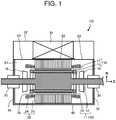
- FIG. 1 is an elevation sectional view illustrating the configuration of a squirrel-cage induction rotating electrical machine according to an embodiment.
- a squirrel-cage induction rotating electrical machine 100 includes a solid rotor 10, a stator 20, bearings 30, a frame 40, and a cooler 51.
- the solid rotor 10 is a solid magnetic pole type rotor integrally having a rotor core and a rotor shaft for securing its mechanical strength and includes an integral rotor 11, a plurality of conductor bars 16, and two short-circuit rings 17.
- the integral rotor 11 is a rotationally symmetric body and has a shape combining columns having different diameters along the rotation axis direction, which is hereinafter also expressed simply by the term "axial direction”, “axial”, or “axially”.
- a larger-diameter column at the axial center part of the integral rotor 11 constitutes a rotor core part 13.
- a smaller-diameter part at each axial side of the rotor core part 13 constitutes a shaft part 12.
- the shaft part 12 is rotatably supported at both axial sides by the bearings 30.
- Internal fans 18 are attached to the shaft part 12 at positions between the rotor core part 13 and the two bearings 30.
- the plurality of conductor bars 16 axially extend through the vicinity of the radial surface of the rotor core part 13, as described later.
- the conductor bars 16 axially protrude from both sides of the rotor core part 13 by the same length.
- Each of the end portions of each conductor bar 16 are electrically and mechanically coupled to the short-circuit ring 17 provided at each axially outer sides from the rotor core part 13, whereby the plurality of conductor bars 16 are mutually electrically coupled.
- the conductor bar 16 and short-circuit ring 17 are each made of a material having a conductivity higher than that of the rotor core part 13.
- the rotor core part 13 is made of, for example, steel or low-alloy steel, while the conductor bar 16 and short-circuit ring 17 are each made of, for example, copper or aluminum.
- the stator 20 includes a stator core 21 and a plurality of stator windings 24.
- the stator core 21 is disposed radially outside the rotor core part 13 of the solid rotor 10 via a annular gap 25 therebetween.
- the stator core 21 has a hollow cylindrical shape, and the stator windings 24 penetrate the vicinity of the inner surface of the stator core 21.
- the frame 40 houses the stator 20 and the rotor core part 13.
- Bearing brackets 35 are fixed at both axial ends of the frame 40. Each of the bearing brackets 35 stationarily support each corresponding bearing 30.
- the cooler 51 is disposed above the frame 40 and is surrounded by a cooler cover 52.
- the cooler cover 52 forms a closed space 61 together with the frame 40 and the two bearing brackets 35.
- the closed space 61 is filled with cooling gas, such as air, which is driven by the internal fan 18 to circulate in the closed space 61.
- a space within the cooler cover 52 and a space within the frame 40, which form the closed space 61, communicate with each other through a cooler inlet opening 62 formed above the stator 20 and each cooler outlet opening 63 formed above each internal fan 18.
- FIG. 2 is a cross-sectional view illustrating a solid rotor and stator slots of the squirrel-cage induction rotating electrical machine according to the embodiment.
- a plurality of groove-like rotor slots 14 each having a width d are formed in the surface of the rotor core part 13 so as to be disposed with circumferential intervals therebetween and to extend axially.
- the conductor bar 16 passes through each rotor slot 14.
- the rotor slot 14 has an outer wall 14a, an inner wall 14b, and a radially innermost wall 14c which axially extend.
- the outer wall 14a and the inner wall 14b are formed in parallel to each other.
- the innermost wall 14c has a curved shape in cross section of the rotor slot 14.
- the rotor slot 14 radially extends to the depth of an inscribed circle 14d.
- the conductor bar 16 and the rotor slot 14 have substantially the same shape and cross-sectional dimensions.
- the conductor bar 16 has a flat-plate shape elongating axially.
- the conductor bar 16 can be fitted into the rotor slot 14 from radially outside the rotor slot 14.
- a silver brazing foil may be wound around the conductor bar 16 so as to cover its parts opposite to the outer wall 14a, inner wall 14b, and innermost wall 14c, and then the resultant conductor bar 16 is inserted into the rotor slot 14, followed by melting of the silver brazing foil.
- TIG welding may be applied from outside after the conductor bar 16 is inserted into the rotor slot 14, or the conductor bar 16 that has been inserted into the rotor slot 14 and the rotor slot 14 may be brought into pressure contact with each other.
- the radially outer end portion of the conductor bar 16 is flush with the radially outer surface of the rotor core part 13 forming a cylindrical shape.
- the radially outer end portion of the conductor bar 16 may be partially retracted radially inward from the surface of the cylinder by, for example, forming the radially outer end portion of the conductor bar 16 perpendicular to the flat surface of the outer and inner walls 14a and 14b.
- the conductor bar 16 is fitted into the rotor slot 14 from radially outside the rotor slot 14 ; however, the conductor bar 16 may be inserted from an axially end portion of the rotor core part 13.
- the conductor bar 16 can be formed in a shape other than the flat-plate shape. For example, a maximum thickness portion or a minimum thickness portion may be formed in the axially middle portion of the conductor bar 16 so as to resist the centrifugal force.
- the rotor slot 14 does not extend along the radial direction from the rotation center but is circumferentially tilted with respect to the radial direction. This will be described in detail later using FIG. 10 . Since the rotor slots 14 are thus formed, rotor teeth 15 as many as the number of the rotor slots 14 are formed so as to be disposed with circumferential intervals therebetween.
- a plurality of groove-like stator slots 22 are formed so as to be disposed with circumferential intervals and to extend axially in radially inner surface of the stator core 21 disposed radially outside the rotor core part 13 via the gap 25.
- stator teeth 23 as many as the number of the stator slots 22 are provided so as to be circumferentially spaced from one another.
- the direction of the stator teeth 23 is defined such that the center plane between opposing side walls of each stator slot 22 passes the center axis of the solid rotor 10.
- a stator winding conductor 24a passes through each stator slot 22 to constitute the stator winding 24.
- the circumferential tilt angle ⁇ of the rotor slot 14 is defined, in the cross section perpendicular to the axial direction illustrated in FIG. 2 , as an angle formed by a line connecting an point PP1, which is an intersection between the widthwise center line of the rotor slot 14 and the circumscribed circle of the solid rotor 10, and a rotation center axis 11a of the rotor core part 13, and the widthwise center line of the rotor slot 14.
- that angle ⁇ is set to zero, while in the present embodiment, the angle ⁇ is set to a value larger than 0. That is, the rotor slot 14 is tilted with respect to the line connecting the intersection point PP1 and the rotation center axis 11a.
- the arrangement pitch of the rotor slots 14 can be defined in various ways. Specifically, as illustrated in FIG. 2 , the cross section perpendicular to the axial direction, the arrangement pitch may be defined by a circumferential angle interval ⁇ r formed by points PP1 and PP2 on the solid rotor 10 or by an interval ⁇ Pr between the points PP1 and PP2. Further, although not illustrated, the arrangement pitch may be defined by an interval between the points PP1 and PP2 on the circumference of the circumscribed circle of the rotor core part 13.
- the circumferential angle interval ⁇ r and interval ⁇ Pr defining the arrangement pitch of the rotor slots 14 one-to-one correspond to each other and, further, they also one-to-one correspond to the number of the rotor slots.
- the arrangement pitch of the stator slots 22 may be defined by a circumferential angle interval ⁇ s or by an interval ⁇ Ps, as illustrated in FIG. 2 .
- the circumferential angle interval ⁇ s and the interval ⁇ Ps one-to-one correspond to each other and, further, they also one-to-one correspond to the number of the stator slots.
- the arrangement pitch of the rotor slots 14 or arrangement pitch of the stator slot 22 is assumed to be determined by any of the above definitions.
- FIG. 3 is a flowchart illustrating the procedure of a design method for the solid rotor of the squirrel-cage induction rotating electrical machine according to the embodiment. More specifically, the flowchart of FIG. 3 illustrates the procedure of a design method for determining an optimum range of the circumferential tilt angle ⁇ (hereinafter, referred to as "rotor slot tilt angle ⁇ ") of the rotor slot 14.
- rotor slot tilt angle ⁇ the procedure of a design method for determining an optimum range of the circumferential tilt angle ⁇ (hereinafter, referred to as "rotor slot tilt angle ⁇ ") of the rotor slot 14.
- design conditions for the stator slots 22 e.g., dimensions and circumferential arrangement pitch of the stator slots 22
- the dimension of the stator winding conductor 24a passing through each stator slot 22 is set in accordance with the set design conditions for the stator slots 22.
- design conditions for the rotor slots 14 e.g., dimensions and circumferential arrangement pitch of the rotor slots 14
- step S03 the rotor slot tilt angle ⁇ is set (step S03).
- the dimensions and shape of the conductor bar 16 passing through each rotor slot 14 are set in accordance with the set design conditions for the rotor slots 14.
- Design conditions other than those for the rotor slots 14 and the stator slots 22, such as the dimensions of the solid rotor 10, the stator 20, and the gap 25, are assumed to be preset.
- a loss in the rotor core part 13 of the solid rotor 10 is calculated (step S04). Subsequently, temperature distribution in the rotor core part 13 is calculated based on the determined loss (step S05).
- stress distribution in the rotor core part 13 is calculated in parallel with the temperature calculation in steps S04 and S05 (step S06).
- step S07 it is determined whether the procedure up to step S06 is completed over the entire examination target range of the rotor slot tilt angle ⁇ (step S07).
- the examination target range of the rotor slot tilt angle ⁇ is from ⁇ smin to ⁇ smax
- ⁇ smin is an angle larger than 0°
- ⁇ smax is an angle smaller than 90°.
- the examination target range may be wide to some extent (e.g., in a range from 10° to 80°) or may be narrower.
- step S07 When the determination in step S07 is NO, the procedure returns to step S03, and the procedure up to step S06 is performed after changing the rotor slot tilt angle ⁇ to another value.
- step S07 determines whether the procedure up to step S06 is completed over the entire examination target range of the arrangement pitch of the rotor slots 14 (step S08).
- step S08 determines whether the procedure up to step S06 is completed over the entire examination target range of the arrangement pitch of the rotor slots 14 (step S08).
- step S08 determines whether the determination in step S08 is YES. If the determination in step S08 is YES, the procedure proceeds to step S10.
- An evaluation function is determined before step S10 (step S09).
- the evaluation function is, for example, an evaluation function PI(n) represented by the following equations (2) and (3) for minimizing overall generated stress and loss regarding the number n of the rotor slots, or an evaluation function PI( ⁇ ,n 0 ) represented by the following equation (4) for minimizing overall generated stress and loss.
- step S10 the number n of the rotor slots 14 and rotor slot tilt angle ⁇ are determined based on the evaluation function set in step S09 (step S10).
- step S02 to step S08 is a survey performed for a predetermined examination target range of the rotor slot tilt angle ⁇ and a predetermined examination target range of the arrangement pitch of the rotor slots 14 or of the number n of the rotor slots corresponding to the arrangement pitch.
- the number n of the rotor slots 14 and rotor slot tilt angle ⁇ are determined in step S09 and step S10 based on results of the survey. The following describes the processing in step S09 and step S10.
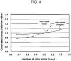
- FIG. 4 is a graph illustrating an example of estimation of the relationship between the number of the rotor slots and a generated stress in the solid rotor of the squirrel-cage induction rotating electrical machine according to the embodiment.
- the horizontal axis represents the ratio of the number n of the rotor slots to the reference number n 0 of the rotor slots.
- the vertical axis represents the ratio (relative value) of a generated stress to that when the number of the rotor slots is the reference number n 0 .
- the dashed curve in the graph represents a case where a slot width d of the rotor slot 14 is changed in an inverse proportion to the number of rotor slots 14.
- the dashed double-dotted curve represents a case where the slot width d of the rotor slot 14 is fixed.
- the generated stress in this estimation is measured at the root of the rotor teeth 15, where it exhibits the maximum value in stress distribution.
- an increase in the number of the rotor slots 14 increases the stress. This is so even when the slot width d is reduced in accordance with the increase in the number of the rotor slots 14, although the degree of increase in the stress is reduced.
- FIG. 5 is a graph illustrating an example of estimation of the relationship between the number of the rotor slots and a loss in the solid rotor of the squirrel-cage induction rotating electrical machine according to the embodiment.
- the horizontal axis represents the ratio of the number n of the rotor slots to the reference number n 0 of the rotor slots.
- the vertical axis represents the ratio (relative value) of a loss to that when the number of the rotor slots is the reference number n 0 .
- FIG. 6 is a first conceptual partial cross-sectional view of the relationship between the stator and the rotor slots of the squirrel-cage induction rotating electrical machine according to the embodiment
- FIGS. 7 and 8 are respectively second and third conceptual partial cross-sectional views thereof.
- the stator winding conductor 24a FIG. 2
- the dashed curve in each graph conceptually represents circumferential flux density distribution by the stator windings 24 ( FIG. 1 ) at a certain moment.
- the number of the rotor slots 14 is assumed to be n, and the number of the stator slots 22 is N.
- FIG. 6 illustrates a case where n is equal to N.
- the circumferential flux density distribution formed by current flowing through the stator winding 24 has a pitch, i.e., period of a phase corresponding to the distribution of the positions of the stator slots 22.
- the second conceptual view of FIG. 7 illustrates a case where the number n of the rotor slots is larger than the number N of the stator slots.
- the arrangement pitch of the rotor slots 14 differs from the period, i.e., phase pitch of the circumferential flux density distribution formed by current flowing through the stator winding 24. Therefore, the magnetic flux penetrates the conductor bars 16 without fail. In this case, a part of the magnetic flux penetrates any of the conductor bars 16. A part of the magnetic flux that does not penetrate the conductor bars 16 becomes leakage magnetic flux.
- the third conceptual view of FIG. 8 illustrates a case where the number n of the rotor slots is further increased to be twice the number N of the stator slots.
- the magnetic flux penetrates any of the conductor bars 16 at any phase, and the amount of leakage magnetic flux is smaller than that in the cases of the first and second conceptual views, thus minimizing a magnetic loss.
- the magnetic flux generated by the stator winding 24 ( FIG. 1 ) and the conductor bars 16 of the solid rotor 10 may be coupled to each other more strongly. This is a factor that reduces the loss.
- the number n of the rotor slots is preferably larger than the number N of the stator slots. Specifically, establishing the following equation (1) is required. n / N ⁇ 1.1
- FIG. 9 is a graph illustrating an example of estimation of the relationship between the number of the rotor slots and the loss in the solid rotor of the squirrel-cage induction rotating electrical machine according to the embodiment. That is, FIG. 9 combines the graphs of FIGS. 4 and 5 into one graph.
- the horizontal axis represents the ratio of the number n of the rotor slots to the reference number n 0 of the rotor slots.
- the vertical axis represents the ratio (relative value) of the generated stress to that when the number of the rotor slots is the reference number n 0 of the rotor slots and the ratio (relative value) of the loss to that when the number of the rotor slots is the reference number n 0 .
- the solid curve represents the loss
- the dashed curve represents the generated loss obtained under a condition where the slot width is changed (reduced)
- dashed double-dotted curve represents the generated stress obtained under a condition where the slot width is fixed.
- the generated stress tends to increase, whereas the loss tends to decrease. That is, the generated stress and the loss exhibit reverse increase/decrease tendency with respect to the increase in the number of rotor slots 14.
- the generated stress and the generated loss are mutually different characteristic values, they are common in being a drawback factor.
- the two drawback factors are evaluated according to a common criterion, and a negative drawback is minimized as a whole.
- the generated stress and the generated loss when the number of the rotor slots is n 0 are assumed to be S 0 and L 0 , respectively.
- the n 0 may have any value.
- the generated stress and the generated loss in the case that the number of the rotor slots is n are assumed to be S(n) and L(n), respectively.
- PIn(n) represented by the following equation (2) for n, it is possible to determine the number of the rotor slots that minimizes the generated stress and the generated loss as a whole.
- PIn n S n / S 0 + p ⁇ L n / L 0
- the first evaluation function PIn(n) may be represented by the following equation (3).
- PIn n S n / S 0 ⁇ L n / L 0 p
- S 0 and L 0 each are any reference value.
- the constant p is a value for reflecting the weights of both disadvantages brought about by the generated stress S(n) and by the generated loss L(n) and is set considering, for example, the use purpose of a target rotating electrical machine or a design margin.
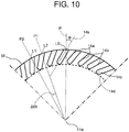
- FIG. 10 is a partial cross-sectional view for explaining the rotor slot tilt angle of the solid rotor according to the embodiment.
- a virtual plane 14s positioned at the center between the outer wall 14a and the inner wall 14b, which are mutually opposing and mutually parallel, of one rotor slot 14.
- the radial surface of the rotor core part 13 is defined as a curved surface Sf.
- the intersection line between the curved surface Sf and the virtual plane 14s is defined as an intersection line L0.
- the plane passing the rotation center axis 11a and intersection line L0 is defined as a plane P.
- the two planes i.e., the virtual plane 14s and the plane P pass the intersection line L0.
- the circumferential intersection angle formed by the two planes is defined as the rotor slot tilt angle ⁇ (0° ⁇ rotor slot tilt angle ⁇ ⁇ 90°).
- the angle formed by planes P1 and P2 passing through adjacent intersection lines L1 and L2, respectively, is defined as a pitch angle ⁇ r (0° ⁇ pitch angle ⁇ r ⁇ 90°).
- FIG. 11 is a cross-sectional view illustrating the solid rotor and stator slots when the rotor slot tilt angle of the solid rotor according to the embodiment is zero. That is, FIG. 11 illustrates a conventionally configured rotor slots 74.
- the center plane between two mutually parallel opposing walls 74a of the rotor slot 74 passes the rotation center axis 11a, and an innermost part 74c is positioned closer to the rotation center axis 11a (i.e., formed deeper) than in the present embodiment.
- the virtual plane 14s and the plane P which cross each other in the configuration illustrated in FIG. 10 , coincide with each other in the configuration of FIG. 11 and, in this case, the rotor slot tilt angle ⁇ defined in a similar manner as in FIG. 10 is 0°.
- the rotor slot 14 formed in the surface of the rotor core part 13 of the solid rotor 10 is circumferentially tilted. Further, the ratio of the number of the rotor slots 14 to the number of the stator slots 22 is larger than 1.1.
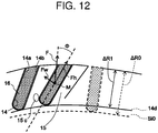
- FIG. 12 is a conceptual partial cross-sectional view for explaining the effect of the solid rotor of the squirrel-cage induction rotating electrical machine according to the embodiment.
- the two left side rotor slots in the drawing are the rotor slots 14 of the rotor core part 13 according to the present embodiment and the conductor bars 16 passing therethrough.
- a conventional rotor slot and a conductor bar having the same cross-sectional area as that of the conductor bar according to the present embodiment are denoted by the thick and thin dashed lines, respectively.
- the radius of the inscribed circle 14d of the rotor slots 14 in the present embodiment is larger than the radius of an inscribed circle Si0 of the conventional rotor slots. That is, a radial width ⁇ R1 of the rotor slot 14 according to the present embodiment is smaller than a radial width ⁇ R0 of the conventional rotor slot.
- ⁇ R1 is substantially ⁇ R0.cos ⁇ .
- An iron loss is typically generated in the rotor core part 13 having a lower conductivity than that of the conductor bar 16, and an induced current flows mainly on the surface of the rotor core part 13, so that the surface temperature of the rotor core part 13 tends to increase.
- the relative reduction in the distance between the overall position of the conductor bar 16 and the stator windings 24 increases the coupling strength therebetween due to magnetic flux penetrating the stator core 21 and conductor bars 16, leading to improvement in efficiency. As a result, the loss is reduced.
- an increase in a surface temperature Ts of the rotor core part 13 according to the present embodiment is suppressed more than conventional type.
- the ratio of the radial width of the rotor slots 14 it is considered necessary to reduce the ratio of the radial width of the rotor slots 14 by, for example, at least about 5% to 10%, although evaluation needs to be performed including the stator windings 24.
- the value of cos ⁇ is 0.9 to 0.95; that is, ⁇ is 18° to 26°.
- the rotor slot tilt angle ⁇ needs to be at least about 20°.
- a centrifugal force F at a barycenter M in the cross section of the conductor bar 16 is resolved into a component force Fh withdrawing the conductor bar 16 along the rotor slot 14 and a component force Fw being perpendicular to the component force Fh and acting on the outer wall 14a of the rotor slot 14.
- the value of the component force Fh is F cos ⁇ , which is smaller than the value of the centrifugal force F.
- F - F cos ⁇ serves as a margin for a coming-off prevention measure equivalent to that conventionally taken.
- a margin equivalent to that conventionally ensured is available in a coming-off measure such as brazing that does not require large-scale facilities as much as conventional measures such as pressing.
- the value of the component force Fw acting on the outer wall 14a is F sin ⁇ , which bends the rotor teeth 15 in the circumferential direction so as to make the rotor teeth along the radial direction.
- F sin ⁇ the value of the component force Fw acting on the outer wall 14a
- a maximum stress value Smax occurs at a root 15c of the rotor teeth 15.
- the rotor slot tilt angle is set such that the maximum stress value Smax falls within a value range sufficiently smaller than allowable stress.
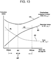
- FIG. 13 is a conceptual graph for explaining the effect of the solid rotor of the squirrel-cage induction rotating electrical machine according to the embodiment, and this graph further explains procedures for creating an allowance map and determining a rotor slot tilt angle and a rotor slot arrangement pitch in the design method for the squirrel-cage induction rotating electrical machine.
- the horizontal axis represents the rotor slot tilt angle ⁇ .
- the vertical axis represents evaluation values of the loss L( ⁇ , n 0 ) denoted by curve A0, the evaluation values of the generated stress S( ⁇ , n 0 ) denoted by curve B0, and function values of a disadvantage evaluation function PI ⁇ ( ⁇ , n 0 ) denoted by curve C0 combining the loss L( ⁇ , n 0 ) and generated stress S ( ⁇ , n 0 ).
- the generated stress S( ⁇ , n 0 ) and loss L( ⁇ , n 0 ) are values corresponding to the rotor slot tilt angle ⁇ when the number of rotor slots is n 0 .
- PI ⁇ ( ⁇ , n 0 ) is represented by the following equation (4).
- PI ⁇ ⁇ n 0 g S ⁇ n 0 , L ⁇ n 0
- n 0 is a value in the range of the numbers n of the rotor slots determined in the first step, i.e., the minimizing step (e.g., equation (2) or (3)) for the number n of the rotor slots and is used as a parameter. That is, in the present second step, i.e., a disadvantage evaluation function minimizing step with respect to the rotor slot tilt angle ⁇ , n 0 is used as a constant value.
- a combination that minimizes the value of the disadvantage evaluation function PI ⁇ ( ⁇ , n 0 ) includes the (number n of the rotor slots) and (rotor slot tilt angle ⁇ ) to be finally determined.
- the disadvantage evaluation function PI ⁇ ( ⁇ , n 0 ) may be represented by the following equation (5).
- PI ⁇ ⁇ n 0 S ⁇ n 0 / S 0 + q ⁇ L ⁇ n 0 / L 0
- the evaluation function PI (n) may be represented by the following equation (6).
- PI ⁇ ⁇ n 0 S ⁇ n 0 / S 0 ⁇ L ⁇ n 0 / L 0 q
- the constant q is a value for reflecting the weights of both disadvantages brought about by the generated stress S(n) and the generated loss L(n), like the constant p in the first step, and is set considering, for example, the use purpose of a target rotating electrical machine or a design margin.
- equations (2) and (3) in the first step and equations (5) and (6) in the second step are illustrative and not restrictive. That is, when there is any other index that is subjected to the influence of the rotor slot tilt angle ⁇ , it may be added as a variable to the above-described equations. Further, when influence on a given index is negligible, this index may be excluded from the equation (1). Further, a function different from that described above may be used.
- an upper limit value HL is provided for the value of the loss L( ⁇ , n 0 ) to restrict a range of the rotor slot tilt angle ⁇ such that ⁇ > ⁇ 0min ( ⁇ 0min is a value corresponding to the upper limit value HL) is satisfied.
- the upper limit value HL is set to, for example, a value of the loss L that provides a maximum temperature obtained by subtracting a predetermined margin from the upper limit of a temperature range in which operation of the rotor core part 13 can be maintained.
- an upper limit value HS is provided for the value of the generated stress S( ⁇ , n 0 ) to restrict a range of the rotor slot tilt angle ⁇ such that ⁇ ⁇ ⁇ 0max ( ⁇ 0max is a value corresponding to the upper limit value HS).
- the upper limit value HS is set to, for example, a value of the generated stress S obtained by subtracting a predetermined margin from an allowable stress for the material of the rotor core part 13.
- a value of the rotor slot tilt angle ⁇ that provides the minimum value is determined. Then, a predetermined angle range ⁇ is given to the determined minimum value, and the range from ( ⁇ 0 - ⁇ ) to ( ⁇ 0 + ⁇ ) is determined as an optimum range.
- the angle range ⁇ may be set to about 5° to about 10° which is sufficiently larger than the manufacturing accuracy of the squirrel-cage induction rotating electrical machine 100 including formation of the rotor slot 14.
- the solid rotor 10 by circumferentially tilting the rotor slot 14, it is possible to suppress an increase in the surface temperature Ts of the rotor core part 13 while relaxing the condition concerning the coming-off of the conductor bar 16 from the rotor slot 14. Further, efficiency is further improved by making the number of the rotor slots 14 larger than a value 1.1 times the number of the stator slots 22. Thus, an increase in the surface temperature Ts of the rotor core part 13 can be further suppressed.
- the number n of the rotor slots 14 and the tilt angle ⁇ of the rotor slot 14 can be optimally set based on the indices such as the generated stress S( ⁇ , n 0 ) and the generated loss L ( ⁇ , n 0 ).
- the conductor bars 16 are reliably prevented from coming off radially outward, and an increase in the surface temperature Ts of the rotor core part 13 is suppressed.
Landscapes
- Engineering & Computer Science (AREA)
- Power Engineering (AREA)
- Manufacturing & Machinery (AREA)
- Induction Machinery (AREA)
- Iron Core Of Rotating Electric Machines (AREA)
Abstract
Description
- The present invention relates to a squirrel-cage induction rotating electrical machine, a solid rotor, and a design method for a squirrel-cage induction rotating electrical machine.
- An induction rotating electrical machine has an advantage of having a simpler structure compared to a synchronous rotating electrical machine, although having limitations such as inability of making power factor adjustment as the synchronous rotating electrical machine does. The induction rotating electrical machine is typically classified into a winding induction rotating electrical machine and a squirrel-cage induction rotating electrical machine. The squirrel-cage induction rotating electrical machine does not require electrical connection to an external device unlike the winding induction rotating electrical machine and has a simpler structure than the winding induction rotating electrical machine. In particular, the squirrel-cage induction rotating electrical machine can be easily controlled from a power source side due to improvement in performance of a power semiconductor, and thus a system combining the squirrel-cage induction rotating electrical machine and power semiconductor is widely used.
- In the squirrel-cage induction rotating electrical machine, a plurality of rotor slots are formed in the vicinity of the radial surface of the rotor core so as to be disposed with circumferential intervals therebetween and to axially penetrate the rotor core. Conductor bars pass through the respective rotor slots and are electrically coupled together by a short-circuit ring disposed at axially outside the rotor core. The rotor slots are formed so as to extend from the surface of the rotor core toward the rotation center axis thereof and each have a cross-sectional shape close to, for example, a rectangle (Refer to Patent Document 1) or an oval (Refer to Patent Document 2).
- In some cases, the conductor bars and the short-circuit ring are integrally formed of aluminum by casting (Refer to Patent Document 3).
-
- Patent Document 1: Japanese Patent Application Laid-Open Publication No.
2016-220404 - Patent Document 2: Japanese Patent No.
3752781 - Patent Document 3: Japanese Patent Application Laid-Open Publication No.
2014-195374 - Patent Document 4: Japanese Patent No.
5557685 - Patent Document 5:
U.S. Patent No. 6933647 - A rotor is typically composed of a rotor shaft and a rotor core formed by laminated plates that is attached to radially outside the rotor shaft. In this configuration, the laminated plates are electrically insulated from one another, so that axial eddy current does not occur. In the squirrel-cage induction rotating electrical machine having a rotor core formed by laminated plates, heat generation at the conductor bars of the rotor is suppressed to reduce heat generation across the rotor (Refer to Patent Document 4).
- A high-speed machine operating at a high speed sometimes employs a solid magnetic pole type rotor (solid rotor) integrally having a rotor core and a rotor shaft for the purpose of enhancing its mechanical strength. In such high speed, an increased centrifugal force acts on the conductor bars, so that it is necessary to reliably prevent the conductor bars from coming off radially outward. The direction of the centrifugal force coincides with a direction in which each slot extends, so that, for example, the conductor bars are each brought into pressure contact with the rotor core for the prevention of coming-off (Refer to Patent Document 5).
- The solid rotor has a simpler structure than a rotor having a laminated structure and is thus excellent in mechanical strength; however, axial eddy current occurs in the solid rotor, producing a larger loss than the rotor having a laminated structure. This disadvantageously increases the temperature of the surface of the rotor core.
- An object of the present invention is therefore to secure preventing the conductor bars from coming off radially outward and to suppress surface temperature rise in the squirrel-cage induction rotating electrical machine having a solid rotor.
- According to the present invention, there is provided a squirrel-cage induction rotating electrical machine comprising: a solid rotor extending axially and supported rotatably, including a shaft part and a columnar-shaped rotor core part integrally formed with the shaft part, the columnar-shaped rotor core part having a diameter larger than that of the shaft part and having rotor slots formed therein which are disposed with circumferential intervals therebetween and extend axially, and a plurality of conductor bars passing through the respective rotor slots and coupled together at both axial ends outside the rotor core part; a stator having a cylindrical stator core provided radially outside the rotor core part and stator windings passing through a plurality of respective stator slots which are formed in the radially inner surface of the stator core so as to be disposed with circumferential intervals therebetween and to extend axially; and two bearings supporting the solid rotor at both axial sides of the shaft part, sandwiching the rotor core part, wherein two opposing walls of each rotor slot are circumferentially tilted at a predetermined angle or more with respect to a plane including a rotation axis of the shaft part.
- According to the present invention, there is provided a solid rotor used for a squirrel-cage induction rotating electrical machine, comprising: a shaft part extending axially and supported rotatably; a columnar-shaped rotor core part integrally formed with the shaft part, having a diameter larger than that of the shaft part, and having formed therein rotor slots which are disposed with circumferential intervals therebetween and extend axially; and a plurality of conductor bars passing through the respective rotor slots and coupled together at both ends outside the rotor core part, wherein two opposing walls of each rotor slot are circumferentially tilted at a predetermined angle or more with respect to a plane including a rotational axis of the shaft part.
- According to the present invention, there is provided a design method for a squirrel-cage induction rotating electrical machine provided with a solid rotor having a shaft part and a rotor core part which are integrally formed and a stator provided radially outside the rotor core part, comprising: a stator condition setting step of setting dimensions and arrangement pitch of a plurality of stator slots which are formed in the radially inner surface of the stator so as to be disposed with circumferential intervals therebetween and to extend axially; a rotor condition setting step of setting, after the stator condition setting step, dimensions and arrangement pitch of rotor slots which are formed in the radially outer surface of the rotor core part so as to be disposed with circumferential intervals therebetween and to penetrate axially the rotor core part; a tilt angle setting step of setting a circumferential tilt angle of the rotor slot after the rotor condition setting step; a stress calculation step of calculating stress of the rotor core part after the tilt angle setting step; a temperature calculation step of calculating temperature of the rotor core part after the tilt angle setting step; an angle range determination step of determining whether processing for examining the circumferential tilt angle of the rotor slot is completed over the entire examination target range and performing the tilt angle setting step and subsequent steps when the determination is negative; a pitch range determination step of determining whether processing for examining the arrangement pitch of the rotor slots is completed over the entire examination target range when the determination in the angle range determination step is positive and performing the rotor condition setting step and subsequent steps when the determination in this pitch range determination step is negative; and a determination step of determining the tilt angle and pitch of the rotor slots based on results of the stress calculation step and temperature calculation step when the determination in the pitch range determination step is positive.
- According to the present invention, it is possible to secure preventing the conductor bars from coming off radially outward and to suppress surface temperature rise in the squirrel-cage induction rotating electrical machine having a solid rotor.
-
-
FIG. 1 is an elevation sectional view illustrating the configuration of a squirrel-cage induction rotating electrical machine according to an embodiment. -
FIG. 2 is a cross-sectional view illustrating a solid rotor and stator slots of the squirrel-cage induction rotating electrical machine according to the embodiment. -
FIG. 3 is a flowchart illustrating the procedure of a design method for the solid rotor of the squirrel-cage induction rotating electrical machine according to the embodiment. -
FIG. 4 is a graph illustrating an example of estimation of the relationship between the number of the rotor slots and a generated stress in the solid rotor of the squirrel-cage induction rotating electrical machine according to the embodiment. -
FIG. 5 is a graph illustrating an example of estimation of the relationship between the number of the rotor slots and a loss in the solid rotor of the squirrel-cage induction rotating electrical machine according to the embodiment. -
FIG. 6 is a first conceptual partial cross-sectional view of the relationship between the stator and the rotor slots of the squirrel-cage induction rotating electrical machine according to the embodiment. -
FIG. 7 is a second conceptual partial cross-sectional view of the relationship between the stator and the rotor slots of the squirrel-cage induction rotating electrical machine according to the embodiment. -
FIG. 8 is a third conceptual partial cross-sectional view of the relationship between the stator and the rotor slots of the squirrel-cage induction rotating electrical machine according to the embodiment. -
FIG. 9 is a graph illustrating an example of estimation of the relationship between the number of the rotor slots and the loss in the solid rotor of the squirrel-cage induction rotating electrical machine according to the embodiment. -
FIG. 10 is a partial cross-sectional view for explaining the rotor slot tilt angle of the solid rotor according to the embodiment. -
FIG. 11 is a cross-sectional view illustrating the solid rotor and stator slots when the rotor slot tilt angle of the solid rotor according to the embodiment is zero. -
FIG. 12 is a conceptual partial cross-sectional view for explaining the effect of the solid rotor of the squirrel-cage induction rotating electrical machine according to the embodiment. -
FIG. 13 is a conceptual graph for explaining the effect of the solid rotor of the squirrel-cage induction rotating electrical machine according to the embodiment, and further for explaining procedures for creating an allowance map and determining a rotor slot tilt angle and a rotor slot arrangement pitch in the design method for the squirrel-cage induction rotating electrical machine. - Embodiments of a squirrel-cage induction rotating electrical machine, a solid rotor, and a design method for a squirrel-cage induction rotating electrical machine according to the present invention will be described with reference to the drawings. Throughout the description, the same reference numerals are given to the same or similar parts, and repeated description will be omitted.
-
FIG. 1 is an elevation sectional view illustrating the configuration of a squirrel-cage induction rotating electrical machine according to an embodiment. - A squirrel-cage induction rotating
electrical machine 100 includes asolid rotor 10, astator 20,bearings 30, aframe 40, and acooler 51. - The
solid rotor 10 is a solid magnetic pole type rotor integrally having a rotor core and a rotor shaft for securing its mechanical strength and includes anintegral rotor 11, a plurality ofconductor bars 16, and two short-circuit rings 17. - The
integral rotor 11 is a rotationally symmetric body and has a shape combining columns having different diameters along the rotation axis direction, which is hereinafter also expressed simply by the term "axial direction", "axial", or "axially". A larger-diameter column at the axial center part of theintegral rotor 11 constitutes arotor core part 13. A smaller-diameter part at each axial side of therotor core part 13 constitutes ashaft part 12. Theshaft part 12 is rotatably supported at both axial sides by thebearings 30.Internal fans 18 are attached to theshaft part 12 at positions between therotor core part 13 and the twobearings 30. - The plurality of
conductor bars 16 axially extend through the vicinity of the radial surface of therotor core part 13, as described later. The conductor bars 16 axially protrude from both sides of therotor core part 13 by the same length. Each of the end portions of eachconductor bar 16 are electrically and mechanically coupled to the short-circuit ring 17 provided at each axially outer sides from therotor core part 13, whereby the plurality ofconductor bars 16 are mutually electrically coupled. Theconductor bar 16 and short-circuit ring 17 are each made of a material having a conductivity higher than that of therotor core part 13. For example, therotor core part 13 is made of, for example, steel or low-alloy steel, while theconductor bar 16 and short-circuit ring 17 are each made of, for example, copper or aluminum. - The
stator 20 includes astator core 21 and a plurality ofstator windings 24. Thestator core 21 is disposed radially outside therotor core part 13 of thesolid rotor 10 via aannular gap 25 therebetween. Thestator core 21 has a hollow cylindrical shape, and thestator windings 24 penetrate the vicinity of the inner surface of thestator core 21. - The
frame 40 houses thestator 20 and therotor core part 13.Bearing brackets 35 are fixed at both axial ends of theframe 40. Each of the bearingbrackets 35 stationarily support each correspondingbearing 30. - The cooler 51 is disposed above the
frame 40 and is surrounded by acooler cover 52. Thecooler cover 52 forms aclosed space 61 together with theframe 40 and the two bearingbrackets 35. Theclosed space 61 is filled with cooling gas, such as air, which is driven by theinternal fan 18 to circulate in the closedspace 61. A space within thecooler cover 52 and a space within theframe 40, which form the closedspace 61, communicate with each other through a cooler inlet opening 62 formed above thestator 20 and each cooler outlet opening 63 formed above eachinternal fan 18. -
FIG. 2 is a cross-sectional view illustrating a solid rotor and stator slots of the squirrel-cage induction rotating electrical machine according to the embodiment. - A plurality of groove-
like rotor slots 14 each having a width d are formed in the surface of therotor core part 13 so as to be disposed with circumferential intervals therebetween and to extend axially. Theconductor bar 16 passes through eachrotor slot 14. Therotor slot 14 has anouter wall 14a, aninner wall 14b, and a radiallyinnermost wall 14c which axially extend. Theouter wall 14a and theinner wall 14b are formed in parallel to each other. Theinnermost wall 14c has a curved shape in cross section of therotor slot 14. Therotor slot 14 radially extends to the depth of an inscribedcircle 14d. - The
conductor bar 16 and therotor slot 14 have substantially the same shape and cross-sectional dimensions. Theconductor bar 16 has a flat-plate shape elongating axially. Theconductor bar 16 can be fitted into therotor slot 14 from radially outside therotor slot 14. To prevent theconductor bar 16 from coming off therotor slot 14, for example, a silver brazing foil may be wound around theconductor bar 16 so as to cover its parts opposite to theouter wall 14a,inner wall 14b, andinnermost wall 14c, and then theresultant conductor bar 16 is inserted into therotor slot 14, followed by melting of the silver brazing foil. Alternatively, TIG welding may be applied from outside after theconductor bar 16 is inserted into therotor slot 14, or theconductor bar 16 that has been inserted into therotor slot 14 and therotor slot 14 may be brought into pressure contact with each other. - The radially outer end portion of the
conductor bar 16 is flush with the radially outer surface of therotor core part 13 forming a cylindrical shape. Alternatively, the radially outer end portion of theconductor bar 16 may be partially retracted radially inward from the surface of the cylinder by, for example, forming the radially outer end portion of theconductor bar 16 perpendicular to the flat surface of the outer andinner walls - In the above description, the case in which the
conductor bar 16 is fitted into therotor slot 14 from radially outside therotor slot 14 is exemplified; however, theconductor bar 16 may be inserted from an axially end portion of therotor core part 13. In this case, theconductor bar 16 can be formed in a shape other than the flat-plate shape. For example, a maximum thickness portion or a minimum thickness portion may be formed in the axially middle portion of theconductor bar 16 so as to resist the centrifugal force. - The
rotor slot 14 does not extend along the radial direction from the rotation center but is circumferentially tilted with respect to the radial direction. This will be described in detail later usingFIG. 10 . Since therotor slots 14 are thus formed,rotor teeth 15 as many as the number of therotor slots 14 are formed so as to be disposed with circumferential intervals therebetween. - A plurality of groove-
like stator slots 22 are formed so as to be disposed with circumferential intervals and to extend axially in radially inner surface of thestator core 21 disposed radially outside therotor core part 13 via thegap 25. As a result,stator teeth 23 as many as the number of thestator slots 22 are provided so as to be circumferentially spaced from one another. The direction of thestator teeth 23 is defined such that the center plane between opposing side walls of eachstator slot 22 passes the center axis of thesolid rotor 10. Astator winding conductor 24a passes through eachstator slot 22 to constitute the stator winding 24. - Hereinafter, circumferential tilt angle Φ and arrangement pitch of the
rotor slots 14 and the arrangement pitch of thestator slots 22 will be described. - The circumferential tilt angle Φ of the
rotor slot 14 is defined, in the cross section perpendicular to the axial direction illustrated inFIG. 2 , as an angle formed by a line connecting an point PP1, which is an intersection between the widthwise center line of therotor slot 14 and the circumscribed circle of thesolid rotor 10, and arotation center axis 11a of therotor core part 13, and the widthwise center line of therotor slot 14. Conventionally, that angle Φ is set to zero, while in the present embodiment, the angle Φ is set to a value larger than 0. That is, therotor slot 14 is tilted with respect to the line connecting the intersection point PP1 and therotation center axis 11a. - The arrangement pitch of the
rotor slots 14 can be defined in various ways. Specifically, as illustrated inFIG. 2 , the cross section perpendicular to the axial direction, the arrangement pitch may be defined by a circumferential angle interval Δθr formed by points PP1 and PP2 on thesolid rotor 10 or by an interval ΔPr between the points PP1 and PP2. Further, although not illustrated, the arrangement pitch may be defined by an interval between the points PP1 and PP2 on the circumference of the circumscribed circle of therotor core part 13. When the diameter of therotor core part 13, i.e., the diameter of the circumscribed circle of therotor core part 13 is determined, the circumferential angle interval Δθr and interval ΔPr defining the arrangement pitch of therotor slots 14 one-to-one correspond to each other and, further, they also one-to-one correspond to the number of the rotor slots. - Similarly, the arrangement pitch of the
stator slots 22 may be defined by a circumferential angle interval Δθs or by an interval ΔPs, as illustrated inFIG. 2 . When the dimensions of thestator core 21 are determined, the circumferential angle interval Δθs and the interval ΔPs one-to-one correspond to each other and, further, they also one-to-one correspond to the number of the stator slots. - Hereinafter, the arrangement pitch of the
rotor slots 14 or arrangement pitch of thestator slot 22 is assumed to be determined by any of the above definitions. -
FIG. 3 is a flowchart illustrating the procedure of a design method for the solid rotor of the squirrel-cage induction rotating electrical machine according to the embodiment. More specifically, the flowchart ofFIG. 3 illustrates the procedure of a design method for determining an optimum range of the circumferential tilt angle Φ (hereinafter, referred to as "rotor slot tilt angle Φ") of therotor slot 14. - First, design conditions for the stator slots 22 (e.g., dimensions and circumferential arrangement pitch of the stator slots 22) are set (step S01). The dimension of the
stator winding conductor 24a passing through eachstator slot 22 is set in accordance with the set design conditions for thestator slots 22. - Then, design conditions for the rotor slots 14 (e.g., dimensions and circumferential arrangement pitch of the rotor slots 14) are set (step S02).
- Then, the rotor slot tilt angle Φ is set (step S03). The dimensions and shape of the
conductor bar 16 passing through eachrotor slot 14 are set in accordance with the set design conditions for therotor slots 14. - Design conditions other than those for the
rotor slots 14 and thestator slots 22, such as the dimensions of thesolid rotor 10, thestator 20, and thegap 25, are assumed to be preset. - After the design conditions for the
rotor slots 14 and thestator slots 22 are thus determined, a loss in therotor core part 13 of thesolid rotor 10 is calculated (step S04). Subsequently, temperature distribution in therotor core part 13 is calculated based on the determined loss (step S05). - Further, stress distribution in the
rotor core part 13 is calculated in parallel with the temperature calculation in steps S04 and S05 (step S06). - Then, it is determined whether the procedure up to step S06 is completed over the entire examination target range of the rotor slot tilt angle Φ (step S07). Assuming here that the examination target range of the rotor slot tilt angle Φ is from Φsmin to Φsmax, Φsmin is an angle larger than 0°, and Φsmax is an angle smaller than 90°. For example, the examination target range may be wide to some extent (e.g., in a range from 10° to 80°) or may be narrower.
- When the determination in step S07 is NO, the procedure returns to step S03, and the procedure up to step S06 is performed after changing the rotor slot tilt angle Φ to another value.
- When the determination in step S07 is YES, it is determined whether the procedure up to step S06 is completed over the entire examination target range of the arrangement pitch of the rotor slots 14 (step S08). When the determination in step S08 is NO, the procedure returns to step S02, and the procedure up to step S06 is performed after changing the arrangement pitch of the
rotor slot 14 to another value. - When the determination in step S08 is YES, the procedure proceeds to step S10.
- An evaluation function is determined before step S10 (step S09). The evaluation function is, for example, an evaluation function PI(n) represented by the following equations (2) and (3) for minimizing overall generated stress and loss regarding the number n of the rotor slots, or an evaluation function PI(Φ,n0) represented by the following equation (4) for minimizing overall generated stress and loss.
- Then, the number n of the
rotor slots 14 and rotor slot tilt angle Φ are determined based on the evaluation function set in step S09 (step S10). - While the procedure of the design method for the solid rotor illustrated in
FIG. 3 has been described briefly, the procedure in step S02 to step S08 is a survey performed for a predetermined examination target range of the rotor slot tilt angle Φ and a predetermined examination target range of the arrangement pitch of therotor slots 14 or of the number n of the rotor slots corresponding to the arrangement pitch. Actually, the number n of therotor slots 14 and rotor slot tilt angle Φ are determined in step S09 and step S10 based on results of the survey. The following describes the processing in step S09 and step S10. -
FIG. 4 is a graph illustrating an example of estimation of the relationship between the number of the rotor slots and a generated stress in the solid rotor of the squirrel-cage induction rotating electrical machine according to the embodiment. The horizontal axis represents the ratio of the number n of the rotor slots to the reference number n0 of the rotor slots. The vertical axis represents the ratio (relative value) of a generated stress to that when the number of the rotor slots is the reference number n0. - The dashed curve in the graph represents a case where a slot width d of the
rotor slot 14 is changed in an inverse proportion to the number ofrotor slots 14. The dashed double-dotted curve represents a case where the slot width d of therotor slot 14 is fixed. The generated stress in this estimation is measured at the root of therotor teeth 15, where it exhibits the maximum value in stress distribution. - As illustrated in
FIG. 4 , an increase in the number of therotor slots 14 increases the stress. This is so even when the slot width d is reduced in accordance with the increase in the number of therotor slots 14, although the degree of increase in the stress is reduced. -
FIG. 5 is a graph illustrating an example of estimation of the relationship between the number of the rotor slots and a loss in the solid rotor of the squirrel-cage induction rotating electrical machine according to the embodiment. The horizontal axis represents the ratio of the number n of the rotor slots to the reference number n0 of the rotor slots. The vertical axis represents the ratio (relative value) of a loss to that when the number of the rotor slots is the reference number n0. - As illustrated in
FIG. 5 , the loss decreases with an increase in the number of therotor slots 14. This point will be supplemented below with reference toFIGS. 6 to 8 . -
FIG. 6 is a first conceptual partial cross-sectional view of the relationship between the stator and the rotor slots of the squirrel-cage induction rotating electrical machine according to the embodiment, andFIGS. 7 and8 are respectively second and third conceptual partial cross-sectional views thereof. In all these graphs, thestator winding conductor 24a (FIG. 2 ) is not illustrated. Further, the dashed curve in each graph conceptually represents circumferential flux density distribution by the stator windings 24 (FIG. 1 ) at a certain moment. - The number of the
rotor slots 14 is assumed to be n, and the number of thestator slots 22 is N.FIG. 6 illustrates a case where n is equal to N. The circumferential flux density distribution formed by current flowing through the stator winding 24 has a pitch, i.e., period of a phase corresponding to the distribution of the positions of thestator slots 22. Thus, when the circumferential flux density distribution denoted by the dashed wave ofFIG. 6 is generated, magnetic flux does not penetrate the conductor bars 16. - When the number n of the rotor slots is smaller than the number N of the stator slots, a time period during which magnetic flux does not penetrate the conductor bars 16 increases. Thus, the magnetic flux formed by current flowing through the stator winding 24 does not penetrate the conductor bars 16 to be leakage magnetic flux, leading to deterioration in induction motor efficiency.
- The second conceptual view of
FIG. 7 illustrates a case where the number n of the rotor slots is larger than the number N of the stator slots. In this case, the arrangement pitch of therotor slots 14 differs from the period, i.e., phase pitch of the circumferential flux density distribution formed by current flowing through the stator winding 24. Therefore, the magnetic flux penetrates the conductor bars 16 without fail. In this case, a part of the magnetic flux penetrates any of the conductor bars 16. A part of the magnetic flux that does not penetrate the conductor bars 16 becomes leakage magnetic flux. - The third conceptual view of
FIG. 8 illustrates a case where the number n of the rotor slots is further increased to be twice the number N of the stator slots. In this case, the magnetic flux penetrates any of the conductor bars 16 at any phase, and the amount of leakage magnetic flux is smaller than that in the cases of the first and second conceptual views, thus minimizing a magnetic loss. - Thus, as the number n of the
rotor slots 14 is increased from being equal to the number N of thestator slots 22 to being twice the number N, the magnetic flux generated by the stator winding 24 (FIG. 1 ) and the conductor bars 16 of thesolid rotor 10 may be coupled to each other more strongly. This is a factor that reduces the loss. - Thus, from the viewpoint of the loss, the number n of the rotor slots is preferably larger than the number N of the stator slots. Specifically, establishing the following equation (1) is required.

-
FIG. 9 is a graph illustrating an example of estimation of the relationship between the number of the rotor slots and the loss in the solid rotor of the squirrel-cage induction rotating electrical machine according to the embodiment. That is,FIG. 9 combines the graphs ofFIGS. 4 and5 into one graph. The horizontal axis represents the ratio of the number n of the rotor slots to the reference number n0 of the rotor slots. The vertical axis represents the ratio (relative value) of the generated stress to that when the number of the rotor slots is the reference number n0 of the rotor slots and the ratio (relative value) of the loss to that when the number of the rotor slots is the reference number n0. - The solid curve represents the loss, and the dashed curve represents the generated loss obtained under a condition where the slot width is changed (reduced) and dashed double-dotted curve represents the generated stress obtained under a condition where the slot width is fixed.
- As the number of the
rotor slots 14 increases, the generated stress tends to increase, whereas the loss tends to decrease. That is, the generated stress and the loss exhibit reverse increase/decrease tendency with respect to the increase in the number ofrotor slots 14. - Although the generated stress and the generated loss are mutually different characteristic values, they are common in being a drawback factor. Thus, the two drawback factors are evaluated according to a common criterion, and a negative drawback is minimized as a whole.
- The generated stress and the generated loss when the number of the rotor slots is n0 are assumed to be S0 and L0, respectively. The n0 may have any value.
- The generated stress and the generated loss in the case that the number of the rotor slots is n are assumed to be S(n) and L(n), respectively. In this case, by minimizing a first evaluation function PIn(n) represented by the following equation (2) for n, it is possible to determine the number of the rotor slots that minimizes the generated stress and the generated loss as a whole.

- Alternatively, the first evaluation function PIn(n) may be represented by the following equation (3).

- In the above equations (2) and (3), S0 and L0 each are any reference value. The constant p is a value for reflecting the weights of both disadvantages brought about by the generated stress S(n) and by the generated loss L(n) and is set considering, for example, the use purpose of a target rotating electrical machine or a design margin.
- Thus, in the evaluation for the number n of the rotor slots as a first step, a specific value that minimizes the above equation (2) or (3) is determined. In this case, considering a determination process of the rotor slot tilt angle Φ in the subsequent second step, the number of the rotor slots satisfying the optimum combination of the number n of the rotor slots and the rotor slot tilt angle Φ cannot necessarily be obtained. Thus, the number n of the rotor slots needs to be selected with a sufficient range.
-
FIG. 10 is a partial cross-sectional view for explaining the rotor slot tilt angle of the solid rotor according to the embodiment. Here, assumed is avirtual plane 14s positioned at the center between theouter wall 14a and theinner wall 14b, which are mutually opposing and mutually parallel, of onerotor slot 14. The radial surface of therotor core part 13 is defined as a curved surface Sf. The intersection line between the curved surface Sf and thevirtual plane 14s is defined as an intersection line L0. The plane passing therotation center axis 11a and intersection line L0 is defined as a plane P. - Thus, the two planes, i.e., the
virtual plane 14s and the plane P pass the intersection line L0. The circumferential intersection angle formed by the two planes is defined as the rotor slot tilt angle Φ (0° < rotor slot tilt angle Φ < 90°). Further, the angle formed by planes P1 and P2 passing through adjacent intersection lines L1 and L2, respectively, is defined as a pitch angle Δθr (0° < pitch angle Δθr < 90°). -
FIG. 11 is a cross-sectional view illustrating the solid rotor and stator slots when the rotor slot tilt angle of the solid rotor according to the embodiment is zero. That is,FIG. 11 illustrates a conventionally configuredrotor slots 74. The center plane between two mutually parallel opposingwalls 74a of therotor slot 74 passes therotation center axis 11a, and aninnermost part 74c is positioned closer to therotation center axis 11a (i.e., formed deeper) than in the present embodiment. Thevirtual plane 14s and the plane P, which cross each other in the configuration illustrated inFIG. 10 , coincide with each other in the configuration ofFIG. 11 and, in this case, the rotor slot tilt angle Φ defined in a similar manner as inFIG. 10 is 0°. - Thus, in the
solid rotor 10 of the squirrel-cage induction rotatingelectrical machine 100 according to the present embodiment, therotor slot 14 formed in the surface of therotor core part 13 of thesolid rotor 10 is circumferentially tilted. Further, the ratio of the number of therotor slots 14 to the number of thestator slots 22 is larger than 1.1. -
FIG. 12 is a conceptual partial cross-sectional view for explaining the effect of the solid rotor of the squirrel-cage induction rotating electrical machine according to the embodiment. The two left side rotor slots in the drawing are therotor slots 14 of therotor core part 13 according to the present embodiment and the conductor bars 16 passing therethrough. For comparison, a conventional rotor slot and a conductor bar having the same cross-sectional area as that of the conductor bar according to the present embodiment are denoted by the thick and thin dashed lines, respectively. - The radius of the inscribed
circle 14d of therotor slots 14 in the present embodiment is larger than the radius of an inscribed circle Si0 of the conventional rotor slots. That is, a radial width ΔR1 of therotor slot 14 according to the present embodiment is smaller than a radial width ΔR0 of the conventional rotor slot. Thus, for example, the center position of eachconductor bar 16 is closer to the surface of therotor core part 13, and the distance between the overall position (including the center position) of theconductor bar 16 and thestator windings 24 is smaller. The value of ΔR1 is substantially ΔR0.cosΦ. - An iron loss is typically generated in the
rotor core part 13 having a lower conductivity than that of theconductor bar 16, and an induced current flows mainly on the surface of therotor core part 13, so that the surface temperature of therotor core part 13 tends to increase. - The relative reduction in the distance between the overall position of the
conductor bar 16 and thestator windings 24 increases the coupling strength therebetween due to magnetic flux penetrating thestator core 21 and conductor bars 16, leading to improvement in efficiency. As a result, the loss is reduced. Thus, an increase in a surface temperature Ts of therotor core part 13 according to the present embodiment is suppressed more than conventional type. The larger the rotor slot tilt angle Φ, the higher this effect. - In order to reliably achieve this effect, it is considered necessary to reduce the ratio of the radial width of the
rotor slots 14 by, for example, at least about 5% to 10%, although evaluation needs to be performed including thestator windings 24. In this case, the value of cosΦ is 0.9 to 0.95; that is, Φ is 18° to 26°. Thus, it is considered that the rotor slot tilt angle Φ needs to be at least about 20°. - Further, it is considered that reduction of about 20% to about 30% makes the effect remarkable. In this case, according to the equation: ΔR1 = ΔR0 cosΦ, the value of cosΦ is 0.7 to 0.8; that is, Φ is 37° to 46°. Thus, it is considered that the rotor slot tilt angle Φ is preferably about 40° to 45°.
- In
FIG. 12 , a centrifugal force F at a barycenter M in the cross section of theconductor bar 16 is resolved into a component force Fh withdrawing theconductor bar 16 along therotor slot 14 and a component force Fw being perpendicular to the component force Fh and acting on theouter wall 14a of therotor slot 14. - The value of the component force Fh is F cosΦ, which is smaller than the value of the centrifugal force F. Thus, the value obtained by (F - F cosΦ) serves as a margin for a coming-off prevention measure equivalent to that conventionally taken. Further, in some cases, a margin equivalent to that conventionally ensured is available in a coming-off measure such as brazing that does not require large-scale facilities as much as conventional measures such as pressing.
- On the other hand, the value of the component force Fw acting on the
outer wall 14a is F sinΦ, which bends therotor teeth 15 in the circumferential direction so as to make the rotor teeth along the radial direction. In this case, in stress distribution for therotor teeth 15, a maximum stress value Smax occurs at a root 15c of therotor teeth 15. Thus, the rotor slot tilt angle is set such that the maximum stress value Smax falls within a value range sufficiently smaller than allowable stress. - Thus, in the
solid rotor 10 according to the present embodiment, by circumferentially titing therotor slot 14, it is possible to reduce the loss L which may cause an increase in the surface temperature of therotor core part 13 while relaxing the condition concerning the coming-off of theconductor bar 16 from therotor slot 14. - Further, as described using equation (3), efficiency is further improved by making the number of the
rotor slots 14 larger than a value 1.1 times the number of thestator slots 22. Thus, an increase in the surface temperature Ts of therotor core part 13 can be further suppressed. -
FIG. 13 is a conceptual graph for explaining the effect of the solid rotor of the squirrel-cage induction rotating electrical machine according to the embodiment, and this graph further explains procedures for creating an allowance map and determining a rotor slot tilt angle and a rotor slot arrangement pitch in the design method for the squirrel-cage induction rotating electrical machine. The horizontal axis represents the rotor slot tilt angle Φ. The vertical axis represents evaluation values of the loss L(Φ, n0) denoted by curve A0, the evaluation values of the generated stress S(Φ, n0) denoted by curve B0, and function values of a disadvantage evaluation function PIΦ(Φ, n0) denoted by curve C0 combining the loss L(Φ, n0) and generated stress S (Φ, n0). - The generated stress S(Φ, n0) and loss L(Φ, n0) are values corresponding to the rotor slot tilt angle Φ when the number of rotor slots is n0.
- The disadvantage evaluation function PIΦ(Φ, n0) is represented by the following equation (4).

- n0 is a value in the range of the numbers n of the rotor slots determined in the first step, i.e., the minimizing step (e.g., equation (2) or (3)) for the number n of the rotor slots and is used as a parameter. That is, in the present second step, i.e., a disadvantage evaluation function minimizing step with respect to the rotor slot tilt angle Φ, n0 is used as a constant value. As a result, it is possible to obtain a combination of (number n0 of the rotor slots) and (rotor slot tilt angle Φ) that minimizes the disadvantage evaluation function PIΦ(Φ, n0) with respect to each number n0 of the rotor slots. Among these combinations, a combination that minimizes the value of the disadvantage evaluation function PIΦ(Φ, n0) includes the (number n of the rotor slots) and (rotor slot tilt angle Φ) to be finally determined.
- The disadvantage evaluation function PIΦ(Φ, n0) may be represented by the following equation (5).

- The evaluation function PI (n) may be represented by the following equation (6).

- S0 and L0 each are any reference value. The constant q is a value for reflecting the weights of both disadvantages brought about by the generated stress S(n) and the generated loss L(n), like the constant p in the first step, and is set considering, for example, the use purpose of a target rotating electrical machine or a design margin.
- The equations (2) and (3) in the first step and equations (5) and (6) in the second step are illustrative and not restrictive. That is, when there is any other index that is subjected to the influence of the rotor slot tilt angle Φ, it may be added as a variable to the above-described equations. Further, when influence on a given index is negligible, this index may be excluded from the equation (1). Further, a function different from that described above may be used.
- As illustrated in
FIG. 13 , as the rotor slot tilt angle Φ increases, the loss L(Φ, n0) decreases. On the other hand, the force that acts on theouter wall 14a to bend therotor teeth 15 along the circumferential direction becomes larger as the rotor slot tilt angle Φ increases, so that the generated stress S(Φ, n0) increases as the rotor slot tilt angle Φ increases. As denoted by curve C0, the PIΦ(Φ, n0) once decreases and then increases with an increase in the rotor slot tilt angle Φ and has a minimum value. - Further, an upper limit value HL is provided for the value of the loss L(Φ, n0) to restrict a range of the rotor slot tilt angle Φ such that Φ > Φ0min (Φ0min is a value corresponding to the upper limit value HL) is satisfied. The upper limit value HL is set to, for example, a value of the loss L that provides a maximum temperature obtained by subtracting a predetermined margin from the upper limit of a temperature range in which operation of the
rotor core part 13 can be maintained. - Further, an upper limit value HS is provided for the value of the generated stress S(Φ, n0) to restrict a range of the rotor slot tilt angle Φ such that Φ < Φ0max (Φ0max is a value corresponding to the upper limit value HS). The upper limit value HS is set to, for example, a value of the generated stress S obtained by subtracting a predetermined margin from an allowable stress for the material of the
rotor core part 13. - When the PIΦ(Φ, n0) has a minimum value at the rotor slot tilt angle Φ that satisfies the condition of Φ0min < Φ < Φ0 max, as denoted by solid curve C0 in the example of
FIG. 13 , a value of the rotor slot tilt angle Φ that provides the minimum value is determined. Then, a predetermined angle range ΔΦ is given to the determined minimum value, and the range from (Φ0 - ΔΦ) to (Φ0 + ΔΦ) is determined as an optimum range. The angle range ΔΦ may be set to about 5° to about 10° which is sufficiently larger than the manufacturing accuracy of the squirrel-cage induction rotatingelectrical machine 100 including formation of therotor slot 14. - Thus, in the
solid rotor 10 according to the present embodiment, by circumferentially tilting therotor slot 14, it is possible to suppress an increase in the surface temperature Ts of therotor core part 13 while relaxing the condition concerning the coming-off of theconductor bar 16 from therotor slot 14. Further, efficiency is further improved by making the number of therotor slots 14 larger than a value 1.1 times the number of thestator slots 22. Thus, an increase in the surface temperature Ts of therotor core part 13 can be further suppressed. - Further, the number n of the
rotor slots 14 and the tilt angle Φ of therotor slot 14 can be optimally set based on the indices such as the generated stress S(Φ, n0) and the generated loss L (Φ, n0). - Thus, in the squirrel-cage induction rotating
electrical machine 100 having thesolid rotor 10, the conductor bars 16 are reliably prevented from coming off radially outward, and an increase in the surface temperature Ts of therotor core part 13 is suppressed. - While certain embodiments of the present invention have been described, these embodiments have been presented by way of example only, and are not intended to limit the scope of the invention. In the above embodiments, though the totally-enclosed type machine with the cooler is exemplified, other types of machines will do, and machines without the cooler will do.
- The embodiments can be practiced in other various forms, and various omissions, substitutions and changes may be made without departing from the scope of the invention. The embodiments and modifications thereof are included in the scope or spirit of the present invention and in the appended claims and their equivalents.
- 10: solid rotor, 11: integral rotor, 11a: rotation center axis, 12: shaft part, 13: rotor core part, 14: rotor slot, 14a: outer wall, 14b: inner wall, 14c: radially innermost wall, 14d: inscribed circle, 14s: virtual plane, 15: rotor tooth, 16: conductor bar, 17: short-circuit ring, 18: internal fan, 20: stator, 21: stator core, 22: stator slot, 23: stator tooth, 24: stator winding, 24a: stator winding conductor, 25: gap, 30: bearing, 35: bearing bracket, 40: frame, 51: cooler, 52: cooler cover, 61: closed space, 62: cooler inlet opening, 63: cooler outlet opening, 74: rotor slot, 74a: mutually parallel opposing wall, 74c: innermost part, 100: squirrel-cage induction rotating electrical machine
Claims (8)
- A squirrel-cage induction rotating electrical machine comprising:a solid rotor extending axially and supported rotatably, including a shaft part and a columnar-shaped rotor core part integrally formed with the shaft part, the columnar-shaped rotor core part having a diameter larger than that of the shaft part and having rotor slots formed therein which are disposed with circumferential intervals therebetween and extend axially, and a plurality of conductor bars passing through the respective rotor slots and coupled together at both axial ends outside the rotor core part;a stator having a cylindrical stator core provided radially outside the rotor core part and stator windings passing through a plurality of respective stator slots which are formed in the radially inner surface of the stator core so as to be disposed with circumferential intervals therebetween and to extend axially; andtwo bearings supporting the solid rotor at both axial sides of the shaft part, sandwiching the rotor core part, whereintwo opposing walls of each rotor slot are circumferentially tilted at a predetermined angle or more with respect to a plane including a rotation axis of the shaft part.
- The squirrel-cage induction rotating electrical machine according to claim 1, wherein
the rotor slots are disposed with constant circumferential intervals therebetween,
the stator slots are disposed with constant circumferential intervals therebetween,
a ratio of the number of the rotor slots to the number of the stator slots is set to a predetermined value larger than 1. - The squirrel-cage induction rotating electrical machine according to claim 2, wherein
the predetermined ratio is equal to or larger than 1.1. - The squirrel-cage induction rotating electrical machine according to any one of claims 1 to 3, wherein
in a cross section of the rotor slot, the radially innermost wall of the rotor slot is formed in a curve. - The squirrel-cage induction rotating electrical machine according to any one of claims 1 to 4, wherein
a radial outer end portion of each of the plurality of conductor bars is flush with the radially outer surface of the rotor core part forming a cylindrical shape. - The squirrel-cage induction rotating electrical machine according to any one of claims 1 to 5, wherein
the predetermined angle is equal to or more than 20°. - A solid rotor used for a squirrel-cage induction rotating electrical machine, comprising:a shaft part extending axially and supported rotatably; a columnar-shaped rotor core part integrally formed with the shaft part, having a diameter larger than that of the shaft part, and having formed therein rotor slots which are disposed with circumferential intervals therebetween and extend axially; anda plurality of conductor bars passing through the respective rotor slots and coupled together at both ends outside the rotor core part, whereintwo opposing walls of each rotor slot are circumferentially tilted at a predetermined angle or more with respect to a plane including a rotational axis of the shaft part.
- A design method for a squirrel-cage induction rotating electrical machine provided with a solid rotor having a shaft part and a rotor core part which are integrally formed and a stator provided radially outside the rotor core part, comprising:a stator condition setting step of setting dimensions and arrangement pitch of a plurality of stator slots which are formed in the radially inner surface of the stator so as to be disposed with circumferential intervals therebetween and to extend axially;a rotor condition setting step of setting, after the stator condition setting step, dimensions and arrangement pitch of rotor slots which are formed in the radially outer surface of the rotor core part so as to be disposed with circumferential intervals therebetween and to penetrate axially the rotor core part;a tilt angle setting step of setting a circumferential tilt angle of the rotor slot after the rotor condition setting step;a stress calculation step of calculating stress of the rotor core part after the tilt angle setting step;a temperature calculation step of calculating temperature of the rotor core part after the tilt angle setting step;an angle range determination step of determining whether processing for examining the circumferential tilt angle of the rotor slot is completed over the entire examination target range and performing the tilt angle setting step and subsequent steps when the determination is negative;a pitch range determination step of determining whether processing for examining the arrangement pitch of the rotor slots is completed over the entire examination target range when the determination in the angle range determination step is positive and performing the rotor condition setting step and subsequent steps when the determination in this pitch range determination step is negative; anda determination step of determining the tilt angle and pitch of the rotor slots based on results of the stress calculation step and temperature calculation step when the determination in the pitch range determination step is positive.
Applications Claiming Priority (1)
| Application Number | Priority Date | Filing Date | Title |
|---|---|---|---|
| PCT/JP2017/044493 WO2019116438A1 (en) | 2017-12-12 | 2017-12-12 | Squirrel-cage induction rotating electric machine, solid rotor, and squirrel-cage induction rotating electric machine design method |
Publications (4)
| Publication Number | Publication Date |
|---|---|
| EP3726709A1 true EP3726709A1 (en) | 2020-10-21 |
| EP3726709A4 EP3726709A4 (en) | 2021-07-28 |
| EP3726709B1 EP3726709B1 (en) | 2024-04-24 |
| EP3726709B8 EP3726709B8 (en) | 2024-06-05 |
Family
ID=66820810
Family Applications (1)
| Application Number | Title | Priority Date | Filing Date |
|---|---|---|---|
| EP17934525.1A Active EP3726709B8 (en) | 2017-12-12 | 2017-12-12 | Squirrel-cage induction rotating electric machine, solid rotor, and squirrel-cage induction rotating electric machine design method |
Country Status (5)
| Country | Link |
|---|---|
| US (1) | US11489424B2 (en) |
| EP (1) | EP3726709B8 (en) |
| JP (1) | JP7209638B2 (en) |
| CN (1) | CN111602326A (en) |
| WO (1) | WO2019116438A1 (en) |
Families Citing this family (6)
| Publication number | Priority date | Publication date | Assignee | Title |
|---|---|---|---|---|
| WO2021192223A1 (en) * | 2020-03-27 | 2021-09-30 | 東芝三菱電機産業システム株式会社 | Solid rotor, squirrel cage induction rotating electric machine, and method for designing squirrel cage induction rotating electric machine |
| JP7382293B2 (en) * | 2020-07-10 | 2023-11-16 | 東芝三菱電機産業システム株式会社 | Blocky rotor, rotating electric machine, and rotor slot forming method |
| RU2747273C1 (en) * | 2020-12-10 | 2021-05-04 | Сергей Сергеевич Лагутин | Asynchronous electric machine rotor |
| CN112928841B (en) * | 2021-03-31 | 2025-09-30 | 合肥工业大学 | A radial skewed slot rotor and its applied motor |
| CN113394891B (en) * | 2021-08-02 | 2023-07-25 | 合肥工业大学智能制造技术研究院 | A Rotor Structure of Cage-type Induction Motor with Double Radial Inclined Slots |
| US12597836B2 (en) * | 2024-02-14 | 2026-04-07 | GM Global Technology Operations LLC | Induction rotor assembly with thin foils |
Family Cites Families (20)
| Publication number | Priority date | Publication date | Assignee | Title |
|---|---|---|---|---|
| EP0027703B1 (en) * | 1979-10-18 | 1983-10-26 | Sealed Motor Construction Company Limited | Axial gap squirrel cage induction electric motor |
| US4644210A (en) * | 1985-12-12 | 1987-02-17 | Rockwell International Corporation | High speed induction motor with squirrel cage rotor |
| US4831301A (en) * | 1987-11-04 | 1989-05-16 | General Electric Company | Dynamo-electric machine lamination construction |
| JPH06335209A (en) * | 1993-05-21 | 1994-12-02 | Toshiba Corp | Rotor of rotating electric machine and manufacturing method thereof |
| JPH0746807A (en) * | 1993-05-21 | 1995-02-14 | Toshiba Corp | Rotating machine rotor |
| FI113422B (en) * | 1996-05-30 | 2004-04-15 | Irri Oy | Electric motor and procedure in an electric motor and the use of the same |
| JP3752781B2 (en) | 1997-05-22 | 2006-03-08 | 株式会社日立製作所 | Cage type rotating electrical machine rotor |
| DE10043329A1 (en) | 2000-08-23 | 2002-03-07 | Siemens Ag | Squirrel cage for an asynchronous induction motor |
| JP2003009483A (en) * | 2001-06-21 | 2003-01-10 | Sumitomo Heavy Ind Ltd | Permanent magnet embedded type induction motor |
| NL1026424C2 (en) * | 2004-06-15 | 2005-12-19 | Siemens Ind Turbomachinery B V | Rotor for electric motor, compressor unit provided with rotor, method for manufacturing a rotor for an electric motor. |
| JP5557685B2 (en) * | 2010-10-14 | 2014-07-23 | 株式会社日立製作所 | Rotating electric machine |
| JP5591099B2 (en) | 2010-12-28 | 2014-09-17 | 三菱電機株式会社 | Compressor and refrigeration cycle equipment |
| JP2014195374A (en) | 2013-03-29 | 2014-10-09 | Mitsubishi Electric Corp | Rotary electric machine and manufacturing method therefor |
| CN105556807B (en) * | 2013-12-16 | 2018-10-02 | 三菱电机株式会社 | Manufacturing method of cage rotor and cage rotor |
| US10348145B2 (en) * | 2014-07-01 | 2019-07-09 | Mitsubishi Electric Corporation | Rotor, electric motor, compressor, and blower |
| JP2016036193A (en) * | 2014-08-01 | 2016-03-17 | 株式会社日立製作所 | Induction motor |
| JP6178781B2 (en) * | 2014-12-25 | 2017-08-09 | 東芝三菱電機産業システム株式会社 | Cage type induction motor and rotor for cage type induction motor |
| JP2015112011A (en) * | 2015-02-10 | 2015-06-18 | 三菱電機株式会社 | Induction motor, compressor and refrigeration cycle apparatus |
| JP2016220404A (en) | 2015-05-20 | 2016-12-22 | 東芝三菱電機産業システム株式会社 | Squirrel-cage induction motor, squirrel-cage induction motor rotor and rotor manufacturing method |
| JP6609482B2 (en) * | 2016-01-13 | 2019-11-20 | 株式会社日立製作所 | Rotating electric machine |
-
2017
- 2017-12-12 WO PCT/JP2017/044493 patent/WO2019116438A1/en not_active Ceased
- 2017-12-12 JP JP2019559439A patent/JP7209638B2/en active Active
- 2017-12-12 CN CN201780097645.3A patent/CN111602326A/en active Pending
- 2017-12-12 EP EP17934525.1A patent/EP3726709B8/en active Active
-
2020
- 2020-06-11 US US16/898,452 patent/US11489424B2/en active Active
Also Published As
| Publication number | Publication date |
|---|---|
| JP7209638B2 (en) | 2023-01-20 |
| JPWO2019116438A1 (en) | 2020-12-03 |
| US11489424B2 (en) | 2022-11-01 |
| EP3726709B1 (en) | 2024-04-24 |
| US20200304001A1 (en) | 2020-09-24 |
| EP3726709A4 (en) | 2021-07-28 |
| WO2019116438A1 (en) | 2019-06-20 |
| CN111602326A (en) | 2020-08-28 |
| EP3726709B8 (en) | 2024-06-05 |
Similar Documents
| Publication | Publication Date | Title |
|---|---|---|
| EP3726709B1 (en) | Squirrel-cage induction rotating electric machine, solid rotor, and squirrel-cage induction rotating electric machine design method | |
| EP2897259B1 (en) | Rotating electric machine | |
| JP5913160B2 (en) | Rotating electric machine rotor and rotating electric machine | |
| US11973398B2 (en) | Electric motor cooling system and method for operation of said system | |
| BR112017001993B1 (en) | Rotor for a reluctance machine and reluctance machine | |
| JPWO2018139497A1 (en) | Electric compressor | |
| US8975792B2 (en) | Electric machine module cooling system and method | |
| US2944171A (en) | Intermediate ring squirrel cage rotor | |
| US11271450B2 (en) | Rotary electric machine provided with cooling structure | |
| CN115224879A (en) | Rotor cooling assembly and method for permanent magnet motor interior | |
| CN111416456A (en) | Liquid-cooled rotors for electric motors | |
| JP2019176648A (en) | Stator frame, stator, and rotary electric machine | |
| JP5892091B2 (en) | Multi-gap rotating electric machine | |
| EP1100177A1 (en) | Stator for an electric motor or generator, and electric motor or generator provided with such stator | |
| WO2019159522A1 (en) | Cooling structure for rotary electric machine | |
| JP2019201521A (en) | Rotary machine | |
| JP6586436B2 (en) | Rotating electric machine and its rotor | |
| JP7168680B2 (en) | Lumpy Rotor, Squirrel-Cage Induction Rotating Machine, and Design Method of Squirrel-Cage Induction Rotating Machine | |
| FI104766B (en) | Rotor for short-circuit alternating motor | |
| EP4358370A1 (en) | Rotating electric machine case and rotating electric machine | |
| JP3658483B2 (en) | Rotating machine rotor | |
| JP5602968B1 (en) | Cage rotor and electric motor including cage rotor | |
| US3996486A (en) | Synchronous machine with a rated power of at least 1 MVA | |
| JPS5959043A (en) | Motor | |
| KR101834338B1 (en) | Induction Motor |
Legal Events
| Date | Code | Title | Description |
|---|---|---|---|
| STAA | Information on the status of an ep patent application or granted ep patent |
Free format text: STATUS: THE INTERNATIONAL PUBLICATION HAS BEEN MADE |
|
| PUAI | Public reference made under article 153(3) epc to a published international application that has entered the european phase |
Free format text: ORIGINAL CODE: 0009012 |
|
| STAA | Information on the status of an ep patent application or granted ep patent |
Free format text: STATUS: REQUEST FOR EXAMINATION WAS MADE |
|
| 17P | Request for examination filed |
Effective date: 20200701 |
|
| AK | Designated contracting states |
Kind code of ref document: A1 Designated state(s): AL AT BE BG CH CY CZ DE DK EE ES FI FR GB GR HR HU IE IS IT LI LT LU LV MC MK MT NL NO PL PT RO RS SE SI SK SM TR |
|
| AX | Request for extension of the european patent |
Extension state: BA ME |
|
| DAV | Request for validation of the european patent (deleted) | ||
| DAX | Request for extension of the european patent (deleted) | ||
| A4 | Supplementary search report drawn up and despatched |
Effective date: 20210624 |
|
| RIC1 | Information provided on ipc code assigned before grant |
Ipc: H02K 17/16 20060101AFI20210618BHEP Ipc: H02K 7/00 20060101ALI20210618BHEP Ipc: H02K 15/00 20060101ALI20210618BHEP |
|
| GRAP | Despatch of communication of intention to grant a patent |
Free format text: ORIGINAL CODE: EPIDOSNIGR1 |
|
| STAA | Information on the status of an ep patent application or granted ep patent |
Free format text: STATUS: GRANT OF PATENT IS INTENDED |
|
| INTG | Intention to grant announced |
Effective date: 20231213 |
|
| GRAS | Grant fee paid |
Free format text: ORIGINAL CODE: EPIDOSNIGR3 |
|
| GRAA | (expected) grant |
Free format text: ORIGINAL CODE: 0009210 |
|
| STAA | Information on the status of an ep patent application or granted ep patent |
Free format text: STATUS: THE PATENT HAS BEEN GRANTED |
|
| GRAT | Correction requested after decision to grant or after decision to maintain patent in amended form |
Free format text: ORIGINAL CODE: EPIDOSNCDEC |
|
| P01 | Opt-out of the competence of the unified patent court (upc) registered |
Effective date: 20240308 |
|
| AK | Designated contracting states |
Kind code of ref document: B1 Designated state(s): AL AT BE BG CH CY CZ DE DK EE ES FI FR GB GR HR HU IE IS IT LI LT LU LV MC MK MT NL NO PL PT RO RS SE SI SK SM TR |
|
| REG | Reference to a national code |
Ref country code: GB Ref legal event code: FG4D |
|
| REG | Reference to a national code |
Ref country code: CH Ref legal event code: PK Free format text: BERICHTIGUNGEN Ref country code: CH Ref legal event code: EP |
|
| REG | Reference to a national code |
Ref country code: CH Ref legal event code: PK Free format text: BERICHTIGUNG B8 |
|
| RIN2 | Information on inventor provided after grant (corrected) |
Inventor name: SASAI TAKUMA Inventor name: KOMETANI HARUYUKI Inventor name: KURITA SATOSHI Inventor name: TSUBOI YUICHI |
|
| REG | Reference to a national code |
Ref country code: DE Ref legal event code: R096 Ref document number: 602017081428 Country of ref document: DE |
|
| REG | Reference to a national code |
Ref country code: IE Ref legal event code: FG4D |
|
| RIN2 | Information on inventor provided after grant (corrected) |
Inventor name: SASAI, TAKUMA Inventor name: KOMETANI, HARUYUKI Inventor name: KURITA, SATOSHI Inventor name: TSUBOI, YUICHI |
|
| REG | Reference to a national code |
Ref country code: LT Ref legal event code: MG9D |
|
| REG | Reference to a national code |
Ref country code: NL Ref legal event code: MP Effective date: 20240424 |
|
| REG | Reference to a national code |
Ref country code: AT Ref legal event code: MK05 Ref document number: 1680689 Country of ref document: AT Kind code of ref document: T Effective date: 20240424 |
|
| PG25 | Lapsed in a contracting state [announced via postgrant information from national office to epo] |
Ref country code: NL Free format text: LAPSE BECAUSE OF FAILURE TO SUBMIT A TRANSLATION OF THE DESCRIPTION OR TO PAY THE FEE WITHIN THE PRESCRIBED TIME-LIMIT Effective date: 20240424 |
|
| PG25 | Lapsed in a contracting state [announced via postgrant information from national office to epo] |
Ref country code: NL Free format text: LAPSE BECAUSE OF FAILURE TO SUBMIT A TRANSLATION OF THE DESCRIPTION OR TO PAY THE FEE WITHIN THE PRESCRIBED TIME-LIMIT Effective date: 20240424 |
|
| PG25 | Lapsed in a contracting state [announced via postgrant information from national office to epo] |
Ref country code: IS Free format text: LAPSE BECAUSE OF FAILURE TO SUBMIT A TRANSLATION OF THE DESCRIPTION OR TO PAY THE FEE WITHIN THE PRESCRIBED TIME-LIMIT Effective date: 20240824 |
|
| PG25 | Lapsed in a contracting state [announced via postgrant information from national office to epo] |
Ref country code: BG Free format text: LAPSE BECAUSE OF FAILURE TO SUBMIT A TRANSLATION OF THE DESCRIPTION OR TO PAY THE FEE WITHIN THE PRESCRIBED TIME-LIMIT Effective date: 20240424 |
|
| PG25 | Lapsed in a contracting state [announced via postgrant information from national office to epo] |
Ref country code: HR Free format text: LAPSE BECAUSE OF FAILURE TO SUBMIT A TRANSLATION OF THE DESCRIPTION OR TO PAY THE FEE WITHIN THE PRESCRIBED TIME-LIMIT Effective date: 20240424 Ref country code: FI Free format text: LAPSE BECAUSE OF FAILURE TO SUBMIT A TRANSLATION OF THE DESCRIPTION OR TO PAY THE FEE WITHIN THE PRESCRIBED TIME-LIMIT Effective date: 20240424 |
|
| PG25 | Lapsed in a contracting state [announced via postgrant information from national office to epo] |
Ref country code: GR Free format text: LAPSE BECAUSE OF FAILURE TO SUBMIT A TRANSLATION OF THE DESCRIPTION OR TO PAY THE FEE WITHIN THE PRESCRIBED TIME-LIMIT Effective date: 20240725 |
|
| PG25 | Lapsed in a contracting state [announced via postgrant information from national office to epo] |
Ref country code: PT Free format text: LAPSE BECAUSE OF FAILURE TO SUBMIT A TRANSLATION OF THE DESCRIPTION OR TO PAY THE FEE WITHIN THE PRESCRIBED TIME-LIMIT Effective date: 20240826 |
|
| PG25 | Lapsed in a contracting state [announced via postgrant information from national office to epo] |
Ref country code: ES Free format text: LAPSE BECAUSE OF FAILURE TO SUBMIT A TRANSLATION OF THE DESCRIPTION OR TO PAY THE FEE WITHIN THE PRESCRIBED TIME-LIMIT Effective date: 20240424 |
|
| PG25 | Lapsed in a contracting state [announced via postgrant information from national office to epo] |
Ref country code: AT Free format text: LAPSE BECAUSE OF FAILURE TO SUBMIT A TRANSLATION OF THE DESCRIPTION OR TO PAY THE FEE WITHIN THE PRESCRIBED TIME-LIMIT Effective date: 20240424 |
|
| PG25 | Lapsed in a contracting state [announced via postgrant information from national office to epo] |
Ref country code: PL Free format text: LAPSE BECAUSE OF FAILURE TO SUBMIT A TRANSLATION OF THE DESCRIPTION OR TO PAY THE FEE WITHIN THE PRESCRIBED TIME-LIMIT Effective date: 20240424 |
|
| PG25 | Lapsed in a contracting state [announced via postgrant information from national office to epo] |
Ref country code: LV Free format text: LAPSE BECAUSE OF FAILURE TO SUBMIT A TRANSLATION OF THE DESCRIPTION OR TO PAY THE FEE WITHIN THE PRESCRIBED TIME-LIMIT Effective date: 20240424 |
|
| PG25 | Lapsed in a contracting state [announced via postgrant information from national office to epo] |
Ref country code: PT Free format text: LAPSE BECAUSE OF FAILURE TO SUBMIT A TRANSLATION OF THE DESCRIPTION OR TO PAY THE FEE WITHIN THE PRESCRIBED TIME-LIMIT Effective date: 20240826 Ref country code: PL Free format text: LAPSE BECAUSE OF FAILURE TO SUBMIT A TRANSLATION OF THE DESCRIPTION OR TO PAY THE FEE WITHIN THE PRESCRIBED TIME-LIMIT Effective date: 20240424 Ref country code: NO Free format text: LAPSE BECAUSE OF FAILURE TO SUBMIT A TRANSLATION OF THE DESCRIPTION OR TO PAY THE FEE WITHIN THE PRESCRIBED TIME-LIMIT Effective date: 20240724 Ref country code: LV Free format text: LAPSE BECAUSE OF FAILURE TO SUBMIT A TRANSLATION OF THE DESCRIPTION OR TO PAY THE FEE WITHIN THE PRESCRIBED TIME-LIMIT Effective date: 20240424 Ref country code: IS Free format text: LAPSE BECAUSE OF FAILURE TO SUBMIT A TRANSLATION OF THE DESCRIPTION OR TO PAY THE FEE WITHIN THE PRESCRIBED TIME-LIMIT Effective date: 20240824 Ref country code: HR Free format text: LAPSE BECAUSE OF FAILURE TO SUBMIT A TRANSLATION OF THE DESCRIPTION OR TO PAY THE FEE WITHIN THE PRESCRIBED TIME-LIMIT Effective date: 20240424 Ref country code: GR Free format text: LAPSE BECAUSE OF FAILURE TO SUBMIT A TRANSLATION OF THE DESCRIPTION OR TO PAY THE FEE WITHIN THE PRESCRIBED TIME-LIMIT Effective date: 20240725 Ref country code: FI Free format text: LAPSE BECAUSE OF FAILURE TO SUBMIT A TRANSLATION OF THE DESCRIPTION OR TO PAY THE FEE WITHIN THE PRESCRIBED TIME-LIMIT Effective date: 20240424 Ref country code: ES Free format text: LAPSE BECAUSE OF FAILURE TO SUBMIT A TRANSLATION OF THE DESCRIPTION OR TO PAY THE FEE WITHIN THE PRESCRIBED TIME-LIMIT Effective date: 20240424 Ref country code: BG Free format text: LAPSE BECAUSE OF FAILURE TO SUBMIT A TRANSLATION OF THE DESCRIPTION OR TO PAY THE FEE WITHIN THE PRESCRIBED TIME-LIMIT Effective date: 20240424 Ref country code: AT Free format text: LAPSE BECAUSE OF FAILURE TO SUBMIT A TRANSLATION OF THE DESCRIPTION OR TO PAY THE FEE WITHIN THE PRESCRIBED TIME-LIMIT Effective date: 20240424 Ref country code: RS Free format text: LAPSE BECAUSE OF FAILURE TO SUBMIT A TRANSLATION OF THE DESCRIPTION OR TO PAY THE FEE WITHIN THE PRESCRIBED TIME-LIMIT Effective date: 20240724 |
|
| PG25 | Lapsed in a contracting state [announced via postgrant information from national office to epo] |
Ref country code: DK Free format text: LAPSE BECAUSE OF FAILURE TO SUBMIT A TRANSLATION OF THE DESCRIPTION OR TO PAY THE FEE WITHIN THE PRESCRIBED TIME-LIMIT Effective date: 20240424 |
|
| PG25 | Lapsed in a contracting state [announced via postgrant information from national office to epo] |
Ref country code: EE Free format text: LAPSE BECAUSE OF FAILURE TO SUBMIT A TRANSLATION OF THE DESCRIPTION OR TO PAY THE FEE WITHIN THE PRESCRIBED TIME-LIMIT Effective date: 20240424 |
|
| PG25 | Lapsed in a contracting state [announced via postgrant information from national office to epo] |
Ref country code: CZ Free format text: LAPSE BECAUSE OF FAILURE TO SUBMIT A TRANSLATION OF THE DESCRIPTION OR TO PAY THE FEE WITHIN THE PRESCRIBED TIME-LIMIT Effective date: 20240424 |
|
| PG25 | Lapsed in a contracting state [announced via postgrant information from national office to epo] |
Ref country code: RO Free format text: LAPSE BECAUSE OF FAILURE TO SUBMIT A TRANSLATION OF THE DESCRIPTION OR TO PAY THE FEE WITHIN THE PRESCRIBED TIME-LIMIT Effective date: 20240424 Ref country code: SK Free format text: LAPSE BECAUSE OF FAILURE TO SUBMIT A TRANSLATION OF THE DESCRIPTION OR TO PAY THE FEE WITHIN THE PRESCRIBED TIME-LIMIT Effective date: 20240424 |
|
| REG | Reference to a national code |
Ref country code: DE Ref legal event code: R097 Ref document number: 602017081428 Country of ref document: DE |
|
| PG25 | Lapsed in a contracting state [announced via postgrant information from national office to epo] |
Ref country code: SM Free format text: LAPSE BECAUSE OF FAILURE TO SUBMIT A TRANSLATION OF THE DESCRIPTION OR TO PAY THE FEE WITHIN THE PRESCRIBED TIME-LIMIT Effective date: 20240424 |
|
| PG25 | Lapsed in a contracting state [announced via postgrant information from national office to epo] |
Ref country code: SM Free format text: LAPSE BECAUSE OF FAILURE TO SUBMIT A TRANSLATION OF THE DESCRIPTION OR TO PAY THE FEE WITHIN THE PRESCRIBED TIME-LIMIT Effective date: 20240424 Ref country code: SK Free format text: LAPSE BECAUSE OF FAILURE TO SUBMIT A TRANSLATION OF THE DESCRIPTION OR TO PAY THE FEE WITHIN THE PRESCRIBED TIME-LIMIT Effective date: 20240424 Ref country code: RO Free format text: LAPSE BECAUSE OF FAILURE TO SUBMIT A TRANSLATION OF THE DESCRIPTION OR TO PAY THE FEE WITHIN THE PRESCRIBED TIME-LIMIT Effective date: 20240424 Ref country code: EE Free format text: LAPSE BECAUSE OF FAILURE TO SUBMIT A TRANSLATION OF THE DESCRIPTION OR TO PAY THE FEE WITHIN THE PRESCRIBED TIME-LIMIT Effective date: 20240424 Ref country code: DK Free format text: LAPSE BECAUSE OF FAILURE TO SUBMIT A TRANSLATION OF THE DESCRIPTION OR TO PAY THE FEE WITHIN THE PRESCRIBED TIME-LIMIT Effective date: 20240424 Ref country code: CZ Free format text: LAPSE BECAUSE OF FAILURE TO SUBMIT A TRANSLATION OF THE DESCRIPTION OR TO PAY THE FEE WITHIN THE PRESCRIBED TIME-LIMIT Effective date: 20240424 |
|
| PLBE | No opposition filed within time limit |
Free format text: ORIGINAL CODE: 0009261 |
|
| STAA | Information on the status of an ep patent application or granted ep patent |
Free format text: STATUS: NO OPPOSITION FILED WITHIN TIME LIMIT |
|
| 26N | No opposition filed |
Effective date: 20250127 |
|
| PG25 | Lapsed in a contracting state [announced via postgrant information from national office to epo] |
Ref country code: SI Free format text: LAPSE BECAUSE OF FAILURE TO SUBMIT A TRANSLATION OF THE DESCRIPTION OR TO PAY THE FEE WITHIN THE PRESCRIBED TIME-LIMIT Effective date: 20240424 |
|
| PG25 | Lapsed in a contracting state [announced via postgrant information from national office to epo] |
Ref country code: MC Free format text: LAPSE BECAUSE OF FAILURE TO SUBMIT A TRANSLATION OF THE DESCRIPTION OR TO PAY THE FEE WITHIN THE PRESCRIBED TIME-LIMIT Effective date: 20240424 |
|
| REG | Reference to a national code |
Ref country code: CH Ref legal event code: PL |
|
| PG25 | Lapsed in a contracting state [announced via postgrant information from national office to epo] |
Ref country code: LU Free format text: LAPSE BECAUSE OF NON-PAYMENT OF DUE FEES Effective date: 20241212 |
|
| GBPC | Gb: european patent ceased through non-payment of renewal fee |
Effective date: 20241212 |
|
| PG25 | Lapsed in a contracting state [announced via postgrant information from national office to epo] |
Ref country code: SE Free format text: LAPSE BECAUSE OF FAILURE TO SUBMIT A TRANSLATION OF THE DESCRIPTION OR TO PAY THE FEE WITHIN THE PRESCRIBED TIME-LIMIT Effective date: 20240424 |
|
| REG | Reference to a national code |
Ref country code: BE Ref legal event code: MM Effective date: 20241231 |
|
| PG25 | Lapsed in a contracting state [announced via postgrant information from national office to epo] |
Ref country code: GB Free format text: LAPSE BECAUSE OF NON-PAYMENT OF DUE FEES Effective date: 20241212 Ref country code: BE Free format text: LAPSE BECAUSE OF NON-PAYMENT OF DUE FEES Effective date: 20241231 |
|
| PG25 | Lapsed in a contracting state [announced via postgrant information from national office to epo] |
Ref country code: FR Free format text: LAPSE BECAUSE OF NON-PAYMENT OF DUE FEES Effective date: 20241231 |
|
| PG25 | Lapsed in a contracting state [announced via postgrant information from national office to epo] |
Ref country code: CH Free format text: LAPSE BECAUSE OF NON-PAYMENT OF DUE FEES Effective date: 20241231 |
|
| PG25 | Lapsed in a contracting state [announced via postgrant information from national office to epo] |
Ref country code: IE Free format text: LAPSE BECAUSE OF NON-PAYMENT OF DUE FEES Effective date: 20241212 |
|
| PGFP | Annual fee paid to national office [announced via postgrant information from national office to epo] |
Ref country code: DE Payment date: 20251028 Year of fee payment: 9 |
|
| PG25 | Lapsed in a contracting state [announced via postgrant information from national office to epo] |
Ref country code: IT Free format text: LAPSE BECAUSE OF FAILURE TO SUBMIT A TRANSLATION OF THE DESCRIPTION OR TO PAY THE FEE WITHIN THE PRESCRIBED TIME-LIMIT Effective date: 20240424 |