EP3726045B1 - Filtervorrichtung für die vom motor eines kraftfahrzeuges angesaugte luft und mit der filtervorrichtung ausgerüstetes kraftfahrzeug - Google Patents
Filtervorrichtung für die vom motor eines kraftfahrzeuges angesaugte luft und mit der filtervorrichtung ausgerüstetes kraftfahrzeug Download PDFInfo
- Publication number
- EP3726045B1 EP3726045B1 EP20169951.9A EP20169951A EP3726045B1 EP 3726045 B1 EP3726045 B1 EP 3726045B1 EP 20169951 A EP20169951 A EP 20169951A EP 3726045 B1 EP3726045 B1 EP 3726045B1
- Authority
- EP
- European Patent Office
- Prior art keywords
- filtering device
- filters
- air
- outlet opening
- cavity
- Prior art date
- Legal status (The legal status is an assumption and is not a legal conclusion. Google has not performed a legal analysis and makes no representation as to the accuracy of the status listed.)
- Active
Links
Images


Classifications
-
- F—MECHANICAL ENGINEERING; LIGHTING; HEATING; WEAPONS; BLASTING
- F02—COMBUSTION ENGINES; HOT-GAS OR COMBUSTION-PRODUCT ENGINE PLANTS
- F02M—SUPPLYING COMBUSTION ENGINES IN GENERAL WITH COMBUSTIBLE MIXTURES OR CONSTITUENTS THEREOF
- F02M35/00—Combustion-air cleaners, air intakes, intake silencers, or induction systems specially adapted for, or arranged on, internal-combustion engines
- F02M35/02—Air cleaners
- F02M35/0212—Multiple cleaners
- F02M35/0215—Multiple cleaners arranged in parallel
-
- B—PERFORMING OPERATIONS; TRANSPORTING
- B01—PHYSICAL OR CHEMICAL PROCESSES OR APPARATUS IN GENERAL
- B01D—SEPARATION
- B01D46/00—Filters or filtering processes specially modified for separating dispersed particles from gases or vapours
- B01D46/24—Particle separators, e.g. dust precipitators, using rigid hollow filter bodies
- B01D46/2403—Particle separators, e.g. dust precipitators, using rigid hollow filter bodies characterised by the physical shape or structure of the filtering element
-
- B—PERFORMING OPERATIONS; TRANSPORTING
- B01—PHYSICAL OR CHEMICAL PROCESSES OR APPARATUS IN GENERAL
- B01D—SEPARATION
- B01D46/00—Filters or filtering processes specially modified for separating dispersed particles from gases or vapours
- B01D46/42—Auxiliary equipment or operation thereof
- B01D46/4236—Reducing noise or vibration emissions
-
- B—PERFORMING OPERATIONS; TRANSPORTING
- B01—PHYSICAL OR CHEMICAL PROCESSES OR APPARATUS IN GENERAL
- B01D—SEPARATION
- B01D46/00—Filters or filtering processes specially modified for separating dispersed particles from gases or vapours
- B01D46/56—Filters or filtering processes specially modified for separating dispersed particles from gases or vapours with multiple filtering elements, characterised by their mutual disposition
- B01D46/58—Filters or filtering processes specially modified for separating dispersed particles from gases or vapours with multiple filtering elements, characterised by their mutual disposition connected in parallel
-
- F—MECHANICAL ENGINEERING; LIGHTING; HEATING; WEAPONS; BLASTING
- F02—COMBUSTION ENGINES; HOT-GAS OR COMBUSTION-PRODUCT ENGINE PLANTS
- F02M—SUPPLYING COMBUSTION ENGINES IN GENERAL WITH COMBUSTIBLE MIXTURES OR CONSTITUENTS THEREOF
- F02M35/00—Combustion-air cleaners, air intakes, intake silencers, or induction systems specially adapted for, or arranged on, internal-combustion engines
- F02M35/02—Air cleaners
- F02M35/0201—Housings; Casings; Frame constructions; Lids; Manufacturing or assembling thereof
-
- F—MECHANICAL ENGINEERING; LIGHTING; HEATING; WEAPONS; BLASTING
- F02—COMBUSTION ENGINES; HOT-GAS OR COMBUSTION-PRODUCT ENGINE PLANTS
- F02M—SUPPLYING COMBUSTION ENGINES IN GENERAL WITH COMBUSTIBLE MIXTURES OR CONSTITUENTS THEREOF
- F02M35/00—Combustion-air cleaners, air intakes, intake silencers, or induction systems specially adapted for, or arranged on, internal-combustion engines
- F02M35/02—Air cleaners
- F02M35/024—Air cleaners using filters, e.g. moistened
- F02M35/02475—Air cleaners using filters, e.g. moistened characterised by the shape of the filter element
- F02M35/02491—Flat filter elements, e.g. rectangular
-
- F—MECHANICAL ENGINEERING; LIGHTING; HEATING; WEAPONS; BLASTING
- F02—COMBUSTION ENGINES; HOT-GAS OR COMBUSTION-PRODUCT ENGINE PLANTS
- F02M—SUPPLYING COMBUSTION ENGINES IN GENERAL WITH COMBUSTIBLE MIXTURES OR CONSTITUENTS THEREOF
- F02M35/00—Combustion-air cleaners, air intakes, intake silencers, or induction systems specially adapted for, or arranged on, internal-combustion engines
- F02M35/02—Air cleaners
- F02M35/04—Air cleaners specially arranged with respect to engine, to intake system or specially adapted to vehicle; Mounting thereon ; Combinations with other devices
- F02M35/042—Air cleaners specially arranged with respect to engine, to intake system or specially adapted to vehicle; Mounting thereon ; Combinations with other devices combined with other devices, e.g. heaters ; for use other than engine air intake cleaning, e.g. air intake filters arranged in the fuel vapour recovery system
-
- F—MECHANICAL ENGINEERING; LIGHTING; HEATING; WEAPONS; BLASTING
- F02—COMBUSTION ENGINES; HOT-GAS OR COMBUSTION-PRODUCT ENGINE PLANTS
- F02M—SUPPLYING COMBUSTION ENGINES IN GENERAL WITH COMBUSTIBLE MIXTURES OR CONSTITUENTS THEREOF
- F02M35/00—Combustion-air cleaners, air intakes, intake silencers, or induction systems specially adapted for, or arranged on, internal-combustion engines
- F02M35/02—Air cleaners
- F02M35/04—Air cleaners specially arranged with respect to engine, to intake system or specially adapted to vehicle; Mounting thereon ; Combinations with other devices
- F02M35/048—Arranging or mounting on or with respect to engines or vehicle bodies
-
- F—MECHANICAL ENGINEERING; LIGHTING; HEATING; WEAPONS; BLASTING
- F02—COMBUSTION ENGINES; HOT-GAS OR COMBUSTION-PRODUCT ENGINE PLANTS
- F02M—SUPPLYING COMBUSTION ENGINES IN GENERAL WITH COMBUSTIBLE MIXTURES OR CONSTITUENTS THEREOF
- F02M35/00—Combustion-air cleaners, air intakes, intake silencers, or induction systems specially adapted for, or arranged on, internal-combustion engines
- F02M35/10—Air intakes; Induction systems
- F02M35/10242—Devices or means connected to or integrated into air intakes; Air intakes combined with other engine or vehicle parts
- F02M35/10281—Means to remove, re-atomise or redistribute condensed fuel; Means to avoid fuel particles from separating from the mixture
-
- F—MECHANICAL ENGINEERING; LIGHTING; HEATING; WEAPONS; BLASTING
- F02—COMBUSTION ENGINES; HOT-GAS OR COMBUSTION-PRODUCT ENGINE PLANTS
- F02M—SUPPLYING COMBUSTION ENGINES IN GENERAL WITH COMBUSTIBLE MIXTURES OR CONSTITUENTS THEREOF
- F02M35/00—Combustion-air cleaners, air intakes, intake silencers, or induction systems specially adapted for, or arranged on, internal-combustion engines
- F02M35/12—Intake silencers ; Sound modulation, transmission or amplification
- F02M35/1272—Intake silencers ; Sound modulation, transmission or amplification using absorbing, damping, insulating or reflecting materials, e.g. porous foams, fibres, rubbers, fabrics, coatings or membranes
-
- B—PERFORMING OPERATIONS; TRANSPORTING
- B01—PHYSICAL OR CHEMICAL PROCESSES OR APPARATUS IN GENERAL
- B01D—SEPARATION
- B01D2271/00—Sealings for filters specially adapted for separating dispersed particles from gases or vapours
- B01D2271/02—Gaskets, sealings
-
- B—PERFORMING OPERATIONS; TRANSPORTING
- B01—PHYSICAL OR CHEMICAL PROCESSES OR APPARATUS IN GENERAL
- B01D—SEPARATION
- B01D2279/00—Filters adapted for separating dispersed particles from gases or vapours specially modified for specific uses
- B01D2279/60—Filters adapted for separating dispersed particles from gases or vapours specially modified for specific uses for the intake of internal combustion engines or turbines
Definitions
- the present invention relates to a filtering device for the air taken in by an engine of a car and to a car provided with the filtering device.
- the filtering device for the air taken in by the internal combustion heat engine comprises a typically parallelepiped-shaped air-box which houses, within itself, a filtering element; the filtering element divides the air box into an inlet chamber, which is arranged upstream of the filtering element and communicates with the outside through an inlet opening, and an outlet chamber, which is arranged downstream of the filtering element and communicates with the intake system of the internal combustion heat engine through an outlet opening.
- the filtering element must have a free passage area that is large enough for having a sufficiently limited pressure drop (i.e.
- the outlet chamber must have a volume that is large enough to perform correctly its function of lung of the intake system, i.e. for storing a quantity of air that is large enough to absorb the fluctuations in the quantity of air taken in by the intake system.
- the patents US6726737 B2 and US4897097A1 describe a filtering device for the air taken in by an internal combustion heat engine of a car; the filtering device comprising: an air-box which comprises, on the inside, a single cavity having two inlet openings towards the outside and a single outlet opening towards the internal combustion heat engine; and two plane (flat) filters which are arranged inside the cavity and divide the cavity into one single outlet chamber, which is arranged downstream of the filters and communicates with the internal combustion heat engine through the outlet opening, and into two inlet chambers which are arranged upstream of the respective filters, and communicate with the outside through the respective inlet openings.
- an air-box which comprises, on the inside, a single cavity having two inlet openings towards the outside and a single outlet opening towards the internal combustion heat engine
- two plane (flat) filters which are arranged inside the cavity and divide the cavity into one single outlet chamber, which is arranged downstream of the filters and communicates with the internal combustion heat engine through the outlet opening, and into two inlet chambers which are
- the object of the present invention is to provide a filtering device for the air taken in by an engine of a car, the filtering device thereof being devoid of the drawbacks described above (in particular enabling a limitation of the noise of air intake coming from the air-box) and, at the same time, being easy and economical to produce.
- a filtering device for the air taken in by an engine of a car and a car provided with the filtering device are provided in accordance with the appended claims.
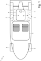
- number 1 indicates a car as a whole comprising two steered front wheels 2 and two driven rear wheels 3.
- the car 1 comprises an internal combustion heat engine 4 in a central position which transmits motion to the rear driven wheels 3.
- the car 1 comprises a cabin 5 which is arranged in front of the internal combustion heat engine 4 (and close to the internal combustion heat engine 4) and accommodates a pair of seats for the driver and for a passenger.
- the internal combustion heat engine 4 is provided with a filtering device 6 for the supply of fresh air, which receives the air from the outside through two (dynamic) air intakes 7 formed on the two opposite sides of the car 1 and feeds the filtered air toward the cylinders of the internal combustion heat engine 4 through a single outlet opening 8 arranged in a central position.
- the filtering device 6 is arranged on top of the internal combustion heat engine 4 and the outlet opening 8 thus opens downwards.
- the internal combustion heat engine 4 comprises an intake system which is provided on the inlet side with (at least) one butterfly valve which regulates the inlet of fresh air to the interior of a corresponding intake manifold which communicates with the cylinders by means of respective intake channels. If the cylinders of the internal combustion heat engine 4 are arranged on two distinct banks forming a "V", two intake manifolds, each potentially equipped with a corresponding butterfly valve, could be provided.
- the cabin 5 and the engine compartment i.e. the volume in which the internal combustion heat engine 4 is housed
- the engine compartment is obtained inside the cabin 5 or, from another perspective, the cabin 5 is obtained inside the engine compartment.
- the filtering device 6 comprises an air-box 9 which has, on the inside, a cavity 10 having two inlet openings 11 towards the outside and one single outlet opening 8 towards the intake system of the internal combustion heat engine 4; each inlet opening 11 is in communication with a corresponding air intake 7 by means of a tubular intake channel 12 (illustrated schematically in Figure 1 ); it is important to emphasize that each inlet opening 11 is very close to the corresponding air intake 7 and thus the intake channel 12 is very short and thus with pressure drops very low.
- the filtering device 6 comprises two filters 13, each of which is housed inside the air-box 9 and arranged between a corresponding inlet opening 11 and the outlet opening 8; in particular, the cavity 10 comprises two seats which reproduce, in negative, a part of the shape of the two filters 13 and are designed to house the two filters 13.
- the two filters 13 divide the cavity 10 into a pair of inlet chambers, each of which is arranged upstream of a corresponding filter 13 and communicates with the outside through a corresponding inlet opening 11, and one single outlet chamber, which is arranged downstream of the filters 13 and communicates with the intake system of the internal combustion heat engine 4 through the outlet opening 8.
- a tubular-shaped inlet chamber is defined between an inlet opening 11 and the corresponding filter 13 while the outlet chamber is defined between the two filters 13 and the single outlet opening 8.
- the single outlet chamber has the shape of a "Greek theatre", wherein the outlet opening 8 is formed in the area of the "stage”, which is arranged at the centre and which has a roughly semi-circular or semi-elliptical shape, whereas the two filters 13 (which match and mirror each other) are arranged beside each other in the area of the "stands".
- the single outlet chamber is delimited at the top by a removable lid 14 which can be coupled (as illustrated in Figure 3 ) or uncoupled (as illustrated in Figures 4-7 ) to/from the air-box 9; for instance, the lid 14 could be screwed to the air-box 9.
- each inlet chamber has a tubular shape and extends towards the respective inlet opening 11; consequently, the two inlet chambers opposite each other extend laterally from the outlet chamber and starting from opposite ends of said outlet chamber.
- a locking body 16 is provided, which is interposed between the two filters 13 and fulfils the function of pressing the two filters 13 in order to keep them in the correct position preventing any kind of displacement of the two filters 13 (and thus preventing the two filters 13 from vibrating).
- the locking body 16 has an upper wall 17 which rests against the inner surface of the lid 14 so that the lid 14, when mounted, presses the locking body 16 downward (i.e. forces the locking body 16 against the lower surface of the cavity 10); in other words, the lid presses the upper wall 17 of the locking body 16 in order to force the locking body 16 against a lower wall of the air-box 9 (or against the bottom of the cavity 10).
- the locking body 16 has a wedge-shaped lower portion 18 (or has the shape of a truncated cone) which is placed between the two filters 13 and, as the result of its wedge shape, pushes the two filters 13 gradually and laterally (transversally) while the lid 14 is screwed onto the air-box 9.
- the locking body 16 has an intermediate portion 19 that joins the upper wall 17 to the lower portion 18 and is shaped so as to guide the air flows coming from the filters 13 towards the outlet opening 8; in other words, the intermediate portion 19 of the locking body 16 performs the function of deflecting the air flows coming from the filters 13.
- the air-box 9 is designed to be arranged on top of the internal combustion heat engine 4 so as to constitute an upper cover of the internal combustion heat engine 4; as a result, the air-box 9 has a vertical thickness that is much smaller than a horizontal extension; for instance, the maximum vertical thickness of the air-box 9 is generally in the range 25-35 cm, the transversal width of the air-box 9 is generally in the range 110-160 cm and the longitudinal length of the air-box 9 is generally in the range 60-120 cm.
- the air-box 9 is obtained by joining a lower shell, where the outlet opening 8 is obtained, and an upper shell, where the two inlet openings 11 and an upper opening (facing and opposite the outlet opening 8) closed by the lid 14 are obtained.
- a pair of annular elastic gaskets are also provided, each of which is inserted between an inlet opening 11 and a corresponding intake channel 12 in order to ensure both a pneumatic insulation and an acoustic insulation.
- the lid 14 can be coated on the inside (generally with the exception of the area that presses against the upper wall 17 of the locking body 16) with a sound-absorbing material in order to reduce the acoustic emissions emanating from the air-box 9. Also other parts of the air-box 9 other than the lid 14 can be coated on the inside with a sound-absorbing material in order to reduce the acoustic emissions emanating from the air-box 9.
- At least one replaceable absorbing element 20 is arranged inside the cavity 10 (illustrated schematically in Figure 3 ) designed to hold back polluting elements (in particular HC groups) which could get into the cavity 10 from the internal combustion heat engine 4 through the outlet opening 8 (in particular when the internal combustion heat engine 4 has an EGR system which re-emits a part of the exhaust gas into the intake).
- the absorbing element 20 is mounted on the lid 14 in such a manner as to be easily viewable and replaceable when the lid 14 is detached.
- the filtering device 6 comprises at least one channel for discharging water that originates from a lower wall of the air-box 9 (i.e. from the bottom of the cavity 10) and ends towards the street in order to drain any water entering through the air intakes 7 and accumulating on the bottom of the cavity 10.
- the channel for discharging water is provided with a discharge valve that is normally closed and opens only occasionally (when necessary) in order to allow the discharge of the water; this way, the cavity 10 remains (almost) always insulated from the outside (since the discharge valve is normally closed) and thus the acoustic emissions are reduced to a minimum also through the discharge channel.
- Each filter 13 has a curved profile having a concavity oriented towards the outlet opening 8; in other words, each filter 13 is not plane (flat), but curved (i.e. cup-shaped) and thus has a concavity oriented towards the outlet opening 8.
- Each filter 13 has a curved and open profile, i.e. the filter 13 does not have a closed geometric shape without a beginning or an end (like, for instance, a cylinder or a cone section) but has an open geometric shape that has a beginning and an end.
- each filter 13 has a curved progression configured so that an average of an inner surface of the filter 13 oriented towards the outlet opening 8 has the points that lie on a line parallel to a longitudinal axis 21 of the outlet opening 8 projected onto the inner surface and are equidistant from the longitudinal axis 21.
- each filter 13 has a curved progression configured in such a manner that each point of the inner surface of the filter 13 oriented towards the outlet opening 8 is equidistant from the longitudinal axis 21 of the outlet opening 8; in other words, all the points of the inner surface of the filter 13 oriented towards the outlet opening 8 are located at the same distance from the longitudinal axis 21 of the outlet opening 8.
- each filter 13 has a curved progression on a cylindrical generatrix centred on the longitudinal axis 21 of the outlet opening 8; i.e. each filter 13 lies on a section of a cylindrical surface centred on the longitudinal axis 21 of the outlet opening 8.
- the cylindrical generatrix of the plane progression of each filter can have a constant radius (thus all points of the inner surface of the filter 13 are at the same distance from the longitudinal axis 21 of the outlet opening 8) or can have a variable radius (thus the points of the inner surface of the filter 13 are at a variable distance from the longitudinal axis 21 of the outlet opening 8).
- the filtering device 6 described above has numerous advantages.
- the filtering device 6 described above allows reducing the emission of noise by the filtering device 6 to very low levels and thus allows using said filtering device 6 also in a car 1 (in particular with a central engine) in which there is no effective separation between the cabin 5 and the engine compartment (i.e. the volume in which the internal combustion heat engine 4 is housed and thus also the filtering device 6).
- the filtering device 6 described above has a relatively reduced bulk (if compared to the overall volume of the cavity 10 and to the extension of the filters 13) and, above all, can be installed easily on top of the internal combustion heat engine 4 (i.e. in an area which is always sufficiently free even in sports cars 1 with a central engine).
- the filtering device 6 described above allows achieving very high performances, i.e. allows taking in a large air load with modest pressure losses, as a result of the large free passage area of the two filters 13 and as a result of the configuration of the cavity 10 which optimizes the air-flow paths.
- the curved configuration of the filters 13 allows creating a filtering device 6 with an enhanced performance which improves the performance of the air-box in terms of its fluid dynamics and, at the same time, allows saving space by realizing a smaller filtering device 6 with reduced pressure losses.
Landscapes
- Engineering & Computer Science (AREA)
- Chemical & Material Sciences (AREA)
- Combustion & Propulsion (AREA)
- Mechanical Engineering (AREA)
- General Engineering & Computer Science (AREA)
- Chemical Kinetics & Catalysis (AREA)
- Physics & Mathematics (AREA)
- Geometry (AREA)
- Manufacturing & Machinery (AREA)
- Filtering Of Dispersed Particles In Gases (AREA)
Claims (13)
- Filtervorrichtung (6) für Luft, die von einem Verbrennungsmotor bzw. einer Verbrennungswärmekraftmaschine (4) eines Autos (1) angesaugt wird, wobei die Filtervorrichtung (6) umfasst:eine Airbox bzw. einen Luftkasten (9), der innen einen einzelnen Hohlraum (10) mit zwei gegenüberliegenden bzw. entgegengesetzten Einlassöffnungen (11) nach außen hin und einer einzelnen Auslassöffnung (8) zu der Verbrennungswärmekraftmaschine (4) hin umfasst; undzwei Filter (13), die innerhalb des Hohlraums (10) zwischen der Einlassöffnung (11) und der Auslassöffnung (8) angeordnet sind und den Hohlraum (10) in eine einzelne Auslasskammer, die stromabwärts der Filter (13) angeordnet ist und mit der Verbrennungswärmekraftmaschine (4) durch die Auslassöffnung (8) kommuniziert, und in zwei Einlasskammern unterteilen, die gegenüberliegenden bzw. entgegengesetzten Seiten der Auslasskammer zugewandt sind, stromaufwärts der jeweiligen Filter (13) angeordnet sind und mit der Außenseite durch die jeweiligen Einlassöffnungen (11) kommunizieren;wobei die Filtervorrichtung (6) dadurch gekennzeichnet ist, dass:jeder Filter (13) ein gekrümmtes und offenes Profil mit einer Konkavität aufweist, die zu der Auslassöffnung (8) hin ausgerichtet ist; unddie einzelne Auslasskammer die Form eines "Griechischen Theaters" aufweist, wobei sich in dem Bereich der "Bühne", die in der Mitte angeordnet ist, die Auslassöffnung (8) befindet, während in dem Bereich der "Tribünen" die zwei Filter (13) nebeneinander sind.
- Filtervorrichtung (6) nach Anspruch 1, dadurch gekennzeichnet, dass jeder Filter (13) einen gekrümmten Verlauf aufweist, der so konfiguriert ist, dass im Mittel eine der Auslassöffnung (8) zugewandte innere Fläche bzw. Oberfläche des Filters (13) die Punkte aufweist, die auf einer Linie parallel zu einer Längsachse (21) der Auslassöffnung (8) liegen, die auf die innere Fläche projiziert wird, und die von der Längsachse (21) gleichweit entfernt sind.
- Filtervorrichtung (6) nach Anspruch 1 oder 2, wobei jeder Filter (13) einen gekrümmten Verlauf auf einer zylindrischen Erzeugenden aufweist, die auf einer Längsachse (21) der Auslassöffnung (8) zentriert ist.
- Filtervorrichtung (6) nach Anspruch 1, 2 oder 3 und umfassend einen Verriegelungskörper (16), der zwischen den beiden Filtern (13) angeordnet ist und die Funktion des lateralen Pressens der beiden Filter (13) erfüllt.
- Filtervorrichtung (6) nach einem der Ansprüche 1 bis 4, wobei die einzelne Auslasskammer oben durch einen abnehmbaren Deckel (14) begrenzt ist.
- Filtervorrichtung (6) nach Anspruch 5, wobei:ein Verriegelungskörper (16) bereitgestellt ist, der zwischen den beiden Filtern (13) angeordnet ist und die Funktion des lateralen Pressens der beiden Filter (13) erfüllt;der Verriegelungskörper (16) eine obere Wand (17) aufweist, die an einer inneren Fläche bzw. Oberfläche des Deckels (14) anliegt, so dass der Deckel (14) den Verriegelungskörper (16) zu einem Boden des Hohlraums (10) hin presst; undder Verriegelungskörper (16) einen unteren Abschnitt (18) aufweist, der keilförmig ist und zwischen den beiden Filtern (13) angeordnet ist.
- Filtervorrichtung (6) nach Anspruch 6, wobei der Verriegelungskörper (16) einen Zwischenabschnitt (19) aufweist, der die obere Wand (17) mit dem unteren Abschnitt (18) verbindet und so geformt ist, dass er die Luftströme von den Filtern (13) kommend zu der Auslassöffnung (8) hin führt.
- Filtervorrichtung (6) nach Anspruch 5, 6 oder 7, wobei der Luftkasten (9) erhalten wird durch Verbinden einer unteren Schale, wo die Auslassöffnung (8) erhalten wird, und einer oberen Schale, wo die zwei Einlassöffnungen (11) sowie eine obere Öffnung erhalten werden, die der Auslassöffnung (8) gegenüberliegend bzw. entgegengesetzt ist und durch den Deckel (14) verschlossen ist.
- Filtervorrichtung (6) nach einem der Ansprüche 5 bis 8, wobei der Deckel (14) auf der Innenseite mit einem schallabsorbierenden Material beschichtet ist.
- Filtervorrichtung (6) nach einem der Ansprüche 1 bis 9, wobei:jede Einlasskammer eine rohrförmige Form aufweist und sich zu der entsprechenden Einlassöffnung (11) hin erstreckt; unddie zwei Einlasskammern sich lateral von der Auslasskammer erstrecken und von gegenüberliegenden bzw. entgegengesetzten Enden der Auslasskammer beginnen.
- Filtervorrichtung (6) nach einem der Ansprüche 1 bis 10, wobei der Hohlraum (10) zwei Sitze umfasst, die die Form der zwei Filter (13) negativ nachbilden und ausgelegt sind, die zwei Filter (13) aufzunehmen.
- Filtervorrichtung (6) nach einem der Ansprüche 1 bis 11 und umfassend ein absorbierendes Element (20), das innerhalb des Hohlraums (10) angeordnet und ausgelegt ist, Schadstoffe zurückzuhalten.
- Auto (1), umfassend:ein Paar Vorderräder (2);ein Paar Hinterräder (3);einen Verbrennungsmotor bzw. eine Verbrennungswärmekraftmaschine (4), der bzw. die in einer zentralen Position angeordnet ist;zwei Lufteinlässe (7), die auf zwei gegenüberliegenden bzw. entgegengesetzten Körper- bzw. Karosserieseiten erhalten sind;eine Filtervorrichtung (6), die gemäß einem der Ansprüche 1 bis 12 realisiert ist; undzwei Einlass- bzw. Ansaugkanäle (12), die jeweils einen Lufteinlass (7) mit einer entsprechenden Einlassöffnung (11) des Luftkastens (9) verbinden.
Applications Claiming Priority (1)
| Application Number | Priority Date | Filing Date | Title |
|---|---|---|---|
| IT102019000005872A IT201900005872A1 (it) | 2019-04-16 | 2019-04-16 | Dispositivo filtrante per l'aria aspirata da un motore di una automobile ed automobile provvista del dispositivo filtrante |
Publications (2)
| Publication Number | Publication Date |
|---|---|
| EP3726045A1 EP3726045A1 (de) | 2020-10-21 |
| EP3726045B1 true EP3726045B1 (de) | 2023-03-29 |
Family
ID=67875863
Family Applications (1)
| Application Number | Title | Priority Date | Filing Date |
|---|---|---|---|
| EP20169951.9A Active EP3726045B1 (de) | 2019-04-16 | 2020-04-16 | Filtervorrichtung für die vom motor eines kraftfahrzeuges angesaugte luft und mit der filtervorrichtung ausgerüstetes kraftfahrzeug |
Country Status (2)
| Country | Link |
|---|---|
| EP (1) | EP3726045B1 (de) |
| IT (1) | IT201900005872A1 (de) |
Families Citing this family (1)
| Publication number | Priority date | Publication date | Assignee | Title |
|---|---|---|---|---|
| IT202300018309A1 (it) * | 2023-09-06 | 2025-03-06 | Bmc Srl | Dispositivo audio |
Citations (1)
| Publication number | Priority date | Publication date | Assignee | Title |
|---|---|---|---|---|
| DE202007003941U1 (de) * | 2007-03-17 | 2008-07-24 | Hengst Gmbh & Co.Kg | Körper aus einem Schall absorbierenden Material |
Family Cites Families (7)
| Publication number | Priority date | Publication date | Assignee | Title |
|---|---|---|---|---|
| JP2524354B2 (ja) * | 1987-06-09 | 1996-08-14 | 日産自動車株式会社 | 内燃機関用エアクリ−ナ |
| DE10043532B4 (de) * | 2000-09-05 | 2010-11-04 | Dr. Ing. H.C. F. Porsche Aktiengesellschaft | Luftfiltereinrichtung für eine mehrzylindrige Brennkraftmaschine |
| JP3942887B2 (ja) * | 2001-12-26 | 2007-07-11 | 株式会社日本自動車部品総合研究所 | 蒸発燃料吸着材及びエアクリーナ |
| US6726720B2 (en) | 2002-03-27 | 2004-04-27 | Depuy Spine, Inc. | Modular disc prosthesis |
| DE102004015331B4 (de) * | 2004-02-02 | 2021-05-27 | Daimler Ag | Luftfiltersystem |
| US10035093B2 (en) * | 2016-06-15 | 2018-07-31 | Mann+Hummel Gmbh | Air filtering assembly for a motor vehicle |
| JP2018062867A (ja) * | 2016-10-11 | 2018-04-19 | トヨタ紡織株式会社 | 吸気系部品 |
-
2019
- 2019-04-16 IT IT102019000005872A patent/IT201900005872A1/it unknown
-
2020
- 2020-04-16 EP EP20169951.9A patent/EP3726045B1/de active Active
Patent Citations (1)
| Publication number | Priority date | Publication date | Assignee | Title |
|---|---|---|---|---|
| DE202007003941U1 (de) * | 2007-03-17 | 2008-07-24 | Hengst Gmbh & Co.Kg | Körper aus einem Schall absorbierenden Material |
Also Published As
| Publication number | Publication date |
|---|---|
| IT201900005872A1 (it) | 2020-10-16 |
| EP3726045A1 (de) | 2020-10-21 |
Similar Documents
| Publication | Publication Date | Title |
|---|---|---|
| US8241382B2 (en) | Air cleaner for motor vehicles operating in extreme weather conditions | |
| CN105971783B (zh) | 车辆的进气音传递装置 | |
| US20030230273A1 (en) | Fresh gas supply system for a combustion engine | |
| US20140326215A1 (en) | Arrangement of an Air Supply Device on a Cylinder Head for an Internal Combustion Engine | |
| US6868843B2 (en) | Engine blowby gas processing system | |
| EP3726045B1 (de) | Filtervorrichtung für die vom motor eines kraftfahrzeuges angesaugte luft und mit der filtervorrichtung ausgerüstetes kraftfahrzeug | |
| US6474284B1 (en) | Air-routing system, especially a suction system of an internal combustion engine | |
| US12584429B2 (en) | Engine crankcase ventilation system | |
| US6092499A (en) | Intake pipe | |
| CN112282990A (zh) | 一种汽车空气滤清器结构 | |
| CN107725145B (zh) | 一种曲轴箱通风系统 | |
| US20170089305A1 (en) | Canister apparatus for vehicle | |
| US5983873A (en) | Endothermal engine provided with a device for purifying the blow-by gases of the block | |
| US10054086B2 (en) | Filter box assembly for a branched intake system | |
| DE102013207586A1 (de) | Luftfilter mit integriertem Resonator | |
| US8001945B2 (en) | Resonator for an intake system of a motor vehicle | |
| EP3749847B1 (de) | Motorluftfilter mit integriertem kompressordämpfer | |
| EP3165734B1 (de) | Im schalldämpfer integrierter ottopartikelfilter | |
| KR100273168B1 (ko) | 자동차 액체연료탱크의 연료공급장치 | |
| CN210178496U (zh) | 一种谐振消声空滤器 | |
| CN207315473U (zh) | 一种汽车发动机油气分离器 | |
| KR100756623B1 (ko) | 자동차 엔진의 흡기소음 저감장치 | |
| KR101241510B1 (ko) | 차량용 서지탱크 | |
| JP2021042731A (ja) | 固定構造 |
Legal Events
| Date | Code | Title | Description |
|---|---|---|---|
| PUAI | Public reference made under article 153(3) epc to a published international application that has entered the european phase |
Free format text: ORIGINAL CODE: 0009012 |
|
| STAA | Information on the status of an ep patent application or granted ep patent |
Free format text: STATUS: THE APPLICATION HAS BEEN PUBLISHED |
|
| AK | Designated contracting states |
Kind code of ref document: A1 Designated state(s): AL AT BE BG CH CY CZ DE DK EE ES FI FR GB GR HR HU IE IS IT LI LT LU LV MC MK MT NL NO PL PT RO RS SE SI SK SM TR |
|
| AX | Request for extension of the european patent |
Extension state: BA ME |
|
| STAA | Information on the status of an ep patent application or granted ep patent |
Free format text: STATUS: REQUEST FOR EXAMINATION WAS MADE |
|
| 17P | Request for examination filed |
Effective date: 20201215 |
|
| RBV | Designated contracting states (corrected) |
Designated state(s): AL AT BE BG CH CY CZ DE DK EE ES FI FR GB GR HR HU IE IS IT LI LT LU LV MC MK MT NL NO PL PT RO RS SE SI SK SM TR |
|
| RIC1 | Information provided on ipc code assigned before grant |
Ipc: B01D 46/58 20220101ALI20220803BHEP Ipc: B01D 46/42 20060101ALI20220803BHEP Ipc: B01D 46/24 20060101ALI20220803BHEP Ipc: F02M 35/10 20060101ALI20220803BHEP Ipc: B01D 46/12 20060101ALI20220803BHEP Ipc: F02M 35/12 20060101ALI20220803BHEP Ipc: F02M 35/04 20060101ALI20220803BHEP Ipc: B01D 46/00 20060101ALI20220803BHEP Ipc: F02M 35/024 20060101ALI20220803BHEP Ipc: F02M 35/02 20060101AFI20220803BHEP |
|
| GRAP | Despatch of communication of intention to grant a patent |
Free format text: ORIGINAL CODE: EPIDOSNIGR1 |
|
| STAA | Information on the status of an ep patent application or granted ep patent |
Free format text: STATUS: GRANT OF PATENT IS INTENDED |
|
| INTG | Intention to grant announced |
Effective date: 20221013 |
|
| GRAS | Grant fee paid |
Free format text: ORIGINAL CODE: EPIDOSNIGR3 |
|
| GRAA | (expected) grant |
Free format text: ORIGINAL CODE: 0009210 |
|
| STAA | Information on the status of an ep patent application or granted ep patent |
Free format text: STATUS: THE PATENT HAS BEEN GRANTED |
|
| AK | Designated contracting states |
Kind code of ref document: B1 Designated state(s): AL AT BE BG CH CY CZ DE DK EE ES FI FR GB GR HR HU IE IS IT LI LT LU LV MC MK MT NL NO PL PT RO RS SE SI SK SM TR |
|
| REG | Reference to a national code |
Ref country code: CH Ref legal event code: EP |
|
| REG | Reference to a national code |
Ref country code: DE Ref legal event code: R096 Ref document number: 602020009141 Country of ref document: DE |
|
| REG | Reference to a national code |
Ref country code: AT Ref legal event code: REF Ref document number: 1556823 Country of ref document: AT Kind code of ref document: T Effective date: 20230415 |
|
| REG | Reference to a national code |
Ref country code: IE Ref legal event code: FG4D |
|
| REG | Reference to a national code |
Ref country code: LT Ref legal event code: MG9D |
|
| PG25 | Lapsed in a contracting state [announced via postgrant information from national office to epo] |
Ref country code: RS Free format text: LAPSE BECAUSE OF FAILURE TO SUBMIT A TRANSLATION OF THE DESCRIPTION OR TO PAY THE FEE WITHIN THE PRESCRIBED TIME-LIMIT Effective date: 20230329 Ref country code: NO Free format text: LAPSE BECAUSE OF FAILURE TO SUBMIT A TRANSLATION OF THE DESCRIPTION OR TO PAY THE FEE WITHIN THE PRESCRIBED TIME-LIMIT Effective date: 20230629 Ref country code: LV Free format text: LAPSE BECAUSE OF FAILURE TO SUBMIT A TRANSLATION OF THE DESCRIPTION OR TO PAY THE FEE WITHIN THE PRESCRIBED TIME-LIMIT Effective date: 20230329 Ref country code: LT Free format text: LAPSE BECAUSE OF FAILURE TO SUBMIT A TRANSLATION OF THE DESCRIPTION OR TO PAY THE FEE WITHIN THE PRESCRIBED TIME-LIMIT Effective date: 20230329 Ref country code: HR Free format text: LAPSE BECAUSE OF FAILURE TO SUBMIT A TRANSLATION OF THE DESCRIPTION OR TO PAY THE FEE WITHIN THE PRESCRIBED TIME-LIMIT Effective date: 20230329 |
|
| REG | Reference to a national code |
Ref country code: NL Ref legal event code: MP Effective date: 20230329 |
|
| REG | Reference to a national code |
Ref country code: AT Ref legal event code: MK05 Ref document number: 1556823 Country of ref document: AT Kind code of ref document: T Effective date: 20230329 |
|
| PG25 | Lapsed in a contracting state [announced via postgrant information from national office to epo] |
Ref country code: SE Free format text: LAPSE BECAUSE OF FAILURE TO SUBMIT A TRANSLATION OF THE DESCRIPTION OR TO PAY THE FEE WITHIN THE PRESCRIBED TIME-LIMIT Effective date: 20230329 Ref country code: NL Free format text: LAPSE BECAUSE OF FAILURE TO SUBMIT A TRANSLATION OF THE DESCRIPTION OR TO PAY THE FEE WITHIN THE PRESCRIBED TIME-LIMIT Effective date: 20230329 Ref country code: GR Free format text: LAPSE BECAUSE OF FAILURE TO SUBMIT A TRANSLATION OF THE DESCRIPTION OR TO PAY THE FEE WITHIN THE PRESCRIBED TIME-LIMIT Effective date: 20230630 Ref country code: FI Free format text: LAPSE BECAUSE OF FAILURE TO SUBMIT A TRANSLATION OF THE DESCRIPTION OR TO PAY THE FEE WITHIN THE PRESCRIBED TIME-LIMIT Effective date: 20230329 |
|
| PG25 | Lapsed in a contracting state [announced via postgrant information from national office to epo] |
Ref country code: SM Free format text: LAPSE BECAUSE OF FAILURE TO SUBMIT A TRANSLATION OF THE DESCRIPTION OR TO PAY THE FEE WITHIN THE PRESCRIBED TIME-LIMIT Effective date: 20230329 Ref country code: RO Free format text: LAPSE BECAUSE OF FAILURE TO SUBMIT A TRANSLATION OF THE DESCRIPTION OR TO PAY THE FEE WITHIN THE PRESCRIBED TIME-LIMIT Effective date: 20230329 Ref country code: PT Free format text: LAPSE BECAUSE OF FAILURE TO SUBMIT A TRANSLATION OF THE DESCRIPTION OR TO PAY THE FEE WITHIN THE PRESCRIBED TIME-LIMIT Effective date: 20230731 Ref country code: ES Free format text: LAPSE BECAUSE OF FAILURE TO SUBMIT A TRANSLATION OF THE DESCRIPTION OR TO PAY THE FEE WITHIN THE PRESCRIBED TIME-LIMIT Effective date: 20230329 Ref country code: EE Free format text: LAPSE BECAUSE OF FAILURE TO SUBMIT A TRANSLATION OF THE DESCRIPTION OR TO PAY THE FEE WITHIN THE PRESCRIBED TIME-LIMIT Effective date: 20230329 Ref country code: AT Free format text: LAPSE BECAUSE OF FAILURE TO SUBMIT A TRANSLATION OF THE DESCRIPTION OR TO PAY THE FEE WITHIN THE PRESCRIBED TIME-LIMIT Effective date: 20230329 |
|
| PG25 | Lapsed in a contracting state [announced via postgrant information from national office to epo] |
Ref country code: SK Free format text: LAPSE BECAUSE OF FAILURE TO SUBMIT A TRANSLATION OF THE DESCRIPTION OR TO PAY THE FEE WITHIN THE PRESCRIBED TIME-LIMIT Effective date: 20230329 Ref country code: PL Free format text: LAPSE BECAUSE OF FAILURE TO SUBMIT A TRANSLATION OF THE DESCRIPTION OR TO PAY THE FEE WITHIN THE PRESCRIBED TIME-LIMIT Effective date: 20230329 Ref country code: IS Free format text: LAPSE BECAUSE OF FAILURE TO SUBMIT A TRANSLATION OF THE DESCRIPTION OR TO PAY THE FEE WITHIN THE PRESCRIBED TIME-LIMIT Effective date: 20230729 |
|
| REG | Reference to a national code |
Ref country code: CH Ref legal event code: PL |
|
| PG25 | Lapsed in a contracting state [announced via postgrant information from national office to epo] |
Ref country code: LU Free format text: LAPSE BECAUSE OF NON-PAYMENT OF DUE FEES Effective date: 20230416 |
|
| REG | Reference to a national code |
Ref country code: DE Ref legal event code: R097 Ref document number: 602020009141 Country of ref document: DE |
|
| REG | Reference to a national code |
Ref country code: BE Ref legal event code: MM Effective date: 20230430 |
|
| PG25 | Lapsed in a contracting state [announced via postgrant information from national office to epo] |
Ref country code: MC Free format text: LAPSE BECAUSE OF FAILURE TO SUBMIT A TRANSLATION OF THE DESCRIPTION OR TO PAY THE FEE WITHIN THE PRESCRIBED TIME-LIMIT Effective date: 20230329 |
|
| PG25 | Lapsed in a contracting state [announced via postgrant information from national office to epo] |
Ref country code: MC Free format text: LAPSE BECAUSE OF FAILURE TO SUBMIT A TRANSLATION OF THE DESCRIPTION OR TO PAY THE FEE WITHIN THE PRESCRIBED TIME-LIMIT Effective date: 20230329 Ref country code: LI Free format text: LAPSE BECAUSE OF NON-PAYMENT OF DUE FEES Effective date: 20230430 Ref country code: DK Free format text: LAPSE BECAUSE OF FAILURE TO SUBMIT A TRANSLATION OF THE DESCRIPTION OR TO PAY THE FEE WITHIN THE PRESCRIBED TIME-LIMIT Effective date: 20230329 Ref country code: CZ Free format text: LAPSE BECAUSE OF FAILURE TO SUBMIT A TRANSLATION OF THE DESCRIPTION OR TO PAY THE FEE WITHIN THE PRESCRIBED TIME-LIMIT Effective date: 20230329 Ref country code: CH Free format text: LAPSE BECAUSE OF NON-PAYMENT OF DUE FEES Effective date: 20230430 |
|
| PLBE | No opposition filed within time limit |
Free format text: ORIGINAL CODE: 0009261 |
|
| STAA | Information on the status of an ep patent application or granted ep patent |
Free format text: STATUS: NO OPPOSITION FILED WITHIN TIME LIMIT |
|
| REG | Reference to a national code |
Ref country code: IE Ref legal event code: MM4A |
|
| PG25 | Lapsed in a contracting state [announced via postgrant information from national office to epo] |
Ref country code: BE Free format text: LAPSE BECAUSE OF NON-PAYMENT OF DUE FEES Effective date: 20230430 |
|
| 26N | No opposition filed |
Effective date: 20240103 |
|
| PG25 | Lapsed in a contracting state [announced via postgrant information from national office to epo] |
Ref country code: IE Free format text: LAPSE BECAUSE OF NON-PAYMENT OF DUE FEES Effective date: 20230416 |
|
| PG25 | Lapsed in a contracting state [announced via postgrant information from national office to epo] |
Ref country code: IE Free format text: LAPSE BECAUSE OF NON-PAYMENT OF DUE FEES Effective date: 20230416 |
|
| PG25 | Lapsed in a contracting state [announced via postgrant information from national office to epo] |
Ref country code: SI Free format text: LAPSE BECAUSE OF FAILURE TO SUBMIT A TRANSLATION OF THE DESCRIPTION OR TO PAY THE FEE WITHIN THE PRESCRIBED TIME-LIMIT Effective date: 20230329 |
|
| PG25 | Lapsed in a contracting state [announced via postgrant information from national office to epo] |
Ref country code: SI Free format text: LAPSE BECAUSE OF FAILURE TO SUBMIT A TRANSLATION OF THE DESCRIPTION OR TO PAY THE FEE WITHIN THE PRESCRIBED TIME-LIMIT Effective date: 20230329 Ref country code: FR Free format text: LAPSE BECAUSE OF NON-PAYMENT OF DUE FEES Effective date: 20230529 |
|
| PG25 | Lapsed in a contracting state [announced via postgrant information from national office to epo] |
Ref country code: BG Free format text: LAPSE BECAUSE OF FAILURE TO SUBMIT A TRANSLATION OF THE DESCRIPTION OR TO PAY THE FEE WITHIN THE PRESCRIBED TIME-LIMIT Effective date: 20230329 |
|
| PG25 | Lapsed in a contracting state [announced via postgrant information from national office to epo] |
Ref country code: BG Free format text: LAPSE BECAUSE OF FAILURE TO SUBMIT A TRANSLATION OF THE DESCRIPTION OR TO PAY THE FEE WITHIN THE PRESCRIBED TIME-LIMIT Effective date: 20230329 |
|
| GBPC | Gb: european patent ceased through non-payment of renewal fee |
Effective date: 20240416 |
|
| PG25 | Lapsed in a contracting state [announced via postgrant information from national office to epo] |
Ref country code: GB Free format text: LAPSE BECAUSE OF NON-PAYMENT OF DUE FEES Effective date: 20240416 |
|
| PG25 | Lapsed in a contracting state [announced via postgrant information from national office to epo] |
Ref country code: GB Free format text: LAPSE BECAUSE OF NON-PAYMENT OF DUE FEES Effective date: 20240416 |
|
| PGFP | Annual fee paid to national office [announced via postgrant information from national office to epo] |
Ref country code: DE Payment date: 20250428 Year of fee payment: 6 |
|
| PGFP | Annual fee paid to national office [announced via postgrant information from national office to epo] |
Ref country code: IT Payment date: 20250402 Year of fee payment: 6 |
|
| PG25 | Lapsed in a contracting state [announced via postgrant information from national office to epo] |
Ref country code: CY Free format text: LAPSE BECAUSE OF FAILURE TO SUBMIT A TRANSLATION OF THE DESCRIPTION OR TO PAY THE FEE WITHIN THE PRESCRIBED TIME-LIMIT; INVALID AB INITIO Effective date: 20200416 |
|
| PG25 | Lapsed in a contracting state [announced via postgrant information from national office to epo] |
Ref country code: HU Free format text: LAPSE BECAUSE OF FAILURE TO SUBMIT A TRANSLATION OF THE DESCRIPTION OR TO PAY THE FEE WITHIN THE PRESCRIBED TIME-LIMIT; INVALID AB INITIO Effective date: 20200416 |
|
| PG25 | Lapsed in a contracting state [announced via postgrant information from national office to epo] |
Ref country code: TR Free format text: LAPSE BECAUSE OF FAILURE TO SUBMIT A TRANSLATION OF THE DESCRIPTION OR TO PAY THE FEE WITHIN THE PRESCRIBED TIME-LIMIT Effective date: 20230329 |