EP3725946A1 - Construction apparatus - Google Patents
Construction apparatus Download PDFInfo
- Publication number
- EP3725946A1 EP3725946A1 EP18888520.6A EP18888520A EP3725946A1 EP 3725946 A1 EP3725946 A1 EP 3725946A1 EP 18888520 A EP18888520 A EP 18888520A EP 3725946 A1 EP3725946 A1 EP 3725946A1
- Authority
- EP
- European Patent Office
- Prior art keywords
- laying
- installation
- boring
- locations
- magnetic
- Prior art date
- Legal status (The legal status is an assumption and is not a legal conclusion. Google has not performed a legal analysis and makes no representation as to the accuracy of the status listed.)
- Withdrawn
Links
Images




Classifications
-
- E—FIXED CONSTRUCTIONS
- E01—CONSTRUCTION OF ROADS, RAILWAYS, OR BRIDGES
- E01C—CONSTRUCTION OF, OR SURFACES FOR, ROADS, SPORTS GROUNDS, OR THE LIKE; MACHINES OR AUXILIARY TOOLS FOR CONSTRUCTION OR REPAIR
- E01C23/00—Auxiliary devices or arrangements for constructing, repairing, reconditioning, or taking-up road or like surfaces
- E01C23/16—Devices for marking-out, applying, or forming traffic or like markings on finished paving; Protecting fresh markings
- E01C23/18—Devices for marking-out, applying, or forming traffic or like markings on finished paving; Protecting fresh markings for applying prefabricated markings
-
- G—PHYSICS
- G05—CONTROLLING; REGULATING
- G05D—SYSTEMS FOR CONTROLLING OR REGULATING NON-ELECTRIC VARIABLES
- G05D1/00—Control of position, course, altitude or attitude of land, water, air or space vehicles, e.g. using automatic pilots
- G05D1/02—Control of position or course in two dimensions
- G05D1/021—Control of position or course in two dimensions specially adapted to land vehicles
- G05D1/0259—Control of position or course in two dimensions specially adapted to land vehicles using magnetic or electromagnetic means
- G05D1/0261—Control of position or course in two dimensions specially adapted to land vehicles using magnetic or electromagnetic means using magnetic plots
-
- E—FIXED CONSTRUCTIONS
- E01—CONSTRUCTION OF ROADS, RAILWAYS, OR BRIDGES
- E01C—CONSTRUCTION OF, OR SURFACES FOR, ROADS, SPORTS GROUNDS, OR THE LIKE; MACHINES OR AUXILIARY TOOLS FOR CONSTRUCTION OR REPAIR
- E01C23/00—Auxiliary devices or arrangements for constructing, repairing, reconditioning, or taking-up road or like surfaces
- E01C23/16—Devices for marking-out, applying, or forming traffic or like markings on finished paving; Protecting fresh markings
- E01C23/163—Devices for marking-out, applying, or forming traffic or like markings on finished paving; Protecting fresh markings for marking-out the location of the markings; Guiding or steering devices for marking apparatus, e.g. sights
-
- E—FIXED CONSTRUCTIONS
- E01—CONSTRUCTION OF ROADS, RAILWAYS, OR BRIDGES
- E01F—ADDITIONAL WORK, SUCH AS EQUIPPING ROADS OR THE CONSTRUCTION OF PLATFORMS, HELICOPTER LANDING STAGES, SIGNS, SNOW FENCES, OR THE LIKE
- E01F11/00—Road engineering aspects of Embedding pads or other sensitive devices in paving or other road surfaces, e.g. traffic detectors, vehicle-operated pressure-sensitive actuators, devices for monitoring atmospheric or road conditions
-
- E—FIXED CONSTRUCTIONS
- E01—CONSTRUCTION OF ROADS, RAILWAYS, OR BRIDGES
- E01F—ADDITIONAL WORK, SUCH AS EQUIPPING ROADS OR THE CONSTRUCTION OF PLATFORMS, HELICOPTER LANDING STAGES, SIGNS, SNOW FENCES, OR THE LIKE
- E01F9/00—Arrangement of road signs or traffic signals; Arrangements for enforcing caution
- E01F9/30—Arrangements interacting with transmitters or receivers otherwise than by visible means, e.g. using radar reflectors or radio transmitters
-
- E—FIXED CONSTRUCTIONS
- E01—CONSTRUCTION OF ROADS, RAILWAYS, OR BRIDGES
- E01F—ADDITIONAL WORK, SUCH AS EQUIPPING ROADS OR THE CONSTRUCTION OF PLATFORMS, HELICOPTER LANDING STAGES, SIGNS, SNOW FENCES, OR THE LIKE
- E01F9/00—Arrangement of road signs or traffic signals; Arrangements for enforcing caution
- E01F9/50—Road surface markings; Kerbs or road edgings, specially adapted for alerting road users
- E01F9/506—Road surface markings; Kerbs or road edgings, specially adapted for alerting road users characterised by the road surface marking material, e.g. comprising additives for improving friction or reflectivity; Methods of forming, installing or applying markings in, on or to road surfaces
- E01F9/512—Preformed road surface markings, e.g. of sheet material; Methods of applying preformed markings
-
- E—FIXED CONSTRUCTIONS
- E01—CONSTRUCTION OF ROADS, RAILWAYS, OR BRIDGES
- E01F—ADDITIONAL WORK, SUCH AS EQUIPPING ROADS OR THE CONSTRUCTION OF PLATFORMS, HELICOPTER LANDING STAGES, SIGNS, SNOW FENCES, OR THE LIKE
- E01F9/00—Arrangement of road signs or traffic signals; Arrangements for enforcing caution
- E01F9/50—Road surface markings; Kerbs or road edgings, specially adapted for alerting road users
- E01F9/506—Road surface markings; Kerbs or road edgings, specially adapted for alerting road users characterised by the road surface marking material, e.g. comprising additives for improving friction or reflectivity; Methods of forming, installing or applying markings in, on or to road surfaces
- E01F9/518—Road surface markings; Kerbs or road edgings, specially adapted for alerting road users characterised by the road surface marking material, e.g. comprising additives for improving friction or reflectivity; Methods of forming, installing or applying markings in, on or to road surfaces formed in situ, e.g. by painting, by casting into the road surface or by deforming the road surface
-
- E—FIXED CONSTRUCTIONS
- E01—CONSTRUCTION OF ROADS, RAILWAYS, OR BRIDGES
- E01F—ADDITIONAL WORK, SUCH AS EQUIPPING ROADS OR THE CONSTRUCTION OF PLATFORMS, HELICOPTER LANDING STAGES, SIGNS, SNOW FENCES, OR THE LIKE
- E01F9/00—Arrangement of road signs or traffic signals; Arrangements for enforcing caution
- E01F9/60—Upright bodies, e.g. marker posts or bollards; Supports for road signs
- E01F9/70—Storing, transporting, placing or retrieving portable devices
Definitions
- the present invention relates to an installation device for laying a magnetic marker in a road.
- vehicular marker detection systems for detecting a magnetic marker laid in a road by a magnetic sensor attached to a vehicle have been known (for example, refer to Patent Literature 1).
- various driving assists such as automatic steering control, lane departure warning, and automatic driving using magnetic markers laid along a lane, can be achieved.
- Patent Literature 1 Japanese Unexamined Patent Application Publication No. 2005-202478
- the above-described conventional magnetic marker has the following problem.
- driving assist such as lane departure warning
- it is required to lay many magnetic markers at relatively short spacing with high position accuracy, thereby posing a problem in which installation cost tends to increase.
- the present invention was made in view of the above-described conventional problem, and is to provide a magnetic marker installation device capable of suppressing installation cost by efficient installation.
- the present invention resides in an installation device for laying a magnetic marker in a road, including an operation unit which provides a laying position for the magnetic marker, wherein the installation device is capable of providing the laying position for the magnetic marker at each of a plurality of locations without moving, the plurality of locations having a predetermined relative position relation.
- the installation device of the present invention can provide laying positions for magnetic markers at the plurality of locations without moving.
- the installation device of the present invention is a useful device capable of suppressing installation cost by efficient installation.
- an installation device for laying a magnetic marker in a road in addition to a device which arranges the magnetic marker in the road, a device which performs a preparation operation and so forth for laying the magnetic marker may be used, the preparation operation including, for example, boring an accommodation hole of the magnetic marker or providing a mark for identifying a laying position on a road.
- the preparation operation including, for example, boring an accommodation hole of the magnetic marker or providing a mark for identifying a laying position on a road.
- Completion of magnetic-marker laying by the installation device for laying the magnetic marker in the road is not imperative. For example, even if magnetic-marker laying is not completed but operation of boring the accommodation hole is completed, the position of that accommodation hole is determined as the magnetic-marker laying position.
- the present embodiment is an example regarding an installation device of performing operation of laying magnetic marker 10 in a road. Details of this are described by using FIG. 1 to FIG. 6 .
- Installation cart 2 of FIG. 1 is an installation device which provides a laying position for magnetic marker 10 ( FIG. 2 ) in a road.
- This installation cart 2 bores accommodation hole 108 for accommodating magnetic marker 10 in road surface 100S, thereby determining the laying position for magnetic marker 10.
- Installation cart 2 includes one boring drill (one example of an operation unit) 21 for boring accommodation hole 108 at each of the front and rear of vehicle body 2B. According to this installation cart 2, accommodation holes 108 (laying positions) can be provided at two locations without moving.
- magnetic marker 10 to be installed is a small-sized marker forming a columnar shape having a diameter of 20 mm and a height of 28 mm, as in FIG. 2 .
- the magnet of magnetic marker 10 is a magnet with a magnetic flux density of the surface being 45 mT (millitesla) and the magnetic flux density reaching a height of 250 mm from the surface being on the order of 8 ⁇ T.
- the magnet as an isotropic ferrite plastic magnet has a magnetic material being iron oxide, and is thus resistant to corrosion and not required to be accommodated in a metal-made case or the like.
- Magnetic marker 10 can be directly accommodated and laid in a relatively small accommodation hole 108 ( FIG. 1 ) having, for example, a diameter of 25 mm to 30 mm and a depth on the order of 35 mm to 40 mm.
- Installation cart 2 is, as in FIG. 1 , a four-wheel vehicle including two driving wheels 281 at left and right on a front side of vehicle body 2B and two freewheels 282 at left and right on a rear side.
- Driving wheels 281 at left and right on the front side can be individually driven, and can change the orientation of installation cart 2 in accordance with the rotation difference.
- freewheels 282 at left and right on the rear side the direction of the wheels can be freely changed in accordance with the orientation of installation cart 2.
- the configuration of the wheels of installation cart 2 may be a three-wheel configuration or a six-wheel configuration.
- hand push handle 20 extending rearward over boring drill 21 on the rear side is provided.
- An operator can move installation cart 2 by walking while pushing hand push handle 20.
- Hand push handle 20 is supported in a cantilever manner by operation unit 201 including a sensor, not depicted, for sensing operation forces of both hands of the operator.
- operation unit 201 including a sensor, not depicted, for sensing operation forces of both hands of the operator.
- driving wheels 281 are rotationally driven, thereby causing appropriate assist force.
- the operator can move installation cart 2 with a relatively light force.
- a display panel (not depicted) is attached so as to allow the operator to perform visual inspection, and information such as a moving distance of installation cart 2 is displayed.
- guide roller 280 On the front side of vehicle body 2B, guide roller 280 is attached. With the use of this guide roller 280, visual confirmation as to, for example, whether vehicle body 2B goes along a target line is facilitated. On the rear side of vehicle body 2B, road counter roller 285 is attached for measuring a moving distance.
- Installation cart 2 includes, as in FIG. 1 , in addition to above-described front and rear boring drills 21, power generator 251 which uses light oil as a fuel, driving cylinder 211 which drives boring drills 21 in a vertical direction, suction cleaner 252 which collects dust such as cuttings and so forth.
- Boring drills 21 are driven by driving cylinder 211 to advance and retreat in the vertical direction, but are not displaced in a horizontal direction in relation to vehicle body 2B. That is, the positions of boring drills 21 in a horizontal plane along road surface 100S are constantly held in relation to vehicle body 2B.
- Front and rear boring drills 21 are positioned on center line CL (refer to FIG. 3 ) of vehicle body 2B.
- a relative position relation between front and rear boring drills 21 with respect to center CP of vehicle body 2B is such that front-side boring drill 21 is 1 m ahead of center CP of vehicle body 2B and rear-side boring drill 21 is 1 m behind center CP of vehicle body 2B.
- Offset amounts (OF1 and OF2 in FIG. 1 and FIG. 3 ) representing this relative position relation are set in advance in arithmetic unit 30 (which will be described further below) forming one example of a position information acquisition unit as parameters indicating relative positions of boring drills 21 with respect to center CP of vehicle body 2B.
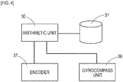
- Installation cart 2 includes, as in FIG. 4 , gyrocompass unit (azimuth information acquisition unit) 36 which measures the azimuth (orientation) of center line CL of vehicle body 2B, encoder 37 which detects a rotation amount of above-described road counter roller 285, and arithmetic unit 30 which finds the boring position of accommodation hole 108 as the laying position for magnetic marker 10.
- gyrocompass unit azimuth information acquisition unit
- encoder 37 which detects a rotation amount of above-described road counter roller 285
- arithmetic unit 30 which finds the boring position of accommodation hole 108 as the laying position for magnetic marker 10.
- Gyrocompass unit 36 is a measurement device which measures the azimuth of a measurement target with respect to true north as a reference azimuth. This gyrocompass unit 36 achieves the above-described measurement by using the gyro effect that the rotation axis of the gyroscope horizontally held on the surface of the rotating earth is along south to north.
- gyrocompass unit 36 is set so that the azimuth of the measurement target is along center line CL of the vehicle body.
- Gyrocompass unit 36 measures the azimuth of center line CL of vehicle body 2B with respect to true north as a reference azimuth, and inputs azimuth information indicating that azimuth to arithmetic unit 30.
- Arithmetic unit 30 ( FIG. 4 ) includes an electronic circuit (not depicted) including a CPU (Central Processing Unit) which performs calculation processing, a ROM (Read Only Memory) and a RAM (Random Access Memory) which store parameters and so forth. Arithmetic unit 30 identifies the position (absolute position) of installation cart 2 during laying operation by using inertial navigation, thereby performing arithmetic processing for identifying the boring position of accommodation hole 108 as a laying position. Position information of the laying position is stored in database 31 and accumulated as laying information of magnetic marker 10.
- CPU Central Processing Unit
- ROM Read Only Memory
- RAM Random Access Memory
- Arithmetic unit 30 computes the moving distance and the relative position of installation cart 2 based on the rotation amount inputted from encoder 37, the azimuth of center line CL inputted from gyrocompass unit 36 and so forth.
- the moving distance is computed by multiplying an integrated value of rotation amounts detected by encoder 37 by the diameter of road counter roller 285 or the like.
- the relative position can be computed by integrating instantaneous displacement amounts (moving distances) along the azimuth of center line CL measured by gyrocompass unit 36 after movement from the reference position with its absolute position identified in advance is started. Note in the present embodiment that center CP of vehicle body 2B is set as a position-measurement location and this position is taken as the position of installation cart 2.
- the operation of laying magnetic marker 10 is performed by using, in addition to installation cart 2 of FIG. 1 for boring accommodation holes 108, an installation cart (not depicted) which arranges magnetic markers 10 one by one in accommodation holes 108, an installation cart (not depicted) which finishes road surface 100S after arrangement of magnetic markers 10 and so forth.
- the installation cart for arrangement is an installation device to arrange magnetic markers 10 in accommodation holes 108 and supply a pavement material as an adhesive.
- the installation cart for finishing the road surface is an installation device which performs operation of cutting a superfluous pavement material swelling from the perimeter of the pavement material after curing the pavement material supplied to accommodation holes 108 to smooth the road surface 100S.
- marking line ML (refer to FIG. 5 ), which is a target line for laying magnetic markers 10, is formed on road surface 100S.
- Marking line ML can be formed by, for example, a vehicle equipped with a device dropping ink, paint, or the like for marking. If this vehicle is caused to travel along a traveling path such as a lane as an installation target, marking line ML, which is a target line for laying magnetic markers 10, can be formed.
- boring accommodation holes 108 as laying positions for magnetic markers 10 can be performed.
- installation cart 2 is preferably stopped every time the moving distance displayed by the above-described display panel is incremented by 10 m.
- front and rear boring drills 21 and so forth are preferably each operated during stopping of installation cart 2.
- a reference position To start movement of installation cart 2 to provide laying locations 10G along the road, it is required to identify the initial position of installation cart 2 in advance as a reference position.
- a method of identifying this reference position for example, there is a method of using a GPS device (not depicted) which measures an absolute position in advance by using a Global Positioning System (GPS).
- GPS Global Positioning System
- the reference position may be identified by measuring the absolute position of center CP of vehicle body 2B by triangulation using surveying devices (not depicted) set at two locations with their absolute positions identified.
- Arithmetic unit 30 integrates momentary displacement amounts based on the rotation amounts detected by encoder 37 along momentary azimuths of center line CL of vehicle body 2B inputted from gyrocompass unit 36, thereby computing the relative position of installation cart 2 with respect to the reference position.
- the relative position calculated by arithmetic unit 30 when installation cart 2 performs laying operation at any laying location 10G is indicated by arrow V.
- arithmetic unit 30 identifies the absolute position of center CP for installation cart 2 while performing laying operation.
- Arithmetic unit 30 performs computation of, as in FIG. 6 , shifting the position along the azimuth of center line CL of vehicle body 2B measured by gyrocompass unit 36 by this offset amount. According to this computation, with reference to the position of center CP of vehicle body 2B, the absolute positions of front and rear boring drills 21 can be identified.
- the absolute positions of accommodation holes 108 at two locations that is, the absolute positions of laying positions 10F
- the position information of laying positions 10F identified as described above is stored in database 31 connected to arithmetic unit 30 and accumulated as laying information of magnetic markers 10.
- installation cart 2 of the present embodiment can provide laying positions 10F for magnetic markers 10 at two locations without moving.
- laying positions 10F at two locations adjacent to each other with a space of 2 m can be efficiently provided at respective laying location 10G.
- To provide laying positions 10F at two locations adjacent to each other with a space of 2 m it is not required to perform positioning, surveying, or the like of installation cart 2 to achieve the space of 2 m with high accuracy. Therefore, by using installation cart 2, laying positions 10F at two locations can be efficiently provided at respective laying locations 10G with high accuracy, and installation cost can be suppressed.
- the position of installation cart 2 while performing laying operation is measured, thereby identifying the absolute position of laying position 10F. According to this installation, it does not take time and effort such as measuring the position with high accuracy or positioning installation cart 2 at a predetermined position with high accuracy. Thus, laying operation can be performed very efficiently. On the other hand, since the position of installation cart 2 is measured while performing laying operation, highly-accurate position information can be acquired for each laying position 10F.
- Installation cart 2 of the present embodiment does not assume position measurement by GPS, and thus can support environments such as the inside of a tunnel where GPS electric waves are not receivable.
- the above-described reference position is preferably set by measuring the absolute position of installation cart 2 at an entrance or exit where measurement of the absolute position by GPS can be performed.
- an installation cart with only one boring drill 21 may be used.
- a plurality of accommodation holes 108 can be preferably bored by moving boring drill 21 in a horizontal plane along road surface 100S.
- an installation cart including three or more boring drills 21 may be used.
- boring drills 21 need not be arrayed on one straight line.
- Three boring drills 21 may be provided so as to form, for example, a triangle.
- the orientation of the triangle can be represented by a deviation angle with respect to the azimuth serving as a reference for, for example, any side of the triangle, a bisector equally dividing the angle of any apex, or the like.
- position information indicating the absolute position of each laying position 10F is stored in database 31 and accumulated as laying information of magnetic markers 10.
- azimuth information indicating the orientation of a line segment (one example of an arrangement shape) connecting laying positions 10F at two locations in respective laying locations 10G may also be stored. Having a predetermined relation (a match in the present embodiment) with the azimuth of center line CL of installation cart 2 (vehicle body 2B) while performing laying operation, the azimuth of this line segment can be easily identified based on the azimuth of center line CL measured by gyrocompass unit 36.
- the present embodiment is an example in which a GPS unit forming one example of the position information acquisition unit is added to the installation cart of the first embodiment. Details of this are described with reference to FIG. 7 .
- GPS unit 38 is, as in FIG. 7 , a unit which receives electric waves from a GPS satellite to measure its absolute position. This GPS unit 38 supports measurement by RTK (RealTime Kinematic)-GPS. GPS unit 38 performs a baseline analysis using a signal received by a fixed station with its absolute position identified, and this can identify a baseline vector from the fixed station to GPS unit 38 to measure the absolute position with high accuracy.
- RTK RealTime Kinematic
- installation cart 2 of the present embodiment includes one GPS unit 38 which measures the absolute position
- this GPS unit 38 has two GPS antennas 381 connected thereto.
- GPS unit 38 measures absolute positions of the installation locations of respective GPS antennas 381.
- GPS antennas 381 are respectively attached directly above front and rear boring drills 21, the position of each boring drill 21 is a position-measurement location.
- two absolute positions measured by GPS unit 38 are boring positions for accommodation holes 108 and laying positions 10F for magnetic markers 10.
- laying position 10F for magnetic marker 10 can be identified by using GPS.
- laying position 10F for magnetic marker 10 can be identified by using inertial navigation . In this manner, by selectively using either of the method of identifying the laying position, the operation of laying magnetic markers 10 including generation of laying information of magnetic markers 10 can be more efficiently performed irrespective of the condition.
- GPS antenna 381 may be attached directly above only either one of boring drills 21.
- the absolute position of the other boring drill 21 can be identified.
- the absolute position of the other boring drill 21 may be identified by shifting the position along the azimuth of center line CL of vehicle body 2B measured by gyrocompass unit.
Landscapes
- Engineering & Computer Science (AREA)
- Architecture (AREA)
- Civil Engineering (AREA)
- Structural Engineering (AREA)
- Physics & Mathematics (AREA)
- Electromagnetism (AREA)
- General Engineering & Computer Science (AREA)
- Aviation & Aerospace Engineering (AREA)
- Radar, Positioning & Navigation (AREA)
- Remote Sensing (AREA)
- General Physics & Mathematics (AREA)
- Automation & Control Theory (AREA)
- Control Of Position, Course, Altitude, Or Attitude Of Moving Bodies (AREA)
- Road Signs Or Road Markings (AREA)
Abstract
Description
- The present invention relates to an installation device for laying a magnetic marker in a road.
- Conventionally, vehicular marker detection systems for detecting a magnetic marker laid in a road by a magnetic sensor attached to a vehicle have been known (for example, refer to Patent Literature 1). According to this marker detection system, various driving assists, such as automatic steering control, lane departure warning, and automatic driving using magnetic markers laid along a lane, can be achieved.
- Patent Literature 1: Japanese Unexamined Patent Application Publication No.
2005-202478 - However, the above-described conventional magnetic marker has the following problem. For example, to achieve driving assist such as lane departure warning, it is required to lay many magnetic markers at relatively short spacing with high position accuracy, thereby posing a problem in which installation cost tends to increase.
- The present invention was made in view of the above-described conventional problem, and is to provide a magnetic marker installation device capable of suppressing installation cost by efficient installation.
- The present invention resides in an installation device for laying a magnetic marker in a road, including
an operation unit which provides a laying position for the magnetic marker, wherein
the installation device is capable of providing the laying position for the magnetic marker at each of a plurality of locations without moving, the plurality of locations having a predetermined relative position relation. - The installation device of the present invention can provide laying positions for magnetic markers at the plurality of locations without moving. As for the laying positions for the magnetic markers at the plurality of locations provided as the installation device is set at a certain position, accuracy of that relative position relation can be relatively easily ensured. To provide the laying positions for the magnetic markers at the plurality of locations, it is required to position the installation device only once. Therefore, according to the installation device of the present invention, the laying positions for the magnetic markers can be efficiently provided, and installation cost can be suppressed.
- As described above, the installation device of the present invention is a useful device capable of suppressing installation cost by efficient installation.
-
-
FIG. 1 is a descriptive diagram of a laying operation by an installation cart in the first embodiment. -
FIG. 2 is a diagram depicting a magnetic marker in the first embodiment. -
FIG. 3 is a top view of the installation cart in the first embodiment. -
FIG. 4 is a block diagram depicting an electrical structure for achieving inertial navigation in the first embodiment. -
FIG. 5 is a descriptive diagram of laying specifications of magnetic markers in the first embodiment. -
FIG. 6 is a descriptive diagram of a method of identifying a laying position in the first embodiment. -
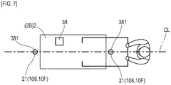
FIG. 7 is a top view of an installation cart in a second embodiment. - In the present invention, as an installation device for laying a magnetic marker in a road, in addition to a device which arranges the magnetic marker in the road, a device which performs a preparation operation and so forth for laying the magnetic marker may be used, the preparation operation including, for example, boring an accommodation hole of the magnetic marker or providing a mark for identifying a laying position on a road. Completion of magnetic-marker laying by the installation device for laying the magnetic marker in the road is not imperative. For example, even if magnetic-marker laying is not completed but operation of boring the accommodation hole is completed, the position of that accommodation hole is determined as the magnetic-marker laying position.
- Embodiments of the present invention are specifically described by using the following examples.
- The present embodiment is an example regarding an installation device of performing operation of laying
magnetic marker 10 in a road. Details of this are described by usingFIG. 1 to FIG. 6 . -
Installation cart 2 ofFIG. 1 is an installation device which provides a laying position for magnetic marker 10 (FIG. 2 ) in a road. Thisinstallation cart 2 boresaccommodation hole 108 for accommodatingmagnetic marker 10 inroad surface 100S, thereby determining the laying position formagnetic marker 10.Installation cart 2 includes one boring drill (one example of an operation unit) 21 forboring accommodation hole 108 at each of the front and rear ofvehicle body 2B. According to thisinstallation cart 2, accommodation holes 108 (laying positions) can be provided at two locations without moving. - Here,
magnetic marker 10 to be installed is a small-sized marker forming a columnar shape having a diameter of 20 mm and a height of 28 mm, as inFIG. 2 . A magnet formingmagnetic marker 10 is an isotropic ferrite plastic magnet formed by dispersing a magnetic powder of iron oxide as a magnetic material in a polymer material as a base material, and has a characteristic of a maximum energy product (BHmax)=6.4 kJ/m3. - The magnet of
magnetic marker 10 is a magnet with a magnetic flux density of the surface being 45 mT (millitesla) and the magnetic flux density reaching a height of 250 mm from the surface being on the order of 8 µT. The magnet as an isotropic ferrite plastic magnet has a magnetic material being iron oxide, and is thus resistant to corrosion and not required to be accommodated in a metal-made case or the like.Magnetic marker 10 can be directly accommodated and laid in a relatively small accommodation hole 108 (FIG. 1 ) having, for example, a diameter of 25 mm to 30 mm and a depth on the order of 35 mm to 40 mm. -
Installation cart 2 is, as inFIG. 1 , a four-wheel vehicle including twodriving wheels 281 at left and right on a front side ofvehicle body 2B and twofreewheels 282 at left and right on a rear side. Drivingwheels 281 at left and right on the front side can be individually driven, and can change the orientation ofinstallation cart 2 in accordance with the rotation difference. As forfreewheels 282 at left and right on the rear side, the direction of the wheels can be freely changed in accordance with the orientation ofinstallation cart 2. Note that the configuration of the wheels ofinstallation cart 2 may be a three-wheel configuration or a six-wheel configuration. - At the rear part of
vehicle body 2B ofinstallation cart 2,hand push handle 20 extending rearward overboring drill 21 on the rear side is provided. An operator can moveinstallation cart 2 by walking while pushinghand push handle 20.Hand push handle 20 is supported in a cantilever manner byoperation unit 201 including a sensor, not depicted, for sensing operation forces of both hands of the operator. In accordance with operation forces acting on thishand push handle 20, drivingwheels 281 are rotationally driven, thereby causing appropriate assist force. Thus, the operator can moveinstallation cart 2 with a relatively light force. Tooperation unit 201, a display panel (not depicted) is attached so as to allow the operator to perform visual inspection, and information such as a moving distance ofinstallation cart 2 is displayed. - On the front side of
vehicle body 2B,guide roller 280 is attached. With the use of thisguide roller 280, visual confirmation as to, for example, whethervehicle body 2B goes along a target line is facilitated. On the rear side ofvehicle body 2B,road counter roller 285 is attached for measuring a moving distance. -
Installation cart 2 includes, as inFIG. 1 , in addition to above-described front and rearboring drills 21,power generator 251 which uses light oil as a fuel, drivingcylinder 211 which drivesboring drills 21 in a vertical direction,suction cleaner 252 which collects dust such as cuttings and so forth.Boring drills 21 are driven by drivingcylinder 211 to advance and retreat in the vertical direction, but are not displaced in a horizontal direction in relation tovehicle body 2B. That is, the positions ofboring drills 21 in a horizontal plane alongroad surface 100S are constantly held in relation tovehicle body 2B. Front and rearboring drills 21 are positioned on center line CL (refer toFIG. 3 ) ofvehicle body 2B. Front and rearboring drills 21 are each 1 m away from center CP ofvehicle body 2B in the longitudinal direction (spans D1 and D2 are both 1 m) along center line CL. Therefore, a space between front andrear boring drills 21 ininstallation cart 2 is a span D=2 m. - Note that a relative position relation between front and rear boring drills 21 with respect to center CP of
vehicle body 2B is such that front-sideboring drill 21 is 1 m ahead of center CP ofvehicle body 2B and rear-sideboring drill 21 is 1 m behind center CP ofvehicle body 2B. Offset amounts (OF1 and OF2 inFIG. 1 andFIG. 3 ) representing this relative position relation are set in advance in arithmetic unit 30 (which will be described further below) forming one example of a position information acquisition unit as parameters indicating relative positions ofboring drills 21 with respect to center CP ofvehicle body 2B. -
Installation cart 2 includes, as inFIG. 4 , gyrocompass unit (azimuth information acquisition unit) 36 which measures the azimuth (orientation) of center line CL ofvehicle body 2B,encoder 37 which detects a rotation amount of above-described roadcounter roller 285, andarithmetic unit 30 which finds the boring position ofaccommodation hole 108 as the laying position formagnetic marker 10. -
Gyrocompass unit 36 is a measurement device which measures the azimuth of a measurement target with respect to true north as a reference azimuth. Thisgyrocompass unit 36 achieves the above-described measurement by using the gyro effect that the rotation axis of the gyroscope horizontally held on the surface of the rotating earth is along south to north. Ininstallation cart 2,gyrocompass unit 36 is set so that the azimuth of the measurement target is along center line CL of the vehicle body.Gyrocompass unit 36 measures the azimuth of center line CL ofvehicle body 2B with respect to true north as a reference azimuth, and inputs azimuth information indicating that azimuth toarithmetic unit 30. - Arithmetic unit 30 (
FIG. 4 ) includes an electronic circuit (not depicted) including a CPU (Central Processing Unit) which performs calculation processing, a ROM (Read Only Memory) and a RAM (Random Access Memory) which store parameters and so forth.Arithmetic unit 30 identifies the position (absolute position) ofinstallation cart 2 during laying operation by using inertial navigation, thereby performing arithmetic processing for identifying the boring position ofaccommodation hole 108 as a laying position. Position information of the laying position is stored indatabase 31 and accumulated as laying information ofmagnetic marker 10. -
Arithmetic unit 30 computes the moving distance and the relative position ofinstallation cart 2 based on the rotation amount inputted fromencoder 37, the azimuth of center line CL inputted fromgyrocompass unit 36 and so forth. The moving distance is computed by multiplying an integrated value of rotation amounts detected byencoder 37 by the diameter ofroad counter roller 285 or the like. The relative position can be computed by integrating instantaneous displacement amounts (moving distances) along the azimuth of center line CL measured bygyrocompass unit 36 after movement from the reference position with its absolute position identified in advance is started. Note in the present embodiment that center CP ofvehicle body 2B is set as a position-measurement location and this position is taken as the position ofinstallation cart 2. - Here, the operation of laying
magnetic marker 10 is performed by using, in addition toinstallation cart 2 ofFIG. 1 for boring accommodation holes 108, an installation cart (not depicted) which arrangesmagnetic markers 10 one by one inaccommodation holes 108, an installation cart (not depicted) which finishesroad surface 100S after arrangement ofmagnetic markers 10 and so forth. The installation cart for arrangement is an installation device to arrangemagnetic markers 10 inaccommodation holes 108 and supply a pavement material as an adhesive. The installation cart for finishing the road surface is an installation device which performs operation of cutting a superfluous pavement material swelling from the perimeter of the pavement material after curing the pavement material supplied toaccommodation holes 108 to smooth theroad surface 100S. - Next, details of the operation of installing
magnetic markers 10 by above-configuredinstallation cart 2 are described. - To perform the operation of laying
magnetic markers 10, as a preparation, marking line ML (refer toFIG. 5 ), which is a target line for layingmagnetic markers 10, is formed onroad surface 100S. Marking line ML can be formed by, for example, a vehicle equipped with a device dropping ink, paint, or the like for marking. If this vehicle is caused to travel along a traveling path such as a lane as an installation target, marking line ML, which is a target line for layingmagnetic markers 10, can be formed. - By the operator performing operation of pushing
installation cart 2 by hand along above-described marking line ML, the operation of boring accommodation holes 108 as laying positions formagnetic markers 10 can be performed. For example,installation cart 2 is preferably stopped every time the moving distance displayed by the above-described display panel is incremented by 10 m. If boring drills 21 and drivingcylinder 211 are operated at every stopping, as inFIG. 5 , layinglocations 10G can be provided with a span S2=10 m along marking line ML. Here, front and rear boring drills 21 and so forth are preferably each operated during stopping ofinstallation cart 2. In this case, without movement ofinstallation cart 2, accommodation holes 108 (layingpositions 10F) adjacent to each other with a span S1=2 m, which matches a span D betweenboring drills 21, can be formed at two locations forrespective laying location 10G. - To start movement of
installation cart 2 to providelaying locations 10G along the road, it is required to identify the initial position ofinstallation cart 2 in advance as a reference position. As a method of identifying this reference position, for example, there is a method of using a GPS device (not depicted) which measures an absolute position in advance by using a Global Positioning System (GPS). If the environment is such that GPS electric waves are receivable, by setting a GPS antenna at center CP (FIG. 1 andFIG. 3 ) ofvehicle body 2B, the absolute position of center CP ofvehicle body 2B can be measured, and this absolute position can be identified as a reference position. Also, for example, the reference position may be identified by measuring the absolute position of center CP ofvehicle body 2B by triangulation using surveying devices (not depicted) set at two locations with their absolute positions identified. - During movement of
installation cart 2, the computation of the relative position is repeatedly performed by taking the initial position with its absolute position identified as a reference position as described above.Arithmetic unit 30 integrates momentary displacement amounts based on the rotation amounts detected byencoder 37 along momentary azimuths of center line CL ofvehicle body 2B inputted fromgyrocompass unit 36, thereby computing the relative position ofinstallation cart 2 with respect to the reference position. - In
FIG. 6 , the relative position calculated byarithmetic unit 30 wheninstallation cart 2 performs laying operation at any layinglocation 10G is indicated by arrow V. By adding the relative position indicated by this arrow V to the reference position,arithmetic unit 30 identifies the absolute position of center CP forinstallation cart 2 while performing laying operation. - As described above, in
arithmetic unit 30, parameters indicating the arrangement ofboring drills 21 are set in advance, such as offset amounts (OF1=1 m, OF2=1 m inFIG. 6 ) ofboring drills 21 with respect to center CP ofvehicle body 2B.Arithmetic unit 30 performs computation of, as inFIG. 6 , shifting the position along the azimuth of center line CL ofvehicle body 2B measured bygyrocompass unit 36 by this offset amount. According to this computation, with reference to the position of center CP ofvehicle body 2B, the absolute positions of front and rear boring drills 21 can be identified. With the absolute position of eachboring drill 21 identified, the absolute positions ofaccommodation holes 108 at two locations, that is, the absolute positions of layingpositions 10F, can be identified. And, the position information of layingpositions 10F identified as described above is stored indatabase 31 connected toarithmetic unit 30 and accumulated as laying information ofmagnetic markers 10. - As described above,
installation cart 2 of the present embodiment can providelaying positions 10F formagnetic markers 10 at two locations without moving. A space forming the relative position relation between these layingpositions 10F at two locations matches the span D=2 m between front and rear boring drills 21 with high accuracy, and has a less possibility of varying for each layinglocation 10G. - According to
installation cart 2, layingpositions 10F at two locations adjacent to each other with a space of 2 m can be efficiently provided atrespective laying location 10G. To providelaying positions 10F at two locations adjacent to each other with a space of 2 m, it is not required to perform positioning, surveying, or the like ofinstallation cart 2 to achieve the space of 2 m with high accuracy. Therefore, by usinginstallation cart 2, layingpositions 10F at two locations can be efficiently provided atrespective laying locations 10G with high accuracy, and installation cost can be suppressed. - Also in the present embodiment, while laying
location 10G for every 10 m is provided by visual inspection or the like by the operator, the position ofinstallation cart 2 while performing laying operation is measured, thereby identifying the absolute position of layingposition 10F. According to this installation, it does not take time and effort such as measuring the position with high accuracy orpositioning installation cart 2 at a predetermined position with high accuracy. Thus, laying operation can be performed very efficiently. On the other hand, since the position ofinstallation cart 2 is measured while performing laying operation, highly-accurate position information can be acquired for each layingposition 10F. -
Installation cart 2 of the present embodiment does not assume position measurement by GPS, and thus can support environments such as the inside of a tunnel where GPS electric waves are not receivable. For example, in the case of a tunnel, the above-described reference position is preferably set by measuring the absolute position ofinstallation cart 2 at an entrance or exit where measurement of the absolute position by GPS can be performed. - While
installation cart 2 which includesboring drills 21 at the front and rear and is capable of boring accommodation holes 108 at two locations without moving has been exemplarily described, an installation cart with only oneboring drill 21 may be used. In this case, a plurality ofaccommodation holes 108 can be preferably bored by movingboring drill 21 in a horizontal plane alongroad surface 100S. Also, an installation cart including three or moreboring drills 21 may be used. In this case,boring drills 21 need not be arrayed on one straight line. Threeboring drills 21 may be provided so as to form, for example, a triangle. In this case, by identifying the azimuth of center line CL ofvehicle body 2B, the orientation of the triangle forming the arrangement shape of three laying positions bored by these threeboring drills 21 can be identified. The orientation of the triangle can be represented by a deviation angle with respect to the azimuth serving as a reference for, for example, any side of the triangle, a bisector equally dividing the angle of any apex, or the like. - In the present embodiment, the configuration has been exemplarily described in which position information indicating the absolute position of each laying
position 10F is stored indatabase 31 and accumulated as laying information ofmagnetic markers 10. In addition to the position information of each layingposition 10F, azimuth information indicating the orientation of a line segment (one example of an arrangement shape) connectinglaying positions 10F at two locations inrespective laying locations 10G may also be stored. Having a predetermined relation (a match in the present embodiment) with the azimuth of center line CL of installation cart 2 (vehicle body 2B) while performing laying operation, the azimuth of this line segment can be easily identified based on the azimuth of center line CL measured bygyrocompass unit 36. In operation of the road wheremagnetic markers 10 are laid, if the azimuth (orientation) of the line segment connectinglaying positions 10F at two locations is known, the traveling direction of a vehicle passing over these layingpositions 10F at two locations and so forth can be detected with high accuracy. - The present embodiment is an example in which a GPS unit forming one example of the position information acquisition unit is added to the installation cart of the first embodiment. Details of this are described with reference to
FIG. 7 . -
GPS unit 38 is, as inFIG. 7 , a unit which receives electric waves from a GPS satellite to measure its absolute position. ThisGPS unit 38 supports measurement by RTK (RealTime Kinematic)-GPS.GPS unit 38 performs a baseline analysis using a signal received by a fixed station with its absolute position identified, and this can identify a baseline vector from the fixed station toGPS unit 38 to measure the absolute position with high accuracy. - While
installation cart 2 of the present embodiment includes oneGPS unit 38 which measures the absolute position, thisGPS unit 38 has twoGPS antennas 381 connected thereto.GPS unit 38 measures absolute positions of the installation locations ofrespective GPS antennas 381. In the present embodiment, sinceGPS antennas 381 are respectively attached directly above front and rear boring drills 21, the position of eachboring drill 21 is a position-measurement location. As for thisinstallation cart 2, two absolute positions measured byGPS unit 38 are boring positions foraccommodation holes 108 and layingpositions 10F formagnetic markers 10. - With
installation cart 2 of the present embodiment, in a condition in which GPS electric waves are receivable, layingposition 10F formagnetic marker 10 can be identified by using GPS. In a condition in which the GPS electric waves reception condition is insufficient, as in the first embodiment, layingposition 10F formagnetic marker 10 can be identified by using inertial navigation . In this manner, by selectively using either of the method of identifying the laying position, the operation of layingmagnetic markers 10 including generation of laying information ofmagnetic markers 10 can be more efficiently performed irrespective of the condition. - Note that while the example has been described in which
GPS antennas 381 are respectively attached directly above twoboring drills 21 in the second embodiment,GPS antenna 381 may be attached directly above only either one of boring drills 21. In this case, based on the absolute position of oneboring drill 21 measured by the GPS, the absolute position of the otherboring drill 21 can be identified. For example, based on the absolute position of oneboring drill 21, the absolute position of the otherboring drill 21 may be identified by shifting the position along the azimuth of center line CL ofvehicle body 2B measured by gyrocompass unit. - Note that other configurations and operations and effects are similar to those of the first embodiment.
- In the foregoing, specific examples of the present invention are described in detail as in the embodiments, these specific examples merely disclose examples of technology included in the scope of claims for patent. Needless to say, the scope of claims for patent should not be restrictively construed based on the configuration, numerical values and so forth of the specific examples. The scope of claims for patent includes techniques acquired by variously modifying, changing, or combining as appropriate the above-described specific examples by using known techniques, knowledge of a person skilled in the art, and so forth.
-
- 10 magnetic marker
- 10F laying position
- 10G laying location
- 108 accommodation hole
- 2 installation cart (installation device)
- 2B vehicle body
- 20 hand push handle
- 21 boring drill (operation unit)
- 285 road counter roller
- 30 arithmetic unit (position information acquisition unit)
- 31 database
- 36 gyrocompass unit (azimuth information acquisition unit)
- 37 encoder
- 38 GPS unit (position information acquisition unit)
- 381 GPS antenna
Claims (4)
- An installation device for laying a magnetic marker in a road, comprising:an operation unit which provides a laying position for the magnetic marker, whereinthe installation device is capable of providing the laying position for the magnetic marker at each of a plurality of locations without moving, the plurality of locations having a predetermined relative position relation.
- The installation device in claim 1, wherein the installation device comprises a plurality of the operation units and, in the installation device, each of a plurality of the operation units is arranged for each of a plurality of the laying positions for a plurality of the magnetic markers at the plurality of locations.
- The installation device in claim 1 or 2, wherein the installation device is provided with a position-measurement location where a relative position relation with the operation unit is identified, and comprises a position information acquisition unit for acquiring position information of the position-measurement location.
- The installation device in any one of claims 1 to 3, further comprising an azimuth information acquisition unit which acquires azimuth information for identifying an orientation of an arrangement shape of the plurality of the laying positions for the plurality of the magnetic markers at the plurality of locations.
Applications Claiming Priority (2)
| Application Number | Priority Date | Filing Date | Title |
|---|---|---|---|
| JP2017237529A JP6920975B2 (en) | 2017-12-12 | 2017-12-12 | Construction equipment, construction method, and construction system |
| PCT/JP2018/045362 WO2019117098A1 (en) | 2017-12-12 | 2018-12-10 | Construction apparatus |
Publications (2)
| Publication Number | Publication Date |
|---|---|
| EP3725946A1 true EP3725946A1 (en) | 2020-10-21 |
| EP3725946A4 EP3725946A4 (en) | 2021-07-07 |
Family
ID=66820337
Family Applications (1)
| Application Number | Title | Priority Date | Filing Date |
|---|---|---|---|
| EP18888520.6A Withdrawn EP3725946A4 (en) | 2017-12-12 | 2018-12-10 | CONSTRUCTION DEVICE |
Country Status (6)
| Country | Link |
|---|---|
| US (1) | US11242659B2 (en) |
| EP (1) | EP3725946A4 (en) |
| JP (1) | JP6920975B2 (en) |
| CN (1) | CN111448351B (en) |
| SG (1) | SG11202005373WA (en) |
| WO (1) | WO2019117098A1 (en) |
Families Citing this family (4)
| Publication number | Priority date | Publication date | Assignee | Title |
|---|---|---|---|---|
| JP6965815B2 (en) * | 2018-04-12 | 2021-11-10 | 愛知製鋼株式会社 | Marker detection system and operation method of marker detection system |
| CN112921780A (en) * | 2021-03-02 | 2021-06-08 | 武汉理工大学 | Intelligent two-dimensional traffic marking spraying device |
| KR102393837B1 (en) * | 2021-09-13 | 2022-05-06 | 주식회사 정석케미칼 | Method for generating vehicle control signal based on magnetic paint lane and apparatus using the same |
| JP2025166459A (en) | 2024-04-24 | 2025-11-06 | 愛知製鋼株式会社 | Magnetic marker installation method and auxiliary tools for installation |
Family Cites Families (26)
| Publication number | Priority date | Publication date | Assignee | Title |
|---|---|---|---|---|
| DE1188112B (en) | 1960-09-10 | 1965-03-04 | Gino Eigenmann | Mobile device for the mechanical laying of at least one marking strip made of plastic on road surfaces and the like. like |
| FR2412652A1 (en) | 1977-12-20 | 1979-07-20 | Eigenmann Ludwig | Composite road surface marking line - comprises spaced sections each including prefabricated strip and sprayed hard-setting segments |
| DE3018693A1 (en) | 1980-05-16 | 1981-11-26 | H. Debuschewitz GmbH & Co KG, 5000 Köln | Cemented road marking studs laying machine - has appliances laying adhesive, and delivering and pressing studs all working together |
| AT391626B (en) * | 1988-04-25 | 1990-11-12 | Kniesel Ulrich | DEVICE FOR MOVING MARKING DOWELS FOR FLOOR MARKINGS OD. DGL. |
| JPH10181691A (en) * | 1996-12-24 | 1998-07-07 | Mitsubishi Heavy Ind Ltd | Fixed point holding control device |
| JP3520765B2 (en) | 1998-04-28 | 2004-04-19 | 株式会社デンソー | Lane change management system using vehicle guidance tags |
| JP2000212922A (en) * | 1999-01-22 | 2000-08-02 | Aichi Steel Works Ltd | Construction jig for magnetic marker |
| JP3564003B2 (en) * | 1999-06-15 | 2004-09-08 | 鹿島建設株式会社 | Construction method of lane marker for intelligent transportation system compatible road |
| JP3447048B2 (en) * | 2000-04-24 | 2003-09-16 | 鹿島道路株式会社 | Magnetic burying equipment |
| JP3747281B2 (en) | 2002-02-27 | 2006-02-22 | 株式会社竹中土木 | Wire excavation accuracy controller for ground improvement processing machine |
| JP2005202478A (en) | 2004-01-13 | 2005-07-28 | Denso Corp | Automated driving system for vehicles |
| JP2008025163A (en) * | 2006-07-20 | 2008-02-07 | Enzan Kobo:Kk | Drilling positioning control method for rock drill-equipped truck, and boom positioning control method for construction machinery |
| KR101133172B1 (en) | 2010-11-02 | 2012-04-06 | 한국철도기술연구원 | A heading estimation system and the method of driving vehicle using magnet marker position |
| US10301783B2 (en) | 2012-01-17 | 2019-05-28 | LimnTech LLC | Roadway maintenance striping control system |
| US20150294566A1 (en) * | 2014-04-15 | 2015-10-15 | Tomorrow's Transportation Today | Trip planning and management methods for an intelligent transit system with electronic guided buses |
| JP6583031B2 (en) * | 2016-02-10 | 2019-10-02 | 愛知製鋼株式会社 | Magnetic marker construction method and work vehicle |
| CN112609605A (en) * | 2016-02-10 | 2021-04-06 | 爱知制钢株式会社 | Roller body |
| JP6776547B2 (en) * | 2016-02-12 | 2020-10-28 | 愛知製鋼株式会社 | Construction method of magnetic marker |
| SG11201806864UA (en) * | 2016-02-16 | 2018-09-27 | Aichi Steel Corp | Work vehicle system and magnetic marker work method |
| SG11201809405RA (en) * | 2016-04-28 | 2018-11-29 | Aichi Steel Corp | Driving assistance system |
| WO2017209112A1 (en) * | 2016-06-03 | 2017-12-07 | 愛知製鋼株式会社 | Position capture method and system |
| CN105822226A (en) | 2016-06-08 | 2016-08-03 | 上海力阳道路加固科技股份有限公司 | Efficient road drilling car |
| EP3605487A4 (en) * | 2017-03-28 | 2020-10-07 | Aichi Steel Corporation | Marker system |
| JP7005943B2 (en) * | 2017-06-06 | 2022-01-24 | 愛知製鋼株式会社 | Marker system and operation method |
| DE102017215932B3 (en) * | 2017-09-11 | 2019-02-28 | Audi Ag | Method for determining position information of a motor vehicle and motor vehicle |
| JP7091668B2 (en) * | 2018-01-16 | 2022-06-28 | 愛知製鋼株式会社 | Driving support system |
-
2017
- 2017-12-12 JP JP2017237529A patent/JP6920975B2/en active Active
-
2018
- 2018-12-10 US US16/770,653 patent/US11242659B2/en active Active
- 2018-12-10 EP EP18888520.6A patent/EP3725946A4/en not_active Withdrawn
- 2018-12-10 CN CN201880079571.5A patent/CN111448351B/en active Active
- 2018-12-10 SG SG11202005373WA patent/SG11202005373WA/en unknown
- 2018-12-10 WO PCT/JP2018/045362 patent/WO2019117098A1/en not_active Ceased
Also Published As
| Publication number | Publication date |
|---|---|
| JP2019105067A (en) | 2019-06-27 |
| US20210172133A1 (en) | 2021-06-10 |
| WO2019117098A1 (en) | 2019-06-20 |
| US11242659B2 (en) | 2022-02-08 |
| EP3725946A4 (en) | 2021-07-07 |
| JP6920975B2 (en) | 2021-08-18 |
| CN111448351B (en) | 2021-12-21 |
| SG11202005373WA (en) | 2020-07-29 |
| CN111448351A (en) | 2020-07-24 |
Similar Documents
| Publication | Publication Date | Title |
|---|---|---|
| CN110402311B (en) | Construction method and operating system of magnetic marker | |
| US11242659B2 (en) | Installation device | |
| CN110419067B (en) | Marker system | |
| EP3725947B1 (en) | Marker installation method and marker installation system | |
| JP6828643B2 (en) | Position acquisition system and position acquisition method | |
| CN110709906B (en) | Marker system and application method | |
| JP6946695B2 (en) | Marker system | |
| CA2864903C (en) | Apparatus for aligning drilling machines | |
| JP7417132B2 (en) | How to generate map data | |
| US12602055B2 (en) | Vehicular system |
Legal Events
| Date | Code | Title | Description |
|---|---|---|---|
| STAA | Information on the status of an ep patent application or granted ep patent |
Free format text: STATUS: THE INTERNATIONAL PUBLICATION HAS BEEN MADE |
|
| PUAI | Public reference made under article 153(3) epc to a published international application that has entered the european phase |
Free format text: ORIGINAL CODE: 0009012 |
|
| STAA | Information on the status of an ep patent application or granted ep patent |
Free format text: STATUS: REQUEST FOR EXAMINATION WAS MADE |
|
| 17P | Request for examination filed |
Effective date: 20200605 |
|
| AK | Designated contracting states |
Kind code of ref document: A1 Designated state(s): AL AT BE BG CH CY CZ DE DK EE ES FI FR GB GR HR HU IE IS IT LI LT LU LV MC MK MT NL NO PL PT RO RS SE SI SK SM TR |
|
| AX | Request for extension of the european patent |
Extension state: BA ME |
|
| DAV | Request for validation of the european patent (deleted) | ||
| DAX | Request for extension of the european patent (deleted) | ||
| A4 | Supplementary search report drawn up and despatched |
Effective date: 20210608 |
|
| RIC1 | Information provided on ipc code assigned before grant |
Ipc: E01F 9/518 20160101AFI20210601BHEP Ipc: E01C 23/16 20060101ALI20210601BHEP Ipc: E01C 23/18 20060101ALI20210601BHEP Ipc: E01F 9/30 20160101ALI20210601BHEP Ipc: G05D 1/02 20200101ALI20210601BHEP |
|
| STAA | Information on the status of an ep patent application or granted ep patent |
Free format text: STATUS: EXAMINATION IS IN PROGRESS |
|
| 17Q | First examination report despatched |
Effective date: 20250819 |
|
| STAA | Information on the status of an ep patent application or granted ep patent |
Free format text: STATUS: THE APPLICATION HAS BEEN WITHDRAWN |
|
| 18W | Application withdrawn |
Effective date: 20251118 |