EP3725933A1 - Micro-bubble generator and laundry treatment device - Google Patents
Micro-bubble generator and laundry treatment device Download PDFInfo
- Publication number
- EP3725933A1 EP3725933A1 EP18939574.2A EP18939574A EP3725933A1 EP 3725933 A1 EP3725933 A1 EP 3725933A1 EP 18939574 A EP18939574 A EP 18939574A EP 3725933 A1 EP3725933 A1 EP 3725933A1
- Authority
- EP
- European Patent Office
- Prior art keywords
- air dissolving
- water
- air
- inlet
- outlet
- Prior art date
- Legal status (The legal status is an assumption and is not a legal conclusion. Google has not performed a legal analysis and makes no representation as to the accuracy of the status listed.)
- Granted
Links
Images

Classifications
-
- D—TEXTILES; PAPER
- D06—TREATMENT OF TEXTILES OR THE LIKE; LAUNDERING; FLEXIBLE MATERIALS NOT OTHERWISE PROVIDED FOR
- D06F—LAUNDERING, DRYING, IRONING, PRESSING OR FOLDING TEXTILE ARTICLES
- D06F35/00—Washing machines, apparatus, or methods not otherwise provided for
-
- D—TEXTILES; PAPER
- D06—TREATMENT OF TEXTILES OR THE LIKE; LAUNDERING; FLEXIBLE MATERIALS NOT OTHERWISE PROVIDED FOR
- D06F—LAUNDERING, DRYING, IRONING, PRESSING OR FOLDING TEXTILE ARTICLES
- D06F35/00—Washing machines, apparatus, or methods not otherwise provided for
- D06F35/002—Washing machines, apparatus, or methods not otherwise provided for using bubbles
-
- B—PERFORMING OPERATIONS; TRANSPORTING
- B01—PHYSICAL OR CHEMICAL PROCESSES OR APPARATUS IN GENERAL
- B01F—MIXING, e.g. DISSOLVING, EMULSIFYING OR DISPERSING
- B01F23/00—Mixing according to the phases to be mixed, e.g. dispersing or emulsifying
- B01F23/20—Mixing gases with liquids
- B01F23/23—Mixing gases with liquids by introducing gases into liquid media, e.g. for producing aerated liquids
- B01F23/231—Mixing gases with liquids by introducing gases into liquid media, e.g. for producing aerated liquids by bubbling
- B01F23/23105—Arrangement or manipulation of the gas bubbling devices
- B01F23/2311—Mounting the bubbling devices or the diffusers
-
- B—PERFORMING OPERATIONS; TRANSPORTING
- B01—PHYSICAL OR CHEMICAL PROCESSES OR APPARATUS IN GENERAL
- B01F—MIXING, e.g. DISSOLVING, EMULSIFYING OR DISPERSING
- B01F23/00—Mixing according to the phases to be mixed, e.g. dispersing or emulsifying
- B01F23/20—Mixing gases with liquids
- B01F23/23—Mixing gases with liquids by introducing gases into liquid media, e.g. for producing aerated liquids
- B01F23/232—Mixing gases with liquids by introducing gases into liquid media, e.g. for producing aerated liquids using flow-mixing means for introducing the gases, e.g. baffles
-
- B—PERFORMING OPERATIONS; TRANSPORTING
- B01—PHYSICAL OR CHEMICAL PROCESSES OR APPARATUS IN GENERAL
- B01F—MIXING, e.g. DISSOLVING, EMULSIFYING OR DISPERSING
- B01F23/00—Mixing according to the phases to be mixed, e.g. dispersing or emulsifying
- B01F23/20—Mixing gases with liquids
- B01F23/23—Mixing gases with liquids by introducing gases into liquid media, e.g. for producing aerated liquids
- B01F23/234—Surface aerating
-
- B—PERFORMING OPERATIONS; TRANSPORTING
- B01—PHYSICAL OR CHEMICAL PROCESSES OR APPARATUS IN GENERAL
- B01F—MIXING, e.g. DISSOLVING, EMULSIFYING OR DISPERSING
- B01F25/00—Flow mixers; Mixers for falling materials, e.g. solid particles
- B01F25/40—Static mixers
- B01F25/42—Static mixers in which the mixing is affected by moving the components jointly in changing directions, e.g. in tubes provided with baffles or obstructions
- B01F25/43—Mixing tubes, e.g. wherein the material is moved in a radial or partly reversed direction
- B01F25/433—Mixing tubes wherein the shape of the tube influences the mixing, e.g. mixing tubes with varying cross-section or provided with inwardly extending profiles
- B01F25/4335—Mixers with a converging-diverging cross-section
-
- B—PERFORMING OPERATIONS; TRANSPORTING
- B01—PHYSICAL OR CHEMICAL PROCESSES OR APPARATUS IN GENERAL
- B01F—MIXING, e.g. DISSOLVING, EMULSIFYING OR DISPERSING
- B01F25/00—Flow mixers; Mixers for falling materials, e.g. solid particles
- B01F25/40—Static mixers
- B01F25/42—Static mixers in which the mixing is affected by moving the components jointly in changing directions, e.g. in tubes provided with baffles or obstructions
- B01F25/43—Mixing tubes, e.g. wherein the material is moved in a radial or partly reversed direction
- B01F25/433—Mixing tubes wherein the shape of the tube influences the mixing, e.g. mixing tubes with varying cross-section or provided with inwardly extending profiles
- B01F25/4337—Mixers with a diverging-converging cross-section
-
- B—PERFORMING OPERATIONS; TRANSPORTING
- B01—PHYSICAL OR CHEMICAL PROCESSES OR APPARATUS IN GENERAL
- B01F—MIXING, e.g. DISSOLVING, EMULSIFYING OR DISPERSING
- B01F25/00—Flow mixers; Mixers for falling materials, e.g. solid particles
- B01F25/40—Static mixers
- B01F25/44—Mixers in which the components are pressed through slits
- B01F25/441—Mixers in which the components are pressed through slits characterised by the configuration of the surfaces forming the slits
- B01F25/4414—Mixers in which the components are pressed through slits characterised by the configuration of the surfaces forming the slits the slits being formed between the balls and the seats of a bearing-like construction
-
- B—PERFORMING OPERATIONS; TRANSPORTING
- B01—PHYSICAL OR CHEMICAL PROCESSES OR APPARATUS IN GENERAL
- B01F—MIXING, e.g. DISSOLVING, EMULSIFYING OR DISPERSING
- B01F25/00—Flow mixers; Mixers for falling materials, e.g. solid particles
- B01F25/40—Static mixers
- B01F25/45—Mixers in which the materials to be mixed are pressed together through orifices or interstitial spaces, e.g. between beads
- B01F25/452—Mixers in which the materials to be mixed are pressed together through orifices or interstitial spaces, e.g. between beads characterised by elements provided with orifices or interstitial spaces
- B01F25/4521—Mixers in which the materials to be mixed are pressed together through orifices or interstitial spaces, e.g. between beads characterised by elements provided with orifices or interstitial spaces the components being pressed through orifices in elements, e.g. flat plates or cylinders, which obstruct the whole diameter of the tube
-
- D—TEXTILES; PAPER
- D06—TREATMENT OF TEXTILES OR THE LIKE; LAUNDERING; FLEXIBLE MATERIALS NOT OTHERWISE PROVIDED FOR
- D06F—LAUNDERING, DRYING, IRONING, PRESSING OR FOLDING TEXTILE ARTICLES
- D06F39/00—Details of washing machines not specific to a single type of machines covered by groups D06F9/00 - D06F27/00
- D06F39/08—Liquid supply or discharge arrangements
-
- B—PERFORMING OPERATIONS; TRANSPORTING
- B01—PHYSICAL OR CHEMICAL PROCESSES OR APPARATUS IN GENERAL
- B01F—MIXING, e.g. DISSOLVING, EMULSIFYING OR DISPERSING
- B01F23/00—Mixing according to the phases to be mixed, e.g. dispersing or emulsifying
- B01F23/20—Mixing gases with liquids
- B01F23/23—Mixing gases with liquids by introducing gases into liquid media, e.g. for producing aerated liquids
- B01F23/231—Mixing gases with liquids by introducing gases into liquid media, e.g. for producing aerated liquids by bubbling
- B01F23/23105—Arrangement or manipulation of the gas bubbling devices
- B01F23/2311—Mounting the bubbling devices or the diffusers
- B01F23/23112—Mounting the bubbling devices or the diffusers comprising the use of flow guiding elements adjacent or above the gas stream
- B01F23/231121—Mounting the bubbling devices or the diffusers comprising the use of flow guiding elements adjacent or above the gas stream the flow guiding elements being baffles, tubes or walls
-
- B—PERFORMING OPERATIONS; TRANSPORTING
- B01—PHYSICAL OR CHEMICAL PROCESSES OR APPARATUS IN GENERAL
- B01F—MIXING, e.g. DISSOLVING, EMULSIFYING OR DISPERSING
- B01F23/00—Mixing according to the phases to be mixed, e.g. dispersing or emulsifying
- B01F23/20—Mixing gases with liquids
- B01F23/23—Mixing gases with liquids by introducing gases into liquid media, e.g. for producing aerated liquids
- B01F23/237—Mixing gases with liquids by introducing gases into liquid media, e.g. for producing aerated liquids characterised by the physical or chemical properties of gases or vapours introduced in the liquid media
- B01F23/2373—Mixing gases with liquids by introducing gases into liquid media, e.g. for producing aerated liquids characterised by the physical or chemical properties of gases or vapours introduced in the liquid media for obtaining fine bubbles, i.e. bubbles with a size below 100 µm
-
- D—TEXTILES; PAPER
- D06—TREATMENT OF TEXTILES OR THE LIKE; LAUNDERING; FLEXIBLE MATERIALS NOT OTHERWISE PROVIDED FOR
- D06F—LAUNDERING, DRYING, IRONING, PRESSING OR FOLDING TEXTILE ARTICLES
- D06F39/00—Details of washing machines not specific to a single type of machines covered by groups D06F9/00 - D06F27/00
- D06F39/08—Liquid supply or discharge arrangements
- D06F39/088—Liquid supply arrangements
Definitions
- the present application relates to the field of laundry treating devices, and more particularly to a microbubble generator and a laundry treating device.
- microbubble technology is mainly applied in the field of environmental protection, and also in households, such as skin care, showers, and a laundry treating device.
- Most of the current microbubble generators have complex structures, some are required to be provided with additional water pumps, and some are required to be controlled by a plurality of valves. Meanwhile, there are more restrictions on the way of feeding water, resulting in relatively high costs.
- the present invention seeks to solve at least one of the problems existing in the related art to at least some extent.
- the present application proposes a microbubble generator with a good bubble generating effect and a simple structure.
- the present invention further seeks to provide a laundry treating device having the microbubble generator.
- the microbubble generator includes: an air dissolving tank, defining an air dissolving cavity therein, and having an inlet and an outlet configured to allow water to flow in and out, the inlet and the outlet being staggered in a horizontal direction; a cavitator, provided outside the air dissolving tank and connected with the outlet, or provided at the outlet.
- microbubble generator with an ingenious structure, using a flow velocity difference between outflow water and inflow water of the air dissolving cavity and a height difference between the inlet and the outlet, a water seal is formed at the outlet, such that the pressure in the air dissolving cavity gradually rises to form a high-pressure cavity, thereby increasing the air dissolving amount.
- the microbubble generator has a simple structure, good air dissolving effects and low costs.
- the microbubble generator according to the embodiment of the present invention further includes: a baffle, provided in the air dissolving tank, at least partially located between the inlet and the outlet in the horizontal direction, and provided with a gap and/or a through hole.
- a width of the gap is less than or equal to 50 mm.
- a width of the gap ranges from 1 mm to 10 mm.
- a horizontal distance between the baffle and the outlet is greater than a horizontal distance between the baffle and the inlet.
- the horizontal distance between the baffle and the inlet is less than 50 mm.
- the inlet and the outlet are located at two ends of the air dissolving tank.
- a distance between the inlet and at least one side wall of the air dissolving cavity is less than 50 mm.
- a distance between the inlet and at least one side wall of the air dissolving cavity ranges from 1 mm to 20 mm.
- the air dissolving tank is provided with two air dissolving semi-casings fastened with each other, the inlet is provided in one of the air dissolving semi-casings and the outlet is provided in the other one of the air dissolving semi-casings.
- the two air dissolving semi-casings are in contact fit with each other at a joint by a step surface.
- an outer surface of the air dissolving tank is provided with reinforcing ribs arranged horizontally and vertically in a staggered manner.
- the microbubble generator is configured such that a flow velocity of outflow water is less than a flow velocity of inflow water when the air is dissolved.
- an upper portion of the air dissolving tank is provided with a water inlet pipe in communication with the top of the air dissolving cavity
- a lower portion of the air dissolving tank is provided with a water outlet pipe in communication with the bottom of the air dissolving cavity
- the water inlet pipe and the water outlet pipe are disposed horizontally.
- a laundry treating device is provided with the microbubble generator according to the above-mentioned embodiment of the present invention at a water inlet of the laundry treating device, and the microbubble generator is communicated with a water tub of the laundry treating device.
- the cost is low and the microbubble generating effect is good.
- a large number of microbubbles in washing water reduces the usage amount of washing powder or detergent, saves water and electricity resources, and reduces the residual washing powder or detergent on the laundry.
- microbubble generator 100 according to an embodiment of the present application will be described with reference to Figs. 1 to 8 .
- the microbubble generator 100 includes: an air dissolving tank 1 and a cavitator 2.
- the air dissolving tank 1 has an air dissolving cavity 10 defined therein, and an inlet 11 and an outlet 12 configured to feed and discharge water.
- the cavitator is provided outside the air dissolving tank 1 and connected with the outlet 12, or provided at the outlet 12.
- the cavitator 2 produces microbubbles from the gas dissolved in water using a cavitation effect.
- the microbubble generator 100 When the microbubble generator 100 is used, water soluble gas enters from air dissolving tank 1, and afterwards, the water containing air solute with a high concentration enters the cavitator 2.
- the cavitator 2 produces the microbubbles using the cavitation effect.
- the water flow discharged from the cavitator 2 contains a large number of microbubbles for various uses, such as washing.
- the inlet 11 of the air dissolving tank 1 is located above the outlet 12, and the inlet 11 and the outlet 12 are staggered in a horizontal direction.
- the microbubble generator 100 is configured such that a flow velocity of outflow water is less than a flow velocity of inflow water when the air is dissolved, i.e., the outflow water is less than the inflow water per unit time.
- the air dissolving cavity 10 finishes air dissolution by forming a water seal at the outlet 12.
- the water flow is injected to the air dissolving tank 1 from the inlet 11. Since the flow velocity of inflow water is greater than the flow velocity of outflow water, the water level in the air dissolving cavity 10 rises gradually after water is injected in the air dissolving tank 1 for a period of time. Due to the inlet 11 of the air dissolving tank 1 located above the outlet 12, the water level of the air dissolving cavity 10 would be over the outlet 12 when rising, such that a water seal is formed at the outlet 12, thereby forming a high-pressure cavity with the pressure in the air dissolving cavity 10 rising gradually.
- the pressure in an upper part of the air dissolving cavity 10 is raised gradually to form a high-pressure cavity, and a dissolvability of the air in the high-pressure state is greater than a dissolvability thereof in the low-pressure state, thus the dissolvability of air inside the air dissolving cavity 10 in water is increased greatly.
- a large amount of air is dissolved in the water flowing to the cavitator 2, such that the cavitator 2 may produce a large number of microbubbles.
- air is insoluble with respect to water.
- a percentage of the amount of air dissolved in water and the introduced amount of air is called as an air dissolving efficiency.
- the air dissolving efficiency is related to temperature, an air dissolving pressure, and a dynamic contact area of air and liquid phases.
- the method of changing the water temperature or air temperature is difficult to implement.
- the common method for improving the air dissolving efficiency is to use a booster pump to pressurize the air dissolving cavity 10, but various valves are required to be provided, so the cost of providing the booster pump is too high.
- the air-dissolving tank 1 dissolves air in water, which means that air is taken as a solute and dissolved in water, i.e., air is dispersed in water molecules in the form of ions. Air ions are dispersed in a state that air is dissolved, and the air ions in water molecules are relatively uniform. Afterwards, most of the bubbles precipitated by the cavitation effect only have a size of nanometers and micrometers at the beginning of formation. This is the desired microbubble produced by the microbubble generator 100.
- the microbubbles are dissolved with each other, and most of the obtained microbubbles may still be kept to be millimeter-sized or even less, with the best effect.
- the air dissolved in the water usually precipitates incompletely in the cavitator 2. In use, the air dissolved in the water will slowly replenish the microbubbles.
- the inlet 11 is located above the outlet 12, when introduced from the inlet 11, the water rushes to the water surface from above, causing the water surface to oscillate, and at the same time a part of high-pressure air is brought in, and a dynamic contact area of air and water may be increased.
- the inlet 11 and the outlet 12 are staggered in the horizontal direction, the flow path of the water flowing in the air dissolving cavity 10 is longer, which on the one hand, reduces the bubbles generated by the impact of the incoming water flow flowing from the outlet 12 due to being wrapped by the water flow, and on the other hand, increases the dissolution time and contact area of the excited bubbles in water.
- microbubble generator 100 In the microbubble generator 100 according to the embodiment of the present invention, neither power nor a plurality of valves is required, and the generation of microbubbles is implemented using a simple structure.
- microbubble generator 100 with an ingenious structure, using a flow velocity difference between outflow water and inflow water of the air dissolving cavity 10 and a height difference between the inlet 11 and the outlet 12, a water seal is formed at the outlet 12, such that the pressure in the air dissolving cavity gradually rises to form a high-pressure cavity, thereby increasing the air dissolving amount.
- the microbubble generator 100 has a simple structure, good air dissolving effects and low costs.
- the baffle 3 in the horizontal direction, is at least partially located between the inlet 11 and the outlet 12.
- the baffle 3 is provided with a gap 31 or a through hole, or both the gap 31 and the through hole.
- the baffle 3 is provided between the inlet 11 and the outlet 12, which intercepts the water flowing in from the inlet 11 towards the outlet 12.
- the gap 31 or through hole on the baffle 3 enables the water with air dissolved therein to flow through, but the bubbles caused by splash in the air dissolving cavity 10 are blocked. Large bubbles flow toward the cavitator 2, because the air in the air dissolving tank 1 would be wasted, resulting in the rapid decrease in air pressure of the air dissolving cavity 10 and influencing air dissolution. Moreover, after the large bubbles enter the cavitator 2, the cavitation effect would be affected.
- baffle 3 more splash may be formed when the water flow comes onto the baffle 3, and the baffle 3 may also be configured as a strengthening structure to enhance the pressure bearing ability of the air dissolving tank 1.
- the baffle 3 is at least partially located between the inlet 11 and the outlet 12 in the horizontal direction means that the baffle 3 may be completely located between the inlet 11 and the outlet 12 as shown in Fig. 2 , and the baffle 3 may also be merely partially located between the inlet 11 and the outlet 12.
- the baffle 3 may be formed as an arc-shaped plate or a spherical plate, and the baffle 3 is covered at the outlet 12. At this point, the baffle 3 is merely partially located between the inlet 11 and the outlet 12.
- the baffle 3 is formed as a flat plate and is vertically connected with the bottom wall of the air dissolving tank 1, which may not only prevent the bubbles generated by water flow excitation from flowing out of the air dissolving tank 1, but also facilitate the production and manufacture.
- the straight baffle 3 may be integrally formed on the air dissolving tank 1 or fixed to the air dissolving tank 1 in an inserting or welding manner much more easier.
- the baffle 3 may also be formed as an inclined plate, a double-layer hollow plate, or the above-mentioned curved plate, spherical plate, or the like.
- the gap 31 on the baffle 3 is formed in a strip shape in the vertical direction, which may also greatly improve the manufacturability of the microbubble generator 100. Only one gap 31 is shown in Fig. 5 .
- the baffle 3 may be formed as a grid plate with a plurality of gaps 31.
- the baffle 3 is configured as a perforated plate 29 having a plurality of through holes, or the baffle 3 is provided with both of the gap 31 and the through hole.
- a width of the gap 31 is less than or equal to 50 mm. It is appreciated that the width of the gap 31 on the baffle 3 is required to be relatively small, so as to prevent the bubbles formed by the water flow excitation from passing through the gap 31. Preferably, the width of the gap 31 ranges from 1 mm to 10 mm. Certainly, the size of the gap 31 may also be selected according to actual conditions, and is not limited to the above range.
- a horizontal distance between the baffle 3 and the outlet 12 is greater than a horizontal distance between the baffle 3 and the inlet 11, i.e., the baffle 3 is closer to the inlet 11 in the horizontal direction, thereby ensuring that the baffle 3 blocks the water bubbles excited by water flow and guaranteeing the air dissolving effect of the air dissolving tank 1.
- the horizontal distance between the baffle 3 and the inlet 11 is less than 50 mm.
- the air dissolving tank 1 may be formed into any shape, and the shape of the air dissolving tank 1 is not specifically limited herein. However, other parts of the air dissolving tank 1 may be provided to have good airtightness except for the outlet 12 in the air dissolution.
- the part of the air dissolving cavity 10 perpendicular to the inlet 11 has a small sectional area. It is appreciated that when water enters the air dissolving cavity 10, the incoming water flow would hit the inner wall and the water level of the air dissolving cavity 10. This phenomenon will produce more splash, and the generation of splash will help bring the water into the above high-pressure air, increasing the speed of air dissolving in the water.
- the part of the air dissolving cavity 10 perpendicular to the inlet 11 has the small sectional area, which contributes to the strong physical interaction between the splash generated when the water flow from the inlet 11 hit the water surface with the inner wall of the air dissolving cavity 10, such that the water may dissolve air rapidly.
- an inflow direction of the inlet 11 is downward vertically, and the incoming water flow enters the air dissolving cavity 10 in a vertical direction, which not only increases the splash, but also accelerates the air dissolving speed, and facilitates the manufacturability of mass production of the air dissolving tank 1.
- the inflow direction of the inlet 11 may also be inclined, i.e., the inflow direction of water may have an included angle with the vertical direction, so the incoming water blast area is very large.
- the inlet 11 and the outlet 12 are located at two ends of the air dissolving tank 1, such that the path of the water flow inside the air dissolving tank 1 is further lengthened and the bubbles generated by the water flow are further reduced to flow out of the outlet 12.
- the air dissolving cavity 10 has a square sectional area in the horizontal direction, and the inlet 11 and the outlet 12 are provided corresponding to the position with the longest straight-line distance at the two ends of the square.
- the air dissolving cavity 10 has a rectangular sectional area in the horizontal direction, and the inlet 11 and the outlet 12 are located at two ends of a long side of the rectangle.
- Such an air dissolving tank 1 is easy to process and easy to lay out during assembly.
- the sectional shape of the air dissolving cavity 10 may be any shape and is not limited to the rectangle, rhombus, or other irregular square shapes.
- the inlet 11 is located at the uppermost part of the air dissolving cavity 10, which may ensure that the incoming water flow arouses more splash and improve the air dissolving effect.
- the outlet 12 is located at the very bottom of the air dissolving cavity 10, such that the outlet 12 may form the water seal as soon as possible.
- a distance between the inlet 11 and at least one side wall of the air dissolving cavity 10 is less than 50 mm. That is, when the inlet 11 is in the working state, a distance between a projection to the water surface in the vertical direction and the inner wall surface of the at least one air dissolving cavity 10 is less than 50 mm. The water flow at the inlet 11 is more likely to hit the side wall of the air dissolving tank 1 to generate splash, thereby improving the air dissolving effect of the air dissolving tank 1.
- the distance between the inlet 11 and the at least one side wall of the air dissolving cavity 10 is between 1 mm and 20 mm.
- the inner wall of the air dissolving cavity 10 may be provided with a structure, such as an internal convex rib, which makes it easier to splash water.
- the air dissolving tank 1 is provided with two air dissolving semi-casings 13 fastened with each other.
- the inlet 11 is provided on one of the air dissolving semi-casings 13 and the outlet 12 is provided on the other of the air dissolving semi-casings 13.
- the inlet 11 and the outlet 12 are arranged on the two air dissolving semi-casings 13 respectively, which is easy to form, and the strength of each of the air dissolving semi-casings 13 is not too low.
- Such the air dissolving tank 1 has strong manufacturability, is convenient for mass production, and has low processing costs.
- the two air dissolving semi-casings 13 are connected by welding or gluing, so as to ensure the airtightness.
- the air dissolving tank 1 is configured as a plastic part.
- each of the air dissolving semi-casings 13 is an integrally injection-molded part.
- an upper portion of the air dissolving tank 1 is provided with a water inlet pipe 14 communicated with the top of air dissolving cavity 10
- a lower portion of the air dissolving tank 1 is provided with a water outlet pipe (not shown) in communication with the bottom of the air dissolving cavity 10, and the water inlet pipe 14 and the water outlet pipe are disposed horizontally, which facilitates assembly.
- the air dissolving tank 1 is mounted behind the detergent box, and the water inlet pipe 14 and the water outlet pipe are horizontally arranged to make assembly easier.
- the two air dissolving semi-casings 13 are arranged up and down, the water inlet pipe 14 is integrally formed on the upper air dissolving semi-casing 13, and the water outlet pipe 15 is integrally formed on the lower air dissolving semi-casing 13, which may guarantee the convenience and sealing performance.
- the two air dissolving semi-casings 13 are in contact fit with each other by a step surface 16 at a joint, which not only increases the contact area at the contact point of the two air dissolving semi-casings 13, but also increases the contact strength, such that at least part of the contact surface of the two air dissolving semi-casings 13 is perpendicular or nearly perpendicular to the pressure of the inner wall of the air dissolving cavity 10. Therefore, the two air dissolving semi-casings 13 will be pressed more and more tightly at the joint due to the high internal pressure, so as to avoid cracking and air leakage at the joint due to the high internal pressure.
- the outer surface of the air dissolving tank 1 is provided with reinforcing ribs 17 arranged horizontally and vertically in a staggered manner, which may increase the strength of the air dissolving tank 1 and avoid deformation and air leakage due to the high internal pressure.
- the cavitator 2 may adopt a structure of a known cavitation device in the prior art, e.g., an ultrasonic generator, or the like.
- the cavitator 2 includes a Venturi tube 28.
- the Venturi tube 28 is taken as the cavitator 2, without additional water pump, heating device or control valve 4, or the like, which greatly simplifies the structure of the cavitator 2 and reduces the production cost.
- the Venturi tube 28 does not have additional requirements on the way of water intake, such that the cavitator 2 may easily generate a large number of bubbles.
- the cavitator 2 is configured as an orifice plate 29 provided with a plurality of micro holes.
- the air dissolved in the water flow passing through the cavitator 2 may be relatively easily precipitated to form bubbles.
- each of the micro holes in the orifice plate 29 has a radius of 0.01 mm-10 mm. It has been proved through experiments that the orifice plate 29 with the above-mentioned parameters has better cavitation effects, and more bubbles may be generated.
- the specific parameters of the orifice plate 29 may be adjusted by the staff according to the actual working conditions, and are not limited to the above-mentioned range.
- the cavitator 2 includes a cavitation casing 23 and a cavitation ball 24.
- the cavitation casing 23 is provided therein with a water cavity 20, the water cavity 20 has a cavitation inlet 21 and a cavitation outlet 22 for water inflow and outflow, and the cavitation inlet 21 is connected with the outlet 12 of the air dissolving tank 1.
- the cavitation ball 24 is movably disposed in the water cavity 20, the water flowing in from the cavitation inlet 21 may push the cavitation ball 24 to block the cavitation outlet 22, and when the cavitation ball 24 is blocked at the cavitation outlet 22, the Venturi channel 25 is formed between the cavitation ball 24 and the inner wall of the water cavity 200.
- the Venturi channel 25 communicated with the cavitation outlet 22 is provided between the cavitation ball 24 and the inner wall of the water cavity 22. It is shown herein that the cavitation ball 24 does not completely block the cavitation outlet 22, but leaves the Venturi channel 25, such that the water flow with air dissolved in gradually flows out of the cavitation outlet 22.
- the movable cavitation ball 24 By setting the movable cavitation ball 24 in the water cavity 20 in front of the cavitation outlet 22, when the water flow with air dissolved in is continuously introduced through the cavitation inlet 21, the continuously introduced water flows along the inner wall of the water cavity 20, and pushes the cavitation ball 24 to move toward the cavitation outlet 22 after encountering the cavitation ball 24, such that the cavitation ball 24 moves to the front of the cavitation outlet 22 and gradually abuts against the cavitation outlet 22, forming the Venturi channel 25.
- the Venturi channel 25 corresponds to a Venturi tube and may produce the Venturi effect, such that air is precipitated from the solute state to form microbubbles. Moreover, the water flow keeps the cavitation ball 24 against the cavitation outlet 22, and the water flow with the gas solute dissolved in flows out of the Venturi channel 25 more quickly.
- the continuously introduced water flow is greater than the outgoing water flow, and the water cavity 20 is used as an air-tight cavity.
- the cavitation ball 24 abuts against the cavitation outlet 22, the internal pressure will increase to strengthen the cavitation effect.
- the adoption of such a cavitator 2 has not only low costs and low processing difficulty, but also advantages not available in other cavitation structures.
- the cavitation ball 24 is configured as a movable sphere. When the microbubble generator 100 stops working, the water flow decreases, and the cavitation ball 24 would leave the cavitation outlet 22 without the water flow, such that the remaining water in the microbubble generator 100 may be drained quickly, which on the one hand, facilitates the air to be pre-stored in the air dissolving tank 1, and on the other hand, avoids breeding too much bacteria due to the water deposit. In addition, such a cavitator 2 is also easy to clean.
- the microbubble generator 100 further includes an air valve provided on the air dissolving tank 1. It should be noted that when dissolving gradually, the air in the air dissolving tank 1 decreases gradually. With the air valve provided on the air dissolving tank 1, when the air in the air dissolving tank 1 reduces, the air valve is open, and the external air would enter the air dissolving tank 1, such that the air dissolving tank 1 is filled with sufficient air, which ensures that the microbubble generator 100 may increase air dissolving in the waterflow continuously.
- the water treated by the microbubble generator 100 according to the embodiment of the present invention contains a large number of microbubbles, and such microbubble water is taken as washing water, which may reduce the usage amount of washing powder or detergent, save water and electricity resources, and reduce the residual washing powder or detergent on the laundry.
- a water inlet of the laundry treating device is provided with the microbubble generator 100 according to the above-mentioned embodiment of the present invention, and the microbubble generator 100 guides the produced microbubble water to a water tub of the laundry treating device.
- the laundry treating device has low costs and good microbubble generating effects.
- a large number of microbubbles in washing water reduces the usage amount of washing powder or detergent, saves water and electricity resources, and reduces the residual washing powder or detergent on the laundry.
- the terms “mounted”, “connected”, “coupled” and “fixed” and the like are used broadly, and may be, for example, fixed connections, detachable connections, or integral connections; may also be mechanical or electrical connections; may also be direct connections or indirect connections via intervening structures; may also be inner communications or interactive relationship of two elements.
- the above terms can be appreciated by those skilled in the art according to specific situations.
- a structure in which a first feature is "on" or “below” a second feature may include an embodiment in which the first feature is in direct contact with the second feature, and may also include an embodiment in which the first feature and the second feature are contacted via an additional feature formed therebetween.
- a first feature "on,” “above,” or “on top of' a second feature may include an embodiment in which the first feature is right or obliquely “on,” “above,” or “on top of' the second feature, or just means that the first feature is at a height higher than that of the second feature; while a first feature "below,” “under,” or “on bottom of' a second feature may include an embodiment in which the first feature is right or obliquely “below,” “under,” or “on bottom of' the second feature, or just means that the first feature is at a height lower than that of the second feature.
Landscapes
- Chemical & Material Sciences (AREA)
- Chemical Kinetics & Catalysis (AREA)
- Engineering & Computer Science (AREA)
- Textile Engineering (AREA)
- Dispersion Chemistry (AREA)
- Detail Structures Of Washing Machines And Dryers (AREA)
- Accessory Of Washing/Drying Machine, Commercial Washing/Drying Machine, Other Washing/Drying Machine (AREA)
- Mixers With Rotating Receptacles And Mixers With Vibration Mechanisms (AREA)
Abstract
Description
- This application is based on and claims priority to Chinese Patent Applications Serial No.
201811308756. 7, filed on November 5, 2018 201821815922. 8, filed on November 5, 2018 - The present application relates to the field of laundry treating devices, and more particularly to a microbubble generator and a laundry treating device.
- At present, a microbubble technology is mainly applied in the field of environmental protection, and also in households, such as skin care, showers, and a laundry treating device. Most of the current microbubble generators have complex structures, some are required to be provided with additional water pumps, and some are required to be controlled by a plurality of valves. Meanwhile, there are more restrictions on the way of feeding water, resulting in relatively high costs.
- The present invention seeks to solve at least one of the problems existing in the related art to at least some extent. To this end, the present application proposes a microbubble generator with a good bubble generating effect and a simple structure.
- The present invention further seeks to provide a laundry treating device having the microbubble generator.
- The microbubble generator according to an embodiment of the present application includes: an air dissolving tank, defining an air dissolving cavity therein, and having an inlet and an outlet configured to allow water to flow in and out, the inlet and the outlet being staggered in a horizontal direction; a cavitator, provided outside the air dissolving tank and connected with the outlet, or provided at the outlet.
- In the microbubble generator according to the present invention, with an ingenious structure, using a flow velocity difference between outflow water and inflow water of the air dissolving cavity and a height difference between the inlet and the outlet, a water seal is formed at the outlet, such that the pressure in the air dissolving cavity gradually rises to form a high-pressure cavity, thereby increasing the air dissolving amount. The microbubble generator has a simple structure, good air dissolving effects and low costs.
- The microbubble generator according to the embodiment of the present invention further includes: a baffle, provided in the air dissolving tank, at least partially located between the inlet and the outlet in the horizontal direction, and provided with a gap and/or a through hole.
- In some embodiments, when the baffle is provided with the gap, a width of the gap is less than or equal to 50 mm.
- Optionally, when the baffle is provided with the gap, a width of the gap ranges from 1 mm to 10 mm.
- In some embodiments, a horizontal distance between the baffle and the outlet is greater than a horizontal distance between the baffle and the inlet.
- In some embodiments, the horizontal distance between the baffle and the inlet is less than 50 mm.
- In some embodiments, in the horizontal direction, the inlet and the outlet are located at two ends of the air dissolving tank.
- In some embodiments, a distance between the inlet and at least one side wall of the air dissolving cavity is less than 50 mm.
- Optionally, a distance between the inlet and at least one side wall of the air dissolving cavity ranges from 1 mm to 20 mm.
- In some embodiments, the air dissolving tank is provided with two air dissolving semi-casings fastened with each other, the inlet is provided in one of the air dissolving semi-casings and the outlet is provided in the other one of the air dissolving semi-casings.
- Specifically, the two air dissolving semi-casings are in contact fit with each other at a joint by a step surface.
- In some embodiments, an outer surface of the air dissolving tank is provided with reinforcing ribs arranged horizontally and vertically in a staggered manner.
- In some embodiments, the microbubble generator is configured such that a flow velocity of outflow water is less than a flow velocity of inflow water when the air is dissolved.
- In some embodiments, an upper portion of the air dissolving tank is provided with a water inlet pipe in communication with the top of the air dissolving cavity, a lower portion of the air dissolving tank is provided with a water outlet pipe in communication with the bottom of the air dissolving cavity, and the water inlet pipe and the water outlet pipe are disposed horizontally.
- A laundry treating device according to an embodiment of the present invention, is provided with the microbubble generator according to the above-mentioned embodiment of the present invention at a water inlet of the laundry treating device, and the microbubble generator is communicated with a water tub of the laundry treating device.
- In the laundry treating device according to the embodiment of the present invention, with the above-mentioned microbubble generator, the cost is low and the microbubble generating effect is good. A large number of microbubbles in washing water reduces the usage amount of washing powder or detergent, saves water and electricity resources, and reduces the residual washing powder or detergent on the laundry.
- Additional aspects and advantages the present application will be given in part in the following descriptions can be learned from the practice of the embodiments of the present disclosure.
-
-
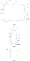
Fig. 1 is a schematic structural diagram of a microbubble generator according to an embodiment of the present application. -
Fig. 2 is a schematic sectional view of an air dissolving tank according to an embodiment of the present application. -
Fig. 3 is another schematic sectional view of an air dissolving tank according to an embodiment of the present application. -
Fig. 4 is a schematic sectional view of the air dissolving tank according to an embodiment of the present application. -
Fig. 5 is another schematic sectional view of the air dissolving tank according to an embodiment of the present application. -
Fig. 6 is a schematic structural diagram of a Venturi tube according to an embodiment of the present application. -
Fig. 7 is a schematic structural diagram of an orifice plate according to an embodiment of the present application. -
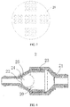
Fig. 8 is a schematic structural diagram of a cavitator according to an embodiment of the present application. -
-
microbubble generator 100, -
air dissolving tank 1,air dissolving cavity 10,inlet 11,outlet 12, air dissolving semi-casing 13,water inlet pipe 14,step surface 16, reinforcingrib 17, -
cavitator 2,water cavity 20,cavitation inlet 21,cavitation outlet 22,cavitation casing 23,cavitation ball 24, Venturichannel 25, Venturitube 28,orifice plate 29, - baffle 3,
gap 31. - Reference will be made in detail to embodiments of the present application. The examples of the embodiments are illustrated in the drawings. The same or similar elements and the elements having same or similar functions are denoted by like reference numerals throughout the descriptions. The embodiments described herein with reference to drawings are illustrative, and used to generally understand the present disclosure. The embodiments shall not be construed to limit the present application.
- The
microbubble generator 100 according to an embodiment of the present application will be described with reference toFigs. 1 to 8 . - As shown in
Figs. 1 and 2 , themicrobubble generator 100 according to an embodiment of the present application includes: anair dissolving tank 1 and acavitator 2. Theair dissolving tank 1 has anair dissolving cavity 10 defined therein, and aninlet 11 and anoutlet 12 configured to feed and discharge water. The cavitator is provided outside the air dissolvingtank 1 and connected with theoutlet 12, or provided at theoutlet 12. Thecavitator 2 produces microbubbles from the gas dissolved in water using a cavitation effect. - When the
microbubble generator 100 is used, water soluble gas enters from air dissolvingtank 1, and afterwards, the water containing air solute with a high concentration enters thecavitator 2. Thecavitator 2 produces the microbubbles using the cavitation effect. The water flow discharged from thecavitator 2 contains a large number of microbubbles for various uses, such as washing. - In the embodiment of the present invention, the
inlet 11 of the air dissolvingtank 1 is located above theoutlet 12, and theinlet 11 and theoutlet 12 are staggered in a horizontal direction. Moreover, themicrobubble generator 100 is configured such that a flow velocity of outflow water is less than a flow velocity of inflow water when the air is dissolved, i.e., the outflow water is less than the inflow water per unit time. Theair dissolving cavity 10 finishes air dissolution by forming a water seal at theoutlet 12. - Specifically, the water flow is injected to the
air dissolving tank 1 from theinlet 11. Since the flow velocity of inflow water is greater than the flow velocity of outflow water, the water level in theair dissolving cavity 10 rises gradually after water is injected in theair dissolving tank 1 for a period of time. Due to theinlet 11 of theair dissolving tank 1 located above theoutlet 12, the water level of theair dissolving cavity 10 would be over theoutlet 12 when rising, such that a water seal is formed at theoutlet 12, thereby forming a high-pressure cavity with the pressure in theair dissolving cavity 10 rising gradually. - It should be emphasized here that although the water seal is formed at the
outlet 12, water is still discharged from theoutlet 12 to thecavitator 2, but water is continuously introduced into theinlet 11. Therefore, the water level in theair dissolving cavity 10 is still rising continuously, which gradually reduces the air space above the water surface. When the air pressure in theair dissolving tank 1 gradually rises to the water pressure near the inlet water, the flow velocity of outflow water is equal to the flow velocity of inflow water. - Therefore, the pressure in an upper part of the
air dissolving cavity 10 is raised gradually to form a high-pressure cavity, and a dissolvability of the air in the high-pressure state is greater than a dissolvability thereof in the low-pressure state, thus the dissolvability of air inside theair dissolving cavity 10 in water is increased greatly. A large amount of air is dissolved in the water flowing to thecavitator 2, such that thecavitator 2 may produce a large number of microbubbles. - It should be noted that air is insoluble with respect to water. A percentage of the amount of air dissolved in water and the introduced amount of air is called as an air dissolving efficiency. The air dissolving efficiency is related to temperature, an air dissolving pressure, and a dynamic contact area of air and liquid phases. The method of changing the water temperature or air temperature is difficult to implement. The common method for improving the air dissolving efficiency is to use a booster pump to pressurize the
air dissolving cavity 10, but various valves are required to be provided, so the cost of providing the booster pump is too high. - In the prior art, there is also a solution in which double inlets are provided in the air dissolving device, one inlet configured to introduce water, and the other inlet configured to introduce air. In order to inject air into water, the booster pump is required to press the air into the water. In this solution, since the air inlet is located below the cavitator, the incoming bubbles will quickly flow toward the cavitator and be squeezed out. No space is available in the air dissolving tank for the bubbles to dissolve slowly, and the air dissolving effect is not ideal. The method of injecting air into the water by pressurizing is equivalent to directly pressing large bubbles into the water. Such large bubbles stay in water for a short period of time and are dissolved insufficiently. Even when passing through the cavitator, the large bubbles are squeezed into more small bubbles by the cavitator, but the small bubbles are millimeter-sized or greater, and will be quickly broken and released.
- It should be emphasized that in the embodiment of the present invention, it is proposed that the air-
dissolving tank 1 dissolves air in water, which means that air is taken as a solute and dissolved in water, i.e., air is dispersed in water molecules in the form of ions. Air ions are dispersed in a state that air is dissolved, and the air ions in water molecules are relatively uniform. Afterwards, most of the bubbles precipitated by the cavitation effect only have a size of nanometers and micrometers at the beginning of formation. This is the desired microbubble produced by themicrobubble generator 100. After the water with microbubbles flows to a final place for use, the microbubbles are dissolved with each other, and most of the obtained microbubbles may still be kept to be millimeter-sized or even less, with the best effect. The air dissolved in the water usually precipitates incompletely in thecavitator 2. In use, the air dissolved in the water will slowly replenish the microbubbles. - In the embodiment of the present invention, since the
inlet 11 is located above theoutlet 12, when introduced from theinlet 11, the water rushes to the water surface from above, causing the water surface to oscillate, and at the same time a part of high-pressure air is brought in, and a dynamic contact area of air and water may be increased. Moreover, since theinlet 11 and theoutlet 12 are staggered in the horizontal direction, the flow path of the water flowing in theair dissolving cavity 10 is longer, which on the one hand, reduces the bubbles generated by the impact of the incoming water flow flowing from theoutlet 12 due to being wrapped by the water flow, and on the other hand, increases the dissolution time and contact area of the excited bubbles in water. - In the
microbubble generator 100 according to the embodiment of the present invention, neither power nor a plurality of valves is required, and the generation of microbubbles is implemented using a simple structure. - In the
microbubble generator 100 according to the embodiment of the present invention, with an ingenious structure, using a flow velocity difference between outflow water and inflow water of theair dissolving cavity 10 and a height difference between theinlet 11 and theoutlet 12, a water seal is formed at theoutlet 12, such that the pressure in the air dissolving cavity gradually rises to form a high-pressure cavity, thereby increasing the air dissolving amount. Themicrobubble generator 100 has a simple structure, good air dissolving effects and low costs. - In the embodiment of the present invention, in the horizontal direction, the
baffle 3 is at least partially located between theinlet 11 and theoutlet 12. Thebaffle 3 is provided with agap 31 or a through hole, or both thegap 31 and the through hole. Thebaffle 3 is provided between theinlet 11 and theoutlet 12, which intercepts the water flowing in from theinlet 11 towards theoutlet 12. Thegap 31 or through hole on thebaffle 3 enables the water with air dissolved therein to flow through, but the bubbles caused by splash in theair dissolving cavity 10 are blocked. Large bubbles flow toward thecavitator 2, because the air in theair dissolving tank 1 would be wasted, resulting in the rapid decrease in air pressure of theair dissolving cavity 10 and influencing air dissolution. Moreover, after the large bubbles enter thecavitator 2, the cavitation effect would be affected. - Further, with the
baffle 3, more splash may be formed when the water flow comes onto thebaffle 3, and thebaffle 3 may also be configured as a strengthening structure to enhance the pressure bearing ability of theair dissolving tank 1. - The feature mentioned herein that the
baffle 3 is at least partially located between theinlet 11 and theoutlet 12 in the horizontal direction means that thebaffle 3 may be completely located between theinlet 11 and theoutlet 12 as shown inFig. 2 , and thebaffle 3 may also be merely partially located between theinlet 11 and theoutlet 12. For example, thebaffle 3 may be formed as an arc-shaped plate or a spherical plate, and thebaffle 3 is covered at theoutlet 12. At this point, thebaffle 3 is merely partially located between theinlet 11 and theoutlet 12. - In some embodiments, as shown in
Figs. 4 and 5 , thebaffle 3 is formed as a flat plate and is vertically connected with the bottom wall of theair dissolving tank 1, which may not only prevent the bubbles generated by water flow excitation from flowing out of theair dissolving tank 1, but also facilitate the production and manufacture. Compared with a curved plate, thestraight baffle 3 may be integrally formed on theair dissolving tank 1 or fixed to theair dissolving tank 1 in an inserting or welding manner much more easier. In other embodiments of the present invention, thebaffle 3 may also be formed as an inclined plate, a double-layer hollow plate, or the above-mentioned curved plate, spherical plate, or the like. - Specifically, as shown in
Fig. 5 , thegap 31 on thebaffle 3 is formed in a strip shape in the vertical direction, which may also greatly improve the manufacturability of themicrobubble generator 100. Only onegap 31 is shown inFig. 5 . In other embodiments, thebaffle 3 may be formed as a grid plate with a plurality ofgaps 31. - In other embodiments, the
baffle 3 is configured as aperforated plate 29 having a plurality of through holes, or thebaffle 3 is provided with both of thegap 31 and the through hole. - In some embodiments, when the
gap 31 is provided on thebaffle 3, a width of thegap 31 is less than or equal to 50 mm. It is appreciated that the width of thegap 31 on thebaffle 3 is required to be relatively small, so as to prevent the bubbles formed by the water flow excitation from passing through thegap 31. Preferably, the width of thegap 31 ranges from 1 mm to 10 mm. Certainly, the size of thegap 31 may also be selected according to actual conditions, and is not limited to the above range. - Optionally, a horizontal distance between the
baffle 3 and theoutlet 12 is greater than a horizontal distance between thebaffle 3 and theinlet 11, i.e., thebaffle 3 is closer to theinlet 11 in the horizontal direction, thereby ensuring that thebaffle 3 blocks the water bubbles excited by water flow and guaranteeing the air dissolving effect of theair dissolving tank 1. Preferably, the horizontal distance between thebaffle 3 and theinlet 11 is less than 50 mm. - It should be additionally noted that the
air dissolving tank 1 may be formed into any shape, and the shape of theair dissolving tank 1 is not specifically limited herein. However, other parts of theair dissolving tank 1 may be provided to have good airtightness except for theoutlet 12 in the air dissolution. - In some embodiments, as shown in
Figs. 3 and5 , the part of theair dissolving cavity 10 perpendicular to theinlet 11 has a small sectional area. It is appreciated that when water enters theair dissolving cavity 10, the incoming water flow would hit the inner wall and the water level of theair dissolving cavity 10. This phenomenon will produce more splash, and the generation of splash will help bring the water into the above high-pressure air, increasing the speed of air dissolving in the water. The part of theair dissolving cavity 10 perpendicular to theinlet 11 has the small sectional area, which contributes to the strong physical interaction between the splash generated when the water flow from theinlet 11 hit the water surface with the inner wall of theair dissolving cavity 10, such that the water may dissolve air rapidly. - In some optional embodiments, as shown in
Figs. 3 and5 , an inflow direction of theinlet 11 is downward vertically, and the incoming water flow enters theair dissolving cavity 10 in a vertical direction, which not only increases the splash, but also accelerates the air dissolving speed, and facilitates the manufacturability of mass production of theair dissolving tank 1. Certainly, in other embodiments of the present application, the inflow direction of theinlet 11 may also be inclined, i.e., the inflow direction of water may have an included angle with the vertical direction, so the incoming water blast area is very large. - In some embodiments, in the horizontal direction, as shown in
Figs. 2 and4 , theinlet 11 and theoutlet 12 are located at two ends of theair dissolving tank 1, such that the path of the water flow inside theair dissolving tank 1 is further lengthened and the bubbles generated by the water flow are further reduced to flow out of theoutlet 12. - The
air dissolving cavity 10 has a square sectional area in the horizontal direction, and theinlet 11 and theoutlet 12 are provided corresponding to the position with the longest straight-line distance at the two ends of the square. For example, theair dissolving cavity 10 has a rectangular sectional area in the horizontal direction, and theinlet 11 and theoutlet 12 are located at two ends of a long side of the rectangle. Such anair dissolving tank 1 is easy to process and easy to lay out during assembly. Certainly, in other embodiments of the present invention, the sectional shape of theair dissolving cavity 10 may be any shape and is not limited to the rectangle, rhombus, or other irregular square shapes. - Advantageously, as shown in
Figs. 2 and4 , theinlet 11 is located at the uppermost part of theair dissolving cavity 10, which may ensure that the incoming water flow arouses more splash and improve the air dissolving effect. Optionally, theoutlet 12 is located at the very bottom of theair dissolving cavity 10, such that theoutlet 12 may form the water seal as soon as possible. - In some embodiments, a distance between the
inlet 11 and at least one side wall of theair dissolving cavity 10 is less than 50 mm. That is, when theinlet 11 is in the working state, a distance between a projection to the water surface in the vertical direction and the inner wall surface of the at least oneair dissolving cavity 10 is less than 50 mm. The water flow at theinlet 11 is more likely to hit the side wall of theair dissolving tank 1 to generate splash, thereby improving the air dissolving effect of theair dissolving tank 1. Optionally, the distance between theinlet 11 and the at least one side wall of theair dissolving cavity 10 is between 1 mm and 20 mm. Certainly, in other embodiments of the present invention, the inner wall of theair dissolving cavity 10 may be provided with a structure, such as an internal convex rib, which makes it easier to splash water. - In some embodiments, as shown in
Figs. 2 to 5 , theair dissolving tank 1 is provided with two air dissolving semi-casings 13 fastened with each other. Theinlet 11 is provided on one of theair dissolving semi-casings 13 and theoutlet 12 is provided on the other of theair dissolving semi-casings 13. Theinlet 11 and theoutlet 12 are arranged on the two air dissolving semi-casings 13 respectively, which is easy to form, and the strength of each of theair dissolving semi-casings 13 is not too low. Such theair dissolving tank 1 has strong manufacturability, is convenient for mass production, and has low processing costs. - Optionally, the two air dissolving semi-casings 13 are connected by welding or gluing, so as to ensure the airtightness.
- Specifically, the
air dissolving tank 1 is configured as a plastic part. Optionally, each of theair dissolving semi-casings 13 is an integrally injection-molded part. - Further, as shown in
Figs. 1 to 5 , an upper portion of theair dissolving tank 1 is provided with awater inlet pipe 14 communicated with the top ofair dissolving cavity 10, a lower portion of theair dissolving tank 1 is provided with a water outlet pipe (not shown) in communication with the bottom of theair dissolving cavity 10, and thewater inlet pipe 14 and the water outlet pipe are disposed horizontally, which facilitates assembly. For example, when themicrobubble generator 100 is integrated with a detergent box, theair dissolving tank 1 is mounted behind the detergent box, and thewater inlet pipe 14 and the water outlet pipe are horizontally arranged to make assembly easier. - Advantageously, as shown in
Figs. 2 to 5 , the two air dissolving semi-casings 13 are arranged up and down, thewater inlet pipe 14 is integrally formed on the upperair dissolving semi-casing 13, and the water outlet pipe 15 is integrally formed on the lowerair dissolving semi-casing 13, which may guarantee the convenience and sealing performance. - Specifically, the two air dissolving semi-casings 13 are in contact fit with each other by a
step surface 16 at a joint, which not only increases the contact area at the contact point of the twoair dissolving semi-casings 13, but also increases the contact strength, such that at least part of the contact surface of the twoair dissolving semi-casings 13 is perpendicular or nearly perpendicular to the pressure of the inner wall of theair dissolving cavity 10. Therefore, the two air dissolving semi-casings 13 will be pressed more and more tightly at the joint due to the high internal pressure, so as to avoid cracking and air leakage at the joint due to the high internal pressure. - Further, the outer surface of the
air dissolving tank 1 is provided with reinforcingribs 17 arranged horizontally and vertically in a staggered manner, which may increase the strength of theair dissolving tank 1 and avoid deformation and air leakage due to the high internal pressure. - In the embodiment of the present application, the
cavitator 2 may adopt a structure of a known cavitation device in the prior art, e.g., an ultrasonic generator, or the like. - In some optional embodiments of the present invention, as shown in
Fig. 6 , thecavitator 2 includes aVenturi tube 28. Thus, it is possible to relatively easily precipitate the air dissolved in the water flow passing through thecavitator 2 and to produce bubbles. TheVenturi tube 28 is taken as thecavitator 2, without additional water pump, heating device or control valve 4, or the like, which greatly simplifies the structure of thecavitator 2 and reduces the production cost. TheVenturi tube 28 does not have additional requirements on the way of water intake, such that thecavitator 2 may easily generate a large number of bubbles. - In some other optional embodiments, as shown in
Fig. 7 , thecavitator 2 is configured as anorifice plate 29 provided with a plurality of micro holes. Thus, the air dissolved in the water flow passing through thecavitator 2 may be relatively easily precipitated to form bubbles. Specifically, each of the micro holes in theorifice plate 29 has a radius of 0.01 mm-10 mm. It has been proved through experiments that theorifice plate 29 with the above-mentioned parameters has better cavitation effects, and more bubbles may be generated. Certainly, the specific parameters of theorifice plate 29 may be adjusted by the staff according to the actual working conditions, and are not limited to the above-mentioned range. - In some further embodiments, as shown in
Fig. 8 , thecavitator 2 includes acavitation casing 23 and acavitation ball 24. Thecavitation casing 23 is provided therein with awater cavity 20, thewater cavity 20 has acavitation inlet 21 and acavitation outlet 22 for water inflow and outflow, and thecavitation inlet 21 is connected with theoutlet 12 of theair dissolving tank 1. Thecavitation ball 24 is movably disposed in thewater cavity 20, the water flowing in from thecavitation inlet 21 may push thecavitation ball 24 to block thecavitation outlet 22, and when thecavitation ball 24 is blocked at thecavitation outlet 22, theVenturi channel 25 is formed between thecavitation ball 24 and the inner wall of the water cavity 200. - When the
cavitation ball 24 is blocked at thecavitation outlet 22, theVenturi channel 25 communicated with thecavitation outlet 22 is provided between thecavitation ball 24 and the inner wall of thewater cavity 22. It is shown herein that thecavitation ball 24 does not completely block thecavitation outlet 22, but leaves theVenturi channel 25, such that the water flow with air dissolved in gradually flows out of thecavitation outlet 22. - By setting the
movable cavitation ball 24 in thewater cavity 20 in front of thecavitation outlet 22, when the water flow with air dissolved in is continuously introduced through thecavitation inlet 21, the continuously introduced water flows along the inner wall of thewater cavity 20, and pushes thecavitation ball 24 to move toward thecavitation outlet 22 after encountering thecavitation ball 24, such that thecavitation ball 24 moves to the front of thecavitation outlet 22 and gradually abuts against thecavitation outlet 22, forming theVenturi channel 25. - When the water with the air solute dissolved in flows through the
Venturi channel 25, the open area will decrease and then increase. As the open area decreases and the flow velocity of the water with gas solute increases, the pressure decreases. As the open area increases and the flow velocity of the gas solute decreases, the pressure increases. TheVenturi channel 25 corresponds to a Venturi tube and may produce the Venturi effect, such that air is precipitated from the solute state to form microbubbles. Moreover, the water flow keeps thecavitation ball 24 against thecavitation outlet 22, and the water flow with the gas solute dissolved in flows out of theVenturi channel 25 more quickly. - In this process, the continuously introduced water flow is greater than the outgoing water flow, and the
water cavity 20 is used as an air-tight cavity. When thecavitation ball 24 abuts against thecavitation outlet 22, the internal pressure will increase to strengthen the cavitation effect. - The adoption of such a
cavitator 2 has not only low costs and low processing difficulty, but also advantages not available in other cavitation structures. Thecavitation ball 24 is configured as a movable sphere. When themicrobubble generator 100 stops working, the water flow decreases, and thecavitation ball 24 would leave thecavitation outlet 22 without the water flow, such that the remaining water in themicrobubble generator 100 may be drained quickly, which on the one hand, facilitates the air to be pre-stored in theair dissolving tank 1, and on the other hand, avoids breeding too much bacteria due to the water deposit. In addition, such acavitator 2 is also easy to clean. - In some embodiments, the
microbubble generator 100 further includes an air valve provided on theair dissolving tank 1. It should be noted that when dissolving gradually, the air in theair dissolving tank 1 decreases gradually. With the air valve provided on theair dissolving tank 1, when the air in theair dissolving tank 1 reduces, the air valve is open, and the external air would enter theair dissolving tank 1, such that theair dissolving tank 1 is filled with sufficient air, which ensures that themicrobubble generator 100 may increase air dissolving in the waterflow continuously. - The water treated by the
microbubble generator 100 according to the embodiment of the present invention contains a large number of microbubbles, and such microbubble water is taken as washing water, which may reduce the usage amount of washing powder or detergent, save water and electricity resources, and reduce the residual washing powder or detergent on the laundry. - In a laundry treating device according to the embodiment of the present invention, a water inlet of the laundry treating device is provided with the
microbubble generator 100 according to the above-mentioned embodiment of the present invention, and themicrobubble generator 100 guides the produced microbubble water to a water tub of the laundry treating device. - With the above-mentioned
microbubble generator 100, the laundry treating device according to the embodiment of the present invention has low costs and good microbubble generating effects. A large number of microbubbles in washing water reduces the usage amount of washing powder or detergent, saves water and electricity resources, and reduces the residual washing powder or detergent on the laundry. - Other components of the laundry treating device according to the embodiment of the present application, such as a motor, an impeller, a drum, or the like, and their operations are well known to persons skilled in the art, and not described in detail herein.
- In the description of the present application, it is appreciated that terms such as "center", "length", "upper", "lower", "vertical", "horizontal", "top", "bottom", "inner", and "outer" should be construed to refer to the orientation as then described or as shown in the drawings under discussion. These relative terms are for convenience of description and do not require that the present application be constructed or operated in a particular orientation, thus cannot be construed to limit the present application. In the description of the present invention, "a plurality of" means two or more unless otherwise stated.
- In the present invention, unless specified or limited otherwise, the terms "mounted", "connected", "coupled" and "fixed" and the like are used broadly, and may be, for example, fixed connections, detachable connections, or integral connections; may also be mechanical or electrical connections; may also be direct connections or indirect connections via intervening structures; may also be inner communications or interactive relationship of two elements. The above terms can be appreciated by those skilled in the art according to specific situations.
- In the present invention, unless specified or limited otherwise, a structure in which a first feature is "on" or "below" a second feature may include an embodiment in which the first feature is in direct contact with the second feature, and may also include an embodiment in which the first feature and the second feature are contacted via an additional feature formed therebetween. Furthermore, a first feature "on," "above," or "on top of' a second feature may include an embodiment in which the first feature is right or obliquely "on," "above," or "on top of' the second feature, or just means that the first feature is at a height higher than that of the second feature; while a first feature "below," "under," or "on bottom of' a second feature may include an embodiment in which the first feature is right or obliquely "below," "under," or "on bottom of' the second feature, or just means that the first feature is at a height lower than that of the second feature.
- In the description of the present specification, reference throughout this specification to "an embodiment", "some embodiments", "example", "specific example" or "some examples" means that a particular feature, structure, material, or characteristic described in connection with the embodiment or example is included in at least one embodiment or example of the present invention. In the specification, the schematic expressions to the above-mentioned terms are not necessarily referring to the same embodiment or example. Furthermore, the described particular features, structures, materials, or characteristics may be combined in any suitable manner in one or more embodiments or examples. Furthermore, those skilled in the art may combine different embodiments or examples and different embodiments or features in the examples described in the specification, without mutual contradictions.
- Although embodiments of the present invention have been shown and illustrated, it shall be appreciated that the above-mentioned embodiments are exemplary and not construed as limitations to the present invention. Various changes, modifications, alternatives and variants within the scope of the present invention may be made by those skilled in the art.
Claims (15)
- A microbubble generator, comprising:an air dissolving tank, defining an air dissolving cavity therein, and having an inlet and an outlet configured to allow water to flow in and out, the inlet and the outlet being staggered in a horizontal direction;a cavitator, provided outside the air dissolving tank and connected with the outlet, or provided at the outlet.
- The microbubble generator according to claim 1, further comprising: a baffle, provided in the air dissolving tank, at least partially located between the inlet and the outlet in the horizontal direction, and provided with a gap and/or a through hole.
- The microbubble generator according to claim 2, wherein when the baffle is provided with the gap, a width of the gap is less than or equal to 50 mm.
- The microbubble generator according to claim 3, when the baffle is provided with the gap, the width of the gap ranges from 1 mm to 10 mm.
- The microbubble generator according to any one of claims 2 to 4, wherein a horizontal distance between the baffle and the outlet is greater than a horizontal distance between the baffle and the inlet.
- The microbubble generator according to claim 5, wherein the horizontal distance between the baffle and the inlet is less than 50 mm.
- The microbubble generator according to any one of claims 1 to 6, wherein in the horizontal direction, the inlet and the outlet are located at two ends of the air dissolving tank.
- The microbubble generator according to any one of claims 1 to 7, wherein a distance between the inlet and at least one side wall of the air dissolving cavity is less than 50 mm.
- The microbubble generator according to claim 8, wherein the distance between the inlet and the at least one side wall of the air dissolving cavity ranges from 1 mm to 20 mm.
- The microbubble generator according to any one of claims 1 to 9, wherein the air dissolving tank is provided with two air dissolving semi-casings fastened with each other, the inlet is provided in one of the air dissolving semi-casings and the outlet is provided in the other one of the air dissolving semi-casings.
- The microbubble generator according to claim 10, wherein the two air dissolving semi-casings are in contact fit with each other at a joint by a step surface.
- The microbubble generator according to any one of claims 1 to 11, wherein an outer surface of the air dissolving tank is provided with reinforcing ribs arranged horizontally and vertically in a staggered manner.
- The microbubble generator according to any one of claims 1 to 12, wherein the microbubble generator is configured such that a flow velocity of outflow water is less than a flow velocity of inflow water when the air is dissolved.
- The microbubble generator according to any one of claims 1 to 13, wherein an upper portion of the air dissolving tank is provided with a water inlet pipe in communication with the top of the air dissolving cavity, a lower portion of the air dissolving tank is provided with a water outlet pipe in communication with the bottom of the air dissolving cavity, and the water inlet pipe and the water outlet pipe are disposed horizontally.
- A laundry treating device, provided with the microbubble generator according to any one of claims 1 to 14 at a water inlet of the laundry treating device, the microbubble generator being communicated with a water tub of the laundry treating device.
Applications Claiming Priority (3)
| Application Number | Priority Date | Filing Date | Title |
|---|---|---|---|
| CN201811308756.7A CN111206378B (en) | 2018-11-05 | 2018-11-05 | Microbubble generator and clothing treating device |
| CN201821815922.8U CN209353112U (en) | 2018-11-05 | 2018-11-05 | Microbubble generator and clothing processing apparatus |
| PCT/CN2018/121187 WO2020093522A1 (en) | 2018-11-05 | 2018-12-14 | Micro-bubble generator and laundry treatment device |
Publications (4)
| Publication Number | Publication Date |
|---|---|
| EP3725933A1 true EP3725933A1 (en) | 2020-10-21 |
| EP3725933A4 EP3725933A4 (en) | 2021-06-09 |
| EP3725933C0 EP3725933C0 (en) | 2023-08-23 |
| EP3725933B1 EP3725933B1 (en) | 2023-08-23 |
Family
ID=70611680
Family Applications (1)
| Application Number | Title | Priority Date | Filing Date |
|---|---|---|---|
| EP18939574.2A Active EP3725933B1 (en) | 2018-11-05 | 2018-12-14 | Micro-bubble generator and laundry treatment device |
Country Status (5)
| Country | Link |
|---|---|
| US (1) | US20210071338A1 (en) |
| EP (1) | EP3725933B1 (en) |
| JP (1) | JP7204876B2 (en) |
| RU (1) | RU2761802C1 (en) |
| WO (1) | WO2020093522A1 (en) |
Families Citing this family (1)
| Publication number | Priority date | Publication date | Assignee | Title |
|---|---|---|---|---|
| TR2023019522A1 (en) * | 2023-12-29 | 2025-07-21 | Arcelik As | A SYSTEM AND A METHOD FOR DISSOLVING A CLEANING AGENT IN A LIQUID SOLVENT |
Family Cites Families (24)
| Publication number | Priority date | Publication date | Assignee | Title |
|---|---|---|---|---|
| US4629559A (en) * | 1985-06-12 | 1986-12-16 | Envirex Inc. | Vertical looped reactor tank with delayed air release feature |
| JP2792016B2 (en) * | 1994-05-31 | 1998-08-27 | 和泉電気株式会社 | Gas-liquid dissolving and mixing equipment |
| JP2974236B2 (en) * | 1994-09-30 | 1999-11-10 | 和泉電気株式会社 | Gas-liquid dissolution mixing method and apparatus |
| JP3765759B2 (en) * | 2002-02-04 | 2006-04-12 | 株式会社 多自然テクノワークス | Microbubble generator |
| CN100537007C (en) * | 2004-05-31 | 2009-09-09 | 三洋设备产业株式会社 | Method and device for producing fine air bubble-containing liquid, and fine air bubble producer assembled in the device |
| JP2008161734A (en) * | 2006-12-26 | 2008-07-17 | Ngk Insulators Ltd | Functional water making apparatus and functional water making method using it |
| JP5010550B2 (en) * | 2008-07-28 | 2012-08-29 | 株式会社 ケネックス | Bubble generator |
| JP2010115594A (en) * | 2008-11-13 | 2010-05-27 | Nsi:Kk | Fine bubble generation method, fine bubble generator, and reduced water |
| JP2012040448A (en) * | 2008-11-14 | 2012-03-01 | Yasutaka Sakamoto | Microbubble generator |
| JP5001320B2 (en) * | 2009-03-26 | 2012-08-15 | パナソニック株式会社 | Gas dissolving device |
| JP4563496B1 (en) * | 2009-10-22 | 2010-10-13 | 株式会社H&S | Microbubble generator |
| KR101284266B1 (en) * | 2011-07-15 | 2013-07-08 | 한국기계연구원 | Device for generating micro and/or nano bubble based on circulation unit with high solubility of water |
| CN101941765A (en) * | 2010-07-23 | 2011-01-12 | 东北电力大学 | Flotation and sedimentation solid-liquid separation device |
| KR101618150B1 (en) * | 2011-02-15 | 2016-05-19 | 삼성전자 주식회사 | Bubble generaint apparatus and washing machine having the same |
| JP5878344B2 (en) * | 2011-11-25 | 2016-03-08 | 株式会社ガスター | PRESSURE CONTAINER AND AIR SOLUTION DEVICE USING THE PRESSURE CONTAINER |
| CN102583616A (en) * | 2012-02-20 | 2012-07-18 | 无锡工源机械有限公司 | Gas-liquid equilibrium dissolved air vessel |
| CN102755846A (en) * | 2012-07-28 | 2012-10-31 | 甘肃金桥给水排水设计与工程(集团)有限公司 | Micro-bubble dissolved air generation device |
| CN105986400A (en) * | 2015-02-13 | 2016-10-05 | 青岛海尔洗衣机有限公司 | Washing machine provided with ultra-fine bubble generating device |
| CN105110446B (en) * | 2015-08-20 | 2017-12-19 | 苏州香山红叶环境技术有限公司 | Nano bubble hydrogen production water machine |
| MY185562A (en) * | 2015-12-25 | 2021-05-20 | Toshiba Lifestyle Products & Services Corp | Washing machine |
| JP2018086628A (en) * | 2016-11-29 | 2018-06-07 | 日鉄鉱業株式会社 | Air flow classifier |
| KR102397435B1 (en) * | 2017-03-23 | 2022-05-12 | 주식회사 위니아전자 | Washing machine and method for suppling for washing water including micro-bubble |
| KR102397439B1 (en) * | 2017-03-23 | 2022-05-12 | 주식회사 위니아전자 | Washing machine, generator for micro-bubble thereof and method for suppling for washing water including micro-bubble |
| CN207362525U (en) * | 2017-10-17 | 2018-05-15 | 无锡小天鹅股份有限公司 | Microbubble generator and device for clothing processing |
-
2018
- 2018-12-14 RU RU2020142899A patent/RU2761802C1/en active
- 2018-12-14 EP EP18939574.2A patent/EP3725933B1/en active Active
- 2018-12-14 US US16/970,954 patent/US20210071338A1/en not_active Abandoned
- 2018-12-14 JP JP2021502589A patent/JP7204876B2/en active Active
- 2018-12-14 WO PCT/CN2018/121187 patent/WO2020093522A1/en not_active Ceased
Also Published As
| Publication number | Publication date |
|---|---|
| JP7204876B2 (en) | 2023-01-16 |
| US20210071338A1 (en) | 2021-03-11 |
| JP2021529658A (en) | 2021-11-04 |
| WO2020093522A1 (en) | 2020-05-14 |
| RU2761802C1 (en) | 2021-12-13 |
| EP3725933C0 (en) | 2023-08-23 |
| EP3725933A4 (en) | 2021-06-09 |
| EP3725933B1 (en) | 2023-08-23 |
Similar Documents
| Publication | Publication Date | Title |
|---|---|---|
| CN209353112U (en) | Microbubble generator and clothing processing apparatus | |
| CN111206384B (en) | Clothes treatment device | |
| CN109663516B (en) | Microbubble generating circulation system and clothes treatment device | |
| EP3725933B1 (en) | Micro-bubble generator and laundry treatment device | |
| EP3725932B1 (en) | Microbubble generator and clothes treatment device | |
| CN209952609U (en) | Microbubble generator and washing device | |
| CN209952610U (en) | Microbubble generator and washing device | |
| CN209958090U (en) | Feeding device and clothes treatment equipment | |
| CN209958076U (en) | Clothes treating device | |
| CN111206378B (en) | Microbubble generator and clothing treating device | |
| CN209958074U (en) | Microbubble generator and clothing processing apparatus | |
| CN207493515U (en) | A kind of micro-nano bubble generator | |
| CN209952608U (en) | Microbubble generator and washing device | |
| CN111206379B (en) | Microbubble generator and clothing treating device | |
| CN111659273B (en) | Microbubble generator and washing device | |
| CN109667105B (en) | Microbubble generation circulation system | |
| CN111659274B (en) | Microbubble generator and washing device | |
| CN111636173A (en) | Clothes treating device | |
| WO2020177346A1 (en) | Dispensing apparatus and clothing treatment device | |
| WO2020177314A1 (en) | Microbubble generator and washing device | |
| KR200425758Y1 (en) | Micro Bubble Bath | |
| WO2020177313A1 (en) | Microbubble generator and washing device | |
| CN217378299U (en) | Washing machine water route, washing machine | |
| CN111636176A (en) | Delivery device and laundry treatment equipment | |
| WO2020103380A1 (en) | Laundry treatment device |
Legal Events
| Date | Code | Title | Description |
|---|---|---|---|
| STAA | Information on the status of an ep patent application or granted ep patent |
Free format text: STATUS: THE INTERNATIONAL PUBLICATION HAS BEEN MADE |
|
| PUAI | Public reference made under article 153(3) epc to a published international application that has entered the european phase |
Free format text: ORIGINAL CODE: 0009012 |
|
| STAA | Information on the status of an ep patent application or granted ep patent |
Free format text: STATUS: REQUEST FOR EXAMINATION WAS MADE |
|
| 17P | Request for examination filed |
Effective date: 20200715 |
|
| AK | Designated contracting states |
Kind code of ref document: A1 Designated state(s): AL AT BE BG CH CY CZ DE DK EE ES FI FR GB GR HR HU IE IS IT LI LT LU LV MC MK MT NL NO PL PT RO RS SE SI SK SM TR |
|
| AX | Request for extension of the european patent |
Extension state: BA ME |
|
| A4 | Supplementary search report drawn up and despatched |
Effective date: 20210511 |
|
| RIC1 | Information provided on ipc code assigned before grant |
Ipc: D06F 35/00 20060101AFI20210504BHEP Ipc: D06F 39/08 20060101ALI20210504BHEP Ipc: B01F 3/04 20060101ALI20210504BHEP |
|
| DAV | Request for validation of the european patent (deleted) | ||
| DAX | Request for extension of the european patent (deleted) | ||
| GRAP | Despatch of communication of intention to grant a patent |
Free format text: ORIGINAL CODE: EPIDOSNIGR1 |
|
| STAA | Information on the status of an ep patent application or granted ep patent |
Free format text: STATUS: GRANT OF PATENT IS INTENDED |
|
| RIC1 | Information provided on ipc code assigned before grant |
Ipc: D06F 39/08 20060101ALN20230217BHEP Ipc: B01F 25/452 20220101ALI20230217BHEP Ipc: B01F 25/441 20220101ALI20230217BHEP Ipc: B01F 25/433 20220101ALI20230217BHEP Ipc: B01F 23/234 20220101ALI20230217BHEP Ipc: B01F 23/232 20220101ALI20230217BHEP Ipc: D06F 35/00 20060101AFI20230217BHEP |
|
| INTG | Intention to grant announced |
Effective date: 20230324 |
|
| GRAS | Grant fee paid |
Free format text: ORIGINAL CODE: EPIDOSNIGR3 |
|
| GRAA | (expected) grant |
Free format text: ORIGINAL CODE: 0009210 |
|
| STAA | Information on the status of an ep patent application or granted ep patent |
Free format text: STATUS: THE PATENT HAS BEEN GRANTED |
|
| AK | Designated contracting states |
Kind code of ref document: B1 Designated state(s): AL AT BE BG CH CY CZ DE DK EE ES FI FR GB GR HR HU IE IS IT LI LT LU LV MC MK MT NL NO PL PT RO RS SE SI SK SM TR |
|
| REG | Reference to a national code |
Ref country code: GB Ref legal event code: FG4D |
|
| REG | Reference to a national code |
Ref country code: CH Ref legal event code: EP |
|
| REG | Reference to a national code |
Ref country code: DE Ref legal event code: R096 Ref document number: 602018056236 Country of ref document: DE |
|
| REG | Reference to a national code |
Ref country code: IE Ref legal event code: FG4D |
|
| U01 | Request for unitary effect filed |
Effective date: 20230912 |
|
| U07 | Unitary effect registered |
Designated state(s): AT BE BG DE DK EE FI FR IT LT LU LV MT NL PT SE SI Effective date: 20230918 |
|
| PG25 | Lapsed in a contracting state [announced via postgrant information from national office to epo] |
Ref country code: GR Free format text: LAPSE BECAUSE OF FAILURE TO SUBMIT A TRANSLATION OF THE DESCRIPTION OR TO PAY THE FEE WITHIN THE PRESCRIBED TIME-LIMIT Effective date: 20231124 |
|
| PG25 | Lapsed in a contracting state [announced via postgrant information from national office to epo] |
Ref country code: IS Free format text: LAPSE BECAUSE OF FAILURE TO SUBMIT A TRANSLATION OF THE DESCRIPTION OR TO PAY THE FEE WITHIN THE PRESCRIBED TIME-LIMIT Effective date: 20231223 |
|
| U20 | Renewal fee for the european patent with unitary effect paid |
Year of fee payment: 6 Effective date: 20231215 |
|
| PG25 | Lapsed in a contracting state [announced via postgrant information from national office to epo] |
Ref country code: RS Free format text: LAPSE BECAUSE OF FAILURE TO SUBMIT A TRANSLATION OF THE DESCRIPTION OR TO PAY THE FEE WITHIN THE PRESCRIBED TIME-LIMIT Effective date: 20230823 Ref country code: NO Free format text: LAPSE BECAUSE OF FAILURE TO SUBMIT A TRANSLATION OF THE DESCRIPTION OR TO PAY THE FEE WITHIN THE PRESCRIBED TIME-LIMIT Effective date: 20231123 Ref country code: IS Free format text: LAPSE BECAUSE OF FAILURE TO SUBMIT A TRANSLATION OF THE DESCRIPTION OR TO PAY THE FEE WITHIN THE PRESCRIBED TIME-LIMIT Effective date: 20231223 Ref country code: HR Free format text: LAPSE BECAUSE OF FAILURE TO SUBMIT A TRANSLATION OF THE DESCRIPTION OR TO PAY THE FEE WITHIN THE PRESCRIBED TIME-LIMIT Effective date: 20230823 Ref country code: GR Free format text: LAPSE BECAUSE OF FAILURE TO SUBMIT A TRANSLATION OF THE DESCRIPTION OR TO PAY THE FEE WITHIN THE PRESCRIBED TIME-LIMIT Effective date: 20231124 |
|
| PG25 | Lapsed in a contracting state [announced via postgrant information from national office to epo] |
Ref country code: PL Free format text: LAPSE BECAUSE OF FAILURE TO SUBMIT A TRANSLATION OF THE DESCRIPTION OR TO PAY THE FEE WITHIN THE PRESCRIBED TIME-LIMIT Effective date: 20230823 |
|
| PG25 | Lapsed in a contracting state [announced via postgrant information from national office to epo] |
Ref country code: ES Free format text: LAPSE BECAUSE OF FAILURE TO SUBMIT A TRANSLATION OF THE DESCRIPTION OR TO PAY THE FEE WITHIN THE PRESCRIBED TIME-LIMIT Effective date: 20230823 |
|
| PG25 | Lapsed in a contracting state [announced via postgrant information from national office to epo] |
Ref country code: SM Free format text: LAPSE BECAUSE OF FAILURE TO SUBMIT A TRANSLATION OF THE DESCRIPTION OR TO PAY THE FEE WITHIN THE PRESCRIBED TIME-LIMIT Effective date: 20230823 Ref country code: RO Free format text: LAPSE BECAUSE OF FAILURE TO SUBMIT A TRANSLATION OF THE DESCRIPTION OR TO PAY THE FEE WITHIN THE PRESCRIBED TIME-LIMIT Effective date: 20230823 Ref country code: ES Free format text: LAPSE BECAUSE OF FAILURE TO SUBMIT A TRANSLATION OF THE DESCRIPTION OR TO PAY THE FEE WITHIN THE PRESCRIBED TIME-LIMIT Effective date: 20230823 Ref country code: CZ Free format text: LAPSE BECAUSE OF FAILURE TO SUBMIT A TRANSLATION OF THE DESCRIPTION OR TO PAY THE FEE WITHIN THE PRESCRIBED TIME-LIMIT Effective date: 20230823 Ref country code: SK Free format text: LAPSE BECAUSE OF FAILURE TO SUBMIT A TRANSLATION OF THE DESCRIPTION OR TO PAY THE FEE WITHIN THE PRESCRIBED TIME-LIMIT Effective date: 20230823 |
|
| REG | Reference to a national code |
Ref country code: DE Ref legal event code: R097 Ref document number: 602018056236 Country of ref document: DE |
|
| PLBE | No opposition filed within time limit |
Free format text: ORIGINAL CODE: 0009261 |
|
| STAA | Information on the status of an ep patent application or granted ep patent |
Free format text: STATUS: NO OPPOSITION FILED WITHIN TIME LIMIT |
|
| 26N | No opposition filed |
Effective date: 20240524 |
|
| REG | Reference to a national code |
Ref country code: CH Ref legal event code: PL |
|
| PG25 | Lapsed in a contracting state [announced via postgrant information from national office to epo] |
Ref country code: MC Free format text: LAPSE BECAUSE OF FAILURE TO SUBMIT A TRANSLATION OF THE DESCRIPTION OR TO PAY THE FEE WITHIN THE PRESCRIBED TIME-LIMIT Effective date: 20230823 |
|
| GBPC | Gb: european patent ceased through non-payment of renewal fee |
Effective date: 20231214 |
|
| PG25 | Lapsed in a contracting state [announced via postgrant information from national office to epo] |
Ref country code: MC Free format text: LAPSE BECAUSE OF FAILURE TO SUBMIT A TRANSLATION OF THE DESCRIPTION OR TO PAY THE FEE WITHIN THE PRESCRIBED TIME-LIMIT Effective date: 20230823 |
|
| REG | Reference to a national code |
Ref country code: IE Ref legal event code: MM4A |
|
| PG25 | Lapsed in a contracting state [announced via postgrant information from national office to epo] |
Ref country code: IE Free format text: LAPSE BECAUSE OF NON-PAYMENT OF DUE FEES Effective date: 20231214 |
|
| PG25 | Lapsed in a contracting state [announced via postgrant information from national office to epo] |
Ref country code: GB Free format text: LAPSE BECAUSE OF NON-PAYMENT OF DUE FEES Effective date: 20231214 |
|
| PG25 | Lapsed in a contracting state [announced via postgrant information from national office to epo] |
Ref country code: CH Free format text: LAPSE BECAUSE OF NON-PAYMENT OF DUE FEES Effective date: 20231231 |
|
| PG25 | Lapsed in a contracting state [announced via postgrant information from national office to epo] |
Ref country code: IE Free format text: LAPSE BECAUSE OF NON-PAYMENT OF DUE FEES Effective date: 20231214 Ref country code: GB Free format text: LAPSE BECAUSE OF NON-PAYMENT OF DUE FEES Effective date: 20231214 Ref country code: CH Free format text: LAPSE BECAUSE OF NON-PAYMENT OF DUE FEES Effective date: 20231231 |
|
| U20 | Renewal fee for the european patent with unitary effect paid |
Year of fee payment: 7 Effective date: 20241213 |
|
| PG25 | Lapsed in a contracting state [announced via postgrant information from national office to epo] |
Ref country code: CY Free format text: LAPSE BECAUSE OF FAILURE TO SUBMIT A TRANSLATION OF THE DESCRIPTION OR TO PAY THE FEE WITHIN THE PRESCRIBED TIME-LIMIT; INVALID AB INITIO Effective date: 20181214 |
|
| PG25 | Lapsed in a contracting state [announced via postgrant information from national office to epo] |
Ref country code: HU Free format text: LAPSE BECAUSE OF FAILURE TO SUBMIT A TRANSLATION OF THE DESCRIPTION OR TO PAY THE FEE WITHIN THE PRESCRIBED TIME-LIMIT; INVALID AB INITIO Effective date: 20181214 |
|
| PG25 | Lapsed in a contracting state [announced via postgrant information from national office to epo] |
Ref country code: TR Free format text: LAPSE BECAUSE OF FAILURE TO SUBMIT A TRANSLATION OF THE DESCRIPTION OR TO PAY THE FEE WITHIN THE PRESCRIBED TIME-LIMIT Effective date: 20230823 |
|
| U20 | Renewal fee for the european patent with unitary effect paid |
Year of fee payment: 8 Effective date: 20251217 |
|
| U1N | Appointed representative for the unitary patent procedure changed after the registration of the unitary effect |
Representative=s name: TREEBY, PHILIP DAVID WILLIAM; GB |