EP3725625B1 - Method and device for controlling hybrid vehicle - Google Patents
Method and device for controlling hybrid vehicle Download PDFInfo
- Publication number
- EP3725625B1 EP3725625B1 EP17934928.7A EP17934928A EP3725625B1 EP 3725625 B1 EP3725625 B1 EP 3725625B1 EP 17934928 A EP17934928 A EP 17934928A EP 3725625 B1 EP3725625 B1 EP 3725625B1
- Authority
- EP
- European Patent Office
- Prior art keywords
- rotational speed
- failure
- internal combustion
- combustion engine
- engine
- Prior art date
- Legal status (The legal status is an assumption and is not a legal conclusion. Google has not performed a legal analysis and makes no representation as to the accuracy of the status listed.)
- Active
Links
Images


Classifications
-
- B—PERFORMING OPERATIONS; TRANSPORTING
- B60—VEHICLES IN GENERAL
- B60W—CONJOINT CONTROL OF VEHICLE SUB-UNITS OF DIFFERENT TYPE OR DIFFERENT FUNCTION; CONTROL SYSTEMS SPECIALLY ADAPTED FOR HYBRID VEHICLES; ROAD VEHICLE DRIVE CONTROL SYSTEMS FOR PURPOSES NOT RELATED TO THE CONTROL OF A PARTICULAR SUB-UNIT
- B60W20/00—Control systems specially adapted for hybrid vehicles
- B60W20/10—Controlling the power contribution of each of the prime movers to meet required power demand
- B60W20/15—Control strategies specially adapted for achieving a particular effect
-
- B—PERFORMING OPERATIONS; TRANSPORTING
- B60—VEHICLES IN GENERAL
- B60K—ARRANGEMENT OR MOUNTING OF PROPULSION UNITS OR OF TRANSMISSIONS IN VEHICLES; ARRANGEMENT OR MOUNTING OF PLURAL DIVERSE PRIME-MOVERS IN VEHICLES; AUXILIARY DRIVES FOR VEHICLES; INSTRUMENTATION OR DASHBOARDS FOR VEHICLES; ARRANGEMENTS IN CONNECTION WITH COOLING, AIR INTAKE, GAS EXHAUST OR FUEL SUPPLY OF PROPULSION UNITS IN VEHICLES
- B60K6/00—Arrangement or mounting of plural diverse prime-movers for mutual or common propulsion, e.g. hybrid propulsion systems comprising electric motors and internal combustion engines
- B60K6/20—Arrangement or mounting of plural diverse prime-movers for mutual or common propulsion, e.g. hybrid propulsion systems comprising electric motors and internal combustion engines the prime-movers consisting of electric motors and internal combustion engines, e.g. HEVs
- B60K6/42—Arrangement or mounting of plural diverse prime-movers for mutual or common propulsion, e.g. hybrid propulsion systems comprising electric motors and internal combustion engines the prime-movers consisting of electric motors and internal combustion engines, e.g. HEVs characterised by the architecture of the hybrid electric vehicle
- B60K6/46—Series type
-
- B—PERFORMING OPERATIONS; TRANSPORTING
- B60—VEHICLES IN GENERAL
- B60W—CONJOINT CONTROL OF VEHICLE SUB-UNITS OF DIFFERENT TYPE OR DIFFERENT FUNCTION; CONTROL SYSTEMS SPECIALLY ADAPTED FOR HYBRID VEHICLES; ROAD VEHICLE DRIVE CONTROL SYSTEMS FOR PURPOSES NOT RELATED TO THE CONTROL OF A PARTICULAR SUB-UNIT
- B60W20/00—Control systems specially adapted for hybrid vehicles
- B60W20/50—Control strategies for responding to system failures, e.g. for fault diagnosis, failsafe operation or limp mode
-
- B—PERFORMING OPERATIONS; TRANSPORTING
- B60—VEHICLES IN GENERAL
- B60W—CONJOINT CONTROL OF VEHICLE SUB-UNITS OF DIFFERENT TYPE OR DIFFERENT FUNCTION; CONTROL SYSTEMS SPECIALLY ADAPTED FOR HYBRID VEHICLES; ROAD VEHICLE DRIVE CONTROL SYSTEMS FOR PURPOSES NOT RELATED TO THE CONTROL OF A PARTICULAR SUB-UNIT
- B60W10/00—Conjoint control of vehicle sub-units of different type or different function
- B60W10/04—Conjoint control of vehicle sub-units of different type or different function including control of propulsion units
- B60W10/06—Conjoint control of vehicle sub-units of different type or different function including control of propulsion units including control of combustion engines
-
- B—PERFORMING OPERATIONS; TRANSPORTING
- B60—VEHICLES IN GENERAL
- B60W—CONJOINT CONTROL OF VEHICLE SUB-UNITS OF DIFFERENT TYPE OR DIFFERENT FUNCTION; CONTROL SYSTEMS SPECIALLY ADAPTED FOR HYBRID VEHICLES; ROAD VEHICLE DRIVE CONTROL SYSTEMS FOR PURPOSES NOT RELATED TO THE CONTROL OF A PARTICULAR SUB-UNIT
- B60W10/00—Conjoint control of vehicle sub-units of different type or different function
- B60W10/04—Conjoint control of vehicle sub-units of different type or different function including control of propulsion units
- B60W10/08—Conjoint control of vehicle sub-units of different type or different function including control of propulsion units including control of electric propulsion units, e.g. motors or generators
-
- F—MECHANICAL ENGINEERING; LIGHTING; HEATING; WEAPONS; BLASTING
- F02—COMBUSTION ENGINES; HOT-GAS OR COMBUSTION-PRODUCT ENGINE PLANTS
- F02D—CONTROLLING COMBUSTION ENGINES
- F02D41/00—Electrical control of supply of combustible mixture or its constituents
- F02D41/02—Circuit arrangements for generating control signals
- F02D41/04—Introducing corrections for particular operating conditions
- F02D41/045—Detection of accelerating or decelerating state
-
- F—MECHANICAL ENGINEERING; LIGHTING; HEATING; WEAPONS; BLASTING
- F02—COMBUSTION ENGINES; HOT-GAS OR COMBUSTION-PRODUCT ENGINE PLANTS
- F02D—CONTROLLING COMBUSTION ENGINES
- F02D41/00—Electrical control of supply of combustible mixture or its constituents
- F02D41/22—Safety or indicating devices for abnormal conditions
-
- B—PERFORMING OPERATIONS; TRANSPORTING
- B60—VEHICLES IN GENERAL
- B60W—CONJOINT CONTROL OF VEHICLE SUB-UNITS OF DIFFERENT TYPE OR DIFFERENT FUNCTION; CONTROL SYSTEMS SPECIALLY ADAPTED FOR HYBRID VEHICLES; ROAD VEHICLE DRIVE CONTROL SYSTEMS FOR PURPOSES NOT RELATED TO THE CONTROL OF A PARTICULAR SUB-UNIT
- B60W2510/00—Input parameters relating to a particular sub-units
- B60W2510/06—Combustion engines, Gas turbines
- B60W2510/0638—Engine speed
-
- B—PERFORMING OPERATIONS; TRANSPORTING
- B60—VEHICLES IN GENERAL
- B60W—CONJOINT CONTROL OF VEHICLE SUB-UNITS OF DIFFERENT TYPE OR DIFFERENT FUNCTION; CONTROL SYSTEMS SPECIALLY ADAPTED FOR HYBRID VEHICLES; ROAD VEHICLE DRIVE CONTROL SYSTEMS FOR PURPOSES NOT RELATED TO THE CONTROL OF A PARTICULAR SUB-UNIT
- B60W2510/00—Input parameters relating to a particular sub-units
- B60W2510/08—Electric propulsion units
- B60W2510/081—Speed
-
- B—PERFORMING OPERATIONS; TRANSPORTING
- B60—VEHICLES IN GENERAL
- B60W—CONJOINT CONTROL OF VEHICLE SUB-UNITS OF DIFFERENT TYPE OR DIFFERENT FUNCTION; CONTROL SYSTEMS SPECIALLY ADAPTED FOR HYBRID VEHICLES; ROAD VEHICLE DRIVE CONTROL SYSTEMS FOR PURPOSES NOT RELATED TO THE CONTROL OF A PARTICULAR SUB-UNIT
- B60W2540/00—Input parameters relating to occupants
- B60W2540/10—Accelerator pedal position
-
- B—PERFORMING OPERATIONS; TRANSPORTING
- B60—VEHICLES IN GENERAL
- B60W—CONJOINT CONTROL OF VEHICLE SUB-UNITS OF DIFFERENT TYPE OR DIFFERENT FUNCTION; CONTROL SYSTEMS SPECIALLY ADAPTED FOR HYBRID VEHICLES; ROAD VEHICLE DRIVE CONTROL SYSTEMS FOR PURPOSES NOT RELATED TO THE CONTROL OF A PARTICULAR SUB-UNIT
- B60W2710/00—Output or target parameters relating to a particular sub-units
- B60W2710/06—Combustion engines, Gas turbines
- B60W2710/0644—Engine speed
-
- B—PERFORMING OPERATIONS; TRANSPORTING
- B60—VEHICLES IN GENERAL
- B60W—CONJOINT CONTROL OF VEHICLE SUB-UNITS OF DIFFERENT TYPE OR DIFFERENT FUNCTION; CONTROL SYSTEMS SPECIALLY ADAPTED FOR HYBRID VEHICLES; ROAD VEHICLE DRIVE CONTROL SYSTEMS FOR PURPOSES NOT RELATED TO THE CONTROL OF A PARTICULAR SUB-UNIT
- B60W2710/00—Output or target parameters relating to a particular sub-units
- B60W2710/08—Electric propulsion units
- B60W2710/081—Speed
-
- B—PERFORMING OPERATIONS; TRANSPORTING
- B60—VEHICLES IN GENERAL
- B60Y—INDEXING SCHEME RELATING TO ASPECTS CROSS-CUTTING VEHICLE TECHNOLOGY
- B60Y2200/00—Type of vehicle
- B60Y2200/90—Vehicles comprising electric prime movers
- B60Y2200/92—Hybrid vehicles
-
- F—MECHANICAL ENGINEERING; LIGHTING; HEATING; WEAPONS; BLASTING
- F02—COMBUSTION ENGINES; HOT-GAS OR COMBUSTION-PRODUCT ENGINE PLANTS
- F02D—CONTROLLING COMBUSTION ENGINES
- F02D2200/00—Input parameters for engine control
- F02D2200/02—Input parameters for engine control the parameters being related to the engine
- F02D2200/10—Parameters related to the engine output, e.g. engine torque or engine speed
- F02D2200/101—Engine speed
-
- Y—GENERAL TAGGING OF NEW TECHNOLOGICAL DEVELOPMENTS; GENERAL TAGGING OF CROSS-SECTIONAL TECHNOLOGIES SPANNING OVER SEVERAL SECTIONS OF THE IPC; TECHNICAL SUBJECTS COVERED BY FORMER USPC CROSS-REFERENCE ART COLLECTIONS [XRACs] AND DIGESTS
- Y02—TECHNOLOGIES OR APPLICATIONS FOR MITIGATION OR ADAPTATION AGAINST CLIMATE CHANGE
- Y02T—CLIMATE CHANGE MITIGATION TECHNOLOGIES RELATED TO TRANSPORTATION
- Y02T10/00—Road transport of goods or passengers
- Y02T10/60—Other road transportation technologies with climate change mitigation effect
- Y02T10/62—Hybrid vehicles
-
- Y—GENERAL TAGGING OF NEW TECHNOLOGICAL DEVELOPMENTS; GENERAL TAGGING OF CROSS-SECTIONAL TECHNOLOGIES SPANNING OVER SEVERAL SECTIONS OF THE IPC; TECHNICAL SUBJECTS COVERED BY FORMER USPC CROSS-REFERENCE ART COLLECTIONS [XRACs] AND DIGESTS
- Y02—TECHNOLOGIES OR APPLICATIONS FOR MITIGATION OR ADAPTATION AGAINST CLIMATE CHANGE
- Y02T—CLIMATE CHANGE MITIGATION TECHNOLOGIES RELATED TO TRANSPORTATION
- Y02T10/00—Road transport of goods or passengers
- Y02T10/60—Other road transportation technologies with climate change mitigation effect
- Y02T10/70—Energy storage systems for electromobility, e.g. batteries
Definitions
- the present invention relates to a control apparatus of a hybrid vehicle and a control method of a hybrid vehicle.
- a Patent Literature 1 discloses that, when a device relating to an engine (internal combustion engine), such as a coolant temperature sensor, of a hybrid vehicle fails, a drastic change of a rotational speed of the engine in a high vehicle speed state is restricted by shifting it into a motoring operation to prevent an occurrence of a secondary failure.
- Patent Literature 1 Japanese Patent Application Publication JP 2010 - 111 321 A
- Prior art document US 5 788 597 A proposes a process and apparatus for braking a hybrid drive vehicle, kinetic vehicular energy is converted by the driving electric motor into electrical power, which alternatively can be absorbed by charging a traction battery or by driving a combustion engine via a generator coupled to the engine, which is functioning as a motor.
- engine braking is activated if the traction battery is fully charged, if its temperature lies outside a predetermined charging temperature range, or if the charging current due to the electrical power supplied by the driving electric motor exceeds a predetermined limit value.
- an engine control apparatus includes a temperature sensor configured to detect engine-related temperature information, a first calculator configured to calculate a first limit output value of an engine based on the temperature information inputted from the temperature sensor, an oil pressure sensor configured to detect a pressure of engine oil, a second calculator configured to calculate a second limit output value of the engine based on the oil pressure inputted from the oil pressure sensor, and a determiner configured to determine one of the first and second limit output values inputted from the first and second calculators as an optimal limit output value of the engine.
- the present invention is made in order to solve such a prior-art problem, and its object is to provide a control method of a hybrid vehicle and a control apparatus of a hybrid vehicle that can carry out transition between a firing operation and a motoring operation quickly.
- a control method of a hybrid vehicle wherein the vehicle includes an internal combustion engine and an electrical power generating motor, that is connected with the internal combustion engine for controlling a rotational speed of the internal combustion engine to be a target rotational speed.
- the method comprises - when a failure with respect to the internal combustion engine is judged -
- an aspect of the present invention is to set an upper limit of a target rotational speed for a firing operation to an on-failure upper limit rotational speed when a failure is judged with respect to an internal combustion engine.
- a target rotational speed for a motoring operation is set to be not higher than the on-failure upper limit rotational speed.
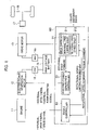
- Fig 1 is a block diagram showing schematic configuration of a series-type hybrid vehicle that serves as an example of a hybrid vehicle.
- a powertrain of the series-type hybrid vehicle includes an engine 11 (an internal combustion engine), an electrical power generation motor 12 (an electrical power generating motor), a drive motor 13 (a driving motor), a high voltage battery 14, an inverter 15 for the electrical power generation motor, an inverter 16 for the drive motor, and a speed reduction mechanism 17.
- the series-type hybrid vehicle shown in the present embodiment has a single pedal, and is a so-called one-pedal type vehicle in which a so-called one-pedal control, in which acceleration is made by pushing this pedal and deceleration is made by releasing the pedal, is carried out.
- a so-called one-pedal control in which acceleration is made by pushing this pedal and deceleration is made by releasing the pedal, is carried out.
- the one-pedal type vehicle it is possible to run the vehicle only by on and off of the pedal.
- the present invention is not limited to a one-pedal type vehicle.
- the series-type hybrid vehicle runs the vehicle by operating the engine 11 in a firing operation or a motoring operation.
- the firing operation is an operation for charging the high voltage battery 14 by supplying fuel to the engine 11 and combusting it to rotate the electrical power generation motor 12.
- the motoring operation is an operation for reducing an SOC (state of charge) of the high voltage battery 14 by rotating the engine 11 by use of the electrical power generation motor 12 with no combustion in the engine 11.
- the engine 11 is started by a drive force of the electrical power generation motor 12 connected with an output shaft of the engine 11 when an electrical power generation request signal is input, and then driven to rotate while fuel is supplied thereto.
- the electrical power generation request signal transitions to an electrical power generation stop signal, its rotation is stopped.
- the electrical power generation motor 12 whose rotor is jointed with the engine 11, generates alternating-current electrical power while the rotor rotates due to rotations of the engine 11.
- the drive motor 13 which is jointed with drive wheels 18 of the vehicle via the speed reduction mechanism 17, drives the vehicle during start acceleration, constant speed running and intermediate acceleration, and generates regenerative electrical power during deceleration.
- the high voltage battery 14 stores the electrical power generated by the electrical power generation motor 12 and the regenerative electrical power generated by the drive motor 13. In addition, it supplies electrical power to the drive motor 13. At the start-up of the engine 11, it supplies electrical power required for the start-up to the electrical power generation motor 12.
- the inverter 15 for the electrical power generation motor is disposed between the electrical power generation motor 12 and the high voltage battery 14, and converts the alternating current electrical power generated by the electrical power generation motor 12 to direct current electrical power to charge the high voltage battery 14.
- the inverter 16 for the drive motor is disposed between the drive motor 13 and the high voltage battery 14, and converts the direct current electrical power output from the high voltage battery 14 to three-phase alternating current electrical power to supply it to the drive motor 13.
- a control system of the series-type hybrid vehicle shown in Fig. 1 includes a control apparatus 100 that controls a rotational speed of the engine 11 and a rotational speed of the drive motor 13.
- the control apparatus 100 includes a vehicle controller 21, an engine controller 22 and an electrical power generation controller 23. Note that the control apparatus 100 shown in Fig, 1 shows only its featured configurations according to the present invention, and functions other than them are omitted.
- the vehicle controller 21, the engine controller 22 and the electrical power generation controller 23 that configure the control apparatus 100 are feasible by using a micro-computer provided with a CPU (central processing unit), a memory and an input/output unit.
- a computer program for functioning the micro-computer as the vehicle controller 21, the engine controller 22 and the electrical power generation controller 23 is installed in the micro-computer and then executed.
- the micro-computer functions as plural information processing circuits included in the vehicle controller 21, the engine controller 22 and the electrical power generation controller 23.
- an example, in which the vehicle controller 21, the engine controller 22 and the electrical power generation controller 23 are achieved by software, is shown here, but, of course, they may be configured by preparing a specific hardware(s) for executing each information processing.
- plural circuits included in the vehicle controller 21, the engine controller 22 and the electrical power generation controller 23 may be configured by individual hardware.
- the vehicle controller 21 includes a rotational speed control circuit 211 and a rotational speed setting circuit 212.
- the rotational speed control circuit 211 outputs a rotational speed command signal and a torque command signal to the engine controller 22 so that the rotational speed and the output torque of the engine 11 (internal combustion engine) becomes a preset target rotational speed and a preset target output torque. Further, it outputs a rotational speed command signal so that the rotational speed of the electrical power generation motor 12 becomes a preset target rotational speed.
- the rotational speed setting circuit 212 retrieves a failure judgement signal of a device relating to the engine 11.
- the failure judgement signal is output from an ECU (Electronic Control Unit: not shown in the drawings) installed in the vehicle at a failure occurrence, where a coolant temperature sensor that measures a temperature of coolant fails or where overheating occurs for example, it retrieves this failure judgement signal.
- the failure judgement signal sets a rotational speed for stopping fuel supply to the engine 11, i.e. an F/C rotational speed that is a rotational speed for carrying out fuel cut.
- a rotational speed for restarting fuel supply after the fuel cut i.e. an F/C recovery rotational speed that is a rotational speed for stopping the fuel cut.
- the F/C rotational speed is 2000 to 2500 rpm (hereinafter, it is denoted as "R1 rpm”) for example, and the F/C recovery rotational speed is 1800 to 2300 rpm (hereinafter, it is denoted as "R2 rpm”) for example.
- the rotational speed setting circuit 212 sets an upper limit of a target rotational speed of the firing operation of the engine 11 (an on-failure upper limit rotational speed) when the failure judgement signal is input.
- this is called as a "first upper limit rotational speed”.
- it sets a target rotational speed of the motoring operation to a second upper limit rotational speed that is not higher than the first upper limit rotational speed.
- the first upper limit rotational speed is set to a rotational speed slightly lower than the above-mentioned F/C recovery rotational speed.
- R3 rpm the rotational speed slightly lower than the above-mentioned F/C recovery rotational speed.
- R2 > R3.
- the first upper limit rotational speed is set to a rotational speed lower than an upper limit when the failure judgement signal is not input (a normal state).
- the second upper limit rotational speed is set to be not higher than the first upper limit rotational speed.
- R3 rpm an example in which the first upper limit rotational speed and the second upper limit rotational speed are set identically to R3 rpm will be explained as one example. Then, it outputs the set target rotational speeds to the engine controller 22 and the electrical power generation controller 23.
- the engine controller 22 controls the rotational speed of the engine 11 when the engine 11 is operated under the firing operation so as to make it become the target rotational speed of the firing operation output from the vehicle controller 21.
- the coolant temperature sensor that is a device relating to the engine 11 fails or where overheating occurs (when the failure judgement signal is input)
- the electrical power generation controller 23 controls driving of the electrical power generation motor 12 based on the rotational speed set by the rotational speed command output from the vehicle controller 21. In addition, when the failure judgement signal is input, it controls the rotational speed of the electrical power generation motor 12 so as to make it become not higher than R3 rpm that is the second upper limit rotational speed set by the vehicle controller 21.
- Fig. 3 is a timing chart of operations when a failure occurs during the firing operation
- Fig. 4 is a timing chart of operations when a failure occurs during the motoring operation.
- the engine 11 is initially driven at a high rotational speed (e.g. 4000 to 5000 rpm) by the firing operation or the motoring operation.
- a step S11 the vehicle controller 21 judges whether or not the failure judgement signal is input.
- the failure judgement signal is input when the coolant temperature sensor fails or overheating occurs.
- the vehicle controller 21 judges whether or not a state of the engine 11 is the firing operation or the motoring operation in a step S12.
- the process flow proceeds to a step S13.
- steps S13 to S18 operations of the firing operation shown by steps S13 to S18 will be explained with reference to the timing chart shown in Fig. 3 .
- the vehicle controller 21 carries out fuel cut of the engine 11 (stop supplying fuel). The fuel cut is done for all cylinders as shown in Fig. 3(c) , and thereby the engine 11 is shifted to the motoring operation.
- a step S14 the vehicle controller 21 decreases the rotational speed of the engine 11 under the motoring operation at an almost constant decrease rate (gradient). Namely, in a case where the failure judgement signal is input while the engine 11 rotates at a higher rotational speed than the first upper limit rotational speed (R3 rpm) and a state before the failure judgement is the firing operation, it is shifted to the motoring operation. Further, the engine rotational speed under the motoring operation is decreased.
- the engine rotational speed gradually decreases from the time t1 as shown by a sign Q1 in Fig. 3(b) , and then reaches the F/C recovery rotational speed (e.g. R2 rpm) at a time t2.
- the F/C recovery rotational speed e.g. R2 rpm
- a step S15 it is judged whether or not the rotational speed of the engine 11 decreases to R2 rpm that is the F/C recovery rotational speed. Since the engine rotational speed decreases to R2 rpm at the time t2 shown in Fig. 3 , the vehicle controller 21 shifts the engine 11 from the motoring operation to the firing operation in a step S16.
- the vehicle controller 21 decreases the rotational speed of the engine 11 again in a step S17, and judges whether or not it decreases to the first upper limit rotational speed (R3 rom) that is an upper limit rotational speed during a failure in the firing operation in a step S18. When it decreases thereto, this rotational speed is kept in a step S21.
- the engine rotational speed By setting the first upper limit rotational speed to R3 rpm slightly lower than R2 rpm that is the F/C recovery rotational speed, the engine rotational speed surely becomes lower than the F/C recovery rotational speed, even if the engine rotational speed slightly fluctuates. Therefore, the fuel cut is stopped and then the number of the F/C cylinders becomes zero. According to this, transition between the firing operation and the motoring operation can be done quickly.
- the vehicle controller 21 decreases the rotational speed of the engine 11. Namely, in a case where a failure is judged while the engine 11 rotates at a higher rotational speed than the first upper limit rotational speed and a state before the failure judgement is the motoring operation, the motoring operation is maintained and the rotational speed is limited to the second upper limit rotational speed set not higher than the first upper limit rotational speed by monotonically decreasing it.
- the failure judgement signal is input at a time t11 and then the engine rotational speed under the motoring operation decreases at an almost constant decrease rate (gradient). Therefore, the engine rotational speed gradually decreases as shown by a sign Q2 in Fig. 4(b) .
- the decrease ratio at this time is equivalent to the decrease rate shown in Fig. 3(b) . Namely, the decrease rate for monotonically decreasing the rotational speed is made equivalent when a state before the failure judgement is the motoring operation and when that is the firing operation.
- a step S20 it is judged whether or not to decrease to the second upper limit rotational speed (R3 rpm) that is an upper limit rotational speed during a failure in the motoring operation.
- R3 rpm the second upper limit rotational speed
- the fig. 6 is a timing chart showing operations when a failure occurs a low rotational speed under the motoring operation.
- the engine 11 is initially operated under the motoring operation at a lower rotational speed than R3 rpm as shown in Fig. 6(b) . Because of the motoring operation, the number of the F/C cylinders is set to its maximum as shown in Fig. 6(c) . Namely, fuel is not supplied to the engine 11. In a step S31, the vehicle controller 21 judges whether or not the failure judgement signal is input.
- the vehicle controller 21 judges whether or not increase request of the engine rotational speed is generated in a step S32.
- a step S32 For example, Electrical power generated due to rotations of the electrical power generation motor 12 cannot be charged to the high voltage battery 14 in a case where an accelerator opening of the vehicle increases while the SOC of the high voltage battery 14 takes an almost upper limit value. Therefore, the generated electrical power is consumed by rotating of the engine 11. According to this, it is required to increase the rotational speed of the engine 11, and thereby the YES judgement is made in the step S32 (see a time t21 in Fig. 6 ).
- the vehicle controller 21 outputs an increase command of the engine rotational speed to the engine controller 22.
- the engine controller 22 increases the rotational speed of the engine 11 at a constant increase rate (gradient) as shown by a sign Q3 in Fig. 6(b) .
- a step S34 the vehicle controller 21 judges whether or not the rotational speed of the engine 11 reaches R3 rpm that is the second upper limit rotational speed. When it reaches R3 rpm, a control for keeping this rotational speed is done in a step S35.
- the first upper limit rotational speed is set to R3 rpm that is lower than R2 rpm that is the F/C recovery rotational speed is explained in the above embodiment, but it can be set not higher than R1 rpm that is the F/C rotational speed.
Landscapes
- Engineering & Computer Science (AREA)
- Chemical & Material Sciences (AREA)
- Combustion & Propulsion (AREA)
- Mechanical Engineering (AREA)
- Transportation (AREA)
- General Engineering & Computer Science (AREA)
- Automation & Control Theory (AREA)
- Health & Medical Sciences (AREA)
- Biomedical Technology (AREA)
- General Health & Medical Sciences (AREA)
- Hybrid Electric Vehicles (AREA)
- Electric Propulsion And Braking For Vehicles (AREA)
- Control Of Vehicle Engines Or Engines For Specific Uses (AREA)
Description
- The present invention relates to a control apparatus of a hybrid vehicle and a control method of a hybrid vehicle.
- For example, a
Patent Literature 1 discloses that, when a device relating to an engine (internal combustion engine), such as a coolant temperature sensor, of a hybrid vehicle fails, a drastic change of a rotational speed of the engine in a high vehicle speed state is restricted by shifting it into a motoring operation to prevent an occurrence of a secondary failure. - Patent Literature 1: Japanese Patent Application Publication
JP 2010 111 321 A - Prior art document
US 5 788 597 A proposes a process and apparatus for braking a hybrid drive vehicle, kinetic vehicular energy is converted by the driving electric motor into electrical power, which alternatively can be absorbed by charging a traction battery or by driving a combustion engine via a generator coupled to the engine, which is functioning as a motor. According to the invention, engine braking is activated if the traction battery is fully charged, if its temperature lies outside a predetermined charging temperature range, or if the charging current due to the electrical power supplied by the driving electric motor exceeds a predetermined limit value. - Prior art document
EP 3 150 829 A1 suggests an engine control apparatus includes a temperature sensor configured to detect engine-related temperature information, a first calculator configured to calculate a first limit output value of an engine based on the temperature information inputted from the temperature sensor, an oil pressure sensor configured to detect a pressure of engine oil, a second calculator configured to calculate a second limit output value of the engine based on the oil pressure inputted from the oil pressure sensor, and a determiner configured to determine one of the first and second limit output values inputted from the first and second calculators as an optimal limit output value of the engine. - However, since an upper limit rotational speed is not set when shifting into the motoring operation from a firing operation in the prior-art example disclosed in the
Patent Literature 1, there is a problem that transition between the firing operation and the motoring operation is not done quickly and thereby acceleration responsiveness degrades. - The present invention is made in order to solve such a prior-art problem, and its object is to provide a control method of a hybrid vehicle and a control apparatus of a hybrid vehicle that can carry out transition between a firing operation and a motoring operation quickly.
- The object underlying the present invention is achieved by a control method of a hybrid vehicle according to
independent claim 1 and by a control apparatus of a hybrid vehicle according to independent claim 7. Preferred embodiments are defined in the respective dependent claims. - According to the present invention, a control method of a hybrid vehicle is proposed, wherein the vehicle includes an internal combustion engine and an electrical power generating motor, that is connected with the internal combustion engine for controlling a rotational speed of the internal combustion engine to be a target rotational speed.
- The method comprises - when a failure with respect to the internal combustion engine is judged -
- (i) setting an upper limit of the target rotational speed of a firing operation of the internal combustion engine to an on-failure upper limit rotational speed that is lower than an on-failure fuel cut rotational speed that is a rotational speed for stopping fuel supply to the internal combustion engine during the failure; and
- (ii) setting the target rotational speed of a motoring operation of the internal combustion engine to be not higher than an on-failure fuel cut recovery rotational speed that is a rotational speed for restarting the fuel supply after the fuel cut during the failure.
- Thus an aspect of the present invention is to set an upper limit of a target rotational speed for a firing operation to an on-failure upper limit rotational speed when a failure is judged with respect to an internal combustion engine. In addition, a target rotational speed for a motoring operation is set to be not higher than the on-failure upper limit rotational speed.
- According to the aspect of the present invention, it becomes possible to carry out transition between the firing operation and the motoring operation quickly even when a failure is judged with respect to the internal combustion engine.
-
- [
Fig. 1] Fig. 1 is a block diagram showing configuration of a control apparatus of a hybrid vehicle according to an embodiment of the present invention. - [
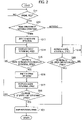
Fig. 2] Fig. 2 is a flowchart showing operation processes of the control apparatus of a hybrid vehicle according to the embodiment of the present invention. - [
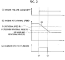
Fig. 3] Fig. 3 is a timing chart showing changes of a rotational speed of an engine and the number of F/C cylinders in a case where a failure occurs while the engine is operated in a firing operation. - [
Fig. 4] Fig. 4 is a timing chart showing changes of a rotational speed of an engine and the number of F/C cylinders in a case where a failure occurs while the engine is operated in a motoring operation. - [
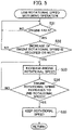
Fig. 5] Fig. 5 is a flowchart showing operation processes in a case where a failure occurs while a rotational speed of the engine is low. - [
Fig. 6] Fig. 6 is a timing chart showing changes of a rotational speed of an engine and the number of F/C cylinders in a case where a failure occurs while a rotational speed of the engine is low. - Hereinafter, an embodiment of the present invention will be explained with reference to the drawings.
-
Fig 1 is a block diagram showing schematic configuration of a series-type hybrid vehicle that serves as an example of a hybrid vehicle. As shown inFig. 1 , a powertrain of the series-type hybrid vehicle includes an engine 11 (an internal combustion engine), an electrical power generation motor 12 (an electrical power generating motor), a drive motor 13 (a driving motor), ahigh voltage battery 14, aninverter 15 for the electrical power generation motor, an inverter 16 for the drive motor, and aspeed reduction mechanism 17. - In addition, although not shown in the drawings, the series-type hybrid vehicle shown in the present embodiment has a single pedal, and is a so-called one-pedal type vehicle in which a so-called one-pedal control, in which acceleration is made by pushing this pedal and deceleration is made by releasing the pedal, is carried out. In the one-pedal type vehicle, it is possible to run the vehicle only by on and off of the pedal. Of course, the present invention is not limited to a one-pedal type vehicle.
- The series-type hybrid vehicle runs the vehicle by operating the
engine 11 in a firing operation or a motoring operation. The firing operation is an operation for charging thehigh voltage battery 14 by supplying fuel to theengine 11 and combusting it to rotate the electricalpower generation motor 12. The motoring operation is an operation for reducing an SOC (state of charge) of thehigh voltage battery 14 by rotating theengine 11 by use of the electricalpower generation motor 12 with no combustion in theengine 11. - The
engine 11 is started by a drive force of the electricalpower generation motor 12 connected with an output shaft of theengine 11 when an electrical power generation request signal is input, and then driven to rotate while fuel is supplied thereto. When the electrical power generation request signal transitions to an electrical power generation stop signal, its rotation is stopped. - The electrical
power generation motor 12, whose rotor is jointed with theengine 11, generates alternating-current electrical power while the rotor rotates due to rotations of theengine 11. - The
drive motor 13, which is jointed withdrive wheels 18 of the vehicle via thespeed reduction mechanism 17, drives the vehicle during start acceleration, constant speed running and intermediate acceleration, and generates regenerative electrical power during deceleration. - The
high voltage battery 14 stores the electrical power generated by the electricalpower generation motor 12 and the regenerative electrical power generated by thedrive motor 13. In addition, it supplies electrical power to thedrive motor 13. At the start-up of theengine 11, it supplies electrical power required for the start-up to the electricalpower generation motor 12. - The
inverter 15 for the electrical power generation motor is disposed between the electricalpower generation motor 12 and thehigh voltage battery 14, and converts the alternating current electrical power generated by the electricalpower generation motor 12 to direct current electrical power to charge thehigh voltage battery 14. - The inverter 16 for the drive motor is disposed between the
drive motor 13 and thehigh voltage battery 14, and converts the direct current electrical power output from thehigh voltage battery 14 to three-phase alternating current electrical power to supply it to thedrive motor 13. - In addition, a control system of the series-type hybrid vehicle shown in
Fig. 1 includes acontrol apparatus 100 that controls a rotational speed of theengine 11 and a rotational speed of thedrive motor 13. Thecontrol apparatus 100 includes avehicle controller 21, anengine controller 22 and an electricalpower generation controller 23. Note that thecontrol apparatus 100 shown inFig, 1 shows only its featured configurations according to the present invention, and functions other than them are omitted. - Note that the
vehicle controller 21, theengine controller 22 and the electricalpower generation controller 23 that configure thecontrol apparatus 100 are feasible by using a micro-computer provided with a CPU (central processing unit), a memory and an input/output unit. A computer program for functioning the micro-computer as thevehicle controller 21, theengine controller 22 and the electricalpower generation controller 23 is installed in the micro-computer and then executed. According to this, the micro-computer functions as plural information processing circuits included in thevehicle controller 21, theengine controller 22 and the electricalpower generation controller 23. Note that an example, in which thevehicle controller 21, theengine controller 22 and the electricalpower generation controller 23 are achieved by software, is shown here, but, of course, they may be configured by preparing a specific hardware(s) for executing each information processing. In addition, plural circuits included in thevehicle controller 21, theengine controller 22 and the electricalpower generation controller 23 may be configured by individual hardware. - The
vehicle controller 21 includes a rotationalspeed control circuit 211 and a rotationalspeed setting circuit 212. The rotationalspeed control circuit 211 outputs a rotational speed command signal and a torque command signal to theengine controller 22 so that the rotational speed and the output torque of the engine 11 (internal combustion engine) becomes a preset target rotational speed and a preset target output torque. Further, it outputs a rotational speed command signal so that the rotational speed of the electricalpower generation motor 12 becomes a preset target rotational speed. - The rotational
speed setting circuit 212 retrieves a failure judgement signal of a device relating to theengine 11. For example, when the failure judgement signal is output from an ECU (Electronic Control Unit: not shown in the drawings) installed in the vehicle at a failure occurrence, where a coolant temperature sensor that measures a temperature of coolant fails or where overheating occurs for example, it retrieves this failure judgement signal. When the failure judgement signal occurs, it sets a rotational speed for stopping fuel supply to theengine 11, i.e. an F/C rotational speed that is a rotational speed for carrying out fuel cut. Further, it sets a rotational speed for restarting fuel supply after the fuel cut, i.e. an F/C recovery rotational speed that is a rotational speed for stopping the fuel cut. The F/C rotational speed is 2000 to 2500 rpm (hereinafter, it is denoted as "R1 rpm") for example, and the F/C recovery rotational speed is 1800 to 2300 rpm (hereinafter, it is denoted as "R2 rpm") for example. Here, R1 > R2. Therefore, the fuel cut is done when the failure judgement signal is input and the engine rotational speed once increases up to R1 rpm, and then the fuel cut is continued until the engine rotational speed decreases to R2 rpm. - Furthermore, the rotational
speed setting circuit 212 sets an upper limit of a target rotational speed of the firing operation of the engine 11 (an on-failure upper limit rotational speed) when the failure judgement signal is input. Hereinafter, this is called as a "first upper limit rotational speed". Furthermore, it sets a target rotational speed of the motoring operation to a second upper limit rotational speed that is not higher than the first upper limit rotational speed. For example, the first upper limit rotational speed is set to a rotational speed slightly lower than the above-mentioned F/C recovery rotational speed. For example, it is set to 1750 to 2250 rpm (hereinafter, it is denoted as "R3 rpm"). Here, R2 > R3. Namely, the first upper limit rotational speed is set to a rotational speed lower than an upper limit when the failure judgement signal is not input (a normal state). In addition, the second upper limit rotational speed is set to be not higher than the first upper limit rotational speed. In the present embodiment, an example in which the first upper limit rotational speed and the second upper limit rotational speed are set identically to R3 rpm will be explained as one example. Then, it outputs the set target rotational speeds to theengine controller 22 and the electricalpower generation controller 23. - The
engine controller 22 controls the rotational speed of theengine 11 when theengine 11 is operated under the firing operation so as to make it become the target rotational speed of the firing operation output from thevehicle controller 21. In addition, at the failure occurrence where the coolant temperature sensor that is a device relating to theengine 11 fails or where overheating occurs (when the failure judgement signal is input), it outputs the rotational speed command signal to theengine 11 such that the rotational speed of theengine 11 becomes not higher than R3 rpm that is the above-mentioned first upper limit rotational speed. Namely, at the failure occurrence, an occurrence of a secondary failure is prevented by decreasing the rotational speed of theengine 11. - While the
engine 11 is operated under the motoring operation, the electricalpower generation controller 23 controls driving of the electricalpower generation motor 12 based on the rotational speed set by the rotational speed command output from thevehicle controller 21. In addition, when the failure judgement signal is input, it controls the rotational speed of the electricalpower generation motor 12 so as to make it become not higher than R3 rpm that is the second upper limit rotational speed set by thevehicle controller 21. - Next, operation processes of the
control apparatus 100 of the hybrid vehicle according to the present embodiment that is configured as described above will be explained with reference to a flowchart shown inFig. 2 , andFig. 3 andFig. 4 .Fig. 3 is a timing chart of operations when a failure occurs during the firing operation, andFig. 4 is a timing chart of operations when a failure occurs during the motoring operation. - The
engine 11 is initially driven at a high rotational speed (e.g. 4000 to 5000 rpm) by the firing operation or the motoring operation. In a step S11, thevehicle controller 21 judges whether or not the failure judgement signal is input. For example, the failure judgement signal is input when the coolant temperature sensor fails or overheating occurs. - When the failure judgement signal is input, the
vehicle controller 21 judges whether or not a state of theengine 11 is the firing operation or the motoring operation in a step S12. - In a case of the firing operation, the process flow proceeds to a step S13. Hereinafter, operations of the firing operation shown by steps S13 to S18 will be explained with reference to the timing chart shown in
Fig. 3 . When the failure judgement signal is input at a time t1 as shown inFig. 3(a) , thevehicle controller 21 carries out fuel cut of the engine 11 (stop supplying fuel). The fuel cut is done for all cylinders as shown inFig. 3(c) , and thereby theengine 11 is shifted to the motoring operation. - In a step S14, the
vehicle controller 21 decreases the rotational speed of theengine 11 under the motoring operation at an almost constant decrease rate (gradient). Namely, in a case where the failure judgement signal is input while theengine 11 rotates at a higher rotational speed than the first upper limit rotational speed (R3 rpm) and a state before the failure judgement is the firing operation, it is shifted to the motoring operation. Further, the engine rotational speed under the motoring operation is decreased. - The engine rotational speed gradually decreases from the time t1 as shown by a sign Q1 in
Fig. 3(b) , and then reaches the F/C recovery rotational speed (e.g. R2 rpm) at a time t2. By making the decrease rate of the rotational speed almost constant (monotonically decreasing), noise occurrence and noise fluctuation can be prevented and it can be avoided to provide a feeling of strangeness to a passenger of the vehicle. - In a step S15, it is judged whether or not the rotational speed of the
engine 11 decreases to R2 rpm that is the F/C recovery rotational speed. Since the engine rotational speed decreases to R2 rpm at the time t2 shown inFig. 3 , thevehicle controller 21 shifts theengine 11 from the motoring operation to the firing operation in a step S16. - The
vehicle controller 21 decreases the rotational speed of theengine 11 again in a step S17, and judges whether or not it decreases to the first upper limit rotational speed (R3 rom) that is an upper limit rotational speed during a failure in the firing operation in a step S18. When it decreases thereto, this rotational speed is kept in a step S21. - By setting the first upper limit rotational speed to R3 rpm slightly lower than R2 rpm that is the F/C recovery rotational speed, the engine rotational speed surely becomes lower than the F/C recovery rotational speed, even if the engine rotational speed slightly fluctuates. Therefore, the fuel cut is stopped and then the number of the F/C cylinders becomes zero. According to this, transition between the firing operation and the motoring operation can be done quickly.
- On the other hand, in a case where the
engine 11 is in the motoring operation when the failure judgement signal is input ("motoring" in the step S12), the process flow proceeds to a step S19. Hereinafter, the motoring operation shown in the steps S19 and S20 will be explained with reference to the timing chart shown inFig. 4 . - In the step S19, the
vehicle controller 21 decreases the rotational speed of theengine 11. Namely, in a case where a failure is judged while theengine 11 rotates at a higher rotational speed than the first upper limit rotational speed and a state before the failure judgement is the motoring operation, the motoring operation is maintained and the rotational speed is limited to the second upper limit rotational speed set not higher than the first upper limit rotational speed by monotonically decreasing it. - By explaining this with reference to
Fig.4 , the failure judgement signal is input at a time t11 and then the engine rotational speed under the motoring operation decreases at an almost constant decrease rate (gradient). Therefore, the engine rotational speed gradually decreases as shown by a sign Q2 inFig. 4(b) . The decrease ratio at this time is equivalent to the decrease rate shown inFig. 3(b) . Namely, the decrease rate for monotonically decreasing the rotational speed is made equivalent when a state before the failure judgement is the motoring operation and when that is the firing operation. - In a step S20, it is judged whether or not to decrease to the second upper limit rotational speed (R3 rpm) that is an upper limit rotational speed during a failure in the motoring operation. When it is judged that the rotational speed Q2 decreases to R3 rpm as shown by a time t12 in
Fig. 4 , a control for keeping this rotational speed is done in the step S21. - In this manner, the rotational speed control upon an input of the failure judgement signal while the
engine 11 is driven at a high rotational speed is done. - Next, operation processes upon a failure occurrence while the
engine 11 rotates at a low rotational speed under the motoring operation will be explained with reference to a flowchart shown inFig. 5 , andFig. 6 . Thefig. 6 is a timing chart showing operations when a failure occurs a low rotational speed under the motoring operation. - The
engine 11 is initially operated under the motoring operation at a lower rotational speed than R3 rpm as shown inFig. 6(b) . Because of the motoring operation, the number of the F/C cylinders is set to its maximum as shown inFig. 6(c) . Namely, fuel is not supplied to theengine 11. In a step S31, thevehicle controller 21 judges whether or not the failure judgement signal is input. - When the failure judgement signal is input as shown in
Fig. 6(a) , thevehicle controller 21 judges whether or not increase request of the engine rotational speed is generated in a step S32. For example, Electrical power generated due to rotations of the electricalpower generation motor 12 cannot be charged to thehigh voltage battery 14 in a case where an accelerator opening of the vehicle increases while the SOC of thehigh voltage battery 14 takes an almost upper limit value. Therefore, the generated electrical power is consumed by rotating of theengine 11. According to this, it is required to increase the rotational speed of theengine 11, and thereby the YES judgement is made in the step S32 (see a time t21 inFig. 6 ). In a step S33, thevehicle controller 21 outputs an increase command of the engine rotational speed to theengine controller 22. Theengine controller 22 increases the rotational speed of theengine 11 at a constant increase rate (gradient) as shown by a sign Q3 inFig. 6(b) . - In a step S34, the
vehicle controller 21 judges whether or not the rotational speed of theengine 11 reaches R3 rpm that is the second upper limit rotational speed. When it reaches R3 rpm, a control for keeping this rotational speed is done in a step S35. - In this manner, in a case where the request for increasing the rotational speed of the
engine 11 is generated while theengine 11 is operated at a low rotational speed under the motoring operation, it increases up to R3 rpm that is the second upper limit rotational speed at a constant increase rate and then this rotational speed is kept. Therefore, the rotational speed of theengine 11 in the motoring operation can be prevented from increasing largely, and thereby quick transition can be achieved when shifting to the firing operation. - Note that the example in which the first upper limit rotational speed is set to R3 rpm that is lower than R2 rpm that is the F/C recovery rotational speed is explained in the above embodiment, but it can be set not higher than R1 rpm that is the F/C rotational speed.
- As explained above, following advantages can be brought in the control apparatus of a hybrid vehicle according to the present embodiment.
- (1) It is difficult to transition quickly between the two operation states in a case where no upper limit rotational speed at a failure occurrence is set or a case where an upper limit rotational speed for the firing operation is largely different from that for the motoring operation. Therefore, accelerating and decelerating responsiveness degrade and thereby a passenger feels strangeness. In the present embodiment, in a case where the failure judgement signal is input while the
engine 11 is operated under both the firing operation and the motoring operation, the engine rotational speed is limited quickly to the first upper limit rotational speed that is an upper limit rotational speed in the firing operation or the second upper limit rotational speed that is an upper limit rotational speed in the motoring operation. Therefore, transition from the firing operation to the motoring operation or transition from the motoring operation to the firing operation can be carried out quickly, and thereby responsiveness can be improved. - (2) In a case where the failure judgement signal is input while the
engine 11 rotates at a higher rotational speed (e.g. 4000 to 5000 rpm) than an on-failure upper limit rotational speed (the first upper limit rotational speed) under the firing operation, it is shifted to the motoring operation and then its rotational speed is decreased to the first upper limit rotational speed (R3 rpm) slightly lower than the F/C recovery rotational speed.
In order to decrease the rotational speed quickly while maintaining the firing operation, electrical power generation is needed. However, the electricalpower generation motor 12 cannot generate electrical power when the SOC of thehigh voltage battery 14 is high. In the present embodiment, even when the SOC of thehigh voltage battery 14 is high, it is possible to decrease the engine rotational speed quickly by transitioning to the motoring operation. - (3) In addition, since the rotational speed of the motoring operation is controlled, the decrease rate (gradient) for decreasing the rotational speed can be set to a decrease rate that never provides a feeling of strangeness such as a noise occurrence. Namely, fuel cut is merely done when the failure judgement signal is input and the decrease rate of the rotational speed is not controlled in a prior-art and thereby a problem such as a noise occurrence may occur due to changes of the decrease rate, but such a problem can be prevented in the present embodiment.
- (4) In a case where the failure judgement signal is input when the
engine 11 is operated under the motoring operation and rotates at the higher rotational speed (e.g. 4000 to 5000 rpm) than the on-failure upper limit rotational speed (the first upper limit rotational speed), the motoring operation is maintained and it is decreased to the second upper limit rotational speed (R3 rpm) slightly lower than the F/C recovery rotational speed.
The fact that a state before the failure judgement signal is input is the motoring operation means that it is a state where the electrical power stored in thehigh voltage battery 14 is consumed by the electricalpower generation motor 12. In such a case, by decreasing the rotational speed at the constant gradient by the rotational speed control, changes of deceleration and changes of noises can be reduced with no rapid change of electrical power consumed by the electricalpower generation motor 12. As the result, feelings of strangeness and fearfulness that a passenger feels can be prevented. In addition, after the engine rotational speed has decreased, it becomes possible to carry out the transition between the firing operation and the motoring operation quickly. - (5) By making the decrease rate (gradient) for monotonically decreasing the rotational speed equivalent between a case where a state before the failure judgement signal is input (before a failure is judged) is the motoring and a case where it is the firing operation, decelerations and noises that occur in the vehicle can be made coincident with each other and thereby feelings of strangeness and fearfulness that a passenger feels can be prevented.
- (6) By setting the on-failure upper limit rotational speed for the firing operation (the first upper limit rotational speed) to the F/C rotational speed and setting the target rotational speed for the motoring operation (the second upper limit rotational speed) to be not higher than the F/C recovery rotational speed, it becomes possible to transition to the firing operation quickly after the rotational speed has decreased and thereby the responsiveness can be improved.
- (7) The hybrid vehicle is a vehicle with the one-pedal control in which acceleration is made by the
drive motor 13 when a single pedal is pushed and deceleration is made when the pedal is released. Namely, since the drive source of the vehicle is the drive motor 13 (driving motor) that is driven by electrical power supplied from thehigh voltage battery 14, and has a function for generating a negative driving force (deceleration) in the vehicle, it is possible to decrease the engine rotational speed to R3 rpm by releasing the pedal when the failure judgement signal is input. -
- 11
- engine (internal combustion engine)
- 12
- electrical power generation motor (electrical power generating motor)
- 13
- drive motor (driving motor)
- 14
- high voltage battery
- 15
- inverter for the electrical power generation motor
- 16
- inverter for the drive motor
- 17
- speed reduction mechanism
- 18
- drive wheel
- 21
- vehicle controller
- 22
- engine controller
- 23
- electrical power generation controller
- 100
- control apparatus
Claims (7)
- A control method of a hybrid vehicle,the vehicle including an internal combustion engine (11) and an electrical power generating motor (12), that is connected with the internal combustion engine (11) for controlling a rotational speed of the internal combustion engine (11) to be a target rotational speed,the method comprising, when a failure with respect to the internal combustion engine (11) is judged,- setting an upper limit of the target rotational speed of a firing operation of the internal combustion engine (11) to an on-failure upper limit rotational speed (R3) that is lower than an on-failure fuel cut rotational speed (R1) that is a rotational speed for stopping fuel supply to the internal combustion engine (11) during the failure; and- setting the target rotational speed of a motoring operation of the internal combustion engine (11) to be not higher than an on-failure fuel cut recovery rotational speed (R2) that is a rotational speed for restarting the fuel supply after the fuel cut during the failure.
- The control method according to claim 1, further comprising:- when a failure is judged while the internal combustion engine (11) rotates at a higher rotational speed than the on-failure rotational speed (R3) and a state before the failure judgement is the firing operation,- transitioning to the motoring operation; and- decreasing the rotational speed (Q1) during the motoring operation.
- The control method according to claim 2, further comprising limiting the rotational speed (Q1) to be not higher than the on-failure upper limit rotational speed (R3) by monotonically decreasing the rotational speed (Q1).
- The control method according to any one of the preceding claims,
further comprising, when a failure is judged while the internal combustion engine rotates at a higher rotational speed than the on-failure rotational speed (R3) and a state before the failure judgement is the motoring operation,- maintaining the motoring operation; and- limiting the rotational speed (Q2) to be not higher than the on-failure upper limit rotational speed (R3) by monotonically decreasing the rotational speed (Q2). - The control method according to any one of claim 3 or 4, wherein a decrease rate for monotonically decreasing the rotational speed (Q1, Q2) is made equivalent when the state before the failure judgement is the motoring operation and when that is the firing operation.
- The control method of a hybrid vehicle according to any one of the preceding claims, wherein:- a drive source of the hybrid vehicle is a driving motor (13) for driving by electrical power supplied from a high voltage battery (14),- the hybrid vehicle has a function for making acceleration by pushing a pedal and making deceleration by releasing the pedal, and- the target rotational speed of the motoring operation is set not higher than the on-failure upper limit rotational speed (R3) when the failure with respect to the internal combustion engine (11) is judged.
- A control apparatus (100) of a hybrid vehicle,the vehicle comprising:- an internal combustion engine (11); and- an electrical power generating motor (12) that is connected with the internal combustion engine (11); andthe control apparatus (100) comprising:- a rotational speed control circuit (211) that is configured to control a rotational speed of the internal combustion engine (11) to be a target rotational speed; and- a rotational speed setting circuit (212) that is configured, when an failure with respect to the internal combustion engine (11) is judged,- to set an upper limit of the target rotational speed of a firing operation of the internal combustion engine (11) to an on-failure upper limit rotational speed (R3) that is lower than an on-failure fuel cut rotational speed (R1) that is a rotational speed for stopping fuel supply to the internal combustion engine (11) during the failure, and- to set the target rotational speed of a motoring operation of the internal combustion engine (11) to be not higher than an on-failure fuel cut recovery rotational speed (R2) that is a rotational speed for restarting the fuel supply after the fuel cut during the failure.
Applications Claiming Priority (1)
| Application Number | Priority Date | Filing Date | Title |
|---|---|---|---|
| PCT/JP2017/045170 WO2019116556A1 (en) | 2017-12-15 | 2017-12-15 | Method and device for controlling hybrid vehicle |
Publications (3)
| Publication Number | Publication Date |
|---|---|
| EP3725625A1 EP3725625A1 (en) | 2020-10-21 |
| EP3725625A4 EP3725625A4 (en) | 2020-12-23 |
| EP3725625B1 true EP3725625B1 (en) | 2022-08-03 |
Family
ID=66819113
Family Applications (1)
| Application Number | Title | Priority Date | Filing Date |
|---|---|---|---|
| EP17934928.7A Active EP3725625B1 (en) | 2017-12-15 | 2017-12-15 | Method and device for controlling hybrid vehicle |
Country Status (8)
| Country | Link |
|---|---|
| US (1) | US11312363B2 (en) |
| EP (1) | EP3725625B1 (en) |
| JP (1) | JP6927327B2 (en) |
| KR (1) | KR102270990B1 (en) |
| CN (1) | CN111491841B (en) |
| MX (1) | MX2020006240A (en) |
| RU (1) | RU2749383C1 (en) |
| WO (1) | WO2019116556A1 (en) |
Families Citing this family (1)
| Publication number | Priority date | Publication date | Assignee | Title |
|---|---|---|---|---|
| CN114286768B (en) * | 2020-07-31 | 2024-06-21 | 日产自动车株式会社 | Control method of series hybrid vehicle and series hybrid vehicle |
Family Cites Families (23)
| Publication number | Priority date | Publication date | Assignee | Title |
|---|---|---|---|---|
| US5070832A (en) * | 1991-03-29 | 1991-12-10 | Cummins Engine Company, Inc. | Engine protection system |
| DE4446485C2 (en) * | 1994-12-23 | 2003-06-26 | Daimler Chrysler Ag | Method and device for braking a motor vehicle with hybrid drive |
| JPH10339185A (en) * | 1997-06-06 | 1998-12-22 | Nissan Motor Co Ltd | Combined vehicle drive device of internal combustion engine and electric motor and control method therefor |
| JP3859036B2 (en) * | 1997-11-28 | 2006-12-20 | スズキ株式会社 | Overheat prevention device for vehicle engine |
| JP3702749B2 (en) * | 2000-05-24 | 2005-10-05 | トヨタ自動車株式会社 | Hybrid vehicle and control method thereof |
| JP3555603B2 (en) * | 2001-10-05 | 2004-08-18 | 日産自動車株式会社 | Hybrid vehicle |
| JP2008143316A (en) * | 2006-12-08 | 2008-06-26 | Toyota Motor Corp | Power output device, control method and vehicle |
| JP2008232072A (en) * | 2007-03-22 | 2008-10-02 | Toyota Motor Corp | Vehicle and control method thereof |
| JP5086973B2 (en) * | 2008-11-07 | 2012-11-28 | トヨタ自動車株式会社 | Hybrid vehicle and control method thereof |
| JP2010208576A (en) * | 2009-03-12 | 2010-09-24 | Toyota Motor Corp | Failure detection device of hybrid vehicle |
| CN104379423A (en) * | 2012-06-15 | 2015-02-25 | 丰田自动车株式会社 | Hybrid vehicle drive apparatus |
| EP2921361B1 (en) * | 2012-11-16 | 2017-04-05 | Nissan Motor Co., Ltd. | Control device for hybrid vehicle |
| JP2014104779A (en) * | 2012-11-26 | 2014-06-09 | Nissan Motor Co Ltd | Travel control device for vehicle |
| US9828925B2 (en) * | 2013-03-13 | 2017-11-28 | Paccar Inc | Hierarchical vehicle de-rate and notification system |
| JP5677505B2 (en) * | 2013-05-01 | 2015-02-25 | 三菱電機株式会社 | Power generation control device and power generation control method |
| CN105579313B (en) * | 2013-09-26 | 2018-06-08 | 日产自动车株式会社 | Controls for hybrid vehicles |
| WO2015179482A1 (en) | 2014-05-20 | 2015-11-26 | Cummins Inc. | Hybrid motor assist of gear shifting |
| KR102131721B1 (en) * | 2014-06-02 | 2020-07-08 | 두산인프라코어 주식회사 | Apparatus and method for controlling an engine |
| FR3024856B1 (en) | 2014-08-12 | 2018-01-26 | Psa Automobiles Sa. | METHOD AND DEVICE FOR MONITORING OPERATING MODES OF A HYBRID TRANSMISSION CHAIN OF A VEHICLE, BASED ON EVOLUTION LAWS |
| JP6247617B2 (en) * | 2014-09-12 | 2017-12-13 | 日立建機株式会社 | Construction machinery |
| JP6500672B2 (en) * | 2015-03-06 | 2019-04-17 | 株式会社デンソー | Control system |
| JP6354769B2 (en) * | 2016-02-16 | 2018-07-11 | トヨタ自動車株式会社 | Hybrid vehicle |
| KR102347763B1 (en) * | 2017-10-25 | 2022-01-05 | 현대자동차주식회사 | Fail safe control method of hybrid electric vehicle |
-
2017
- 2017-12-15 MX MX2020006240A patent/MX2020006240A/en unknown
- 2017-12-15 JP JP2019558846A patent/JP6927327B2/en active Active
- 2017-12-15 US US16/771,336 patent/US11312363B2/en active Active
- 2017-12-15 RU RU2020123233A patent/RU2749383C1/en active
- 2017-12-15 EP EP17934928.7A patent/EP3725625B1/en active Active
- 2017-12-15 KR KR1020207016918A patent/KR102270990B1/en not_active Expired - Fee Related
- 2017-12-15 CN CN201780097673.5A patent/CN111491841B/en active Active
- 2017-12-15 WO PCT/JP2017/045170 patent/WO2019116556A1/en not_active Ceased
Also Published As
| Publication number | Publication date |
|---|---|
| US11312363B2 (en) | 2022-04-26 |
| JPWO2019116556A1 (en) | 2021-01-07 |
| KR20200086335A (en) | 2020-07-16 |
| US20200391722A1 (en) | 2020-12-17 |
| MX2020006240A (en) | 2020-09-03 |
| JP6927327B2 (en) | 2021-08-25 |
| CN111491841A (en) | 2020-08-04 |
| BR112020011773A2 (en) | 2020-11-17 |
| RU2749383C1 (en) | 2021-06-09 |
| KR102270990B1 (en) | 2021-07-01 |
| WO2019116556A1 (en) | 2019-06-20 |
| EP3725625A4 (en) | 2020-12-23 |
| EP3725625A1 (en) | 2020-10-21 |
| CN111491841B (en) | 2023-07-11 |
Similar Documents
| Publication | Publication Date | Title |
|---|---|---|
| US8418789B2 (en) | Cooling system, vehicle equipped with the cooling system, and method for controlling the cooling system | |
| US7633247B2 (en) | Control apparatus for motor generator of hybrid vehicle | |
| EP2789514B1 (en) | Hybrid-vehicle control device | |
| CN103702881B (en) | The control method of vehicle and vehicle | |
| US10910972B2 (en) | Control apparatus and onboard system | |
| JP4217916B2 (en) | Control device for hybrid electric vehicle | |
| JP2002206438A (en) | Hybrid electric vehicle system | |
| KR20140146907A (en) | Method and system for changing drive mode when battery power of hybrid vehicle is limited | |
| WO2015181595A1 (en) | Hybrid vehicle and control method for same | |
| KR100862432B1 (en) | Engine Torque Control Method of ETC-mounted Hybrid Electric Vehicle | |
| KR20140048586A (en) | Method and apparatus for controlling driving of hybrid vehicle | |
| EP3895946B1 (en) | Vehicle control method and vehicle control device | |
| US11312363B2 (en) | Control method and control apparatus of hybrid vehicle | |
| JP5008353B2 (en) | Control device for hybrid vehicle | |
| JPH1014010A (en) | Hybrid vehicle power generation control device | |
| EP3725618B1 (en) | Vehicle control method and vehicle control device | |
| US11312362B2 (en) | Electric device control method and electric device | |
| JP2017177974A (en) | Hybrid vehicle control device and hybrid vehicle system | |
| US10730508B2 (en) | Hybrid vehicle and control method for hybrid vehicle | |
| JP5360585B2 (en) | Hybrid vehicle | |
| JP2025002330A (en) | Hybrid vehicle control device | |
| JP2010184514A (en) | Motor controller of hybrid vehicle | |
| JP2007261360A (en) | Control device for hybrid vehicle | |
| BR112020011773B1 (en) | HYBRID VEHICLE CONTROL METHOD AND CONTROL APPARATUS | |
| JP2017177970A (en) | Hybrid vehicle system, control device for hybrid vehicle system and control method for hybrid vehicle system |
Legal Events
| Date | Code | Title | Description |
|---|---|---|---|
| STAA | Information on the status of an ep patent application or granted ep patent |
Free format text: STATUS: THE INTERNATIONAL PUBLICATION HAS BEEN MADE |
|
| PUAI | Public reference made under article 153(3) epc to a published international application that has entered the european phase |
Free format text: ORIGINAL CODE: 0009012 |
|
| STAA | Information on the status of an ep patent application or granted ep patent |
Free format text: STATUS: REQUEST FOR EXAMINATION WAS MADE |
|
| 17P | Request for examination filed |
Effective date: 20200619 |
|
| AK | Designated contracting states |
Kind code of ref document: A1 Designated state(s): AL AT BE BG CH CY CZ DE DK EE ES FI FR GB GR HR HU IE IS IT LI LT LU LV MC MK MT NL NO PL PT RO RS SE SI SK SM TR |
|
| AX | Request for extension of the european patent |
Extension state: BA ME |
|
| A4 | Supplementary search report drawn up and despatched |
Effective date: 20201125 |
|
| RIC1 | Information provided on ipc code assigned before grant |
Ipc: F02D 41/22 20060101ALI20201119BHEP Ipc: B60W 10/06 20060101ALI20201119BHEP Ipc: B60W 20/50 20160101AFI20201119BHEP Ipc: B60W 10/08 20060101ALI20201119BHEP Ipc: B60K 6/46 20071001ALI20201119BHEP |
|
| DAV | Request for validation of the european patent (deleted) | ||
| DAX | Request for extension of the european patent (deleted) | ||
| GRAP | Despatch of communication of intention to grant a patent |
Free format text: ORIGINAL CODE: EPIDOSNIGR1 |
|
| STAA | Information on the status of an ep patent application or granted ep patent |
Free format text: STATUS: GRANT OF PATENT IS INTENDED |
|
| INTG | Intention to grant announced |
Effective date: 20220520 |
|
| GRAS | Grant fee paid |
Free format text: ORIGINAL CODE: EPIDOSNIGR3 |
|
| GRAA | (expected) grant |
Free format text: ORIGINAL CODE: 0009210 |
|
| STAA | Information on the status of an ep patent application or granted ep patent |
Free format text: STATUS: THE PATENT HAS BEEN GRANTED |
|
| AK | Designated contracting states |
Kind code of ref document: B1 Designated state(s): AL AT BE BG CH CY CZ DE DK EE ES FI FR GB GR HR HU IE IS IT LI LT LU LV MC MK MT NL NO PL PT RO RS SE SI SK SM TR |
|
| REG | Reference to a national code |
Ref country code: AT Ref legal event code: REF Ref document number: 1508516 Country of ref document: AT Kind code of ref document: T Effective date: 20220815 Ref country code: CH Ref legal event code: EP |
|
| REG | Reference to a national code |
Ref country code: DE Ref legal event code: R096 Ref document number: 602017060407 Country of ref document: DE |
|
| REG | Reference to a national code |
Ref country code: IE Ref legal event code: FG4D |
|
| REG | Reference to a national code |
Ref country code: LT Ref legal event code: MG9D |
|
| REG | Reference to a national code |
Ref country code: NL Ref legal event code: MP Effective date: 20220803 |
|
| PG25 | Lapsed in a contracting state [announced via postgrant information from national office to epo] |
Ref country code: SE Free format text: LAPSE BECAUSE OF FAILURE TO SUBMIT A TRANSLATION OF THE DESCRIPTION OR TO PAY THE FEE WITHIN THE PRESCRIBED TIME-LIMIT Effective date: 20220803 Ref country code: RS Free format text: LAPSE BECAUSE OF FAILURE TO SUBMIT A TRANSLATION OF THE DESCRIPTION OR TO PAY THE FEE WITHIN THE PRESCRIBED TIME-LIMIT Effective date: 20220803 Ref country code: PT Free format text: LAPSE BECAUSE OF FAILURE TO SUBMIT A TRANSLATION OF THE DESCRIPTION OR TO PAY THE FEE WITHIN THE PRESCRIBED TIME-LIMIT Effective date: 20221205 Ref country code: NO Free format text: LAPSE BECAUSE OF FAILURE TO SUBMIT A TRANSLATION OF THE DESCRIPTION OR TO PAY THE FEE WITHIN THE PRESCRIBED TIME-LIMIT Effective date: 20221103 Ref country code: NL Free format text: LAPSE BECAUSE OF FAILURE TO SUBMIT A TRANSLATION OF THE DESCRIPTION OR TO PAY THE FEE WITHIN THE PRESCRIBED TIME-LIMIT Effective date: 20220803 Ref country code: LV Free format text: LAPSE BECAUSE OF FAILURE TO SUBMIT A TRANSLATION OF THE DESCRIPTION OR TO PAY THE FEE WITHIN THE PRESCRIBED TIME-LIMIT Effective date: 20220803 Ref country code: LT Free format text: LAPSE BECAUSE OF FAILURE TO SUBMIT A TRANSLATION OF THE DESCRIPTION OR TO PAY THE FEE WITHIN THE PRESCRIBED TIME-LIMIT Effective date: 20220803 Ref country code: FI Free format text: LAPSE BECAUSE OF FAILURE TO SUBMIT A TRANSLATION OF THE DESCRIPTION OR TO PAY THE FEE WITHIN THE PRESCRIBED TIME-LIMIT Effective date: 20220803 Ref country code: ES Free format text: LAPSE BECAUSE OF FAILURE TO SUBMIT A TRANSLATION OF THE DESCRIPTION OR TO PAY THE FEE WITHIN THE PRESCRIBED TIME-LIMIT Effective date: 20220803 |
|
| REG | Reference to a national code |
Ref country code: AT Ref legal event code: MK05 Ref document number: 1508516 Country of ref document: AT Kind code of ref document: T Effective date: 20220803 |
|
| PG25 | Lapsed in a contracting state [announced via postgrant information from national office to epo] |
Ref country code: PL Free format text: LAPSE BECAUSE OF FAILURE TO SUBMIT A TRANSLATION OF THE DESCRIPTION OR TO PAY THE FEE WITHIN THE PRESCRIBED TIME-LIMIT Effective date: 20220803 Ref country code: IS Free format text: LAPSE BECAUSE OF FAILURE TO SUBMIT A TRANSLATION OF THE DESCRIPTION OR TO PAY THE FEE WITHIN THE PRESCRIBED TIME-LIMIT Effective date: 20221203 Ref country code: HR Free format text: LAPSE BECAUSE OF FAILURE TO SUBMIT A TRANSLATION OF THE DESCRIPTION OR TO PAY THE FEE WITHIN THE PRESCRIBED TIME-LIMIT Effective date: 20220803 Ref country code: GR Free format text: LAPSE BECAUSE OF FAILURE TO SUBMIT A TRANSLATION OF THE DESCRIPTION OR TO PAY THE FEE WITHIN THE PRESCRIBED TIME-LIMIT Effective date: 20221104 |
|
| PG25 | Lapsed in a contracting state [announced via postgrant information from national office to epo] |
Ref country code: SM Free format text: LAPSE BECAUSE OF FAILURE TO SUBMIT A TRANSLATION OF THE DESCRIPTION OR TO PAY THE FEE WITHIN THE PRESCRIBED TIME-LIMIT Effective date: 20220803 Ref country code: RO Free format text: LAPSE BECAUSE OF FAILURE TO SUBMIT A TRANSLATION OF THE DESCRIPTION OR TO PAY THE FEE WITHIN THE PRESCRIBED TIME-LIMIT Effective date: 20220803 Ref country code: DK Free format text: LAPSE BECAUSE OF FAILURE TO SUBMIT A TRANSLATION OF THE DESCRIPTION OR TO PAY THE FEE WITHIN THE PRESCRIBED TIME-LIMIT Effective date: 20220803 Ref country code: CZ Free format text: LAPSE BECAUSE OF FAILURE TO SUBMIT A TRANSLATION OF THE DESCRIPTION OR TO PAY THE FEE WITHIN THE PRESCRIBED TIME-LIMIT Effective date: 20220803 Ref country code: AT Free format text: LAPSE BECAUSE OF FAILURE TO SUBMIT A TRANSLATION OF THE DESCRIPTION OR TO PAY THE FEE WITHIN THE PRESCRIBED TIME-LIMIT Effective date: 20220803 |
|
| REG | Reference to a national code |
Ref country code: DE Ref legal event code: R097 Ref document number: 602017060407 Country of ref document: DE |
|
| PG25 | Lapsed in a contracting state [announced via postgrant information from national office to epo] |
Ref country code: SK Free format text: LAPSE BECAUSE OF FAILURE TO SUBMIT A TRANSLATION OF THE DESCRIPTION OR TO PAY THE FEE WITHIN THE PRESCRIBED TIME-LIMIT Effective date: 20220803 Ref country code: EE Free format text: LAPSE BECAUSE OF FAILURE TO SUBMIT A TRANSLATION OF THE DESCRIPTION OR TO PAY THE FEE WITHIN THE PRESCRIBED TIME-LIMIT Effective date: 20220803 |
|
| PLBE | No opposition filed within time limit |
Free format text: ORIGINAL CODE: 0009261 |
|
| STAA | Information on the status of an ep patent application or granted ep patent |
Free format text: STATUS: NO OPPOSITION FILED WITHIN TIME LIMIT |
|
| PG25 | Lapsed in a contracting state [announced via postgrant information from national office to epo] |
Ref country code: AL Free format text: LAPSE BECAUSE OF FAILURE TO SUBMIT A TRANSLATION OF THE DESCRIPTION OR TO PAY THE FEE WITHIN THE PRESCRIBED TIME-LIMIT Effective date: 20220803 |
|
| 26N | No opposition filed |
Effective date: 20230504 |
|
| REG | Reference to a national code |
Ref country code: CH Ref legal event code: PL |
|
| REG | Reference to a national code |
Ref country code: BE Ref legal event code: MM Effective date: 20221231 |
|
| PG25 | Lapsed in a contracting state [announced via postgrant information from national office to epo] |
Ref country code: SI Free format text: LAPSE BECAUSE OF FAILURE TO SUBMIT A TRANSLATION OF THE DESCRIPTION OR TO PAY THE FEE WITHIN THE PRESCRIBED TIME-LIMIT Effective date: 20220803 Ref country code: LU Free format text: LAPSE BECAUSE OF NON-PAYMENT OF DUE FEES Effective date: 20221215 |
|
| PG25 | Lapsed in a contracting state [announced via postgrant information from national office to epo] |
Ref country code: LI Free format text: LAPSE BECAUSE OF NON-PAYMENT OF DUE FEES Effective date: 20221231 Ref country code: IE Free format text: LAPSE BECAUSE OF NON-PAYMENT OF DUE FEES Effective date: 20221215 Ref country code: CH Free format text: LAPSE BECAUSE OF NON-PAYMENT OF DUE FEES Effective date: 20221231 |
|
| PG25 | Lapsed in a contracting state [announced via postgrant information from national office to epo] |
Ref country code: BE Free format text: LAPSE BECAUSE OF NON-PAYMENT OF DUE FEES Effective date: 20221231 |
|
| PG25 | Lapsed in a contracting state [announced via postgrant information from national office to epo] |
Ref country code: CY Free format text: LAPSE BECAUSE OF FAILURE TO SUBMIT A TRANSLATION OF THE DESCRIPTION OR TO PAY THE FEE WITHIN THE PRESCRIBED TIME-LIMIT Effective date: 20220803 |
|
| PG25 | Lapsed in a contracting state [announced via postgrant information from national office to epo] |
Ref country code: MK Free format text: LAPSE BECAUSE OF FAILURE TO SUBMIT A TRANSLATION OF THE DESCRIPTION OR TO PAY THE FEE WITHIN THE PRESCRIBED TIME-LIMIT Effective date: 20220803 Ref country code: IT Free format text: LAPSE BECAUSE OF FAILURE TO SUBMIT A TRANSLATION OF THE DESCRIPTION OR TO PAY THE FEE WITHIN THE PRESCRIBED TIME-LIMIT Effective date: 20220803 Ref country code: HU Free format text: LAPSE BECAUSE OF FAILURE TO SUBMIT A TRANSLATION OF THE DESCRIPTION OR TO PAY THE FEE WITHIN THE PRESCRIBED TIME-LIMIT; INVALID AB INITIO Effective date: 20171215 |
|
| PG25 | Lapsed in a contracting state [announced via postgrant information from national office to epo] |
Ref country code: MC Free format text: LAPSE BECAUSE OF FAILURE TO SUBMIT A TRANSLATION OF THE DESCRIPTION OR TO PAY THE FEE WITHIN THE PRESCRIBED TIME-LIMIT Effective date: 20220803 |
|
| PG25 | Lapsed in a contracting state [announced via postgrant information from national office to epo] |
Ref country code: MC Free format text: LAPSE BECAUSE OF FAILURE TO SUBMIT A TRANSLATION OF THE DESCRIPTION OR TO PAY THE FEE WITHIN THE PRESCRIBED TIME-LIMIT Effective date: 20220803 |
|
| PG25 | Lapsed in a contracting state [announced via postgrant information from national office to epo] |
Ref country code: BG Free format text: LAPSE BECAUSE OF FAILURE TO SUBMIT A TRANSLATION OF THE DESCRIPTION OR TO PAY THE FEE WITHIN THE PRESCRIBED TIME-LIMIT Effective date: 20220803 |
|
| PG25 | Lapsed in a contracting state [announced via postgrant information from national office to epo] |
Ref country code: MT Free format text: LAPSE BECAUSE OF FAILURE TO SUBMIT A TRANSLATION OF THE DESCRIPTION OR TO PAY THE FEE WITHIN THE PRESCRIBED TIME-LIMIT Effective date: 20220803 |
|
| PG25 | Lapsed in a contracting state [announced via postgrant information from national office to epo] |
Ref country code: TR Free format text: LAPSE BECAUSE OF FAILURE TO SUBMIT A TRANSLATION OF THE DESCRIPTION OR TO PAY THE FEE WITHIN THE PRESCRIBED TIME-LIMIT Effective date: 20220803 |
|
| PGFP | Annual fee paid to national office [announced via postgrant information from national office to epo] |
Ref country code: DE Payment date: 20251126 Year of fee payment: 9 |
|
| PGFP | Annual fee paid to national office [announced via postgrant information from national office to epo] |
Ref country code: GB Payment date: 20251119 Year of fee payment: 9 |
|
| PGFP | Annual fee paid to national office [announced via postgrant information from national office to epo] |
Ref country code: FR Payment date: 20251120 Year of fee payment: 9 |