EP3725552B1 - Pneu poids lourd - Google Patents
Pneu poids lourd Download PDFInfo
- Publication number
- EP3725552B1 EP3725552B1 EP18888324.3A EP18888324A EP3725552B1 EP 3725552 B1 EP3725552 B1 EP 3725552B1 EP 18888324 A EP18888324 A EP 18888324A EP 3725552 B1 EP3725552 B1 EP 3725552B1
- Authority
- EP
- European Patent Office
- Prior art keywords
- tire
- air entry
- recess
- slope
- recess portion
- Prior art date
- Legal status (The legal status is an assumption and is not a legal conclusion. Google has not performed a legal analysis and makes no representation as to the accuracy of the status listed.)
- Active
Links
Images


Classifications
-
- B—PERFORMING OPERATIONS; TRANSPORTING
- B60—VEHICLES IN GENERAL
- B60C—VEHICLE TYRES; TYRE INFLATION; TYRE CHANGING; CONNECTING VALVES TO INFLATABLE ELASTIC BODIES IN GENERAL; DEVICES OR ARRANGEMENTS RELATED TO TYRES
- B60C9/00—Reinforcements or ply arrangement of pneumatic tyres
- B60C9/18—Structure or arrangement of belts or breakers, crown-reinforcing or cushioning layers
- B60C9/28—Structure or arrangement of belts or breakers, crown-reinforcing or cushioning layers characterised by the belt or breaker dimensions or curvature relative to carcass
-
- B—PERFORMING OPERATIONS; TRANSPORTING
- B60—VEHICLES IN GENERAL
- B60C—VEHICLE TYRES; TYRE INFLATION; TYRE CHANGING; CONNECTING VALVES TO INFLATABLE ELASTIC BODIES IN GENERAL; DEVICES OR ARRANGEMENTS RELATED TO TYRES
- B60C9/00—Reinforcements or ply arrangement of pneumatic tyres
- B60C9/18—Structure or arrangement of belts or breakers, crown-reinforcing or cushioning layers
- B60C9/20—Structure or arrangement of belts or breakers, crown-reinforcing or cushioning layers built-up from rubberised plies each having all cords arranged substantially parallel
- B60C9/2003—Structure or arrangement of belts or breakers, crown-reinforcing or cushioning layers built-up from rubberised plies each having all cords arranged substantially parallel characterised by the materials of the belt cords
- B60C9/2006—Structure or arrangement of belts or breakers, crown-reinforcing or cushioning layers built-up from rubberised plies each having all cords arranged substantially parallel characterised by the materials of the belt cords consisting of steel cord plies only
-
- B—PERFORMING OPERATIONS; TRANSPORTING
- B60—VEHICLES IN GENERAL
- B60C—VEHICLE TYRES; TYRE INFLATION; TYRE CHANGING; CONNECTING VALVES TO INFLATABLE ELASTIC BODIES IN GENERAL; DEVICES OR ARRANGEMENTS RELATED TO TYRES
- B60C11/00—Tyre tread bands; Tread patterns; Anti-skid inserts
- B60C11/01—Shape of the shoulders between tread and sidewall, e.g. rounded, stepped or cantilevered
-
- B—PERFORMING OPERATIONS; TRANSPORTING
- B60—VEHICLES IN GENERAL
- B60C—VEHICLE TYRES; TYRE INFLATION; TYRE CHANGING; CONNECTING VALVES TO INFLATABLE ELASTIC BODIES IN GENERAL; DEVICES OR ARRANGEMENTS RELATED TO TYRES
- B60C11/00—Tyre tread bands; Tread patterns; Anti-skid inserts
- B60C11/03—Tread patterns
- B60C11/0311—Patterns comprising tread lugs arranged parallel or oblique to the axis of rotation
-
- B—PERFORMING OPERATIONS; TRANSPORTING
- B60—VEHICLES IN GENERAL
- B60C—VEHICLE TYRES; TYRE INFLATION; TYRE CHANGING; CONNECTING VALVES TO INFLATABLE ELASTIC BODIES IN GENERAL; DEVICES OR ARRANGEMENTS RELATED TO TYRES
- B60C11/00—Tyre tread bands; Tread patterns; Anti-skid inserts
- B60C11/01—Shape of the shoulders between tread and sidewall, e.g. rounded, stepped or cantilevered
- B60C2011/013—Shape of the shoulders between tread and sidewall, e.g. rounded, stepped or cantilevered provided with a recessed portion
-
- B—PERFORMING OPERATIONS; TRANSPORTING
- B60—VEHICLES IN GENERAL
- B60C—VEHICLE TYRES; TYRE INFLATION; TYRE CHANGING; CONNECTING VALVES TO INFLATABLE ELASTIC BODIES IN GENERAL; DEVICES OR ARRANGEMENTS RELATED TO TYRES
- B60C2200/00—Tyres specially adapted for particular applications
- B60C2200/06—Tyres specially adapted for particular applications for heavy duty vehicles
Definitions
- the present invention relates to a heavy duty tire.
- JP 2010-132045 A JP 2004-066851 A
- JP 2010-280322 A JP 2017-019483 A
- JP 2000-103206 A JP 2017-019483 A
- JP 2000-103206 A JP 2017-019483 A
- JP 2000-103206 A JP 2017-019483 A
- JP 2000-103206 A JP 2017-019483 A
- JP 2000-103206 A JP 2017-019483 A
- JP 2000-103206 A JP 2017-019483 A
- WO 2013/077427 A1 JP 2015-034004 A
- US 2 972 368 A US 2 972 368 A .
- JP 2017-071277 A discloses a heavy duty tire comprising a recess portion that is formed in a buttress portion and that opens toward a tire outside; and air entry and exit promotion portions, each of which is linked to a side portion of the recess portion, that is open toward the tire outside, and that includes a slope from a surface of the tire toward a bottom portion of the recess portion, such that a depth dimension from the tire surface gradually increases; an average incline angle of the slope with respect to the tire surface is about 45°; and the air entry and exit promotion portions is disposed at two locations.
- Forming recess portions in the buttress portion enables the buttress portion to be cooled to a certain extent.
- larger loads result in greater distortion and thus increase the amount of heat generated, and there is therefore demand for improved cooling capability.
- an object of the present invention is to provide a heavy duty tire with improved buttress portion cooling capability.
- a heavy duty tire according to the present invention is provided as claimed in claim 1.
- the heavy duty tire of the present invention enables the buttress portion cooling capability to be improved.
- the heavy duty tire 10 includes a carcass 12 that spans between a pair of non-illustrated bead cores.
- a belt 14 is laid at a tire radial direction outer side of the carcass 12.
- the belt 14 includes plural belt layers.
- the heavy duty tire 10 according to the present exemplary embodiment includes a protective belt layer 16 configured of two protective belts 16A, 16B, a main intersecting belt layer 18 configured of two main intersecting belts 18A, 18B, and a small intersecting belt layer 20 configured of two small intersecting belts 20A, 20B.
- the protective belts 16A, 16B, the main intersecting belts 18A, 18B, and the small intersecting belts 20A, 20B each have a typical structure in which plural cords arrayed parallel to each other are coated in covering rubber.
- the main intersecting belt layer 18 is laid at the tire radial direction outer side of the small intersecting belt layer 20, and the protective belt layer 16 is laid at the tire radial direction outer side of the main intersecting belt layer 18.
- an angle formed by the cords configuring the small intersecting belt layer 20 with respect to a tire circumferential direction is from 4° to 10°
- an angle formed by the cords configuring the main intersecting belt layer 18 with respect to the tire circumferential direction is from 18° to 35°
- an angle formed by the cords configuring the protective belt layer 16 with respect to the tire circumferential direction is from 22° to 33°.
- the width of the small intersecting belt 20Athat is at the tire radial direction outer side of and adjacent to the small intersecting belt 20B located at the tire radial direction innermost side is formed slightly narrower than the width of the small intersecting belt 20B.
- the width of the main intersecting belt 18B that is at the tire radial direction outer side of and adjacent to the small intersecting belt 20A is formed wider than the widths of each of the small intersecting belts 20A, 20B.
- the width of the main intersecting belt 18A that is at the tire radial direction outer side of and adjacent to the main intersecting belt 18B is formed wider than the widths of each of the small intersecting belts 20A, 20B, but narrower than the width of the main intersecting belt 18B.
- the width of the protective belt 16B that is at the tire radial direction outer side of and adjacent to the main intersecting belt 18A is formed wider than the widths of each of the small intersecting belts 20A, 20B and the main intersecting belts 18A, 18B.
- the width of the protective belt 16A that is at the tire radial direction outer side of and adjacent to the protective belt 16B and positioned at the outermost side of the belt 14 is formed narrower than the widths of each of the protective belt 16B and the main intersecting belt 18B, but wider than the respective widths of the small intersecting belts 20A, 20B and the main intersecting belt 18A.
- the protective belt 16A is an example of an outermost belt ply in the tire radial direction.
- the protective belt 16B that configures the fifth belt as counted from the radial direction inner side is formed with the maximum width in the belt 14.
- the protective belt 16B is an example of a maximum width belt ply.
- Tread rubber 24 configuring a tread 22 is laid at the tire radial direction outer side of the belt 14.
- the tread rubber 24 extends along the carcass 12 to tire width direction outer sides of the belt 14, and parts of the tread rubber 24 laid at the tire width direction outer sides of the belt 14 each configure part of a buttress portion 26.
- the buttress portion 26 of the present exemplary embodiment refers to a tire outside region spanning from a position located 1/2 ⁇ H from a tire maximum width portion Wmax to a ground contact edge 22E, H being a tire radial direction dimension between the tire maximum width portion Wmax and the ground contact edge 22E of the tread 22.
- the ground contact edge 22E of the tread 22 assumes conditions under which the heavy duty tire 10 is fitted to a standard rim as specified in the 2017 Japanese Automobile Tyre Manufacturers Association (JATMA) Year Book, and is filled to an air pressure of 100% internal pressure (maximum pressure) corresponding to the maximum load capacity (the load given in bold in the internal pressure/load capacity correspondence table) for the applicable size and ply rating specified in the JATMA Year Book, such that heavy duty tire 10 is at its maximum load bearing capacity.
- maximum pressure 100% internal pressure
- maximum load capacity the load given in bold in the internal pressure/load capacity correspondence table
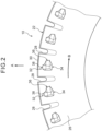
- Plural lug grooves 28 are formed in the tread 22 of the heavy duty tire 10 around the tire circumferential direction.
- the lug grooves 28 formed in the tread 22 extend further toward the tire width direction outer sides than the ground contact edges 22E of the tread 22.
- end portions of the lug grooves 28 open onto the buttress portions 26 of the heavy duty tire 10.
- land portions formed between lug grooves 28 that are adjacent in the tire circumferential direction are referred to as lug blocks 30.
- the concave air-cooling portions 32 are formed in the buttress portions 26.
- the air-cooling portions 32 are formed to side faces of the respective lug blocks 30 partitioned by the lug grooves 28 (to the buttress portion 26).
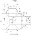
- each of the air-cooling portions 32 is configured including a recess portion 34, a first air entry and exit promotion portion 36 serving as an example of an air entry and exit promotion portion, and a second air entry and exit promotion portion 38.
- Each of the air entry and exit promotion portions is a location linked to a side portion of the recess portion 34 so as to be open toward the tire outside, and has a depth dimension from the tire surface that gradually increases on progression from the tire surface of the buttress portion 26 toward a bottom portion 40 of the recess portion 34.
- a combined surface area of slopes 46, 52 is greater than a surface area of the bottom portion 40 of the recess portion 34.
- the recess portion 34 As illustrated in Fig. 1 to Fig. 3 , the recess portions 34 are formed to the buttress portions 26 so as to open toward the tire outside. As illustrated in Fig. 4 , in plan view the recess portion 34 includes the bottom portion 40 that has a trapezoidal shape in which a bottom side 40A at the tire radial direction outer side (arrow A direction side) has a greater width than an upper side 40B at the tire radial direction inner side.
- bottom side 40A and the upper side 40B are parallel to a direction tangential to the tire circumferential direction (arrow B direction), and a side 40C of the bottom portion 40 at a tire rotation direction front (arrow B direction) side and a side 40D of the bottom portion 40 on the opposite side to the tire rotation direction front side are inclined with respect to the tire radial direction (arrow A direction).
- the bottom portion 40 is trapezoidal shaped in the present exemplary embodiment, the bottom portion 40 may be another polygonal shape such as a square, rectangular, or triangular shape, or may be circular or elliptical in shape.
- the bottom portion 40 is inclined such that its depth gradually becomes shallower on progression from the tire radial direction inner side toward the tire radial direction outer side (arrow A direction side) as illustrated in Fig. 5(B) .
- the bottom portion 40 may also be inclined with respect to a direction running along the tire rotation direction (arrow B direction).
- the bottom portion 40 may have a uniform depth in a direction running along the tire radial direction (arrow A).
- the bottom portion 40 is disposed at the tire width direction outer side of a tire width direction end portion 16Be of the protective belt 16B, this being formed with the maximum width in the belt 14.
- the tire width direction end portion 16Be of the protective belt 16B is positioned at the tire width direction inner side of a tire radial direction center portion of the recess portion 34. More specifically, the tire width direction end portion 16Be is disposed between the bottom side 40A and the upper side 40B of the bottom portion 40 (see Fig. 4 ) so as to be closer to the upper side 40B.
- a recess sidewall 42 configuring part of the recess portion 34 is formed on the opposite side of the bottom portion 40 to the tire rotation direction front (arrow B direction) side.
- a recess sidewall 44 configuring another part of the recess portion 34 is formed at the tire radial direction inner side of the bottom portion 40 (on the opposite side to the arrow A direction).
- the recess sidewall 42 is inclined with respect to a normal line HL that runs perpendicular to the surface of the buttress portion 26.
- a theoretical recess sidewall 43 is inclined at the same angle but in the opposite direction to the recess sidewall 42 on the tire rotation direction front (arrow B direction) side of the bottom portion 40.
- the recess sidewall 44 is also inclined with respect to a normal line HL that runs perpendicular to the surface of the buttress portion 26.
- a theoretical recess sidewall 45 is inclined at the same angle but in the opposite direction to the recess sidewall 44 at the tire radial direction outer (arrow A direction) side of the bottom portion 40. In such a configuration, the recess portion 34 would be formed so as to widen on progression from the bottom portion 40 toward the tire outside.
- the first air entry and exit promotion portion 36 is disposed at the tire rotation direction front (arrow B direction) side of the recess portion 34.
- the first air entry and exit promotion portion 36 has a trapezoidal shape in plan view, and is a concave portion including the slope 46 that is inclined from the surface of the buttress portion 26 at the tire rotation direction front side (arrow B direction side) toward the bottom portion 40 of the recess portion 34. Note that the slope 46 connects smoothly to the bottom portion 40.
- the slope 46 may be formed with another polygonal shape in plan view, depending on the inclination direction of the bottom portion 40 (the extension direction of the side 40C), and the surface profile of the buttress portion 26.
- the angle formed by the sidewall 48 with respect to the slope 46 is greater than the angle formed by the sidewall 50 with respect to the slope 46.
- a shortest distance along the slope 46 from the side 40C to the surface of the buttress portion 26 is longer than a shortest distance along the recess sidewall 42 from the side 40D to the surface of the buttress portion 26.
- the width of the first air entry and exit promotion portion 36 in the tire radial direction gradually increases on progression from the tire rotation direction front side toward the recess portion 34.
- W3 > W1 when W1 is the width of a tire rotation direction front side end portion of the first air entry and exit promotion portion 36
- W3 is the width of the first air entry and exit promotion portion 36 on the recess portion 34 side (the width of a portion connected to the recess portion 34 as measured along the tire radial direction).
- the width of the slope 46 is uniform, whereas the widths of the sidewalls 48, 50 gradually increase on progression from the tire rotation direction front side toward the recess portion 34.
- the width of the first air entry and exit promotion portion 36 may be uniform on progression from the tire rotation direction front side toward the recess portion 34.
- the width W3 of the first air entry and exit promotion portion 36 on the recess portion 34 side as measured at the tire surface is set so as to be the same as a (tire radial direction) width W2 of the recess portion 34 at the tire surface.
- the double-dotted dashed lines (imaginary lines) in Fig. 4 indicate the extent of the opening of the recess portion 34 were the first air entry and exit promotion portion 36 and the second air entry and exit promotion portion 38 not formed thereto.
- the slope 46 has a gentler incline than the recess sidewall 42 and the recess sidewall 44 of the recess portion 34.
- An average incline angle ⁇ 1 of the slope 46 with respect to the surface of the buttress portion 26 is no greater than 45°. If the average incline angle ⁇ 1 were greater than 45°, it would be difficult to redirect air flowing along the tire surface so as to follow the slope 46. Note that the average incline angle ⁇ 1 may be within a range of from 5° to 30°. If the average incline angle ⁇ 1 were smaller than 5°, the cooling effect would be diminished. Note that the average incline angle ⁇ 1 may be within a range of from 15° to 25°.
- the slope 46 forms a straight line running from the side 40C to the surface of the buttress portion 26. Due to forming a straight line in this manner, the slope 46 has a uniform incline angle, such that air inflow and outflow directions can be easily made to follow the slope 46.
- the second air entry and exit promotion portion 38 is disposed on the tire radial direction outer (arrow A direction) side of the recess portion 34.
- the second air entry and exit promotion portion 38 is a concave portion including the slope 52 that is inclined from the surface of the buttress portion 26 toward the bottom portion 40 of the recess portion 34.
- the slope 52 has a substantially square shape in plan view. The slope 52 connects smoothly to the bottom portion 40.
- the slope 52 has a substantially square shape in the present exemplary embodiment, the slope 52 may have another polygonal shape such as a rectangular or trapezoidal shape.
- a sidewall 54 that has a steeper incline that the slope 52 is formed at the tire rotation direction front side (arrow B direction side) of the slope 52, and a sidewall 56 that has a steeper incline than the slope 52 is formed at the tire rotation direction rear side of the slope 52.
- the angles formed by the sidewalls 54, 56 with respect to the slope 52 are substantially the same as one another.
- the width dimension (the dimension in a direction intersecting the incline direction of the slope 52) at the tire radial direction outer side is formed relatively smaller than the width dimension at the recess portion 34 side.
- a shortest distance along the slope 52 from the bottom side 40A to the surface of the buttress portion 26 is longer than a shortest distance along the recess sidewall 44 from the upper side 40B to the surface of the buttress portion 26.
- the width of the slope 52 is uniform from the bottom portion 40 of the recess portion 34 toward the tire radial direction outer side.
- end portions of the sidewall 54 of the second air entry and exit promotion portion 38 and the sidewall 48 of the first air entry and exit promotion portion 36 previously described are connected to one another.
- end portions of the sidewall 50 of the first air entry and exit promotion portion 36 and the recess sidewall 44 of the recess portion 34 are also connected to one another.
- the slope 52 has a gentler incline than the recess sidewall 42 and the recess sidewall 44 of the recess portion 34.
- an average incline angle ⁇ 2 of the slope 52 with respect to the surface of the buttress portion 26 is no greater than 45°. If the average incline angle ⁇ 2 were greater than 45°, it would be difficult to redirect air flowing along the tire surface so as to follow the slope 52. Note that the average incline angle ⁇ 2 may be within a range of from 5° to 30°. If the average incline angle ⁇ 2 were smaller than 5°, the cooling effect would be diminished. The average incline angle ⁇ 2 may be within a range of from 15° to 25°.
- the slope 52 forms a straight line running from the bottom side 40A to the surface of the buttress portion 26. Due to forming a straight line in this manner, the slope 52 has a uniform incline angle, such that air inflow and outflow directions can be easily made to follow the slope 52.
- the average incline angle ⁇ 1 of the slope 46 and the average incline angle ⁇ 2 of the slope 52 are both smaller than an average incline angle ⁇ 3 of the recess sidewall 42 and an average incline angle ⁇ 4 of the recess sidewall 44 of the recess portion 34.
- the average incline angles ⁇ 3, ⁇ 4 are both greater than the incline angles of the slopes 46, 52.
- the average incline angles ⁇ 3, ⁇ 4 are preferably both greater than 40°.
- the recess sidewall 44 and the recess sidewall 42 each have a rounded profile at a boundary with the surface of the buttress portion 26. This enables distortion of the buttress portion 26 under load to be suppressed.
- Fig. 5(C) is a cross-section of the air-cooling portion illustrated in Fig. 4 as sectioned along line 5C-5C.
- an end portion on the recess portion 34 side of the slope 46 of the first air entry and exit promotion portion 36 is linked to the entire side 40C at the tire rotation direction front side of the bottom portion 40 of the recess portion 34.
- an end portion on the recess portion 34 side of the slope 52 of the second air entry and exit promotion portion 38 is linked to the entire bottom side 40A at the tire radial direction outer side of the bottom portion 40 of the recess portion 34.
- the tread 22 As the heavy duty tire 10 rotates while traveling, the tread 22 repeatedly contacts and moves away from the road surface. The tread 22 therefore undergoes repeated distortion, thereby generating a large amount of heat, particularly at the buttress portion 26.
- the average incline angle ⁇ 1 of the slope 46 of the first air entry and exit promotion portion 36 with respect to the tire surface is no greater than 45°, and the slope 46 connects to the bottom portion 40 of the recess portion 34 at a gentler incline than the recess sidewall 42 and the recess sidewall 44 of the recess portion 34. This enables air at the tire rotation direction front side of the recess portion 34 to be smoothly directed along the slope 46 and into the recess portion 34. Moreover, the air that has flowed into the recess portion 34 flows along the bottom portion 40 of the recess portion 34, enabling the bottom portion 40 to be effectively cooled.
- the air-cooling portion 32 including the first air entry and exit promotion portion 36 promotes the inflow of air toward the recess portion 34 compared to cases in which the first air entry and exit promotion portion 36 is not present, enabling the buttress portion 26 to be more effectively cooled.
- the air flowing along the bottom portion 40 is then dispelled to the tire exterior along the slope 52 of the second air entry and exit promotion portion 38 disposed at the tire radial direction outer side of the recess portion 34, thereby enabling air that has flowed in from the tire rotation direction front side to be dispelled to the tire outside in turn.
- the air-cooling portion 32 promotes the inflow of air into the recess portion 34 compared to cases in which the second air entry and exit promotion portion 38 is not present, enabling the buttress portion 26 to be more effectively cooled.
- the air entry and exit promotion portions namely the first air entry and exit promotion portion 36 and the second air entry and exit promotion portion 38, are disposed at two locations in the present exemplary embodiment, thereby enabling openings for air to enter and exit the recess portion 34 to be secured, and thus enabling airflow to be improved.
- the recess portion 34 side end portion of the slope 46 of the first air entry and exit promotion portion 36 is linked to the entire side 40C at the tire rotation direction front side of the bottom portion 40 of the recess portion 34.
- the recess portion 34 side end portion of the slope 52 of the second air entry and exit promotion portion 38 is linked to the entire side 40A at the tire radial direction outer side of the bottom portion 40 of the recess portion 34.
- air flowing in through the first air entry and exit promotion portion 36 can be made to flow in across the entire width of the bottom portion 40 of the recess portion 34 and flow out through the second air entry and exit promotion portion 38, enabling the bottom portion 40 to be effectively cooled. Air can be also be made to efficiently flow in through the second air entry and exit promotion portion 38.
- the temperature of the tread 22 is liable to rise in the vicinity of the belt 14 where the width of the belt 14 is at its maximum, namely, in the vicinity of the tire width direction end portion 16Be of the protective belt 16B where the width of the belt 14 configuration is at its maximum.
- the bottom portion 40 of the recess portion 34 of the air-cooling portion 32 is disposed at the tire width direction outer side of the tire width direction end portion 16Be of the protective belt 16B, and is positioned near to the tire width direction end portion 16Be of the protective belt 16B where the temperature is most liable to rise. This enables heat generated near to the tire width direction end portion 16Be of the protective belt 16B to be effectively dissipated to the tire exterior through the bottom portion 40 of the recess portion 34, enabling the rise in temperature near to the tire width direction end portion 16Be of the maximum width protective belt 16B to be effectively suppressed.
- the tire width direction end portion 16Be of the protective belt 16B is positioned at the tire width direction inner side of the tire radial direction center portion of the bottom portion 40 of the recess portion 34, thereby enabling a tire radial direction inner side portion and tire radial direction outer side portion of the tire width direction end portion 16Be to be evenly cooled.
- the first air entry and exit promotion portion 36 is disposed at the tire rotation direction front side of the recess portion 34 and the second air entry and exit promotion portion 38 is disposed at the tire radial direction outer side of the recess portion 34 as examples of air entry and exit promotion portions in two or more locations.
- the placement and number of air entry and exit promotion portions are not limited thereto.
- FIGs. 6 are plan views schematically illustrating modified examples of the air-cooling portion 32, in which only the bottom portion of the recess portion 34 and the slopes of the air entry and exit promotion portions are illustrated.
- air entry and exit promotion portions are disposed at two locations at the two tire circumferential direction sides of the recess portion 34.
- a fourth air entry and exit promotion portion 76 is formed at the tire radial direction inner side of the recess portion 34. Namely, air entry and exit promotion portions are formed at three locations in this example.
- the second air entry and exit promotion portion 38 is formed in addition to the configuration of Fig. 6(B) . Namely, air entry and exit promotion portions are formed at four locations in this example.
- the first air entry and exit promotion portion 36 and the third air entry and exit promotion portion 66 are disposed at two locations at the two tire circumferential direction sides of the recess portion 34.
- the tire radial direction widths of the first air entry and exit promotion portion 36 and the third air entry and exit promotion portion 66 gradually increase on progression away from the recess portion 34.
- the tire width direction end portion 16Be of the belt ply (the protective belt 16B) where the width of the belt configuration is at its maximum is positioned at the tire width direction inner side of the bottom portion 40 of the recess portion 34
- the tire width direction end portion 16Be may be disposed at a position that is displaced slightly from the tire width direction inner side of the bottom portion 40 of the recess portion 34.
- the bottom portion 40 of the recess portion 34 is not positioned at the tire width direction outer side of a tire width direction end 16Ae of the protective belt 16A disposed at the tire radial direction outermost side of the belt 14 in the illustrated example, the bottom portion 40 may be extended toward the tire radial direction outer side such that the bottom portion 40 of the recess portion 34 is positioned at the tire width direction outer side of the tire width direction end 16Ae of the protective belt 16A at the outermost side.
- Cracks may develop at the surface of the tread 22 when the heavy duty tire 10 travels along rough roads or the like.
- heat is generated such that the temperature rises in the vicinity of the tire width direction end 16Ae of the protective belt 16A at the tire radial direction outermost side, the durability of the tread rubber 24 surrounding the vicinity of the tire width direction end 16Ae is reduced, and cracks that have developed on the surface of the tread 22 might advance toward the rubber portion where the durability is reduced.
- Disposing the bottom portion 40 of the recess portion 34 at the tire width direction outer side of the tire width direction end 16Ae of the protective belt 16A at the tire radial direction outermost side enables the bottom portion 40 to be brought closer to the tire width direction end 16Ae. This enables the rise in temperature near to the tire width direction end 16Ae to be suppressed, enabling the durability of the tread rubber 24 near to the tire width direction end 16Ae to be maintained, and enabling cracks at the surface of the tread 22 to be suppressed from advancing toward the tread rubber 24 near to the tire width direction end 16Ae.
- the combined surface area of the slopes 46, 52 is greater than the surface area of the bottom portion 40 of the recess portion 34 in the above exemplary embodiment, this combined surface area may be equal to or less than the surface area of the bottom portion 40 of the recess portion 34.
- the end portion of the first air entry and exit promotion portion 36 on the opposite side to the recess portion 34 side terminates at the tire surface of the buttress portion 26 in the above exemplary embodiment
- the end portion of the first air entry and exit promotion portion 36 on the opposite side to the recess portion 34 side may be linked to (open onto) a lug groove 28 (not illustrated in the drawings). This enables air in the lug groove 28 to be made to flow into the recess portion 34 in addition to air from the tire side face.
- the end portion of the second air entry and exit promotion portion 38 on the opposite side to the recess portion 34 side terminates at the tire surface of the buttress portion 26 in the above exemplary embodiment
- the end portion of the second air entry and exit promotion portion 38 on the opposite side to the recess portion 34 side may be linked to (open onto) a lug groove 28 or a tread end (not illustrated in the drawings).
Landscapes
- Engineering & Computer Science (AREA)
- Mechanical Engineering (AREA)
- Tires In General (AREA)
Claims (6)
- Pneumatique pour poids lourds (10), comprenant :une partie évidée (34) qui est formée dans une partie de contrefort (26) et qui s'ouvre vers un extérieur du pneumatique ; etdes parties de promotion d'entrée et de sortie d'air (36, 38, 66, 76), chacune d'entre elles étant reliée à une partie latérale de la partie évidée (34), qui est ouverte vers l'extérieur du pneumatique, et qui inclut une pente (46, 52), d'une surface du pneumatique vers une partie inférieure (40) de la partie évidée (34), de sorte qu'une dimension de profondeur est progressivement accrue depuis la surface du pneumatique ;un angle d'inclinaison moyen de la pente (46, 52) par rapport à la surface du pneumatique n'étant pas supérieur à 45° ; etles parties de promotion d'entrée et de sortie d'air (36, 38, 66, 76) étant disposées au niveau de deux ou de plusieurs emplacements,dans lequel les parties de promotion d'entrée et de sortie d'air (36 38, 66, 76) sont disposées au moins au niveau de deux emplacements correspondant à deux côtés, dans la direction circonférentielle du pneumatique, de la partie évidée (34).
- Pneumatique pour poids lourds (10) selon la revendication 1, dans lequel les parties de promotion d'entrée et de sortie d'air (36, 38, 66, 76) sont disposées au niveau de trois emplacements.
- Pneumatique pour poids lourds (10) selon la revendication 1, dans lequel les parties de promotion d'entrée et de sortie d'air (36, 38, 66, 76) sont disposées au niveau de quatre emplacements.
- Pneumatique pour poids lourds (10) selon l'une quelconque des revendications 1 à 3, dans lequel une partie d'extrémité, dans la direction de la largeur du pneumatique, d'un pli de ceinture à largeur maximale qui configure une ceinture est positionnée au niveau d'un côté interne, dans une direction de la largeur du pneumatique, de la partie inférieure (40) de la partie évidée (34).
- Pneumatique pour poids lourds (10) selon la revendication 4, dans lequel la partie d'extrémité (16Be), dans la direction de la largeur du pneumatique, du pli de ceinture à largeur maximale (16B) est positionnée au niveau du côté interne, dans la direction de la largeur du pneumatique, d'une partie centrale, dans la direction radiale du pneumatique, de la partie inférieure (40).
- Pneumatique pour poids lourds (10) selon l'une quelconque des revendications 1 à 5, dans lequel une zone de surface combinée des pentes (46, 52), vues dans une vue en plan, est plus grande qu'une zone de surface de la partie inférieure (40) de la partie évidée (34), vues dans une vue en plan.
Applications Claiming Priority (2)
| Application Number | Priority Date | Filing Date | Title |
|---|---|---|---|
| JP2017237700A JP2019104361A (ja) | 2017-12-12 | 2017-12-12 | 重荷重用タイヤ |
| PCT/JP2018/023000 WO2019116611A1 (fr) | 2017-12-12 | 2018-06-15 | Pneu poids lourd |
Publications (3)
| Publication Number | Publication Date |
|---|---|
| EP3725552A1 EP3725552A1 (fr) | 2020-10-21 |
| EP3725552A4 EP3725552A4 (fr) | 2021-08-25 |
| EP3725552B1 true EP3725552B1 (fr) | 2023-09-06 |
Family
ID=66819138
Family Applications (1)
| Application Number | Title | Priority Date | Filing Date |
|---|---|---|---|
| EP18888324.3A Active EP3725552B1 (fr) | 2017-12-12 | 2018-06-15 | Pneu poids lourd |
Country Status (5)
| Country | Link |
|---|---|
| US (1) | US20210170797A1 (fr) |
| EP (1) | EP3725552B1 (fr) |
| JP (1) | JP2019104361A (fr) |
| CN (1) | CN111479704A (fr) |
| WO (1) | WO2019116611A1 (fr) |
Family Cites Families (12)
| Publication number | Priority date | Publication date | Assignee | Title |
|---|---|---|---|---|
| US2972368A (en) * | 1958-05-26 | 1961-02-21 | Dayco Corp | Vehicle tire |
| JPH01145206A (ja) * | 1987-11-30 | 1989-06-07 | Sumitomo Rubber Ind Ltd | 空気入りタイヤ |
| JP2000103206A (ja) * | 1998-09-29 | 2000-04-11 | Bridgestone Corp | 空気入りタイヤ |
| JP2004066851A (ja) * | 2002-08-01 | 2004-03-04 | Bridgestone Corp | 空気入りタイヤ |
| US20110290388A1 (en) | 2006-07-13 | 2011-12-01 | Radulescu Robert C | Tire with side features for resisting irregular shoulder wear |
| JP4843661B2 (ja) * | 2008-10-28 | 2011-12-21 | 住友ゴム工業株式会社 | 重荷重用タイヤ |
| JP2010132045A (ja) * | 2008-12-02 | 2010-06-17 | Bridgestone Corp | タイヤ |
| JP2010280322A (ja) * | 2009-06-05 | 2010-12-16 | Sumitomo Rubber Ind Ltd | 空気入りタイヤ |
| AU2012341419B2 (en) * | 2011-11-22 | 2015-08-13 | Bridgestone Corporation | Tire |
| JP2015034004A (ja) * | 2013-08-08 | 2015-02-19 | クムホ タイヤ カンパニー インコーポレーテッド | 冷却ピンのピッチ決定方法およびこれを用いた空気入りタイヤ |
| JP6735131B2 (ja) * | 2015-07-10 | 2020-08-05 | 株式会社ブリヂストン | タイヤ |
| JP6941415B2 (ja) * | 2015-10-06 | 2021-09-29 | 横浜ゴム株式会社 | 空気入りタイヤ |
-
2017
- 2017-12-12 JP JP2017237700A patent/JP2019104361A/ja active Pending
-
2018
- 2018-06-15 WO PCT/JP2018/023000 patent/WO2019116611A1/fr not_active Ceased
- 2018-06-15 CN CN201880080031.9A patent/CN111479704A/zh active Pending
- 2018-06-15 US US16/770,950 patent/US20210170797A1/en not_active Abandoned
- 2018-06-15 EP EP18888324.3A patent/EP3725552B1/fr active Active
Also Published As
| Publication number | Publication date |
|---|---|
| JP2019104361A (ja) | 2019-06-27 |
| CN111479704A (zh) | 2020-07-31 |
| WO2019116611A1 (fr) | 2019-06-20 |
| US20210170797A1 (en) | 2021-06-10 |
| EP3725552A1 (fr) | 2020-10-21 |
| EP3725552A4 (fr) | 2021-08-25 |
Similar Documents
| Publication | Publication Date | Title |
|---|---|---|
| JP2003211917A (ja) | 二輪車用空気入りタイヤ | |
| US20140116590A1 (en) | Heavy Duty Tire | |
| WO2016167122A1 (fr) | Pneu à affaissement limité | |
| EP2799254B1 (fr) | Pneu | |
| US12151513B2 (en) | Pneumatic tire | |
| CN107148362A (zh) | 充气轮胎 | |
| JP5498245B2 (ja) | タイヤ | |
| EP3725553B1 (fr) | Pneu pour fortes charges | |
| EP3725552B1 (fr) | Pneu poids lourd | |
| US20190176539A1 (en) | Pneumatic tire | |
| EP3725554B1 (fr) | Pneu à usage intensif | |
| JP5966348B2 (ja) | 空気入りタイヤ | |
| US20190176530A1 (en) | Pneumatic tire | |
| EP3725551B1 (fr) | Pneu à usage intensif | |
| US11964513B2 (en) | Tire | |
| JP7074586B2 (ja) | 空気入りタイヤ | |
| JP5803163B2 (ja) | 空気入りタイヤ | |
| JP2019104362A (ja) | 重荷重用タイヤ | |
| JPWO2019116626A1 (ja) | 重荷重用タイヤ | |
| CN107735268A (zh) | 轮胎 |
Legal Events
| Date | Code | Title | Description |
|---|---|---|---|
| STAA | Information on the status of an ep patent application or granted ep patent |
Free format text: STATUS: THE INTERNATIONAL PUBLICATION HAS BEEN MADE |
|
| PUAI | Public reference made under article 153(3) epc to a published international application that has entered the european phase |
Free format text: ORIGINAL CODE: 0009012 |
|
| STAA | Information on the status of an ep patent application or granted ep patent |
Free format text: STATUS: REQUEST FOR EXAMINATION WAS MADE |
|
| 17P | Request for examination filed |
Effective date: 20200611 |
|
| AK | Designated contracting states |
Kind code of ref document: A1 Designated state(s): AL AT BE BG CH CY CZ DE DK EE ES FI FR GB GR HR HU IE IS IT LI LT LU LV MC MK MT NL NO PL PT RO RS SE SI SK SM TR |
|
| AX | Request for extension of the european patent |
Extension state: BA ME |
|
| DAV | Request for validation of the european patent (deleted) | ||
| DAX | Request for extension of the european patent (deleted) | ||
| A4 | Supplementary search report drawn up and despatched |
Effective date: 20210726 |
|
| RIC1 | Information provided on ipc code assigned before grant |
Ipc: B60C 11/01 20060101AFI20210720BHEP Ipc: B60C 9/18 20060101ALI20210720BHEP Ipc: B60C 11/00 20060101ALI20210720BHEP |
|
| GRAP | Despatch of communication of intention to grant a patent |
Free format text: ORIGINAL CODE: EPIDOSNIGR1 |
|
| STAA | Information on the status of an ep patent application or granted ep patent |
Free format text: STATUS: GRANT OF PATENT IS INTENDED |
|
| INTG | Intention to grant announced |
Effective date: 20230406 |
|
| P01 | Opt-out of the competence of the unified patent court (upc) registered |
Effective date: 20230529 |
|
| GRAS | Grant fee paid |
Free format text: ORIGINAL CODE: EPIDOSNIGR3 |
|
| GRAA | (expected) grant |
Free format text: ORIGINAL CODE: 0009210 |
|
| STAA | Information on the status of an ep patent application or granted ep patent |
Free format text: STATUS: THE PATENT HAS BEEN GRANTED |
|
| AK | Designated contracting states |
Kind code of ref document: B1 Designated state(s): AL AT BE BG CH CY CZ DE DK EE ES FI FR GB GR HR HU IE IS IT LI LT LU LV MC MK MT NL NO PL PT RO RS SE SI SK SM TR |
|
| REG | Reference to a national code |
Ref country code: GB Ref legal event code: FG4D |
|
| REG | Reference to a national code |
Ref country code: CH Ref legal event code: EP |
|
| REG | Reference to a national code |
Ref country code: IE Ref legal event code: FG4D |
|
| REG | Reference to a national code |
Ref country code: DE Ref legal event code: R096 Ref document number: 602018057246 Country of ref document: DE |
|
| REG | Reference to a national code |
Ref country code: LT Ref legal event code: MG9D |
|
| REG | Reference to a national code |
Ref country code: NL Ref legal event code: MP Effective date: 20230906 |
|
| PG25 | Lapsed in a contracting state [announced via postgrant information from national office to epo] |
Ref country code: GR Free format text: LAPSE BECAUSE OF FAILURE TO SUBMIT A TRANSLATION OF THE DESCRIPTION OR TO PAY THE FEE WITHIN THE PRESCRIBED TIME-LIMIT Effective date: 20231207 |
|
| PG25 | Lapsed in a contracting state [announced via postgrant information from national office to epo] |
Ref country code: SE Free format text: LAPSE BECAUSE OF FAILURE TO SUBMIT A TRANSLATION OF THE DESCRIPTION OR TO PAY THE FEE WITHIN THE PRESCRIBED TIME-LIMIT Effective date: 20230906 Ref country code: RS Free format text: LAPSE BECAUSE OF FAILURE TO SUBMIT A TRANSLATION OF THE DESCRIPTION OR TO PAY THE FEE WITHIN THE PRESCRIBED TIME-LIMIT Effective date: 20230906 Ref country code: NO Free format text: LAPSE BECAUSE OF FAILURE TO SUBMIT A TRANSLATION OF THE DESCRIPTION OR TO PAY THE FEE WITHIN THE PRESCRIBED TIME-LIMIT Effective date: 20231206 Ref country code: LV Free format text: LAPSE BECAUSE OF FAILURE TO SUBMIT A TRANSLATION OF THE DESCRIPTION OR TO PAY THE FEE WITHIN THE PRESCRIBED TIME-LIMIT Effective date: 20230906 Ref country code: LT Free format text: LAPSE BECAUSE OF FAILURE TO SUBMIT A TRANSLATION OF THE DESCRIPTION OR TO PAY THE FEE WITHIN THE PRESCRIBED TIME-LIMIT Effective date: 20230906 Ref country code: HR Free format text: LAPSE BECAUSE OF FAILURE TO SUBMIT A TRANSLATION OF THE DESCRIPTION OR TO PAY THE FEE WITHIN THE PRESCRIBED TIME-LIMIT Effective date: 20230906 Ref country code: GR Free format text: LAPSE BECAUSE OF FAILURE TO SUBMIT A TRANSLATION OF THE DESCRIPTION OR TO PAY THE FEE WITHIN THE PRESCRIBED TIME-LIMIT Effective date: 20231207 Ref country code: FI Free format text: LAPSE BECAUSE OF FAILURE TO SUBMIT A TRANSLATION OF THE DESCRIPTION OR TO PAY THE FEE WITHIN THE PRESCRIBED TIME-LIMIT Effective date: 20230906 |
|
| REG | Reference to a national code |
Ref country code: AT Ref legal event code: MK05 Ref document number: 1608068 Country of ref document: AT Kind code of ref document: T Effective date: 20230906 |
|
| PG25 | Lapsed in a contracting state [announced via postgrant information from national office to epo] |
Ref country code: NL Free format text: LAPSE BECAUSE OF FAILURE TO SUBMIT A TRANSLATION OF THE DESCRIPTION OR TO PAY THE FEE WITHIN THE PRESCRIBED TIME-LIMIT Effective date: 20230906 |
|
| PG25 | Lapsed in a contracting state [announced via postgrant information from national office to epo] |
Ref country code: IS Free format text: LAPSE BECAUSE OF FAILURE TO SUBMIT A TRANSLATION OF THE DESCRIPTION OR TO PAY THE FEE WITHIN THE PRESCRIBED TIME-LIMIT Effective date: 20240106 |
|
| PG25 | Lapsed in a contracting state [announced via postgrant information from national office to epo] |
Ref country code: AT Free format text: LAPSE BECAUSE OF FAILURE TO SUBMIT A TRANSLATION OF THE DESCRIPTION OR TO PAY THE FEE WITHIN THE PRESCRIBED TIME-LIMIT Effective date: 20230906 |
|
| PG25 | Lapsed in a contracting state [announced via postgrant information from national office to epo] |
Ref country code: ES Free format text: LAPSE BECAUSE OF FAILURE TO SUBMIT A TRANSLATION OF THE DESCRIPTION OR TO PAY THE FEE WITHIN THE PRESCRIBED TIME-LIMIT Effective date: 20230906 |
|
| PG25 | Lapsed in a contracting state [announced via postgrant information from national office to epo] |
Ref country code: SM Free format text: LAPSE BECAUSE OF FAILURE TO SUBMIT A TRANSLATION OF THE DESCRIPTION OR TO PAY THE FEE WITHIN THE PRESCRIBED TIME-LIMIT Effective date: 20230906 Ref country code: RO Free format text: LAPSE BECAUSE OF FAILURE TO SUBMIT A TRANSLATION OF THE DESCRIPTION OR TO PAY THE FEE WITHIN THE PRESCRIBED TIME-LIMIT Effective date: 20230906 Ref country code: IS Free format text: LAPSE BECAUSE OF FAILURE TO SUBMIT A TRANSLATION OF THE DESCRIPTION OR TO PAY THE FEE WITHIN THE PRESCRIBED TIME-LIMIT Effective date: 20240106 Ref country code: ES Free format text: LAPSE BECAUSE OF FAILURE TO SUBMIT A TRANSLATION OF THE DESCRIPTION OR TO PAY THE FEE WITHIN THE PRESCRIBED TIME-LIMIT Effective date: 20230906 Ref country code: EE Free format text: LAPSE BECAUSE OF FAILURE TO SUBMIT A TRANSLATION OF THE DESCRIPTION OR TO PAY THE FEE WITHIN THE PRESCRIBED TIME-LIMIT Effective date: 20230906 Ref country code: CZ Free format text: LAPSE BECAUSE OF FAILURE TO SUBMIT A TRANSLATION OF THE DESCRIPTION OR TO PAY THE FEE WITHIN THE PRESCRIBED TIME-LIMIT Effective date: 20230906 Ref country code: AT Free format text: LAPSE BECAUSE OF FAILURE TO SUBMIT A TRANSLATION OF THE DESCRIPTION OR TO PAY THE FEE WITHIN THE PRESCRIBED TIME-LIMIT Effective date: 20230906 Ref country code: PT Free format text: LAPSE BECAUSE OF FAILURE TO SUBMIT A TRANSLATION OF THE DESCRIPTION OR TO PAY THE FEE WITHIN THE PRESCRIBED TIME-LIMIT Effective date: 20240108 Ref country code: SK Free format text: LAPSE BECAUSE OF FAILURE TO SUBMIT A TRANSLATION OF THE DESCRIPTION OR TO PAY THE FEE WITHIN THE PRESCRIBED TIME-LIMIT Effective date: 20230906 |
|
| PG25 | Lapsed in a contracting state [announced via postgrant information from national office to epo] |
Ref country code: PL Free format text: LAPSE BECAUSE OF FAILURE TO SUBMIT A TRANSLATION OF THE DESCRIPTION OR TO PAY THE FEE WITHIN THE PRESCRIBED TIME-LIMIT Effective date: 20230906 Ref country code: IT Free format text: LAPSE BECAUSE OF FAILURE TO SUBMIT A TRANSLATION OF THE DESCRIPTION OR TO PAY THE FEE WITHIN THE PRESCRIBED TIME-LIMIT Effective date: 20230906 |
|
| REG | Reference to a national code |
Ref country code: DE Ref legal event code: R097 Ref document number: 602018057246 Country of ref document: DE |
|
| PG25 | Lapsed in a contracting state [announced via postgrant information from national office to epo] |
Ref country code: DK Free format text: LAPSE BECAUSE OF FAILURE TO SUBMIT A TRANSLATION OF THE DESCRIPTION OR TO PAY THE FEE WITHIN THE PRESCRIBED TIME-LIMIT Effective date: 20230906 |
|
| PLBE | No opposition filed within time limit |
Free format text: ORIGINAL CODE: 0009261 |
|
| STAA | Information on the status of an ep patent application or granted ep patent |
Free format text: STATUS: NO OPPOSITION FILED WITHIN TIME LIMIT |
|
| PG25 | Lapsed in a contracting state [announced via postgrant information from national office to epo] |
Ref country code: DK Free format text: LAPSE BECAUSE OF FAILURE TO SUBMIT A TRANSLATION OF THE DESCRIPTION OR TO PAY THE FEE WITHIN THE PRESCRIBED TIME-LIMIT Effective date: 20230906 Ref country code: SI Free format text: LAPSE BECAUSE OF FAILURE TO SUBMIT A TRANSLATION OF THE DESCRIPTION OR TO PAY THE FEE WITHIN THE PRESCRIBED TIME-LIMIT Effective date: 20230906 |
|
| 26N | No opposition filed |
Effective date: 20240607 |
|
| PG25 | Lapsed in a contracting state [announced via postgrant information from national office to epo] |
Ref country code: BG Free format text: LAPSE BECAUSE OF FAILURE TO SUBMIT A TRANSLATION OF THE DESCRIPTION OR TO PAY THE FEE WITHIN THE PRESCRIBED TIME-LIMIT Effective date: 20230906 |
|
| PG25 | Lapsed in a contracting state [announced via postgrant information from national office to epo] |
Ref country code: BG Free format text: LAPSE BECAUSE OF FAILURE TO SUBMIT A TRANSLATION OF THE DESCRIPTION OR TO PAY THE FEE WITHIN THE PRESCRIBED TIME-LIMIT Effective date: 20230906 |
|
| PG25 | Lapsed in a contracting state [announced via postgrant information from national office to epo] |
Ref country code: MC Free format text: LAPSE BECAUSE OF FAILURE TO SUBMIT A TRANSLATION OF THE DESCRIPTION OR TO PAY THE FEE WITHIN THE PRESCRIBED TIME-LIMIT Effective date: 20230906 |
|
| REG | Reference to a national code |
Ref country code: CH Ref legal event code: PL |
|
| PG25 | Lapsed in a contracting state [announced via postgrant information from national office to epo] |
Ref country code: LU Free format text: LAPSE BECAUSE OF NON-PAYMENT OF DUE FEES Effective date: 20240615 |
|
| GBPC | Gb: european patent ceased through non-payment of renewal fee |
Effective date: 20240615 |
|
| PG25 | Lapsed in a contracting state [announced via postgrant information from national office to epo] |
Ref country code: IE Free format text: LAPSE BECAUSE OF NON-PAYMENT OF DUE FEES Effective date: 20240615 |
|
| PG25 | Lapsed in a contracting state [announced via postgrant information from national office to epo] |
Ref country code: BE Free format text: LAPSE BECAUSE OF NON-PAYMENT OF DUE FEES Effective date: 20240630 Ref country code: CH Free format text: LAPSE BECAUSE OF NON-PAYMENT OF DUE FEES Effective date: 20240630 |
|
| PG25 | Lapsed in a contracting state [announced via postgrant information from national office to epo] |
Ref country code: GB Free format text: LAPSE BECAUSE OF NON-PAYMENT OF DUE FEES Effective date: 20240615 |
|
| REG | Reference to a national code |
Ref country code: BE Ref legal event code: MM Effective date: 20240630 |
|
| PGFP | Annual fee paid to national office [announced via postgrant information from national office to epo] |
Ref country code: DE Payment date: 20250618 Year of fee payment: 8 |
|
| PGFP | Annual fee paid to national office [announced via postgrant information from national office to epo] |
Ref country code: FR Payment date: 20250626 Year of fee payment: 8 |
|
| PG25 | Lapsed in a contracting state [announced via postgrant information from national office to epo] |
Ref country code: CY Free format text: LAPSE BECAUSE OF FAILURE TO SUBMIT A TRANSLATION OF THE DESCRIPTION OR TO PAY THE FEE WITHIN THE PRESCRIBED TIME-LIMIT; INVALID AB INITIO Effective date: 20180615 |
|
| PG25 | Lapsed in a contracting state [announced via postgrant information from national office to epo] |
Ref country code: HU Free format text: LAPSE BECAUSE OF FAILURE TO SUBMIT A TRANSLATION OF THE DESCRIPTION OR TO PAY THE FEE WITHIN THE PRESCRIBED TIME-LIMIT; INVALID AB INITIO Effective date: 20180615 |