EP3724740B1 - Thermostatventil - Google Patents
Thermostatventil Download PDFInfo
- Publication number
- EP3724740B1 EP3724740B1 EP18839820.0A EP18839820A EP3724740B1 EP 3724740 B1 EP3724740 B1 EP 3724740B1 EP 18839820 A EP18839820 A EP 18839820A EP 3724740 B1 EP3724740 B1 EP 3724740B1
- Authority
- EP
- European Patent Office
- Prior art keywords
- outlet
- skirt
- hollow body
- thermostatic valve
- opening
- Prior art date
- Legal status (The legal status is an assumption and is not a legal conclusion. Google has not performed a legal analysis and makes no representation as to the accuracy of the status listed.)
- Active
Links
Images


Classifications
-
- G—PHYSICS
- G05—CONTROLLING; REGULATING
- G05D—SYSTEMS FOR CONTROLLING OR REGULATING NON-ELECTRIC VARIABLES
- G05D23/00—Control of temperature
- G05D23/01—Control of temperature without auxiliary power
- G05D23/02—Control of temperature without auxiliary power with sensing element expanding and contracting in response to changes of temperature
- G05D23/021—Control of temperature without auxiliary power with sensing element expanding and contracting in response to changes of temperature the sensing element being a non-metallic solid, e.g. elastomer, paste
- G05D23/022—Control of temperature without auxiliary power with sensing element expanding and contracting in response to changes of temperature the sensing element being a non-metallic solid, e.g. elastomer, paste the sensing element being placed within a regulating fluid flow
-
- F—MECHANICAL ENGINEERING; LIGHTING; HEATING; WEAPONS; BLASTING
- F01—MACHINES OR ENGINES IN GENERAL; ENGINE PLANTS IN GENERAL; STEAM ENGINES
- F01P—COOLING OF MACHINES OR ENGINES IN GENERAL; COOLING OF INTERNAL-COMBUSTION ENGINES
- F01P7/00—Controlling of coolant flow
- F01P7/14—Controlling of coolant flow the coolant being liquid
- F01P7/16—Controlling of coolant flow the coolant being liquid by thermostatic control
- F01P7/167—Controlling of coolant flow the coolant being liquid by thermostatic control by adjusting the pre-set temperature according to engine parameters, e.g. engine load, engine speed
-
- F—MECHANICAL ENGINEERING; LIGHTING; HEATING; WEAPONS; BLASTING
- F16—ENGINEERING ELEMENTS AND UNITS; GENERAL MEASURES FOR PRODUCING AND MAINTAINING EFFECTIVE FUNCTIONING OF MACHINES OR INSTALLATIONS; THERMAL INSULATION IN GENERAL
- F16K—VALVES; TAPS; COCKS; ACTUATING-FLOATS; DEVICES FOR VENTING OR AERATING
- F16K1/00—Lift valves or globe valves, i.e. cut-off apparatus with closure members having at least a component of their opening and closing motion perpendicular to the closing faces
- F16K1/32—Details
- F16K1/34—Cutting-off parts, e.g. valve members, seats
- F16K1/36—Valve members
- F16K1/38—Valve members of conical shape
- F16K1/385—Valve members of conical shape contacting in the closed position, over a substantial axial length, a seat surface having the same inclination
-
- F—MECHANICAL ENGINEERING; LIGHTING; HEATING; WEAPONS; BLASTING
- F16—ENGINEERING ELEMENTS AND UNITS; GENERAL MEASURES FOR PRODUCING AND MAINTAINING EFFECTIVE FUNCTIONING OF MACHINES OR INSTALLATIONS; THERMAL INSULATION IN GENERAL
- F16K—VALVES; TAPS; COCKS; ACTUATING-FLOATS; DEVICES FOR VENTING OR AERATING
- F16K11/00—Multiple-way valves, e.g. mixing valves; Pipe fittings incorporating such valves
- F16K11/02—Multiple-way valves, e.g. mixing valves; Pipe fittings incorporating such valves with all movable sealing faces moving as one unit
-
- F—MECHANICAL ENGINEERING; LIGHTING; HEATING; WEAPONS; BLASTING
- F16—ENGINEERING ELEMENTS AND UNITS; GENERAL MEASURES FOR PRODUCING AND MAINTAINING EFFECTIVE FUNCTIONING OF MACHINES OR INSTALLATIONS; THERMAL INSULATION IN GENERAL
- F16K—VALVES; TAPS; COCKS; ACTUATING-FLOATS; DEVICES FOR VENTING OR AERATING
- F16K3/00—Gate valves or sliding valves, i.e. cut-off apparatus with closing members having a sliding movement along the seat for opening and closing
- F16K3/22—Gate valves or sliding valves, i.e. cut-off apparatus with closing members having a sliding movement along the seat for opening and closing with sealing faces shaped as surfaces of solids of revolution
- F16K3/24—Gate valves or sliding valves, i.e. cut-off apparatus with closing members having a sliding movement along the seat for opening and closing with sealing faces shaped as surfaces of solids of revolution with cylindrical valve members
-
- F—MECHANICAL ENGINEERING; LIGHTING; HEATING; WEAPONS; BLASTING
- F16—ENGINEERING ELEMENTS AND UNITS; GENERAL MEASURES FOR PRODUCING AND MAINTAINING EFFECTIVE FUNCTIONING OF MACHINES OR INSTALLATIONS; THERMAL INSULATION IN GENERAL
- F16K—VALVES; TAPS; COCKS; ACTUATING-FLOATS; DEVICES FOR VENTING OR AERATING
- F16K31/00—Actuating devices; Operating means; Releasing devices
- F16K31/002—Actuating devices; Operating means; Releasing devices actuated by temperature variation
-
- F—MECHANICAL ENGINEERING; LIGHTING; HEATING; WEAPONS; BLASTING
- F01—MACHINES OR ENGINES IN GENERAL; ENGINE PLANTS IN GENERAL; STEAM ENGINES
- F01P—COOLING OF MACHINES OR ENGINES IN GENERAL; COOLING OF INTERNAL-COMBUSTION ENGINES
- F01P7/00—Controlling of coolant flow
- F01P7/14—Controlling of coolant flow the coolant being liquid
- F01P2007/146—Controlling of coolant flow the coolant being liquid using valves
Definitions
- the present invention relates to the field of thermostatic valves.
- a thermostatic valve is typically used in the field of automatic thermal regulation for fluid circuits (gas, water, oil, etc.).
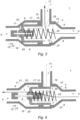
- a thermostatic valve comprises a closed hollow body 100 pierced with an inlet opening 101, a main outlet 102, a bypass outlet 103 and comprising a shutter 104 alternately separating the inlet opening 101 from the main outlet 102 or the bypass outlet 103, in a sealed manner.
- the shutter is sensitive to the temperature of the fluid so as to open above a threshold temperature and to close below said threshold temperature.
- An illustrative application in the automotive field is the production of water inlet boxes (convergent) or water outlet boxes (divergent).
- the shutter of a thermostatic valve typically comprises a thermostatic actuator, such as a wax capsule, and a shutter actuated by the thermostatic actuator.
- the wax capsule includes a cylinder filled with a temperature sensitive wax. The wax pushes back a rod under the effect of a significant change in volume accompanying a solid/liquid phase change, occurring at a threshold temperature or opening start temperature.
- the shutter can also be provided with a skirt, as described in the documents EP 2 132 468 , WO 2017/155483 , CN 102 425 687 And US 2015/315941 .
- the document EP 2 132 468 relates to a thermostatic valve according to the preamble of claim 1.
- the main outlet 102 and the bypass outlet 103 are aligned.
- the shutter 104 slides axially to alternately close one or the other of the outlets. According to this arrangement, the shutter is always resting against the mouth of one of the outlets to close it.
- Such an arrangement is advantageous in that it is easy to seal such a shutter.
- significant heat can increase the expansion of the wax capsule beyond the travel possible for the flap. In this case, the shutter risks forcing against the walls of the hollow body, and being damaged.
- a known solution consists of integrating an elastic device making it possible to absorb the overtravel of the wax capsule. However, this entails additional costs due to the manufacturing of the various elements (shutters, guide rod and overtravel spring) and additional bulk.
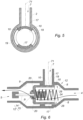
- the shutter is arranged perpendicular to the axis of the thermostatic actuator.
- Such an arrangement is advantageous in that it is easy to seal such a shutter at a reasonable cost.
- a disadvantage is that if there is a difference between the pressures applied on one side and on the other side of the shutter, that the thermostatic actuator must, when opening the valve, develop an additional effort in order to overcome this pressure difference. This necessary additional effort introduces a delay in opening equivalent to an increase in the threshold temperature. Also the thermostatic valve presents a sensitivity to the differential pressure modifying its threshold temperature.
- a solution known from the document WO 2017/155483 consists of using a hollow body in which the main outlet and the bypass outlet are radial.
- this device uses differential pressure to seal the blocking of an outlet by the valve.
- the valve is made up of several parts, which makes its manufacture complex and expensive.
- the invention relates to a thermostatic valve comprising a closed hollow body, a first opening opening into the hollow body, called the inlet opening, a second opening opening into the hollow body, called the main outlet, a third opening, substantially perpendicular to the second opening, opening into the hollow body, called the bypass outlet, and a shutter making it possible to alternately separate the intake opening from the main outlet or the bypass outlet.
- the shutter comprises a thermostatic actuator and a plastic skirt having at least one window adapted to be passed through by a fluid.
- the skirt is adapted to slide in the hollow body, along an axis substantially coincident with the axis of the thermostatic actuator, between a first position in which the skirt closes the main outlet, so that the fluid circulates between the opening of the inlet and the bypass outlet, a second position in which the skirt releases the main outlet and closes the bypass outlet, so that the fluid from the inlet opening can pass through the window and flow into the outlet main, and a third overtravel position in which a portion of the skirt is positioned in an overtravel zone of the hollow body and in which the skirt releases the main outlet and closes the bypass outlet.
- the skirt makes it possible to close outlets perpendicular to each other.
- This arrangement makes it possible to overcome the problems of overtraveling the wax capsule. Indeed, in the event of overtravel of the wax capsule, the skirt can move in the hollow body, in the overtravel zone while maintaining the seal of the shutter of the bypass outlet and without being compressed against the mouth of a fluid outlet.
- the relative flexibility of the plastic skirt advantageously makes it possible to use the pressure differences inside the hollow body to seal the shutter in the first or second position.
- the thermostatic valve according to the invention has a simple structure, comprising a reduced number of elements, achievable at low cost, compared to existing thermostatic valves which use expensive elastic devices.
- the invention proposes a thermostatic valve insensitive to overtravel of the wax capsule and at low cost.
- the skirt comprises a substantially circular bottom wall and a cylindrical side wall in which said at least one window is provided.
- the bottom wall is adapted to block the main outlet and the side wall is adapted to block the diversion outlet.
- the hollow body comprises at least one shoulder positioned at the mouth of the diversion outlet, to ensure a static seal with the side wall of the skirt when the skirt is in the second position.
- the mouth of the main outlet has a conical wall.
- the bottom wall of the skirt has a chamfer adapted to rest against the conical wall.
- the side wall of the skirt has two windows.
- the two windows can be diametrically opposed.
- thermostatic actuator passes through the bottom wall of the skirt.
- the hollow body may comprise a fourth opening, called a heating outlet, adapted to be closed by the skirt in the second position.
- the heating outlet and the bypass outlet can be positioned in the hollow body at distinct axial dimensions.
- the hollow body may comprise a fifth opening, called the air heater outlet, the air heater outlet being adapted to be closed by the skirt in the second position.
- the unit heater outlet can be positioned along an axis distinct from the longitudinal axis of the diversion outlet, so that the skirt seals or releases the unit heater outlet and the diversion outlet separately.
- the unit heater outlet and the bypass outlet can be positioned in the hollow body at distinct axial dimensions.
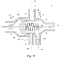
- the invention relates to a thermostatic valve 1 which comprises a closed hollow body 2.
- the hollow body 2 has three through openings: a first opening called the inlet opening 4, a second opening called the main outlet 5 generally connected to a radiator and a third opening called the bypass outlet 7 generally connected to a return circuit to the motor.
- the inlet opening 4 and the main outlet 5 are opposite each other, substantially coaxial.
- the bypass outlet 7 is positioned between the inlet opening 4 and the main outlet 5, perpendicular to these two openings.
- the radial positioning of the bypass outlet 7 is a particularly advantageous arrangement of the invention.
- the mouth of the inlet opening 4 may have a conical wall 8.
- the mouth of the main outlet 5 has a conical wall 9.
- the hollow body 2 comprises two annular ribs 10 positioned at the mouth of the bypass outlet 7. The function of the annular ribs 10 will be presented later.
- the hollow body 2 has a fourth opening called the reheating outlet 6.
- the reheating outlet 6 and the diversion outlet 7 are positioned in the hollow body 2 at distinct axial dimensions.
- the offset between the reheating outlet 6 and the bypass outlet 7 can be achieved by shifting the longitudinal axes 61 and 71 respective of the reheating outlet 6 and the bypass outlet 7.
- the offset can also be obtained by using outlets of different diameters.
- the hollow body 2 has a fifth opening called the air heater outlet 30.
- the air heater outlet 30 and the bypass outlet 7 are positioned in the hollow body 2 at distinct axial dimensions.
- the offset between the unit heater outlet 30 and the bypass outlet 7 can be achieved by shifting the respective longitudinal axes 31 and 71 of the unit heater outlet 30 and the bypass outlet 7. The shift can also be obtained by using outlets of different diameters.
- the thermostatic valve 1 comprises a shutter 11.
- the shutter 11 comprises a thermostatic actuator 12 and a skirt 13 made of plastic material.
- the thermostatic actuator 12 comprises a rod 14 fixed by a first end to the hollow body 2, at the mouth of the main outlet 5.
- a wax capsule 15 is positioned at the second end of the rod 14 .
- the skirt 13 comprises a substantially circular bottom wall 16 and a cylindrical side wall 17. According to the embodiments presented here, with reference to the figure 5 , the side wall 17 has two windows 19. According to other embodiments, the side wall 17 could have a different number of windows 19.
- the two windows 19 are diametrically opposed. As will be developed later, this technical arrangement allows the skirt 13 to close the bypass outlet 7 while allowing a fluid to pass through the windows 19 to flow into the main outlet 5.
- the bottom wall 16 has a chamfer 20 adapted to bear against the conical wall 9 of the mouth of the main outlet 5.
- the bottom wall 16 is crossed by the wax capsule 15.
- the wax capsule 15 is fixed to the bottom wall 16 in such a way that an expansion of the wax capsule 15 causes a translation of the skirt 13.
- the skirt 13 is movable in translation in the hollow body 2, between several positions.
- the shutter 11 also includes a return spring 24, bearing against the bottom wall 16 and against the mouth of the inlet opening 4.
- thermostatic valve 1 In conditions of use, in a vehicle, the thermostatic valve 1 can be connected to the cooling circuit of the vehicle's engine. Valve thermostatic 1 then makes it possible to direct the coolant, generally brine, according to its temperature and therefore the operating temperature of the engine.
- the coolant In the initial state, when the engine is started, the coolant is cold, at room temperature.
- the fluid flows through the inlet opening 4 and comes into contact with the wax capsule 15.
- the temperature of the fluid causes the wax capsule 15 to expand or retract. Until the temperature of the fluid reaches not the expansion temperature of the wax, the wax capsule 15 remains contracted.
- the skirt When the wax capsule 15 is contracted, the skirt is held in a first position, in which the return spring 24 pushes the skirt 15 against the mouth of the main outlet 5.
- the wall of bottom 16 of the skirt 13 closes the main outlet 5.
- the skirt 13 In this first position the skirt 13 is moved away from the bypass outlet 7 (and/or from the reheating outlet 6 in the case of the second embodiment, and/or from the air heater outlet 30 in the case of the third embodiment).
- the skirt 13 When the skirt 13 is in the first position, the fluid flows from the inlet opening 4 towards the bypass outlet 7 (and/or the reheating outlet 6 in the case of the second embodiment, and/or of the air heater
- the wax capsule 15 expands and pushes on the skirt 13 by countering the action of the return spring 24.
- the skirt 13 then moves to second position.
- the bottom wall 16 is moved away from the main outlet 5.
- the side wall 17 closes the bypass outlet 7 (and the reheating outlet 6 in the case of the second embodiment).
- the differential pressure between the different elements of the hollow body 2 deforms the material constituting the skirt 13 and thus presses the side wall 17 against the annular ribs 10.
- the pressure of the side wall 17 against the ribs annular 10 increases the static sealing of the closing of the bypass outlet 7 (and/or the reheating outlet 6 in the case of the second embodiment, and/or the air heater outlet 30 in the case of the third embodiment). It is notable that, in the cases of the second and third embodiment, the offset of the heating outlet 6 and the air heater outlet 30 relative to the diversion outlet 7 allows the side wall 17 to close separately these different outputs.
- the side wall 17 can close only the heating outlet 6, or close the heating outlet 6 and the bypass outlet 7.
- the side wall 17 can close only the heating outlet 6, as shown in the figure.
- Figure 10 or the reheat outlet 6 and the bypass outlet 7 as shown in the Figure 11 , or the reheating outlet 6, the bypass outlet 7 and the air heater outlet 30.
- the windows 19 allow the fluid to pass through the skirt 13 to flow into the main outlet 5.
- the expansion of the wax capsule 15 can cause overtravel of the skirt 13, which then goes into the overtravel position.
- the skirt 13 in the overtravel position, can translate in the hollow body 2, in an overtravel zone 28.
- the overtravel zone 28 is made up of annular ribs 10.
- the skirt 13 in the overtravel position, can translate without entering in collision with the hollow body 2 while maintaining the tightness of the shutter of the bypass outlet 7 (and of the reheating outlet 6 in the case of the second embodiment),
- the return spring 24 repositions the skirt 13 in the first position.
- the thermostatic valve 1 according to the invention has a simple structure, comprising a reduced number of elements, achievable at low cost, compared to existing thermostatic valves which use expensive elastic devices.
- the invention therefore proposes a thermostatic valve insensitive to overtravel of the wax capsule, allowing the sequenced closing of several outlets, and at low cost.
Landscapes
- Engineering & Computer Science (AREA)
- General Engineering & Computer Science (AREA)
- Mechanical Engineering (AREA)
- Physics & Mathematics (AREA)
- Fluid Mechanics (AREA)
- General Physics & Mathematics (AREA)
- Automation & Control Theory (AREA)
- Chemical & Material Sciences (AREA)
- Combustion & Propulsion (AREA)
- Temperature-Responsive Valves (AREA)
Claims (11)
- Thermostatisches Ventil (1), umfassend einen geschlossenen Hohlkörper (2), eine erste Öffnung, die in den Hohlkörper (2) mündet, die sogenannte Einlassöffnung (4), eine zweite Öffnung, die in den Hohlkörper (2) mündet, den sogenannten Hauptauslass (5), eine dritte Öffnung, die im Wesentlichen senkrecht zur zweiten Öffnung liegt und in den Hohlkörper (2) mündet, den sogenannten Bypass-Auslass (7), und einen Verschluss (11), der ermöglicht, dass die Einlassöffnung (4) abwechselnd vom Hauptauslass (5) oder vom Bypass-Auslass (7) getrennt wird, wobei der Verschluss (11) ein thermostatisches Betätigungselement (12) und eine Schürze (13) umfasst, die mindestens ein Sichtfenster (19), das dazu ausgelegt ist, von einem Fluid durchströmt zu werden, wobei die Schürze (13) dazu ausgelegt ist, im Hohlkörper (2) entlang einer Achse, die im Wesentlichen mit der Achse des thermostatischen Betätigungselements (12) zusammenfällt, zwischen einer ersten Position, in der die Schürze (13) den Hauptauslass (5) verschließt, so dass das Fluid zwischen der Einlassöffnung (4) und dem Bypass-Auslass (7) zirkuliert, und einer zweiten Position zu gleiten, in der die Schürze (13) den Hauptauslass (5) freigibt und den Bypass-Auslass (7) verschließt, so dass das Fluid aus der Einlassöffnung (4) durch das Sichtfenster (19) strömen und aus dem Hauptauslass (5) fließen kann, wobei die Schürze (13) in eine dritte Überhubposition hineingleiten kann, in der ein Teil der Schürze (13) in einer Überhubzone (28) des Hohlkörpers (2) positioniert ist und in der die Schürze (13) den Hauptausgang (5) freigibt und den Bypass-Auslass (7) verschließt, dadurch gekennzeichnet, dass die Schürze (13) aus einem flexiblen Kunststoffmaterial hergestellt ist und dass der Hohlkörper (2) zwei ringförmige Rippen (10) umfasst, die an der Mündung des Bypass-Auslasses (7) positioniert sind, um eine statische Abdichtung mit der Seitenwand (17) der Schürze (13) zu gewährleisten, wenn sich die Schürze (13) in der zweiten Position befindet, wobei die Abdichtung aufgrund der Deformierung des Materials, aus dem die Schürze (13) besteht, unter der Wirkung des Differenzdrucks zwischen den verschiedenen Elementen des Hohlkörpers (2) erhöht wird.
- Thermostatisches Ventil (1) nach Anspruch 1, dadurch gekennzeichnet, dass die Schürze (13) eine im Wesentlichen kreisförmige Rückwand (16) und eine zylindrische Seitenwand (17) umfasst, in der das mindestens eine Sichtfenster (19) vorgesehen ist, wobei die Rückwand (16) dazu ausgelegt ist, den Hauptauslass (5) zu verschließen, und die Seitenwand (17) dazu ausgelegt ist, den Bypass-Auslass (7) zu verschließen.
- Thermostatisches Ventil (1) nach Anspruch 1 oder 2, dadurch gekennzeichnet, dass die Mündung des Hauptauslasses (5) eine konische Wand (9) aufweist.
- Thermostatisches Ventil (1) nach Anspruch 3, dadurch gekennzeichnet, dass die Rückwand der Schürze (13) eine Abschrägung (20) aufweist, die dazu ausgelegt ist, an der konischen Wand (9) anzuliegen.
- Thermostatisches Ventil (1) nach einem der Ansprüche 2 bis 4, dadurch gekennzeichnet, dass die Seitenwand der Schürze (13) zwei diametral gegenüberliegende Sichtfenster (19) aufweist.
- Thermostatisches Ventil (1) nach einem der Ansprüche 2 bis 5, dadurch gekennzeichnet, dass ein Teil des thermostatischen Betätigungselements (12) durch die Rückwand (16) der Schürze (13) verläuft.
- Thermostatisches Ventil (1) nach einem der Ansprüche 1 bis 6, dadurch gekennzeichnet, dass der Hohlkörper (2) eine vierte Öffnung, den sogenannten Heizauslass (6), umfasst, wobei der Heizauslass (6) dazu ausgelegt ist, durch die Schürze (13) in der zweiten Position verschlossen zu werden.
- Thermostatisches Ventil (1) nach Anspruch 7, dadurch gekennzeichnet, dass der Heizauslass (6) und der Bypass-Auslass (7) in unterschiedlichen axialen Abmessungen im Hohlkörper (2) positioniert sind.
- Thermostatisches Ventil (1) nach einem der Ansprüche 1 bis 8, dadurch gekennzeichnet, dass der Hohlkörper (2) eine fünfte Öffnung, den sogenannten Heizlüfterauslass (30), umfasst, wobei der Heizlüfterauslass (30) dazu ausgelegt ist, durch die Schürze (13) in der zweiten Position verschlossen zu werden.
- Thermostatisches Ventil (1) nach Anspruch 9, dadurch gekennzeichnet, dass der Heizlüfterauslass (30) und der Bypass-Auslass (7) in unterschiedlichen axialen Abmessungen im Hohlkörper (2) positioniert sind.
- Thermostatisches Ventil (1) nach den Ansprüchen 7 und 9, dadurch gekennzeichnet, dass der Heizlüfterauslass (30) entlang einer von der Längsachse des Heizauslasses (6) getrennten Achse positioniert ist, so dass die Schürze (13) den Heizlüfterauslass (30) und den Heizauslass (6) getrennt verschließt oder freigibt.
Applications Claiming Priority (2)
| Application Number | Priority Date | Filing Date | Title |
|---|---|---|---|
| FR1762069A FR3074927B1 (fr) | 2017-12-13 | 2017-12-13 | Vanne thermostatique |
| PCT/FR2018/053240 WO2019115946A1 (fr) | 2017-12-13 | 2018-12-12 | Vanne thermostatique |
Publications (2)
| Publication Number | Publication Date |
|---|---|
| EP3724740A1 EP3724740A1 (de) | 2020-10-21 |
| EP3724740B1 true EP3724740B1 (de) | 2023-12-06 |
Family
ID=61224110
Family Applications (1)
| Application Number | Title | Priority Date | Filing Date |
|---|---|---|---|
| EP18839820.0A Active EP3724740B1 (de) | 2017-12-13 | 2018-12-12 | Thermostatventil |
Country Status (5)
| Country | Link |
|---|---|
| US (1) | US11493941B2 (de) |
| EP (1) | EP3724740B1 (de) |
| ES (1) | ES2970666T3 (de) |
| FR (1) | FR3074927B1 (de) |
| WO (1) | WO2019115946A1 (de) |
Families Citing this family (2)
| Publication number | Priority date | Publication date | Assignee | Title |
|---|---|---|---|---|
| JP7393370B2 (ja) * | 2021-02-17 | 2023-12-06 | 日本サーモスタット株式会社 | サーモスタット装置 |
| US12540580B1 (en) | 2025-04-28 | 2026-02-03 | Pratt & Whitney Canada Corp. | Automatic bleed valve |
Family Cites Families (9)
| Publication number | Priority date | Publication date | Assignee | Title |
|---|---|---|---|---|
| US3556463A (en) * | 1968-10-08 | 1971-01-19 | Worthington Corp | Trip valve system |
| FR2801958B1 (fr) * | 1999-12-07 | 2002-03-01 | Vernet Sa | Dispositif thermostatique motorise a element thermostatique de securite |
| KR20030067942A (ko) * | 2002-02-09 | 2003-08-19 | 현대자동차주식회사 | 가변제어방식의 전자식 서모스탯 |
| US6772958B1 (en) * | 2003-04-28 | 2004-08-10 | Rostra Precision Controls, Inc. | Thermal flow control valve |
| US8690072B2 (en) * | 2007-04-03 | 2014-04-08 | Dana Canada Corporation | Radiator bypass valve |
| US7721973B2 (en) * | 2007-04-03 | 2010-05-25 | Dana Canada Corporation | Valve |
| CN102425687B (zh) * | 2011-12-02 | 2013-07-31 | 常州有容电子有限公司 | 自动温度调节阀 |
| KR101542989B1 (ko) * | 2014-04-30 | 2015-08-07 | 현대자동차 주식회사 | 차량용 밸브 |
| EP3426954B1 (de) * | 2016-03-07 | 2019-12-11 | Kirpart Otomotiv Parçalari Sanayi Ve Ticaret Anonim Sirketi | Wärmeverwaltungsmodul mit losem sperrschieber |
-
2017
- 2017-12-13 FR FR1762069A patent/FR3074927B1/fr active Active
-
2018
- 2018-12-12 ES ES18839820T patent/ES2970666T3/es active Active
- 2018-12-12 WO PCT/FR2018/053240 patent/WO2019115946A1/fr not_active Ceased
- 2018-12-12 EP EP18839820.0A patent/EP3724740B1/de active Active
- 2018-12-12 US US16/772,099 patent/US11493941B2/en active Active
Also Published As
| Publication number | Publication date |
|---|---|
| WO2019115946A1 (fr) | 2019-06-20 |
| FR3074927B1 (fr) | 2020-10-23 |
| ES2970666T3 (es) | 2024-05-30 |
| FR3074927A1 (fr) | 2019-06-14 |
| EP3724740A1 (de) | 2020-10-21 |
| US11493941B2 (en) | 2022-11-08 |
| US20200333811A1 (en) | 2020-10-22 |
Similar Documents
| Publication | Publication Date | Title |
|---|---|---|
| FR2916479A1 (fr) | Module pour un circuit de refroidissement d'un moteur de vehicule automobile. | |
| FR2955168A1 (fr) | Vanne de commande pour circuit de circulation de liquide | |
| EP2524125B1 (de) | Schiebeventil und schaltung mit einem derartigen ventil | |
| EP3074671B1 (de) | Absperrventil mit einer vakuumkammer | |
| EP3724740B1 (de) | Thermostatventil | |
| WO2015104325A1 (fr) | Vanne thermostatique | |
| FR3015613A1 (fr) | Vanne de commande pour un circuit de circulation de fluide, notamment pour vehicule automobile | |
| EP0235472B1 (de) | Mischungsthermostatventile für den Flüssigkeitskreislauf bei Verbrennungsmotoren | |
| FR2731071A1 (fr) | Indicateur de pression differentielle | |
| WO2008009822A2 (fr) | Element thermostatique, vanne de regulation comportant un tel element et circuit de liquide de refroidissement incorporant une telle vanne | |
| EP3685080B1 (de) | Thermostatventil für kraftfahrzeug | |
| EP3216993B1 (de) | Kolben-kühldüse | |
| FR2872854A1 (fr) | Vanne pour un circuit de circulation de fluide et circuit associe a un moteur comportant une telle vanne | |
| EP3477415B1 (de) | Thermostatventil | |
| FR2738885A1 (fr) | Verin a pression fluide d'une chambre intermediaire coulissante | |
| EP4049107B1 (de) | Thermostatventil | |
| FR3066538A1 (fr) | Dispositif de controle de la distribution d'huile pour un moteur thermique | |
| EP3775645B1 (de) | Verbessertes regelventil mit integrierter spülfunktion | |
| FR2790053A1 (fr) | Dispositif thermostatique a quatre voies | |
| FR2655702A1 (fr) | Dispositif formant vanne de regulation pour circuit de lubrification d'un moteur thermique. | |
| FR3019853A1 (fr) | Dispositif de commande du debit d’un fluide de refroidissement d’un moteur | |
| EP1777430A1 (de) | Hydraulische Kupplungssteuervorrichtung | |
| EP3524863A1 (de) | Thermostatventil mit dreifach-klappen | |
| FR3013418A1 (fr) | Vanne thermostatique de regulation de la circulation d'un fluide | |
| FR2844609A1 (fr) | Regulateur automatiquement de debit de fluide d'un circuit de fluide |
Legal Events
| Date | Code | Title | Description |
|---|---|---|---|
| STAA | Information on the status of an ep patent application or granted ep patent |
Free format text: STATUS: UNKNOWN |
|
| STAA | Information on the status of an ep patent application or granted ep patent |
Free format text: STATUS: THE INTERNATIONAL PUBLICATION HAS BEEN MADE |
|
| PUAI | Public reference made under article 153(3) epc to a published international application that has entered the european phase |
Free format text: ORIGINAL CODE: 0009012 |
|
| STAA | Information on the status of an ep patent application or granted ep patent |
Free format text: STATUS: REQUEST FOR EXAMINATION WAS MADE |
|
| 17P | Request for examination filed |
Effective date: 20200520 |
|
| AK | Designated contracting states |
Kind code of ref document: A1 Designated state(s): AL AT BE BG CH CY CZ DE DK EE ES FI FR GB GR HR HU IE IS IT LI LT LU LV MC MK MT NL NO PL PT RO RS SE SI SK SM TR |
|
| AX | Request for extension of the european patent |
Extension state: BA ME |
|
| DAV | Request for validation of the european patent (deleted) | ||
| DAX | Request for extension of the european patent (deleted) | ||
| STAA | Information on the status of an ep patent application or granted ep patent |
Free format text: STATUS: EXAMINATION IS IN PROGRESS |
|
| 17Q | First examination report despatched |
Effective date: 20220503 |
|
| GRAP | Despatch of communication of intention to grant a patent |
Free format text: ORIGINAL CODE: EPIDOSNIGR1 |
|
| STAA | Information on the status of an ep patent application or granted ep patent |
Free format text: STATUS: GRANT OF PATENT IS INTENDED |
|
| INTG | Intention to grant announced |
Effective date: 20230626 |
|
| RIN1 | Information on inventor provided before grant (corrected) |
Inventor name: QUEVALLIER, JEAN-CLAUDE |
|
| GRAS | Grant fee paid |
Free format text: ORIGINAL CODE: EPIDOSNIGR3 |
|
| RAP3 | Party data changed (applicant data changed or rights of an application transferred) |
Owner name: NOVARES FRANCE |
|
| GRAA | (expected) grant |
Free format text: ORIGINAL CODE: 0009210 |
|
| STAA | Information on the status of an ep patent application or granted ep patent |
Free format text: STATUS: THE PATENT HAS BEEN GRANTED |
|
| AK | Designated contracting states |
Kind code of ref document: B1 Designated state(s): AL AT BE BG CH CY CZ DE DK EE ES FI FR GB GR HR HU IE IS IT LI LT LU LV MC MK MT NL NO PL PT RO RS SE SI SK SM TR |
|
| REG | Reference to a national code |
Ref country code: GB Ref legal event code: FG4D Free format text: NOT ENGLISH |
|
| REG | Reference to a national code |
Ref country code: DE Ref legal event code: R096 Ref document number: 602018062330 Country of ref document: DE |
|
| REG | Reference to a national code |
Ref country code: CH Ref legal event code: EP |
|
| REG | Reference to a national code |
Ref country code: IE Ref legal event code: FG4D Free format text: LANGUAGE OF EP DOCUMENT: FRENCH |
|
| REG | Reference to a national code |
Ref country code: LT Ref legal event code: MG9D |
|
| PG25 | Lapsed in a contracting state [announced via postgrant information from national office to epo] |
Ref country code: GR Free format text: LAPSE BECAUSE OF FAILURE TO SUBMIT A TRANSLATION OF THE DESCRIPTION OR TO PAY THE FEE WITHIN THE PRESCRIBED TIME-LIMIT Effective date: 20240307 |
|
| REG | Reference to a national code |
Ref country code: NL Ref legal event code: MP Effective date: 20231206 |
|
| PG25 | Lapsed in a contracting state [announced via postgrant information from national office to epo] |
Ref country code: LT Free format text: LAPSE BECAUSE OF FAILURE TO SUBMIT A TRANSLATION OF THE DESCRIPTION OR TO PAY THE FEE WITHIN THE PRESCRIBED TIME-LIMIT Effective date: 20231206 |
|
| PG25 | Lapsed in a contracting state [announced via postgrant information from national office to epo] |
Ref country code: LT Free format text: LAPSE BECAUSE OF FAILURE TO SUBMIT A TRANSLATION OF THE DESCRIPTION OR TO PAY THE FEE WITHIN THE PRESCRIBED TIME-LIMIT Effective date: 20231206 Ref country code: GR Free format text: LAPSE BECAUSE OF FAILURE TO SUBMIT A TRANSLATION OF THE DESCRIPTION OR TO PAY THE FEE WITHIN THE PRESCRIBED TIME-LIMIT Effective date: 20240307 Ref country code: BG Free format text: LAPSE BECAUSE OF FAILURE TO SUBMIT A TRANSLATION OF THE DESCRIPTION OR TO PAY THE FEE WITHIN THE PRESCRIBED TIME-LIMIT Effective date: 20240306 |
|
| REG | Reference to a national code |
Ref country code: AT Ref legal event code: MK05 Ref document number: 1639016 Country of ref document: AT Kind code of ref document: T Effective date: 20231206 |
|
| PG25 | Lapsed in a contracting state [announced via postgrant information from national office to epo] |
Ref country code: NL Free format text: LAPSE BECAUSE OF FAILURE TO SUBMIT A TRANSLATION OF THE DESCRIPTION OR TO PAY THE FEE WITHIN THE PRESCRIBED TIME-LIMIT Effective date: 20231206 |
|
| REG | Reference to a national code |
Ref country code: ES Ref legal event code: FG2A Ref document number: 2970666 Country of ref document: ES Kind code of ref document: T3 Effective date: 20240530 |
|
| PG25 | Lapsed in a contracting state [announced via postgrant information from national office to epo] |
Ref country code: SE Free format text: LAPSE BECAUSE OF FAILURE TO SUBMIT A TRANSLATION OF THE DESCRIPTION OR TO PAY THE FEE WITHIN THE PRESCRIBED TIME-LIMIT Effective date: 20231206 Ref country code: RS Free format text: LAPSE BECAUSE OF FAILURE TO SUBMIT A TRANSLATION OF THE DESCRIPTION OR TO PAY THE FEE WITHIN THE PRESCRIBED TIME-LIMIT Effective date: 20231206 Ref country code: NO Free format text: LAPSE BECAUSE OF FAILURE TO SUBMIT A TRANSLATION OF THE DESCRIPTION OR TO PAY THE FEE WITHIN THE PRESCRIBED TIME-LIMIT Effective date: 20240306 Ref country code: NL Free format text: LAPSE BECAUSE OF FAILURE TO SUBMIT A TRANSLATION OF THE DESCRIPTION OR TO PAY THE FEE WITHIN THE PRESCRIBED TIME-LIMIT Effective date: 20231206 Ref country code: LV Free format text: LAPSE BECAUSE OF FAILURE TO SUBMIT A TRANSLATION OF THE DESCRIPTION OR TO PAY THE FEE WITHIN THE PRESCRIBED TIME-LIMIT Effective date: 20231206 Ref country code: HR Free format text: LAPSE BECAUSE OF FAILURE TO SUBMIT A TRANSLATION OF THE DESCRIPTION OR TO PAY THE FEE WITHIN THE PRESCRIBED TIME-LIMIT Effective date: 20231206 |
|
| PG25 | Lapsed in a contracting state [announced via postgrant information from national office to epo] |
Ref country code: IS Free format text: LAPSE BECAUSE OF FAILURE TO SUBMIT A TRANSLATION OF THE DESCRIPTION OR TO PAY THE FEE WITHIN THE PRESCRIBED TIME-LIMIT Effective date: 20240406 |
|
| PG25 | Lapsed in a contracting state [announced via postgrant information from national office to epo] |
Ref country code: AT Free format text: LAPSE BECAUSE OF FAILURE TO SUBMIT A TRANSLATION OF THE DESCRIPTION OR TO PAY THE FEE WITHIN THE PRESCRIBED TIME-LIMIT Effective date: 20231206 Ref country code: CZ Free format text: LAPSE BECAUSE OF FAILURE TO SUBMIT A TRANSLATION OF THE DESCRIPTION OR TO PAY THE FEE WITHIN THE PRESCRIBED TIME-LIMIT Effective date: 20231206 |
|
| PG25 | Lapsed in a contracting state [announced via postgrant information from national office to epo] |
Ref country code: SK Free format text: LAPSE BECAUSE OF FAILURE TO SUBMIT A TRANSLATION OF THE DESCRIPTION OR TO PAY THE FEE WITHIN THE PRESCRIBED TIME-LIMIT Effective date: 20231206 |
|
| PG25 | Lapsed in a contracting state [announced via postgrant information from national office to epo] |
Ref country code: SM Free format text: LAPSE BECAUSE OF FAILURE TO SUBMIT A TRANSLATION OF THE DESCRIPTION OR TO PAY THE FEE WITHIN THE PRESCRIBED TIME-LIMIT Effective date: 20231206 Ref country code: SK Free format text: LAPSE BECAUSE OF FAILURE TO SUBMIT A TRANSLATION OF THE DESCRIPTION OR TO PAY THE FEE WITHIN THE PRESCRIBED TIME-LIMIT Effective date: 20231206 Ref country code: RO Free format text: LAPSE BECAUSE OF FAILURE TO SUBMIT A TRANSLATION OF THE DESCRIPTION OR TO PAY THE FEE WITHIN THE PRESCRIBED TIME-LIMIT Effective date: 20231206 Ref country code: IT Free format text: LAPSE BECAUSE OF FAILURE TO SUBMIT A TRANSLATION OF THE DESCRIPTION OR TO PAY THE FEE WITHIN THE PRESCRIBED TIME-LIMIT Effective date: 20231206 Ref country code: IS Free format text: LAPSE BECAUSE OF FAILURE TO SUBMIT A TRANSLATION OF THE DESCRIPTION OR TO PAY THE FEE WITHIN THE PRESCRIBED TIME-LIMIT Effective date: 20240406 Ref country code: EE Free format text: LAPSE BECAUSE OF FAILURE TO SUBMIT A TRANSLATION OF THE DESCRIPTION OR TO PAY THE FEE WITHIN THE PRESCRIBED TIME-LIMIT Effective date: 20231206 Ref country code: CZ Free format text: LAPSE BECAUSE OF FAILURE TO SUBMIT A TRANSLATION OF THE DESCRIPTION OR TO PAY THE FEE WITHIN THE PRESCRIBED TIME-LIMIT Effective date: 20231206 Ref country code: AT Free format text: LAPSE BECAUSE OF FAILURE TO SUBMIT A TRANSLATION OF THE DESCRIPTION OR TO PAY THE FEE WITHIN THE PRESCRIBED TIME-LIMIT Effective date: 20231206 |
|
| REG | Reference to a national code |
Ref country code: CH Ref legal event code: PL |
|
| PG25 | Lapsed in a contracting state [announced via postgrant information from national office to epo] |
Ref country code: PL Free format text: LAPSE BECAUSE OF FAILURE TO SUBMIT A TRANSLATION OF THE DESCRIPTION OR TO PAY THE FEE WITHIN THE PRESCRIBED TIME-LIMIT Effective date: 20231206 Ref country code: PT Free format text: LAPSE BECAUSE OF FAILURE TO SUBMIT A TRANSLATION OF THE DESCRIPTION OR TO PAY THE FEE WITHIN THE PRESCRIBED TIME-LIMIT Effective date: 20240408 |
|
| PG25 | Lapsed in a contracting state [announced via postgrant information from national office to epo] |
Ref country code: LU Free format text: LAPSE BECAUSE OF NON-PAYMENT OF DUE FEES Effective date: 20231212 |
|
| REG | Reference to a national code |
Ref country code: BE Ref legal event code: MM Effective date: 20231231 |
|
| PG25 | Lapsed in a contracting state [announced via postgrant information from national office to epo] |
Ref country code: PT Free format text: LAPSE BECAUSE OF FAILURE TO SUBMIT A TRANSLATION OF THE DESCRIPTION OR TO PAY THE FEE WITHIN THE PRESCRIBED TIME-LIMIT Effective date: 20240408 Ref country code: PL Free format text: LAPSE BECAUSE OF FAILURE TO SUBMIT A TRANSLATION OF THE DESCRIPTION OR TO PAY THE FEE WITHIN THE PRESCRIBED TIME-LIMIT Effective date: 20231206 Ref country code: LU Free format text: LAPSE BECAUSE OF NON-PAYMENT OF DUE FEES Effective date: 20231212 |
|
| REG | Reference to a national code |
Ref country code: DE Ref legal event code: R097 Ref document number: 602018062330 Country of ref document: DE |
|
| PG25 | Lapsed in a contracting state [announced via postgrant information from national office to epo] |
Ref country code: MC Free format text: LAPSE BECAUSE OF FAILURE TO SUBMIT A TRANSLATION OF THE DESCRIPTION OR TO PAY THE FEE WITHIN THE PRESCRIBED TIME-LIMIT Effective date: 20231206 |
|
| REG | Reference to a national code |
Ref country code: IE Ref legal event code: MM4A |
|
| PG25 | Lapsed in a contracting state [announced via postgrant information from national office to epo] |
Ref country code: IE Free format text: LAPSE BECAUSE OF NON-PAYMENT OF DUE FEES Effective date: 20231212 |
|
| PG25 | Lapsed in a contracting state [announced via postgrant information from national office to epo] |
Ref country code: DK Free format text: LAPSE BECAUSE OF FAILURE TO SUBMIT A TRANSLATION OF THE DESCRIPTION OR TO PAY THE FEE WITHIN THE PRESCRIBED TIME-LIMIT Effective date: 20231206 |
|
| PLBE | No opposition filed within time limit |
Free format text: ORIGINAL CODE: 0009261 |
|
| STAA | Information on the status of an ep patent application or granted ep patent |
Free format text: STATUS: NO OPPOSITION FILED WITHIN TIME LIMIT |
|
| PG25 | Lapsed in a contracting state [announced via postgrant information from national office to epo] |
Ref country code: BE Free format text: LAPSE BECAUSE OF NON-PAYMENT OF DUE FEES Effective date: 20231231 |
|
| PG25 | Lapsed in a contracting state [announced via postgrant information from national office to epo] |
Ref country code: CH Free format text: LAPSE BECAUSE OF NON-PAYMENT OF DUE FEES Effective date: 20231231 |
|
| PG25 | Lapsed in a contracting state [announced via postgrant information from national office to epo] |
Ref country code: SI Free format text: LAPSE BECAUSE OF FAILURE TO SUBMIT A TRANSLATION OF THE DESCRIPTION OR TO PAY THE FEE WITHIN THE PRESCRIBED TIME-LIMIT Effective date: 20231206 |
|
| PG25 | Lapsed in a contracting state [announced via postgrant information from national office to epo] |
Ref country code: SI Free format text: LAPSE BECAUSE OF FAILURE TO SUBMIT A TRANSLATION OF THE DESCRIPTION OR TO PAY THE FEE WITHIN THE PRESCRIBED TIME-LIMIT Effective date: 20231206 Ref country code: IE Free format text: LAPSE BECAUSE OF NON-PAYMENT OF DUE FEES Effective date: 20231212 Ref country code: DK Free format text: LAPSE BECAUSE OF FAILURE TO SUBMIT A TRANSLATION OF THE DESCRIPTION OR TO PAY THE FEE WITHIN THE PRESCRIBED TIME-LIMIT Effective date: 20231206 Ref country code: CH Free format text: LAPSE BECAUSE OF NON-PAYMENT OF DUE FEES Effective date: 20231231 Ref country code: BE Free format text: LAPSE BECAUSE OF NON-PAYMENT OF DUE FEES Effective date: 20231231 |
|
| 26N | No opposition filed |
Effective date: 20240909 |
|
| GBPC | Gb: european patent ceased through non-payment of renewal fee |
Effective date: 20240306 |
|
| PG25 | Lapsed in a contracting state [announced via postgrant information from national office to epo] |
Ref country code: GB Free format text: LAPSE BECAUSE OF NON-PAYMENT OF DUE FEES Effective date: 20240306 |
|
| PG25 | Lapsed in a contracting state [announced via postgrant information from national office to epo] |
Ref country code: GB Free format text: LAPSE BECAUSE OF NON-PAYMENT OF DUE FEES Effective date: 20240306 |
|
| PGFP | Annual fee paid to national office [announced via postgrant information from national office to epo] |
Ref country code: DE Payment date: 20241230 Year of fee payment: 7 |
|
| PGFP | Annual fee paid to national office [announced via postgrant information from national office to epo] |
Ref country code: ES Payment date: 20250318 Year of fee payment: 7 |
|
| PG25 | Lapsed in a contracting state [announced via postgrant information from national office to epo] |
Ref country code: FI Free format text: LAPSE BECAUSE OF FAILURE TO SUBMIT A TRANSLATION OF THE DESCRIPTION OR TO PAY THE FEE WITHIN THE PRESCRIBED TIME-LIMIT Effective date: 20231207 |
|
| PG25 | Lapsed in a contracting state [announced via postgrant information from national office to epo] |
Ref country code: CY Free format text: LAPSE BECAUSE OF FAILURE TO SUBMIT A TRANSLATION OF THE DESCRIPTION OR TO PAY THE FEE WITHIN THE PRESCRIBED TIME-LIMIT; INVALID AB INITIO Effective date: 20181212 |
|
| PG25 | Lapsed in a contracting state [announced via postgrant information from national office to epo] |
Ref country code: HU Free format text: LAPSE BECAUSE OF FAILURE TO SUBMIT A TRANSLATION OF THE DESCRIPTION OR TO PAY THE FEE WITHIN THE PRESCRIBED TIME-LIMIT; INVALID AB INITIO Effective date: 20181212 |
|
| PG25 | Lapsed in a contracting state [announced via postgrant information from national office to epo] |
Ref country code: TR Free format text: LAPSE BECAUSE OF FAILURE TO SUBMIT A TRANSLATION OF THE DESCRIPTION OR TO PAY THE FEE WITHIN THE PRESCRIBED TIME-LIMIT Effective date: 20231206 |
|
| PGFP | Annual fee paid to national office [announced via postgrant information from national office to epo] |
Ref country code: FR Payment date: 20251128 Year of fee payment: 8 |