EP3724604B1 - Unité inertielle améliorée à dispositif inertiel suspendu - Google Patents
Unité inertielle améliorée à dispositif inertiel suspendu Download PDFInfo
- Publication number
- EP3724604B1 EP3724604B1 EP18811312.0A EP18811312A EP3724604B1 EP 3724604 B1 EP3724604 B1 EP 3724604B1 EP 18811312 A EP18811312 A EP 18811312A EP 3724604 B1 EP3724604 B1 EP 3724604B1
- Authority
- EP
- European Patent Office
- Prior art keywords
- insert
- equipment according
- segment
- bore
- inertial
- Prior art date
- Legal status (The legal status is an assumption and is not a legal conclusion. Google has not performed a legal analysis and makes no representation as to the accuracy of the status listed.)
- Active
Links
Images

Classifications
-
- F—MECHANICAL ENGINEERING; LIGHTING; HEATING; WEAPONS; BLASTING
- F16—ENGINEERING ELEMENTS AND UNITS; GENERAL MEASURES FOR PRODUCING AND MAINTAINING EFFECTIVE FUNCTIONING OF MACHINES OR INSTALLATIONS; THERMAL INSULATION IN GENERAL
- F16F—SPRINGS; SHOCK-ABSORBERS; MEANS FOR DAMPING VIBRATION
- F16F15/00—Suppression of vibrations in systems; Means or arrangements for avoiding or reducing out-of-balance forces, e.g. due to motion
- F16F15/02—Suppression of vibrations of non-rotating, e.g. reciprocating systems; Suppression of vibrations of rotating systems by use of members not moving with the rotating systems
- F16F15/04—Suppression of vibrations of non-rotating, e.g. reciprocating systems; Suppression of vibrations of rotating systems by use of members not moving with the rotating systems using elastic means
-
- G—PHYSICS
- G01—MEASURING; TESTING
- G01C—MEASURING DISTANCES, LEVELS OR BEARINGS; SURVEYING; NAVIGATION; GYROSCOPIC INSTRUMENTS; PHOTOGRAMMETRY OR VIDEOGRAMMETRY
- G01C21/00—Navigation; Navigational instruments not provided for in groups G01C1/00 - G01C19/00
- G01C21/10—Navigation; Navigational instruments not provided for in groups G01C1/00 - G01C19/00 by using measurements of speed or acceleration
- G01C21/12—Navigation; Navigational instruments not provided for in groups G01C1/00 - G01C19/00 by using measurements of speed or acceleration executed aboard the object being navigated; Dead reckoning
- G01C21/16—Navigation; Navigational instruments not provided for in groups G01C1/00 - G01C19/00 by using measurements of speed or acceleration executed aboard the object being navigated; Dead reckoning by integrating acceleration or speed, i.e. inertial navigation
- G01C21/166—Mechanical, construction or arrangement details of inertial navigation systems
-
- F—MECHANICAL ENGINEERING; LIGHTING; HEATING; WEAPONS; BLASTING
- F16—ENGINEERING ELEMENTS AND UNITS; GENERAL MEASURES FOR PRODUCING AND MAINTAINING EFFECTIVE FUNCTIONING OF MACHINES OR INSTALLATIONS; THERMAL INSULATION IN GENERAL
- F16F—SPRINGS; SHOCK-ABSORBERS; MEANS FOR DAMPING VIBRATION
- F16F1/00—Springs
- F16F1/36—Springs made of rubber or other material having high internal friction, e.g. thermoplastic elastomers
- F16F1/38—Springs made of rubber or other material having high internal friction, e.g. thermoplastic elastomers with a sleeve of elastic material between a rigid outer sleeve and a rigid inner sleeve or pin, i.e. bushing-type
-
- F—MECHANICAL ENGINEERING; LIGHTING; HEATING; WEAPONS; BLASTING
- F16—ENGINEERING ELEMENTS AND UNITS; GENERAL MEASURES FOR PRODUCING AND MAINTAINING EFFECTIVE FUNCTIONING OF MACHINES OR INSTALLATIONS; THERMAL INSULATION IN GENERAL
- F16F—SPRINGS; SHOCK-ABSORBERS; MEANS FOR DAMPING VIBRATION
- F16F1/00—Springs
- F16F1/36—Springs made of rubber or other material having high internal friction, e.g. thermoplastic elastomers
- F16F1/38—Springs made of rubber or other material having high internal friction, e.g. thermoplastic elastomers with a sleeve of elastic material between a rigid outer sleeve and a rigid inner sleeve or pin, i.e. bushing-type
- F16F1/3807—Springs made of rubber or other material having high internal friction, e.g. thermoplastic elastomers with a sleeve of elastic material between a rigid outer sleeve and a rigid inner sleeve or pin, i.e. bushing-type characterised by adaptations for particular modes of stressing
- F16F1/3814—Springs made of rubber or other material having high internal friction, e.g. thermoplastic elastomers with a sleeve of elastic material between a rigid outer sleeve and a rigid inner sleeve or pin, i.e. bushing-type characterised by adaptations for particular modes of stressing characterised by adaptations to counter axial forces
-
- F—MECHANICAL ENGINEERING; LIGHTING; HEATING; WEAPONS; BLASTING
- F16—ENGINEERING ELEMENTS AND UNITS; GENERAL MEASURES FOR PRODUCING AND MAINTAINING EFFECTIVE FUNCTIONING OF MACHINES OR INSTALLATIONS; THERMAL INSULATION IN GENERAL
- F16F—SPRINGS; SHOCK-ABSORBERS; MEANS FOR DAMPING VIBRATION
- F16F15/00—Suppression of vibrations in systems; Means or arrangements for avoiding or reducing out-of-balance forces, e.g. due to motion
- F16F15/02—Suppression of vibrations of non-rotating, e.g. reciprocating systems; Suppression of vibrations of rotating systems by use of members not moving with the rotating systems
- F16F15/04—Suppression of vibrations of non-rotating, e.g. reciprocating systems; Suppression of vibrations of rotating systems by use of members not moving with the rotating systems using elastic means
- F16F15/08—Suppression of vibrations of non-rotating, e.g. reciprocating systems; Suppression of vibrations of rotating systems by use of members not moving with the rotating systems using elastic means with rubber springs ; with springs made of rubber and metal
-
- F—MECHANICAL ENGINEERING; LIGHTING; HEATING; WEAPONS; BLASTING
- F16—ENGINEERING ELEMENTS AND UNITS; GENERAL MEASURES FOR PRODUCING AND MAINTAINING EFFECTIVE FUNCTIONING OF MACHINES OR INSTALLATIONS; THERMAL INSULATION IN GENERAL
- F16M—FRAMES, CASINGS OR BEDS OF ENGINES, MACHINES OR APPARATUS, NOT SPECIFIC TO ENGINES, MACHINES OR APPARATUS PROVIDED FOR ELSEWHERE; STANDS; SUPPORTS
- F16M13/00—Other supports for positioning apparatus or articles; Means for steadying hand-held apparatus or articles
- F16M13/02—Other supports for positioning apparatus or articles; Means for steadying hand-held apparatus or articles for supporting on, or attaching to, an object, e.g. tree, gate, window-frame, cycle
-
- G—PHYSICS
- G01—MEASURING; TESTING
- G01C—MEASURING DISTANCES, LEVELS OR BEARINGS; SURVEYING; NAVIGATION; GYROSCOPIC INSTRUMENTS; PHOTOGRAMMETRY OR VIDEOGRAMMETRY
- G01C19/00—Gyroscopes; Turn-sensitive devices using vibrating masses; Turn-sensitive devices without moving masses; Measuring angular rate using gyroscopic effects
-
- G—PHYSICS
- G01—MEASURING; TESTING
- G01P—MEASURING LINEAR OR ANGULAR SPEED, ACCELERATION, DECELERATION, OR SHOCK; INDICATING PRESENCE, ABSENCE, OR DIRECTION, OF MOVEMENT
- G01P15/00—Measuring acceleration; Measuring deceleration; Measuring shock, i.e. sudden change of acceleration
- G01P15/02—Measuring acceleration; Measuring deceleration; Measuring shock, i.e. sudden change of acceleration by making use of inertia forces using solid seismic masses
- G01P15/08—Measuring acceleration; Measuring deceleration; Measuring shock, i.e. sudden change of acceleration by making use of inertia forces using solid seismic masses with conversion into electric or magnetic values
- G01P15/0802—Details
Definitions
- the present invention relates to the field of inertial measurement and more particularly, but not exclusively, to inertial navigation.
- inertial units comprising an inertial device, such as an inertial sensor or an inertial unit, provided with fixing studs allowing the fixing of the inertial device to a support frame attached to the vehicle, with or without interface plate, that the inertial unit is intended to be fitted to, or attached to, this vehicle.
- an inertial device such as an inertial sensor or an inertial unit
- Each fixing stud comprises a plate delimiting a bore in which is suspended an insert connected to the plate by a body made of elastically deformable material.
- the plate has a sole to bear against the support frame and means for anchoring it to the support frame.
- the insert has a tubular shape with a first end face to bear against the inertial device.
- the insert defines a duct receiving a screw having a threaded section which projects from the first end face to be engaged in a thread of the inertial device.
- the body made of elastically deformable material has an annular shape with an outer edge secured to the wall of the bore of the plate and an inner edge secured to an outer surface of the insert.
- the insert When the plate of the fixing pad is fixed to the frame and the insert is fixed to the inertial device, the insert does not touch the frame and the frame does not touch the plate. Thus, nothing hinders the relative movements of the frame and the plate that the body of elastically deformable material allows.
- the body made of elastically deformable material can thus dampen the transmission to the inertial device of movements and shocks that the chassis would have undergone. Such movements or shocks can degrade the performance of the inertial device temporarily or even permanently.
- EP 2 000 697 A2 discloses a unit comprising an inertial detection device provided with fixing studs allowing the fixing of the inertial device to a support frame, at least one of the fixing studs comprising two elements which are fixed for one to the support frame by having a surface of support in contact with a support surface of the support frame and for the other with the inertial device by having a support surface in contact with a support surface of the inertial device and which are suspended relative to each other to the other by means of a body of elastically deformable material, at least one of the elements being fixed by at least one screw.
- inertial devices do not always have the expected performance under certain mechanical stresses.
- An object of the invention is to provide a means for improving the performance of inertial devices.
- an inertial unit comprising an inertial detection device provided with fixing studs allowing the fixing of the inertial device to a support frame.
- At least one of the fixing studs comprises two elements which are fixed, for one, to the support frame by having a support surface in contact with a support surface of the support frame and, for the other, to the device inertial by having a bearing surface in contact with a bearing surface of the inertial device, and which are suspended relative to each other by means of a body of elastically deformable material.
- At least one of the elements is fixed by at least one screw.
- the corresponding bearing surfaces are respectively provided with a centering portion and with a housing receiving said centering portion with an adjustment allowing a clearance of at most 50 ⁇ m.
- the inertial unit comprises an inertial core, not visible in the figures, mounted in a frame that is substantially cubic in shape.
- the frame and the inertial core form an inertial device 1.
- the inertial core is known per se and comprises linear inertial sensors and angular inertial sensors arranged along the axes of a measurement frame.
- Linear inertial sensors are eg pendular accelerometers.
- Angle sensors are gyrometers or gyroscopes.
- the inertial heart also includes a unit for processing the signals coming from the inertial sensors.
- the frame of the inertial device 1 is provided with fixing studs 10 allowing the fixing of the inertial device 1 to a support frame 100.
- Each fixing stud 10 comprises a first element formed of a plate 20 delimiting a bore 21 in which is suspended a second element formed of an insert, generally designated at 40, connected to the plate 20 by a body 60 of elastically deformable material. .
- the bore 21 comprises a first end oriented towards the frame of the inertial device 1 and a second end oriented opposite, and has an axis center substantially perpendicular to a sole by which the plate 20 bears against the support frame 100.
- the bore 21 comprises a first cylindrical section 21.1 of larger diameter on the side of the first end, a second cylindrical section 21.2 of smaller diameter of the side of the second end, and a tapered section 21.3 connecting the cylindrical sections 21.1, 21.2 to each other.
- the plate 20 comprises means for its anchoring to the support frame 100, here in the form of holes allowing the passage of fixing screws 50 engaged in the tappings of the support frame 100 or tappings in which are engaged screws passing through holes provided in the support frame 100.
- the insert 40 has a shape of revolution with a first end face 41 to bear against a surface 4 of the frame of the inertial device 1 and, on the opposite side, a second end face 42.
- the insert 40 comprises a centering portion 43 projecting from the center of the first end face 41 and delimits a central duct 44 opening on the one hand at the center of the centering portion 43 and on the other hand at the center of the second face end 42.
- the duct 44 is stepped here and comprises a main section opening at the center of the centering portion 43 and an inlet counterbore opening at the center of the second end face 42.
- the main section is intended to accommodate a body of a screw 70 having a head accommodated in the entry counterbore in such a way that the body has a threaded end section extending projecting from the centering portion 43.
- the threaded end section which is extends projecting from the centering portion 43 is engaged in a tara udage 2 emerging via an entry countersink 3 on the surface 4 of the frame of the inertial device 1 and the head of the screw 70 is accessible from the second end face 42 of the insert 40.
- the centering portion 43 is received in entry counterbore 3 of thread 2 with a sliding fit to ensure a sliding adjustment to ensure a centering of the insert 40 on the frame of the inertial device 1 which is sufficient to prevent a relative movement of the insert 40 and the frame of the inertial device 1 from generating mechanical stresses liable to alter the performance of the inertial device 1.
- the sliding adjustment here is preferably of the H7g6 type.
- the centering portion 43 does not touch the bottom of the entry counterbore 3 and has a sufficiently short length to ensure short centering.
- the insert 40 has a total length greater than that of the plate 20 (lengths measured parallel to the central axes of the bore 21 and of the duct 44).
- the outer surface of the insert 40 is a surface of revolution which comprises a first cylindrical section 45.1 of larger diameter on the side of the first end face 41, a second cylindrical section 45.2 of smaller diameter on the side of the second face end 42, and a tapered section 45.3 connecting the cylindrical sections 45.1, 45.2 to each other.
- the cylindrical section 21.2 extends opposite the cylindrical section 45.2, the frustoconical section 21.3 extends opposite the frustoconical section 45.3 and the cylindrical section 21.1 extends opposite the frustoconical section 45.3.
- the first cylindrical section 45.1 and the adjacent part of the tapered section 45.3 extend beyond the first end of the bore 21 projecting from the plate 40.
- the cylindrical sections 21.1, 21.2 have much larger diameters, several millimeters , to the cylindrical sections 45.1, 45.2.
- the frustoconical section 21.3 is thus oriented towards the frame of the inertial device 1 and has the same angle as the frustoconical section 45.3 which is oriented towards the frustoconical section 21.3 of the bore 21.
- the body 60 is here made of elastomeric material and is arranged to elastically return the insert 40, on the one hand laterally, in a position coaxial with respect to the bore 21 and, on the other hand longitudinally, in a position projecting from the plate 20 towards the frame of the inertial device 1.
- the body 60 has, for this purpose, an annular shape with an outer surface matching and completely covering the surface of the bore 21 and an internal surface matching and completely covering the external surface of the insert 40.
- the body 60 which is in one piece, thus has: a first annular portion which extends between the frustoconical section 45.3 on the one hand and the tapered section 21.3 and the first cylindrical section 21.1 on the other hand; and a second annular portion which extends between the second cylindrical sections 45.2, 21.2.
- the second annular portion comprises a concave end surface with a concavity oriented like the second end face 42.
- the concave end surface here has a planar groove having a substantially U-shaped cross section.
- the body 60 is molded onto the plate 20 and the insert 40 so that its external surface is fixed, by adhesion, to the wall of the bore 21 of the plate 20 and its internal surface is fixed, by adhesion. , of the outer surface of the insert 40.
- the centering portion and the housing are arranged at the level of contact between the bearing surfaces of the support frame 100 and of the plate 20.
- the plate 20 has a bearing surface 25 against the support frame 100.
- the support frame 100 then comprises, on its bearing surface in contact with the bearing surface 25, a recess arranged to accommodate the centering portion 26.
- the recess has for example the shape of a bore receiving the centering portion 25 with a clearance of 50 ⁇ m maximum.
- centering portion 26 may extend projecting from the bearing surface of the support frame 100 and the housing intended to receive said centering portion may be provided in the plate 20.
- the adjustment of the centering portion 26 of the support frame in the housing of the plate can be tight or sliding up to an adjustment allowing a clearance of 50 ⁇ m.
- the insert can have another shape and in particular another external shape, just as the bore can have another shape.
- the body 60 may have other shapes than that described and for example it may not entirely cover the wall of the bore and/or the external surface of the insert.
- the body 60 can be formed from several parts, for example several separate angular segments.
- the screws can be screwed into the plate and/or the insert.
- the diameter of the first cylindrical section 45.1 may be smaller than that of the second cylindrical section 21.2.
- the centering portion can be formed by the first cylindrical section 45.1.
- the centering portion 43 can extend projecting from the support surface of the inertial device 1 and the housing intended to receive said centering portion can be provided in the insert 40.
- the adjustment of the centering portion 43 in the housing 3 can be tight or sliding up to an adjustment allowing a clearance of 50 ⁇ m.
- the centering portion 43 can be offset with respect to the duct 44.
Landscapes
- Engineering & Computer Science (AREA)
- General Engineering & Computer Science (AREA)
- Radar, Positioning & Navigation (AREA)
- Remote Sensing (AREA)
- Physics & Mathematics (AREA)
- Mechanical Engineering (AREA)
- General Physics & Mathematics (AREA)
- Acoustics & Sound (AREA)
- Aviation & Aerospace Engineering (AREA)
- Automation & Control Theory (AREA)
- Chemical & Material Sciences (AREA)
- Combustion & Propulsion (AREA)
- Health & Medical Sciences (AREA)
- Child & Adolescent Psychology (AREA)
- Connection Of Plates (AREA)
- Clamps And Clips (AREA)
- Gyroscopes (AREA)
Description
- La présente invention concerne le domaine de la mesure inertielle et plus particulièrement, mais pas exclusivement, la navigation inertielle.
- Il est connu des unités inertielles comprenant un dispositif inertiel, comme un capteur inertiel ou une centrale inertielle, pourvu de plots de fixation permettant la fixation du dispositif inertiel à un châssis support rapporté sur le véhicule, avec ou sans plaque interface, que la centrale inertielle est destinée à équiper, ou solidaire de ce véhicule.
- Chaque plot de fixation comprend une platine délimitant un alésage dans lequel est suspendu un insert relié à la platine par un corps en matériau élastiquement déformable.
- La platine possède une semelle pour être en appui contre le châssis support et des moyens de son ancrage au châssis support.
- L'insert a une forme tubulaire avec une première face d'extrémité pour prendre appui contre le dispositif inertiel. L'insert délimite un conduit recevant une vis ayant un tronçon fileté qui s'étend en saillie de la première face d'extrémité pour être engagé dans un taraudage du dispositif inertiel.
- Le corps en matériau élastiquement déformable a une forme annulaire avec un bord externe solidaire de la paroi de l'alésage de la platine et un bord interne solidaire d'une surface extérieure de l'insert.
- Lorsque la platine du plot de fixation est fixée au châssis et l'insert est fixé au dispositif inertiel, l'insert ne touche pas le châssis et le bâti ne touche pas la platine. Ainsi, rien ne vient entraver les mouvements relatifs du bâti et de la platine qu'autorise le corps en matériau élastiquement déformable. Le corps en matériau élastiquement déformable peut ainsi amortir la transmission au dispositif inertiel des mouvements et des chocs qu'aurait subis le châssis. De tels mouvements ou chocs peuvent dégrader les performances du dispositif inertiel temporairement voire durablement.
-
EP 2 000 697 A2 divulgue une unité comprenant un dispositif inertiel de détection pourvu de plots de fixation permettant la fixation du dispositif inertiel à un châssis support, au moins un des plots de fixation comprenant deux éléments qui sont fixés pour l'un au châssis support en ayant une surface d'appui au contact d'une surface d'appui du châssis support et pour l'autre au dispositif inertiel en ayant une surface d'appui au contact d'une surface d'appui du dispositif inertiel et qui sont suspendus l'un par rapport à l'autre au moyen d'un corps en matériau élastiquement déformable au moins l'un des éléments étant fixé par au moins une vis. - Malgré cela, les dispositifs inertiels n'ont pas toujours les performances attendues sous certaines sollicitations mécaniques.
- Un but de l'invention est de fournir un moyen pour améliorer les performances des dispositifs inertiels.
- A cet effet, on prévoit, selon l'invention, une unité inertielle comprenant un dispositif inertiel de détection pourvu de plots de fixation permettant la fixation du dispositif inertiel à un châssis support. Au moins un des plots de fixation comprend deux éléments qui sont fixés, pour l'un, au châssis support en ayant une surface d'appui au contact d'une surface d'appui du châssis support et, pour l'autre, au dispositif inertiel en ayant une surface d'appui au contact d'une surface d'appui du dispositif inertiel, et qui sont suspendus l'un par rapport à l'autre au moyen d'un corps en matériau élastiquement déformable. Au moins l'un des éléments est fixé par au moins une vis. Les surfaces d'appui correspondantes sont respectivement pourvues d'une portion de centrage et d'un logement recevant ladite portion de centrage avec un ajustement permettant un jeu d'au plus 50 µm.
- On s'est aperçu que, dans les dispositifs de l'art antérieur, il arrive que l'insert se déplace par rapport au dispositif inertiel sous l'effet de chocs, vibrations ou brusques mouvements. Ce déplacement engendre des contraintes mécaniques qui, mêmes minimes, peuvent altérer les performances du dispositif inertiel. La portion de centrage va empêcher ce glissement ou en tout cas le limiter.
- D'autres caractéristiques et avantages de l'invention ressortiront à la lecture de la description qui suit de modes de réalisation particuliers non limitatifs de l'invention.
- Il sera fait référence aux dessins annexés, parmi lesquels :
- la
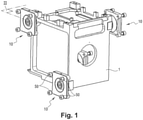
figure 1 est une vue en perspective d'un dispositif inertiel selon l'invention ; - la
figure 2 est une vue partielle de ce dispositif inertiel en coupe selon le plan II de lafigure 1 - la
figure 3 est une vue en perspective d'un plot de fixation selon une variante de réalisation. - En référence aux figures, l'unité inertielle selon l'invention comprend un cœur inertiel, non visible sur les figures, monté dans un bâti sensiblement de forme cubique. Le bâti et le cœur inertiel forme un dispositif inertiel 1.
- Le cœur inertiel est connu en lui-même et comprend des capteurs inertiels linéaires et des capteurs inertiels angulaires disposés selon les axes d'un repère de mesure. Les capteurs inertiels linéaires sont des accéléromètres par exemple pendulaires. Les capteurs angulaires sont des gyromètres ou des gyroscopes. Le cœur inertiel comprend également une unité de traitement des signaux provenant des capteurs inertiels.
- Le bâti du dispositif inertiel 1 est pourvu de plots de fixation 10 permettant la fixation du dispositif inertiel 1 à un châssis support 100.
- Chaque plot de fixation 10 comprend un premier élément formé d'une platine 20 délimitant un alésage 21 dans lequel est suspendu un deuxième élément formé d'un insert, généralement désigné en 40, relié à la platine 20 par un corps 60 en matériau élastiquement déformable.
- L'alésage 21 comprend une première extrémité orientée vers le bâti du dispositif inertiel 1 et une deuxième extrémité orientée à l'opposé, et possède un axe central sensiblement perpendiculaire à une semelle par laquelle la platine 20 prend appui contre le châssis support 100. L'alésage 21 comprend un premier tronçon cylindrique 21.1 de plus grand diamètre du côté de la première extrémité, un deuxième tronçon cylindrique 21.2 de plus petit diamètre du côté de la deuxième extrémité, et un tronçon tronconique 21.3 reliant les tronçons cylindriques 21.1, 21.2 l'un à l'autre. La platine 20 comprend des moyens de son ancrage au châssis support 100, ici sous la forme de trous permettant le passage de vis de fixation 50 engagées dans des taraudages du châssis support 100 ou de taraudages dans lesquels sont engagées des vis passant par des trous ménagés dans le châssis support 100.
- L'insert 40 a une forme de révolution avec une première face d'extrémité 41 pour prendre appui contre une surface 4 du bâti du dispositif inertiel 1 et, à l'opposé, une deuxième face d'extrémité 42. L'insert 40 comprend une portion de centrage 43 s'étendant en saillie du centre de la première face d'extrémité 41 et délimite un conduit 44 central débouchant d'une part au centre de la portion de centrage 43 et d'autre part au centre de la deuxième face d'extrémité 42. Le conduit 44 est ici étagé et comprend un tronçon principal débouchant au centre de la portion de centrage 43 et un lamage d'entrée débouchant au centre de la deuxième face d'extrémité 42. Le tronçon principal est destiné à accueillir un corps d'une vis 70 ayant une tête accueillie dans le lamage d'entrée de telle manière que le corps ait un tronçon d'extrémité fileté s'étendant en saillie de la portion de centrage 43. Le tronçon d'extrémité fileté qui s'étend en saillie de la portion de centrage 43 est engagé dans un taraudage 2 débouchant par un lamage d'entrée 3 sur la surface 4 du bâti du dispositif inertiel 1 et la tête de la vis 70 est accessible depuis la deuxième face d'extrémité 42 de l'insert 40. La portion de centrage 43 est reçue dans le lamage d'entrée 3 du taraudage 2 avec un ajustement glissant pour assurer un ajustement glissant pour assurer un centrage de l'insert 40 sur le bâti du dispositif inertiel 1 qui soit suffisant pour empêcher qu'un déplacement relatif de l'insert 40 et du bâti du dispositif inertiel 1 n'engendre des contraintes mécaniques susceptibles d'altérer les performances du dispositif inertiel 1. L'ajustement glissant est ici de préférence du type H7g6. La portion de centrage 43 ne touche pas le fond du lamage d'entrée 3 et a une longueur suffisamment faible pour assurer un centrage court.
- L'insert 40 a une longueur totale supérieure à celle de la platine 20 (longueurs mesurées parallèlement aux axes centraux de l'alésage 21 et du conduit 44).
- La surface externe de l'insert 40 est une surface de révolution qui comprend un premier tronçon cylindrique 45.1 de plus grand diamètre du côté de la première face d'extrémité 41, un deuxième tronçon cylindrique 45.2 de plus petit diamètre du côté de la deuxième face d'extrémité 42, et un tronçon tronconique 45.3 reliant les tronçons cylindriques 45.1, 45.2 l'un à l'autre.
- Le tronçon cylindrique 21.2 s'étend en regard du tronçon cylindrique 45.2, le tronçon tronconique 21.3 s'étend en regard du tronçon tronconique 45.3 et le tronçon cylindrique 21.1 s'étend en regard du tronçon tronconique 45.3. Le premier tronçon cylindrique 45.1 et la partie adjacente du tronçon tronconique 45.3 s'étendent au-delà de la première extrémité de l'alésage 21 en saillie de la platine 40. Les tronçons cylindriques 21.1, 21.2 ont des diamètres très supérieurs, de plusieurs millimètres, aux tronçons cylindriques 45.1, 45.2.
- Le tronçon tronconique 21.3 est ainsi orienté vers le bâti du dispositif inertiel 1 et a le même angle que le tronçon tronconique 45.3 qui est orienté vers le tronçon tronconique 21.3 de l'alésage 21.
- Le corps 60 est ici en matériau élastomère et est agencé pour rappeler élastiquement l'insert 40, d'une part latéralement, dans une position coaxiale par rapport à l'alésage 21 et, d'autre part longitudinalement, dans une position en saillie de la platine 20 vers le bâti du dispositif inertiel 1. Le corps 60 a, à cette fin, une forme annulaire avec une surface externe épousant et recouvrant totalement la surface de l'alésage 21 et une surface interne épousant et recouvrant totalement la surface externe de l'insert 40. Le corps 60, qui est d'une seule pièce, a ainsi : une première portion annulaire qui s'étend entre le tronçon tronconique 45.3 d'une part et le tronçon tronconique 21.3 et le premier tronçon cylindrique 21.1 d'autre part ; et une deuxième portion annulaire qui s'étend entre les deuxièmes tronçons cylindriques 45.2, 21.2. La deuxième portion annulaire comprend une surface d'extrémité concave à concavité orientée comme la deuxième face d'extrémité 42. La surface d'extrémité concave présente ici une gorge plane ayant une section transversale sensiblement en forme de U.
- De préférence, le corps 60 est surmoulé sur la platine 20 et l'insert 40 de sorte que sa surface externe est solidaire, par adhésion, de la paroi de l'alésage 21 de la platine 20 et sa surface interne est solidaire, par adhésion, de la surface extérieure de l'insert 40.
- En variante, comme représenté sur la
figure 3 , la portion de centrage et le logement sont disposés au niveau du contact entre les surfaces d'appui du châssis support 100 et de la platine 20. - Plus précisément, la platine 20 a une surface d'appui 25 contre le châssis support 100. Une portion de centrage 26, sous la forme d'une couronne annulaire, s'étend en saillie de la surface d'appui 25 coaxialement à l'alésage 21.
- Le châssis support 100 comprend alors, sur sa surface d'appui en contact avec la surface d'appui 25, un renfoncement agencé pour accueillir la portion de centrage 26. Le renfoncement a par exemple la forme d'un alésage recevant la portion de centrage 25 avec un jeu de 50 µm maximum.
- En variante, la portion de centrage 26 peut s'étendre en saillie de la surface d'appui du châssis support 100 et le logement destiné à accueillir ladite portion de centrage peut être ménagé dans la platine 20.
- L'ajustement de la portion de centrage 26 du châssis support dans le logement de la platine peut être serré ou glissant jusqu'à un ajustement autorisant un jeu de 50 µm.
- Bien entendu, l'invention n'est pas limitée aux modes de réalisation décrits mais englobe toute variante entrant dans le champ de l'invention telle que définie par les revendications.
- En particulier, l'insert peut avoir une autre forme et en particulier une autre forme extérieure de même que l'alésage peut avoir une autre forme.
- Le corps 60 peut avoir d'autres formes que celle décrite et par exemple il peut ne pas recouvrir en totalité la paroi de l'alésage et/ou la surface externe de l'insert.
- Le corps 60 peut être formé de plusieurs pièces, par exemple plusieurs segments angulaires séparés.
- Les vis peuvent être vissées dans la platine et/ou dans l'insert.
- Le diamètre du premier tronçon cylindrique 45.1 peut être inférieur à celui du deuxième tronçon cylindrique 21.2.
- La portion de centrage peut être formée par le premier tronçon cylindrique 45.1.
- La portion de centrage 43 peut s'étendre en saillie de la surface d'appui du dispositif inertiel 1 et le logement destiné à accueillir ladite portion de centrage peut être ménagé dans l'insert 40.
- L'ajustement de la portion de centrage 43 dans le logement 3 peut être serré ou glissant jusqu'à un ajustement autorisant un jeu de 50 µm.
- La portion de centrage 43 peut être désaxée par rapport au conduit 44.
Claims (13)
- Unité comprenant un dispositif inertiel de détection (1) pourvu de plots de fixation (10) permettant la fixation du dispositif inertiel à un châssis support (100), au moins un des plots de fixation (10) comprenant deux éléments qui sont fixés pour l'un au châssis support en ayant une surface d'appui au contact d'une surface d'appui du châssis support et pour l'autre au dispositif inertiel en ayant une surface d'appui au contact d'une surface d'appui du dispositif inertiel et qui sont suspendus l'un par rapport à l'autre au moyen d'un corps en matériau élastiquement déformable, au moins l'un des éléments étant fixé par au moins une vis et caractérisée en ce que les surfaces d'appui correspondantes étant respectivement pourvues d'une portion de centrage (43) et d'un logement (3) recevant ladite portion de centrage avec un ajustement permettant un jeu d'au plus 50µm.
- Unité selon la revendication 1, dans laquelle l'un des éléments est une platine (20) ayant des moyens de son ancrage au châssis support et délimitant un alésage (21), et l'autre des éléments est un insert (40) maintenu suspendu dans l'alésage par le corps en matériau élastiquement déformable (60), l'insert (40) ayant une première face d'extrémité (41) qui forme la surface d'appui en contact avec la surface d'appui du dispositif inertiel (1) et délimitant un conduit (44) recevant une vis (70) ayant un tronçon fileté qui s'étend en saillie de la première face d'extrémité pour être engagé dans un taraudage (2) du dispositif inertiel (1).
- Unité selon la revendication 2, dans laquelle la portion de centrage (43) s'étend en saillie de la première face d'extrémité (41).
- Unité selon la revendication 2 ou la revendication 3, dans laquelle la portion de centrage (43) est coaxiale au conduit (44).
- Unité selon l'une quelconque des revendications 2 à 4, dans laquelle la platine (20) possède une semelle pour être en appui contre le châssis support (100).
- Unité selon l'une quelconque des revendications 2 à 5, dans laquelle l'alésage (21) comprend un tronçon tronconique (21.3) orienté vers le dispositif inertiel (1) et l'insert (40) comprend un tronçon de surface externe tronconique (45.3) orientée vers le tronçon tronconique (21.3) de l'alésage (21), une portion annulaire du corps en matériau élastiquement déformable (60) s'étendant entre le tronçon tronconique (21.3) de l'alésage (21) et le tronçon de surface externe tronconique (45.3) de l'insert (40).
- Unité selon la revendication 6, dans laquelle l'insert (40) comprend du côté de la deuxième face d'extrémité (42) un tronçon de surface externe cylindrique (45.2) en regard d'un tronçon cylindrique (21.2) de l'alésage (21), le corps en matériau élastiquement déformable (60) comprenant entre le tronçon de surface externe cylindrique (45.2) de l'insert (40) et le tronçon cylindrique (21.2) de l'alésage (21) une partie annulaire concave à concavité orientée comme la deuxième face d'extrémité (42).
- Unité selon la revendication 7, dans laquelle l'insert (40) comprend du côté de la première face d'extrémité (41) un tronçon de surface externe cylindrique (45.1) s'étendant en saillie de la platine (20).
- Unité selon l'une quelconque des revendications 2 à 8, dans laquelle le corps en matériau élastiquement déformable (60) a une forme annulaire avec une surface externe solidaire de l'alésage (21) de la platine (20) et une surface interne solidaire d'une surface extérieure de l'insert (40).
- Unité selon l'une quelconque des revendications 2 à 9, dans laquelle la portion de centrage (43) s'étend en saillie de la surface d'appui du dispositif inertiel et le logement est ménagé dans l'insert (40).
- Unité selon la revendication 1 ou la revendication 2, dans laquelle la portion de centrage et le logement sont disposés au niveau du contact entre les surfaces d'appui du châssis support et de l'élément correspondant.
- Unité selon l'une quelconque des revendications précédentes, dans laquelle l'ajustement glissant est H7g6.
- Unité selon l'une quelconque des revendications précédentes, dans laquelle la portion de centrage est agencée pour assurer un centrage court.
Applications Claiming Priority (2)
| Application Number | Priority Date | Filing Date | Title |
|---|---|---|---|
| FR1762016A FR3074894B1 (fr) | 2017-12-12 | 2017-12-12 | Unite inertielle amelioree a dispositif inertiel suspendu |
| PCT/EP2018/083848 WO2019115359A1 (fr) | 2017-12-12 | 2018-12-06 | Unité inertielle améliorée à dispositif inertiel suspendu |
Publications (2)
| Publication Number | Publication Date |
|---|---|
| EP3724604A1 EP3724604A1 (fr) | 2020-10-21 |
| EP3724604B1 true EP3724604B1 (fr) | 2022-01-26 |
Family
ID=61873429
Family Applications (1)
| Application Number | Title | Priority Date | Filing Date |
|---|---|---|---|
| EP18811312.0A Active EP3724604B1 (fr) | 2017-12-12 | 2018-12-06 | Unité inertielle améliorée à dispositif inertiel suspendu |
Country Status (7)
| Country | Link |
|---|---|
| US (1) | US10948298B2 (fr) |
| EP (1) | EP3724604B1 (fr) |
| CN (1) | CN111542729B (fr) |
| FR (1) | FR3074894B1 (fr) |
| IL (1) | IL275245B (fr) |
| RU (1) | RU2747441C1 (fr) |
| WO (1) | WO2019115359A1 (fr) |
Families Citing this family (1)
| Publication number | Priority date | Publication date | Assignee | Title |
|---|---|---|---|---|
| RU2752433C1 (ru) * | 2020-04-17 | 2021-07-28 | Китайский Университет Горного Дела И Технологии | Система глушения вибраций для интегрированного устройства позиционирования с инерциальной навигацией, содержащегося в проходческом комбайне, и способ ее применения |
Family Cites Families (14)
| Publication number | Priority date | Publication date | Assignee | Title |
|---|---|---|---|---|
| FR809065A (fr) * | 1935-11-13 | 1937-02-23 | Dispositif de liaison servant d'amortisseur de vibrations et de chocs | |
| US2919882A (en) * | 1955-06-06 | 1960-01-05 | United Aircraft Corp | Vibration-resistant mounting |
| US5348267A (en) * | 1992-09-18 | 1994-09-20 | Eaton Corporation | Apparatus for isolating a sensor |
| US5366200A (en) * | 1992-09-29 | 1994-11-22 | Scura John E | Shock mount assembly |
| US5360236A (en) * | 1992-12-14 | 1994-11-01 | Honeywell Inc. | Apparatus and methods for mounting an inertial sensor chassis to an aircraft support frame |
| US5927680A (en) * | 1997-07-01 | 1999-07-27 | Mcdonnell Douglas Corporation | Rate gyro isolation assembly |
| US6371073B1 (en) * | 2000-11-02 | 2002-04-16 | Caterpillar Inc. | Isolated cover with independent sealing system |
| US6578682B2 (en) * | 2001-04-26 | 2003-06-17 | Honeywell International Inc. | Compact vibration isolation system for an inertial sensor assembly |
| US20040150144A1 (en) * | 2003-01-30 | 2004-08-05 | Honeywell International Inc. | Elastomeric vibration and shock isolation for inertial sensor assemblies |
| US8061695B2 (en) * | 2007-06-06 | 2011-11-22 | Honeywell International Inc. | Adjustable mounting vibration isolator |
| CN102121829B (zh) * | 2010-08-09 | 2013-06-12 | 汪滔 | 一种微型惯性测量系统 |
| RU121364U1 (ru) * | 2011-12-16 | 2012-10-20 | Открытое акционерное общество "Государственный научно-исследовательский институт приборостроения" | Амортизированный блок датчиков первичной информации бесплатформенных инерциальных навигационных систем |
| FR3039641B1 (fr) * | 2015-07-31 | 2017-08-11 | Sagem Defense Securite | Dispositif de mesure inertielle a double suspension |
| JP6551200B2 (ja) * | 2015-12-02 | 2019-07-31 | スズキ株式会社 | 車両用内燃機関の支持装置 |
-
2017
- 2017-12-12 FR FR1762016A patent/FR3074894B1/fr active Active
-
2018
- 2018-12-06 RU RU2020122906A patent/RU2747441C1/ru active
- 2018-12-06 US US16/771,183 patent/US10948298B2/en active Active
- 2018-12-06 EP EP18811312.0A patent/EP3724604B1/fr active Active
- 2018-12-06 WO PCT/EP2018/083848 patent/WO2019115359A1/fr not_active Ceased
- 2018-12-06 CN CN201880080630.0A patent/CN111542729B/zh active Active
-
2020
- 2020-06-09 IL IL275245A patent/IL275245B/en unknown
Also Published As
| Publication number | Publication date |
|---|---|
| US20200300632A1 (en) | 2020-09-24 |
| RU2747441C1 (ru) | 2021-05-05 |
| CN111542729A (zh) | 2020-08-14 |
| US10948298B2 (en) | 2021-03-16 |
| IL275245A (en) | 2020-07-30 |
| FR3074894B1 (fr) | 2020-01-03 |
| CN111542729B (zh) | 2021-08-24 |
| WO2019115359A1 (fr) | 2019-06-20 |
| IL275245B (en) | 2021-09-30 |
| EP3724604A1 (fr) | 2020-10-21 |
| FR3074894A1 (fr) | 2019-06-14 |
Similar Documents
| Publication | Publication Date | Title |
|---|---|---|
| EP3357811B1 (fr) | Atterrisseur d`aeronef | |
| FR2886402A1 (fr) | Collier de mesure de la deformation laterale d'une eprouvette lors d'essais de compression, notamment uniaxiale ou triaxiale | |
| EP3724604B1 (fr) | Unité inertielle améliorée à dispositif inertiel suspendu | |
| EP2686637B1 (fr) | Capteur inductif de proximite et procede de montage dudit capteur | |
| FR2966503A1 (fr) | Montage de capteur pour moteur a turbine | |
| FR2966500A1 (fr) | Systeme de communication pour moteur a turbine | |
| FR2973292A1 (fr) | Train de vehicule comportant un palier et palier correspondant | |
| EP2384970B1 (fr) | Système de commande d'organe de vol, dispositif de commande de vol incluant un tel système, et utilisation d'un tel système | |
| EP4452674A1 (fr) | Organe electronique et dispositif de retenue elastique | |
| EP2812214B1 (fr) | Element de fixation d'un organe fonctionnel pour vehicule automobile | |
| EP3308121B1 (fr) | Dispositif de détection de pression à découplage mécanique | |
| EP3358308B1 (fr) | Cible de mesure magnetique | |
| WO2023041866A1 (fr) | Systeme d'accouplement en rotation sans jeu entre deux arbres | |
| FR3133231A1 (fr) | Instrument de mesure configuré pour déterminer des coordonnées d’un point d’intérêt | |
| FR2942538A1 (fr) | Dispositif de mesure de moment de charniere | |
| EP3142873B1 (fr) | Systeme d 'antiblocage des roues d'un vehicule | |
| WO2025190879A1 (fr) | Systeme de fixation permettant de maintenir un dispositif embarque sur un velo de course | |
| WO1995001556A1 (fr) | Capteur de force a deux voies et application notamment a la mesure d'un torseur de forces | |
| EP0068920B1 (fr) | Débitmètre à tourbillon, notamment pour fluides à faible viscosité | |
| FR3159591A1 (fr) | Attache instrumentee de moteur d’aeronef et aeronef comprenant une telle attache. | |
| EP4707817A2 (fr) | Unité de mesure inertielle à sensibilité réduite aux contraintes thermomécaniques | |
| FR3013447A1 (fr) | Dispositif de mesure de niveau de liquide | |
| FR3136056A3 (fr) | Anneau à aimant et enregistreur chronologique de bruit et/ou de fréquence. | |
| FR3164955A1 (fr) | Support pour capteur radar | |
| FR2996890A1 (fr) | Ensemble de support d'un element orientable, et equipement optique incorporant un tel ensemble |
Legal Events
| Date | Code | Title | Description |
|---|---|---|---|
| STAA | Information on the status of an ep patent application or granted ep patent |
Free format text: STATUS: UNKNOWN |
|
| STAA | Information on the status of an ep patent application or granted ep patent |
Free format text: STATUS: THE INTERNATIONAL PUBLICATION HAS BEEN MADE |
|
| PUAI | Public reference made under article 153(3) epc to a published international application that has entered the european phase |
Free format text: ORIGINAL CODE: 0009012 |
|
| STAA | Information on the status of an ep patent application or granted ep patent |
Free format text: STATUS: REQUEST FOR EXAMINATION WAS MADE |
|
| 17P | Request for examination filed |
Effective date: 20200605 |
|
| AK | Designated contracting states |
Kind code of ref document: A1 Designated state(s): AL AT BE BG CH CY CZ DE DK EE ES FI FR GB GR HR HU IE IS IT LI LT LU LV MC MK MT NL NO PL PT RO RS SE SI SK SM TR |
|
| AX | Request for extension of the european patent |
Extension state: BA ME |
|
| DAV | Request for validation of the european patent (deleted) | ||
| DAX | Request for extension of the european patent (deleted) | ||
| GRAP | Despatch of communication of intention to grant a patent |
Free format text: ORIGINAL CODE: EPIDOSNIGR1 |
|
| STAA | Information on the status of an ep patent application or granted ep patent |
Free format text: STATUS: GRANT OF PATENT IS INTENDED |
|
| RIC1 | Information provided on ipc code assigned before grant |
Ipc: G01C 21/16 20060101AFI20210701BHEP Ipc: F16F 15/02 20060101ALI20210701BHEP Ipc: F16F 1/38 20060101ALI20210701BHEP Ipc: F16F 15/08 20060101ALI20210701BHEP |
|
| INTG | Intention to grant announced |
Effective date: 20210728 |
|
| GRAS | Grant fee paid |
Free format text: ORIGINAL CODE: EPIDOSNIGR3 |
|
| GRAA | (expected) grant |
Free format text: ORIGINAL CODE: 0009210 |
|
| STAA | Information on the status of an ep patent application or granted ep patent |
Free format text: STATUS: THE PATENT HAS BEEN GRANTED |
|
| RAP3 | Party data changed (applicant data changed or rights of an application transferred) |
Owner name: SAFRAN ELECTRONICS & DEFENSE |
|
| RIN1 | Information on inventor provided before grant (corrected) |
Inventor name: GIORGIO, ALAIN |
|
| AK | Designated contracting states |
Kind code of ref document: B1 Designated state(s): AL AT BE BG CH CY CZ DE DK EE ES FI FR GB GR HR HU IE IS IT LI LT LU LV MC MK MT NL NO PL PT RO RS SE SI SK SM TR |
|
| REG | Reference to a national code |
Ref country code: GB Ref legal event code: FG4D Free format text: NOT ENGLISH |
|
| REG | Reference to a national code |
Ref country code: CH Ref legal event code: EP |
|
| REG | Reference to a national code |
Ref country code: AT Ref legal event code: REF Ref document number: 1465614 Country of ref document: AT Kind code of ref document: T Effective date: 20220215 |
|
| REG | Reference to a national code |
Ref country code: IE Ref legal event code: FG4D Free format text: LANGUAGE OF EP DOCUMENT: FRENCH |
|
| REG | Reference to a national code |
Ref country code: DE Ref legal event code: R096 Ref document number: 602018030175 Country of ref document: DE |
|
| REG | Reference to a national code |
Ref country code: SE Ref legal event code: TRGR |
|
| REG | Reference to a national code |
Ref country code: LT Ref legal event code: MG9D |
|
| REG | Reference to a national code |
Ref country code: NL Ref legal event code: MP Effective date: 20220126 |
|
| REG | Reference to a national code |
Ref country code: AT Ref legal event code: MK05 Ref document number: 1465614 Country of ref document: AT Kind code of ref document: T Effective date: 20220126 |
|
| PG25 | Lapsed in a contracting state [announced via postgrant information from national office to epo] |
Ref country code: NL Free format text: LAPSE BECAUSE OF FAILURE TO SUBMIT A TRANSLATION OF THE DESCRIPTION OR TO PAY THE FEE WITHIN THE PRESCRIBED TIME-LIMIT Effective date: 20220126 |
|
| PG25 | Lapsed in a contracting state [announced via postgrant information from national office to epo] |
Ref country code: RS Free format text: LAPSE BECAUSE OF FAILURE TO SUBMIT A TRANSLATION OF THE DESCRIPTION OR TO PAY THE FEE WITHIN THE PRESCRIBED TIME-LIMIT Effective date: 20220126 Ref country code: PT Free format text: LAPSE BECAUSE OF FAILURE TO SUBMIT A TRANSLATION OF THE DESCRIPTION OR TO PAY THE FEE WITHIN THE PRESCRIBED TIME-LIMIT Effective date: 20220526 Ref country code: NO Free format text: LAPSE BECAUSE OF FAILURE TO SUBMIT A TRANSLATION OF THE DESCRIPTION OR TO PAY THE FEE WITHIN THE PRESCRIBED TIME-LIMIT Effective date: 20220426 Ref country code: LT Free format text: LAPSE BECAUSE OF FAILURE TO SUBMIT A TRANSLATION OF THE DESCRIPTION OR TO PAY THE FEE WITHIN THE PRESCRIBED TIME-LIMIT Effective date: 20220126 Ref country code: HR Free format text: LAPSE BECAUSE OF FAILURE TO SUBMIT A TRANSLATION OF THE DESCRIPTION OR TO PAY THE FEE WITHIN THE PRESCRIBED TIME-LIMIT Effective date: 20220126 Ref country code: ES Free format text: LAPSE BECAUSE OF FAILURE TO SUBMIT A TRANSLATION OF THE DESCRIPTION OR TO PAY THE FEE WITHIN THE PRESCRIBED TIME-LIMIT Effective date: 20220126 Ref country code: BG Free format text: LAPSE BECAUSE OF FAILURE TO SUBMIT A TRANSLATION OF THE DESCRIPTION OR TO PAY THE FEE WITHIN THE PRESCRIBED TIME-LIMIT Effective date: 20220426 |
|
| PG25 | Lapsed in a contracting state [announced via postgrant information from national office to epo] |
Ref country code: PL Free format text: LAPSE BECAUSE OF FAILURE TO SUBMIT A TRANSLATION OF THE DESCRIPTION OR TO PAY THE FEE WITHIN THE PRESCRIBED TIME-LIMIT Effective date: 20220126 Ref country code: LV Free format text: LAPSE BECAUSE OF FAILURE TO SUBMIT A TRANSLATION OF THE DESCRIPTION OR TO PAY THE FEE WITHIN THE PRESCRIBED TIME-LIMIT Effective date: 20220126 Ref country code: GR Free format text: LAPSE BECAUSE OF FAILURE TO SUBMIT A TRANSLATION OF THE DESCRIPTION OR TO PAY THE FEE WITHIN THE PRESCRIBED TIME-LIMIT Effective date: 20220427 Ref country code: FI Free format text: LAPSE BECAUSE OF FAILURE TO SUBMIT A TRANSLATION OF THE DESCRIPTION OR TO PAY THE FEE WITHIN THE PRESCRIBED TIME-LIMIT Effective date: 20220126 Ref country code: AT Free format text: LAPSE BECAUSE OF FAILURE TO SUBMIT A TRANSLATION OF THE DESCRIPTION OR TO PAY THE FEE WITHIN THE PRESCRIBED TIME-LIMIT Effective date: 20220126 |
|
| PG25 | Lapsed in a contracting state [announced via postgrant information from national office to epo] |
Ref country code: IS Free format text: LAPSE BECAUSE OF FAILURE TO SUBMIT A TRANSLATION OF THE DESCRIPTION OR TO PAY THE FEE WITHIN THE PRESCRIBED TIME-LIMIT Effective date: 20220526 |
|
| REG | Reference to a national code |
Ref country code: DE Ref legal event code: R097 Ref document number: 602018030175 Country of ref document: DE |
|
| PG25 | Lapsed in a contracting state [announced via postgrant information from national office to epo] |
Ref country code: SM Free format text: LAPSE BECAUSE OF FAILURE TO SUBMIT A TRANSLATION OF THE DESCRIPTION OR TO PAY THE FEE WITHIN THE PRESCRIBED TIME-LIMIT Effective date: 20220126 Ref country code: SK Free format text: LAPSE BECAUSE OF FAILURE TO SUBMIT A TRANSLATION OF THE DESCRIPTION OR TO PAY THE FEE WITHIN THE PRESCRIBED TIME-LIMIT Effective date: 20220126 Ref country code: RO Free format text: LAPSE BECAUSE OF FAILURE TO SUBMIT A TRANSLATION OF THE DESCRIPTION OR TO PAY THE FEE WITHIN THE PRESCRIBED TIME-LIMIT Effective date: 20220126 Ref country code: EE Free format text: LAPSE BECAUSE OF FAILURE TO SUBMIT A TRANSLATION OF THE DESCRIPTION OR TO PAY THE FEE WITHIN THE PRESCRIBED TIME-LIMIT Effective date: 20220126 Ref country code: DK Free format text: LAPSE BECAUSE OF FAILURE TO SUBMIT A TRANSLATION OF THE DESCRIPTION OR TO PAY THE FEE WITHIN THE PRESCRIBED TIME-LIMIT Effective date: 20220126 Ref country code: CZ Free format text: LAPSE BECAUSE OF FAILURE TO SUBMIT A TRANSLATION OF THE DESCRIPTION OR TO PAY THE FEE WITHIN THE PRESCRIBED TIME-LIMIT Effective date: 20220126 |
|
| PG25 | Lapsed in a contracting state [announced via postgrant information from national office to epo] |
Ref country code: AL Free format text: LAPSE BECAUSE OF FAILURE TO SUBMIT A TRANSLATION OF THE DESCRIPTION OR TO PAY THE FEE WITHIN THE PRESCRIBED TIME-LIMIT Effective date: 20220126 |
|
| PLBE | No opposition filed within time limit |
Free format text: ORIGINAL CODE: 0009261 |
|
| STAA | Information on the status of an ep patent application or granted ep patent |
Free format text: STATUS: NO OPPOSITION FILED WITHIN TIME LIMIT |
|
| 26N | No opposition filed |
Effective date: 20221027 |
|
| PG25 | Lapsed in a contracting state [announced via postgrant information from national office to epo] |
Ref country code: SI Free format text: LAPSE BECAUSE OF FAILURE TO SUBMIT A TRANSLATION OF THE DESCRIPTION OR TO PAY THE FEE WITHIN THE PRESCRIBED TIME-LIMIT Effective date: 20220126 |
|
| PG25 | Lapsed in a contracting state [announced via postgrant information from national office to epo] |
Ref country code: IT Free format text: LAPSE BECAUSE OF FAILURE TO SUBMIT A TRANSLATION OF THE DESCRIPTION OR TO PAY THE FEE WITHIN THE PRESCRIBED TIME-LIMIT Effective date: 20220126 |
|
| REG | Reference to a national code |
Ref country code: CH Ref legal event code: PL |
|
| REG | Reference to a national code |
Ref country code: BE Ref legal event code: MM Effective date: 20221231 |
|
| PG25 | Lapsed in a contracting state [announced via postgrant information from national office to epo] |
Ref country code: LU Free format text: LAPSE BECAUSE OF NON-PAYMENT OF DUE FEES Effective date: 20221206 |
|
| PG25 | Lapsed in a contracting state [announced via postgrant information from national office to epo] |
Ref country code: LI Free format text: LAPSE BECAUSE OF NON-PAYMENT OF DUE FEES Effective date: 20221231 Ref country code: IE Free format text: LAPSE BECAUSE OF NON-PAYMENT OF DUE FEES Effective date: 20221206 Ref country code: CH Free format text: LAPSE BECAUSE OF NON-PAYMENT OF DUE FEES Effective date: 20221231 |
|
| PG25 | Lapsed in a contracting state [announced via postgrant information from national office to epo] |
Ref country code: BE Free format text: LAPSE BECAUSE OF NON-PAYMENT OF DUE FEES Effective date: 20221231 |
|
| PG25 | Lapsed in a contracting state [announced via postgrant information from national office to epo] |
Ref country code: CY Free format text: LAPSE BECAUSE OF FAILURE TO SUBMIT A TRANSLATION OF THE DESCRIPTION OR TO PAY THE FEE WITHIN THE PRESCRIBED TIME-LIMIT Effective date: 20220126 |
|
| PG25 | Lapsed in a contracting state [announced via postgrant information from national office to epo] |
Ref country code: MK Free format text: LAPSE BECAUSE OF FAILURE TO SUBMIT A TRANSLATION OF THE DESCRIPTION OR TO PAY THE FEE WITHIN THE PRESCRIBED TIME-LIMIT Effective date: 20220126 Ref country code: HU Free format text: LAPSE BECAUSE OF FAILURE TO SUBMIT A TRANSLATION OF THE DESCRIPTION OR TO PAY THE FEE WITHIN THE PRESCRIBED TIME-LIMIT; INVALID AB INITIO Effective date: 20181206 |
|
| PG25 | Lapsed in a contracting state [announced via postgrant information from national office to epo] |
Ref country code: MC Free format text: LAPSE BECAUSE OF FAILURE TO SUBMIT A TRANSLATION OF THE DESCRIPTION OR TO PAY THE FEE WITHIN THE PRESCRIBED TIME-LIMIT Effective date: 20220126 |
|
| PG25 | Lapsed in a contracting state [announced via postgrant information from national office to epo] |
Ref country code: MC Free format text: LAPSE BECAUSE OF FAILURE TO SUBMIT A TRANSLATION OF THE DESCRIPTION OR TO PAY THE FEE WITHIN THE PRESCRIBED TIME-LIMIT Effective date: 20220126 |
|
| PG25 | Lapsed in a contracting state [announced via postgrant information from national office to epo] |
Ref country code: MT Free format text: LAPSE BECAUSE OF FAILURE TO SUBMIT A TRANSLATION OF THE DESCRIPTION OR TO PAY THE FEE WITHIN THE PRESCRIBED TIME-LIMIT Effective date: 20220126 |
|
| PG25 | Lapsed in a contracting state [announced via postgrant information from national office to epo] |
Ref country code: TR Free format text: LAPSE BECAUSE OF FAILURE TO SUBMIT A TRANSLATION OF THE DESCRIPTION OR TO PAY THE FEE WITHIN THE PRESCRIBED TIME-LIMIT Effective date: 20220126 |
|
| PGFP | Annual fee paid to national office [announced via postgrant information from national office to epo] |
Ref country code: GB Payment date: 20251229 Year of fee payment: 8 |
|
| PGFP | Annual fee paid to national office [announced via postgrant information from national office to epo] |
Ref country code: FR Payment date: 20251222 Year of fee payment: 8 |
|
| PGFP | Annual fee paid to national office [announced via postgrant information from national office to epo] |
Ref country code: SE Payment date: 20251217 Year of fee payment: 8 |
|
| PGFP | Annual fee paid to national office [announced via postgrant information from national office to epo] |
Ref country code: DE Payment date: 20251222 Year of fee payment: 8 |