EP3723552B1 - Stuhl - Google Patents
Stuhl Download PDFInfo
- Publication number
- EP3723552B1 EP3723552B1 EP18887789.8A EP18887789A EP3723552B1 EP 3723552 B1 EP3723552 B1 EP 3723552B1 EP 18887789 A EP18887789 A EP 18887789A EP 3723552 B1 EP3723552 B1 EP 3723552B1
- Authority
- EP
- European Patent Office
- Prior art keywords
- cross
- seat panel
- section
- parts
- sections
- Prior art date
- Legal status (The legal status is an assumption and is not a legal conclusion. Google has not performed a legal analysis and makes no representation as to the accuracy of the status listed.)
- Active
Links
Images


Classifications
-
- A—HUMAN NECESSITIES
- A47—FURNITURE; DOMESTIC ARTICLES OR APPLIANCES; COFFEE MILLS; SPICE MILLS; SUCTION CLEANERS IN GENERAL
- A47C—CHAIRS; SOFAS; BEDS
- A47C4/00—Foldable, collapsible or dismountable chairs
- A47C4/02—Dismountable chairs
- A47C4/03—Non-upholstered chairs, e.g. metal, plastic or wooden chairs
-
- A—HUMAN NECESSITIES
- A47—FURNITURE; DOMESTIC ARTICLES OR APPLIANCES; COFFEE MILLS; SPICE MILLS; SUCTION CLEANERS IN GENERAL
- A47C—CHAIRS; SOFAS; BEDS
- A47C4/00—Foldable, collapsible or dismountable chairs
- A47C4/02—Dismountable chairs
- A47C4/021—Dismountable chairs connected by slotted joints
-
- F—MECHANICAL ENGINEERING; LIGHTING; HEATING; WEAPONS; BLASTING
- F16—ENGINEERING ELEMENTS AND UNITS; GENERAL MEASURES FOR PRODUCING AND MAINTAINING EFFECTIVE FUNCTIONING OF MACHINES OR INSTALLATIONS; THERMAL INSULATION IN GENERAL
- F16B—DEVICES FOR FASTENING OR SECURING CONSTRUCTIONAL ELEMENTS OR MACHINE PARTS TOGETHER, e.g. NAILS, BOLTS, CIRCLIPS, CLAMPS, CLIPS OR WEDGES; JOINTS OR JOINTING
- F16B12/00—Jointing of furniture or the like, e.g. hidden from exterior
- F16B12/10—Jointing of furniture or the like, e.g. hidden from exterior using pegs, bolts, tenons, clamps, clips, or the like
- F16B12/12—Jointing of furniture or the like, e.g. hidden from exterior using pegs, bolts, tenons, clamps, clips, or the like for non-metal furniture parts, e.g. made of wood, of plastics
- F16B12/22—Jointing of furniture or the like, e.g. hidden from exterior using pegs, bolts, tenons, clamps, clips, or the like for non-metal furniture parts, e.g. made of wood, of plastics using keyhole-shaped slots and pins
-
- F—MECHANICAL ENGINEERING; LIGHTING; HEATING; WEAPONS; BLASTING
- F16—ENGINEERING ELEMENTS AND UNITS; GENERAL MEASURES FOR PRODUCING AND MAINTAINING EFFECTIVE FUNCTIONING OF MACHINES OR INSTALLATIONS; THERMAL INSULATION IN GENERAL
- F16B—DEVICES FOR FASTENING OR SECURING CONSTRUCTIONAL ELEMENTS OR MACHINE PARTS TOGETHER, e.g. NAILS, BOLTS, CIRCLIPS, CLAMPS, CLIPS OR WEDGES; JOINTS OR JOINTING
- F16B12/00—Jointing of furniture or the like, e.g. hidden from exterior
- F16B12/10—Jointing of furniture or the like, e.g. hidden from exterior using pegs, bolts, tenons, clamps, clips, or the like
- F16B12/12—Jointing of furniture or the like, e.g. hidden from exterior using pegs, bolts, tenons, clamps, clips, or the like for non-metal furniture parts, e.g. made of wood, of plastics
- F16B12/24—Jointing of furniture or the like, e.g. hidden from exterior using pegs, bolts, tenons, clamps, clips, or the like for non-metal furniture parts, e.g. made of wood, of plastics using separate pins, dowels, or the like
-
- F—MECHANICAL ENGINEERING; LIGHTING; HEATING; WEAPONS; BLASTING
- F16—ENGINEERING ELEMENTS AND UNITS; GENERAL MEASURES FOR PRODUCING AND MAINTAINING EFFECTIVE FUNCTIONING OF MACHINES OR INSTALLATIONS; THERMAL INSULATION IN GENERAL
- F16B—DEVICES FOR FASTENING OR SECURING CONSTRUCTIONAL ELEMENTS OR MACHINE PARTS TOGETHER, e.g. NAILS, BOLTS, CIRCLIPS, CLAMPS, CLIPS OR WEDGES; JOINTS OR JOINTING
- F16B12/00—Jointing of furniture or the like, e.g. hidden from exterior
- F16B12/10—Jointing of furniture or the like, e.g. hidden from exterior using pegs, bolts, tenons, clamps, clips, or the like
- F16B12/12—Jointing of furniture or the like, e.g. hidden from exterior using pegs, bolts, tenons, clamps, clips, or the like for non-metal furniture parts, e.g. made of wood, of plastics
- F16B12/26—Jointing of furniture or the like, e.g. hidden from exterior using pegs, bolts, tenons, clamps, clips, or the like for non-metal furniture parts, e.g. made of wood, of plastics using snap-action elements
Definitions
- the invention relates to a chair comprising a first and a second section mutually displaced from each other to form a gap there between, and a first cross-member which is configured to connect with its first free end to the first section and with its second free end to the second section, thereby bridging the gap.
- AU 63768 65 A discloses a known chair with joint arrangements.
- One object of the present invention is to provide a chair with joint arrangements for the parts which allows an easy assembling without the use of any tools or any mechanical fastening means.
- the joint arrangements should be practical to use and yet give a secure assembly of the furniture.
- the assembled chair should provide a high degree of robustness that can withstand the often very high forces that a chair may be subjected to.
- the first and second sections may by way of example be the side sections of a chair, where each section comprises a front leg and a rear leg. It is also to be understood that the first and the second sections by using the same principle may form front and rear portions of a chair where the front portion comprises two front legs and the rear portion comprising two rear legs.
- the respective section may be a pre-assembled unit where the section in addition to the legs also comprises one of the two columns configured to form a support for a back-rest of the chair.
- first and second joint arrangements being made of male parts and female parts, configured to be arranged into an interlocking arrangement by a relative movement, no tools are required to assemble the chair. Also, the assembling may be made without the requirement of any substantial body strength. Also, the chair can be easy disassembled if required.
- the dowels are preferably made by a solid material with a uniform cross-section.
- the term "uniform cross-section" should in the context of the invention be understood as a cross-section without any flexible zones, such as grooves having an extension in parallel with the longitudinal extension of the dowel.
- the uniform cross-section prevents undue flexibility of the dowel, thereby contributing to the robustness of the joint arrangement.
- the dowels are preferably made by wood.
- Each of the first and the second joint arrangements comprises two male parts and two female parts. The provision of at least two of each type prevents the first cross-member from rotation in its mounted condition. Also, it reduces the risk of splitting the material in the first and second sections. This is especially the case if these sections are made of wood.
- rims and grooves allows an easy and speedy mounting which permits interlocked parts to be moved along a first direction while at the same time preventing the parts from being moved apart in second direction transverse the first direction.
- the number of rims may vary depending on expected loads on the chair. Also, the number of rims and their design may be used as an indicator to the operator of how to orient the parts during assembly.
- the male parts of the first and second joint arrangements may be arranged in the first and the second free ends of the first cross-member, and the female parts of the first and the second joint arrangements may be arranged in the first and second sections of the chair.
- the first and second sections and the first cross-member may be arranged side by side in a flat package without any male parts projecting away from the major surface of such package.
- One female part of the first and second joint arrangements respectively may be formed by a recess formed in the first surface of the first and second sections of the chair, and said recess may have an insertion portion and a locking portion; and one female part of the first and second joint arrangements respectively may be formed by a recess having a mouth formed in a second surface of the first and second sections of the chair, and the first and second surfaces may form an angle to each other.
- the first cross-member may be mounted to the first and second sections by a substantially linear movement in view of the respective section.
- any such seat panel will close-off the mouth and not only visually hide the same, but also efficiently prevent displacement of the first cross-member.
- the thus formed chair will receive a very rigid form.
- the chair comprises a second cross-member having first and second opposing free ends, the second cross-member being configured to connect with its first free end to the first section and with its second free end to the second section thereby bridging the gap; and a third joint arrangement configured to attach the first free end of the second cross-member to the first section and a fourth joint arrangement configured to attach the second free end of the second cross-member to the second section, wherein each of the third and fourth joint arrangements comprises: at least one male part being arranged on either a free end of the second cross-member or on the respective section; and at least one female part being arranged on the other one of the respective section and the second cross-member, wherein the at least one male part is formed by a dowel extending in a longitudinal direction and having a free end facing away from a surface of the free end of the second cross-member or a first surface of the respective section, said dowel comprising a locking means in the form of at least one rim extending radially from the envelope surface of the dowel; and wherein the at
- Each of the third and fourth joint arrangements comprises two or more male parts and two or more female parts.
- the number of male parts should correspond to the number of female parts.
- the second cross-member will together with the first and second sections and the first cross-member form a closed frame and thereby provide a structurally strong frame.
- the second cross-member may be arranged across the rear end of the chair just above the rear pair of legs.
- the first and second cross-members may form a support for a seat panel making up the seat of the chair.
- the dowels are preferably made by a solid material with a uniform cross-section.
- the uniform cross-section prevents undue flexibility of the dowel, thereby contributing to the robustness of the joint arrangement.
- the dowels are preferably made by wood.
- the female parts of the third and fourth joint arrangements may be formed by recesses, each recess having an insertion portion and a locking portion.
- the male parts of the third and fourth joint arrangements may be arranged in the first and in the second free ends of the second cross-member, and the female parts of the third and the fourth joint arrangements may be arranged in the first and in the second sections of the chair.
- the female parts may be arranged in the first surface of the respective first and second sections.
- the first surface may extend substantially orthogonally to the longitudinal extension of the cross-members.
- the first and/or the second cross-members may comprise either male parts in both free ends thereof or female parts in both free ends thereof.
- the required package volume and hence package material may thereby be reduced since the male parts will extend in the longitudinal direction of the cross-members and not add to the volume of the package. Also, assembling of the chair is facilitated since the sections may be arranged resting on a solid support during mounting of the respective cross-members.
- the first and second sections may together with the first and/or the second cross-member form a frame.
- the first and second sections of the frame may be arranged in parallel with each other.
- the distances between the longitudinal center lines of the male parts of the first and second joint arrangements and the distances between the longitudinal center lines of the male parts of the third and fourth joint arrangements respective are smaller than eight times the longitudinal extension of each male part, and more preferred smaller than six times the longitudinal extension of each male part.
- the first and second cross-members do each have a substantially smaller height than length, and by arranging the male parts as close to the ends as possible as seen in the height direction, the robustness of the frame and hence the chair may be improved.
- the chair may further comprise a seat panel configured to connect with the first section and the second section thereby bridging the gap; a seat panel joint arrangement configured to attach the seat panel to a second surface of the first and the second sections, the second surface forming an angle to the first surface of the respective section; wherein the seat panel joint arrangement comprises: at least two male parts, both being arranged either on a major surface of the seat panel or both being arranged on the first and the second sections with at least one of the male parts on each section; and at least two female parts, both being arranged on the other one of the major surface of the seat panel and the respective first and second section; wherein each of the male parts is formed by a dowel extending in a longitudinal direction and having a free end facing away from the first and second sections or from the major surface of the seat panel; wherein each of the female parts is formed by a recess in the major surface of the seat panel or in the first and second sections, the recess having an elongated extension between an insertion portion and a locking portion; whereby the
- the seat panel will add to the overall strength of the frame-like structure which is formed by the two sections and the at least one cross-member, by bridging and inter-connecting the two sections.
- the seat panel will prevent such frame from twisting.
- the seat panel may fully or partly conceal the joint arrangements and also prevent the sections and the cross-members from falling apart.
- the first and second sections may by way of example be the side sections of a chair, where each section comprises a front leg and a rear leg and also one of the columns configured to form a support for a back-rest.
- the male parts of the seat panel joint arrangement may be arranged in the first and second sections, and the female parts of the seat panel joint arrangement may be arranged in the major surface of the seat panel.
- the required package volume and hence the required package material may thereby be reduced since the male parts will extend in parallel with the major plane of such package. Also, there will be no projecting parts on the seat panel.
- each female part of the seat panel joint arrangement may have an elongated extension in a direction transverse the gap between the first and second sections.
- the seat panel may thereby be mounted by a sliding movement across the gap and bridge the same.
- each female part of the seat panel joint arrangement may be arranged in a second surface of the first and second section, the second surface forming an angle ⁇ to the first surface.
- the seat panel will thereby, when mounted, visually hide the mouth of one of the female parts forming part of the first joint arrangement.
- the seat panel will also efficiently prevent displacement of the first and/or second cross-members in view of the first and second sections. Also, it will contribute to the provision of a structural rigidity of the frame-like structure which is formed by the first and the second sections and the first and second cross-members.
- the seat panel When mounting the seat panel to the frame by pushing the seat panel rearwards towards the second cross-member into the locking position, the seat panel will due to a wedge action caused by the angle ⁇ , actively force the at least two male parts of the second cross-member towards into a locking engagement with the female parts in the first and the second sections.
- the male parts of the first, second, third and fourth joint arrangements may have a longitudinal extension extending substantially perpendicularly to the longitudinal extension of the male parts of the seat panel joint arrangements. This allows building of a structure with a substantially orthogonal wall structure.
- the seat panel joint arrangement may comprise at least three male parts and at least three female parts, and the at least three male parts and the at least three female parts respectively may be arranged to define a polygon.
- At least one male part in the seat panel joint arrangement may comprise a locking means in the form of at least one rim extending radially from the envelope surface of the male part, and wherein a recess of the corresponding female part in the seat panel joint arrangement may comprise at least one corresponding groove, whereby in said locking position, the at least one rim of the male part is configured to engage the at least one corresponding groove of the female part.
- the chair may comprise a locking means arranged in the lower surface of the seat panel, wherein the locking means, in a condition when the seat panel has been mounted to the frame, engages the frame, thereby preventing the seat panel from being displaced in view of the frame.
- the rear end of the seat panel may be configured to abut a portion of a back rest of the chair, while the locking means may be configured to abut the first cross member. The seat panel is thereby prevented from being displaced in view of the frame in the depth direction Y. Further, an overall robustness of the chair is provided for.
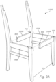
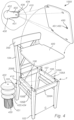
- first and second sections 100A, 100B and the first and second cross-members 200A, 200B form a frame F.
- the first and the second sections 100A, 100B and also the first and the second cross-members 200A, 200B do each have a first surface 107 and a second surface 108.
- the first surface 107 is arranged to face the interior of the frame F.
- the second surface 108 may be arranged to form a top surface configured to support the seat panel 400.
- the first and the second surfaces 107, 108 form an angle to each other, such as 90 degrees.
- the first and second sections 100A, 100B may be provided to the consumer as two pre-assembled units.
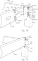
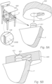
- the first and the second joint arrangements 500, 600 are identical whereby only the first joint arrangement 500 will be described in detail.
- the first joint arrangement 500 further comprises two female parts 537, 538 which are arranged in the first section 100A.
- the female parts 537, 538 are arranged in the front leg 102.
- the upper female part 538 is formed by a recess 539 having an elongated extension.
- the recess 539 has a mouth 540 which is formed in the second surface 108 of the first section 100A and which merges into a locking portion 533.
- the mouth 540 has a cross section that allows insertion of the corresponding dowel 521.
- the envelope surface of the inner wall 541 of the recess 539 comprises at least one groove 542 configured to receive the at least one rim 524 of the corresponding dowel 521 to be inserted thereto.
- the number of grooves 542 should thus correspond to the number of rims 524 on the corresponding dowel 521.
- the first cross-member 200A When mounting the first cross-member 200A to the first section 100A, see Figs. 1B-1D , the first cross-member 200A is displaced in view of the first section 100A so that the upper dowel 521 is arranged above the mouth 540 of the upper recess 538 and so that the lower dowel 521 is aligned with the insertion portion 532 of the lower recess 537.
- the first cross-member 200A is then moved relative to the first section 100A, see Fig. 1D-1E such that the dowels 521 are moved along the elongated extension of the recesses 537, 538 to the locking portions 533.
- the rims 524 of the dowels 521 see Fig.
- the beveled surface 525 of at least the upper dowel 521 will be flush with the second surfaces 108 of the first and second sections 100A, 100B, see Fig. 1E and 2B .
- the first and second sections 100A, 100B together with the first and second intermediate supports 105A, 105B form a substantially flat support surface for e.g. a seat panel 400 to be mounted thereto.
- the chair 1000 further comprises the second cross-member 200B.
- the second cross-member 200B comprises first and second opposing free ends 201B, 202B.
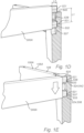
- the third and the fourth joint arrangements 700, 800 are identical whereby only the first joint arrangement will be described in detail with reference to Figs. 3A-3C .
- the third joint arrangement 700 is disclosed as comprising two male parts 720 which are arranged in the first and the second free ends 201B, 202B of the second cross-member 200B. It is also to be understood that more than two male parts 720 in each free end may be used.
- Each male part 720 may be formed as a dowel 721 which comprises a locking means 723 in the form of at least one rim 724 which extends radially from the envelope surface of the dowel 721.
- a locking means 723 in the form of at least one rim 724 which extends radially from the envelope surface of the dowel 721.
- three rims 724 are arranged one after the other as seen along the longitudinal extension of the dowel 721.
- the dowel 721 has the same cross section as that in the first and second joint arrangements 500, 600, i.e. it is provided with a beveled surface 725 having an extension in parallel with the longitudinal extension of the dowel 721. It is to be understood that other cross sections are possible, such as a circular or oval cross section.
- the dowel 721 is made by a solid material with a uniform cross-section. Also, the dowel 721 is made by wood.
- the third joint arrangement 700 further comprises two female parts 737 which are arranged in the first section 100A.
- the two female parts 737 may be identical.
- the design of the two female parts 737 may be identical with the lower female part 537 in the first joint arrangement 500.
- the number of female parts 737 should correspond to the number of male parts 720 in the third joint arrangement 300.
- more than two female parts 737 may be used in each free end may be used.
- the insertion portion 732 has a cross-section that allows the dowel 721 to be inserted by a longitudinal movement.
- the inner wall of the insertion portion 732 may be smooth.
- the insertion portion 732 merges with the locking portion 733.
- the envelope surface of the inner wall of the locking portion 733 comprises at least one groove 736 configured to receive the at least one rim 724 of the corresponding dowel 721 to be inserted thereto.
- the number of grooves 736 should thus correspond to the number of rims 724 on the corresponding dowel 721.
- the second cross-member 200B When mounting the second cross-member 200B to the first section 100A, see Fig. 3B , the second cross-member 200B is arranged in view of the first section 100A so that the dowels 721 are aligned with the insertion portions 732 of the two recesses 731. Thereafter, the second cross-member 200B is moved relative to the first section 100A such that the dowels 721 are moved along the elongated extension of the recesses 731 to the locking portions 733, see Fig 3C .
- the distance between the longitudinal center lines L1 of the male parts 521 of the first and second joint arrangements 500, 600 may be smaller than eight times the longitudinal extension L2 of each male part 521, and more preferred smaller than six times the longitudinal extension of each male part. This may also apply to the male dowels of the third and fourth joint arrangements 700, 800.
- the first and second cross-members 200A, 200B do each have a substantially smaller height than length, and by arranging the male parts as close to the ends as possible as seen in the height direction, the robustness of the frame F and hence the chair 100 may be improved.
- the frame F is suitable to support the seat panel 400 forming a seat of the chair.
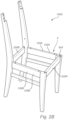
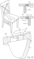
- the seat panel 400 is configured to be attached to the first and second sections 100A, 100B by a seat panel joint arrangement 410.
- the disclosed seat panel joint arrangement 410 comprises four male parts 420 and four female parts 430. Two of the male parts 420 are arranged in the second surface 108 of the first intermediate support 105A and two of the male parts 420 are arranged in the second surface 108 of the second intermediate support 105B.
- One male part 420 is positioned adjacent the front leg 102 and one mail part 420 is positioned adjacent to the rear leg 103.
- the four female parts 430 are all arranged in corresponding positions in a bottom surface of the seat panel 400.
- the seat panel joint arrangement 410 should preferably comprise at least two male parts 420, both being arranged either on a major surface of the seat panel 400 or both being arranged on the intermediate supports 105A, 105B with at least one of the male parts 420 arranged on each intermediate support 105A, 105B. It goes without saying that more than four male parts 420 and more than four female parts 430 may be used. It is to be understood that the male parts 420, with remained function may be arranged in the first and the second sections 100A, 100B.
- Each of the female parts 430 is formed by a recess 431.
- the recess 431 is arranged in the lower major surface of the seat panel 400.
- the recess 431 has an elongated extension between an insertion portion 432 and a locking portion 433.
- the elongated extension extends in a direction transverse the gap G between the first and second sections 100A, 100B.
- the insertion portion 432 has a cross-section that allows the dowel 421 to be inserted by a longitudinal movement.
- the inner wall 434 of the insertion portion 432 may be smooth.
- the insertion portion 432 merges with the locking portion 433.
- An envelope surface of the inner wall 434 of the locking portion 433 comprises at least one groove 436 configured to receive the at least one rim 424 of the corresponding dowel 421 to be inserted thereto.
- the number of grooves 436 should thus correspond to the number of rims 424 on the corresponding male part 420.
- Figs. 5A-5C when mounting the seat panel 400 it is positioned above the frame F in a position where the longitudinal extension of the dowels 421 is aligned with the insertion portion 432 of the recesses 431, see Fig. 5A
- the seat panel 400 is then lowered so that the dowel 421 is moved relative to the recess 431 in the longitudinal direction of the dowel 421 into the insertion portion 432, see Fig. 5B .
- the seat panel 400 is thereafter moved, see Fig. 5C along the elongated extension of the recess 431 to the locking portion 433.
- the rims 424 of the dowel 421 will lockingly engage the grooves 436 of the recess 431 and prevent the seat panel 400 from being lifted in view of the frame F.
- the lower surface of the seat panel 400 may be provided with a locking means 450 that after mounting of the seat panel 400 to the frame F prevents the seat panel 400 from being displaced in the depth direction Y in view of the frame F.
- the locking means may be provided in many forms, one of them being disclosed in Figs. 4 and 5C .
- the locking means 450 is provided as a flexible tongue 451 that is arranged in the front end of the lower surface of the seat panel 400.
- the flexible tongue 451 has a free, projecting edge 452 which in its un-loaded condition projects away from the lower surface of the seat panel 400.
- the seat panel 400 when the seat panel 400 is mounted to the frame F, the seat panel 400 is lowered so that the dowel 421 is moved relative to the recess 431 in the longitudinal direction of the dowel 421 into the insertion portion 432, and then the seat panel 400 is moved along the elongated extension of the recess 431 to the locking portion 433.
- the flexible tongue 451 will be moved past the first cross-member 200A.
- the flexible tongue 451 will be temporarily pressed downwardly, and as the first cross-member 200A has been passed it will flex back to its unloaded condition in which it prevents the seat panel 400 from being moved in the opposite direction by abutting the first cross member 200A.
- the rear end of the seat panel 400 in a condition when the seat panel 400 has been mounted to the frame F, the rear end of the seat panel 400 is configured to abut the extension 104 forming part of the back rest 300, while the locking means 450 in the front end of the seat panel abuts the first cross member 200A.
- the seat panel 400 is thereby prevented from being displaced in view of the frame F in the depth direction Y.
- the upper edge of the second cross-member 200B that is configured to face the seat panel 400 is provided with a small angle ⁇ of 2-10 degrees towards the interior of the frame F, see Fig. 5A .
- the ⁇ is formed between the second surface 108 and the first surface 107 of the second cross member 200B.
- the at least two male parts 420 are arranged in the first and the second intermediate supports 105A, 105B of the frame F and the at least two female parts 430 are arranged in the major surface of the seat panel 400. It is to be understood that the opposite position may be applied with remained function. It is to be understood that the at least two male parts 420 alternatively or additionally may be arranged in the first and second sections 100A, 100B and in the first and/or second cross members 200A, 200B.
- first section 100A and the second section 100B forming part of the frame F may be arranged in parallel with each other.
- first and the second cross members 200A, 200B may be arranged in parallel with each other
- the seat panel joint arrangement may comprise at least three male parts and at least three female parts, where the at least three male parts and the at least three female parts respectively are arranged to define a polygon.
- the first and/or the second cross-members 200A, 200B may comprise either male parts in both free ends thereof or female parts in both free ends thereof. It is however preferred that the male parts are arranged in both the free ends.
- the male parts of the seat panel joint arrangement are preferably arranged in the first and second sections, and the female parts of the seat panel joint arrangement are preferably arranged in the major surface of the seat panel.
- the sections, the cross-members and the seat panel may be arranged side by side in a flat package without any male parts projecting away from the major surface of the package.
- the positions of the male and female members may be altered with remained function.
- the recesses of each female part of the seat panel joint arrangement are arranged in the second surface of the first and second sections.
- the different parts making up the chair i.e. the sections, the cross-members and the seat panel may be made by wood, plastics or a composite material. Different materials may be used for the different parts or different portions of the parts.
- the male parts of the seat panel 400 may be made by a composite material and are preferably made by injection molding a plastics material.
- the female parts i.e. the recesses may be formed directly into the material by a cutting tool.
- the recesses may also be formed in inserts that are inserted into the material of the different parts making up the chair. Such inserts may be provided by injection molding a plastics material.
Landscapes
- Engineering & Computer Science (AREA)
- General Engineering & Computer Science (AREA)
- Mechanical Engineering (AREA)
- Connection Of Plates (AREA)
- Furniture Connections (AREA)
Claims (16)
- Ein Stuhl miteinem ersten Abschnitt (100A) und einem zweiten Abschnitt (100B), die gegeneinander versetzt sind, um einen Spalt (G) dazwischen zu bilden,ein erstes Querelement (200A) und ein zweites Querelement (200B) mit ersten und zweiten gegenüberliegenden freien Enden (201A, 202A, 201B, 202B), wobei das erste Querelement (200A) so konfiguriert ist, dass es sich mit seinem ersten freien Ende (201A) mit dem ersten Abschnitt (100A) und mit seinem zweiten freien Ende (202A) mit dem zweiten Abschnitt (100B) verbindet, wodurch der Spalt (G) überbrückt wird, und wobei das zweite Querelement (200B) so konfiguriert ist, dass es sich mit seinem ersten freien Ende (201B) mit dem ersten Abschnitt (100A) und mit seinem zweiten freien Ende (202B) mit dem zweiten Abschnitt (100B) verbindet, wodurch der Spalt (G) überbrückt wird,eine erste Verbindungsanordnung (500), die so konfiguriert ist, dass sie das erste freie Ende (201A) des ersten Querelements (200A) an dem ersten Abschnitt (100A) befestigt, eine zweite Verbindungsanordnung (600), die so konfiguriert ist, dass sie das zweite freie Ende (202A) des ersten Querelements (200A) an dem zweiten Abschnitt (100B) befestigt, eine dritte Verbindungsanordnung (700), die so konfiguriert ist, dass sie das erste freie Ende (201B) des zweiten Querelements (200B) an dem ersten Abschnitt (100A) befestigt, und eine vierte Verbindungsanordnung (800), die so konfiguriert ist, dass sie das zweite freie Ende (202B) des zweiten Querelements (200B) an dem zweiten Abschnitt (100B) befestigt,wobei jede der ersten und zweiten Verbindungsanordnungen (500, 600) umfasst:mindestens zwei männliche Teile (520), die entweder an einem freien Ende (201A) des ersten Querelements (200A) oder an dem jeweiligen Abschnitt (100) angeordnet sind, undmindestens zwei Aufnahmeteile (537, 538), die auf dem anderen jeweiligen Abschnitt (100B, 100A) und dem ersten Querelement (200A) angeordnet sind;wobei jede der dritten und vierten Verbindungsanordnungen (700, 800) umfasst:mindestens zwei männliche Teile (720), die entweder an einem freien Ende (201B, 202B) des zweiten Querelements (200B) oder an dem jeweiligen Abschnitt (100A, 100B) angeordnet sind; undmindestens zwei Aufnahmeteile (737), die auf dem anderen jeweiligen Abschnitt (100A, 100B) und dem zweiten Querelement (200B) angeordnet sind,wobei jedes männliche Teil (520, 720) durch einen Dübel (521, 721) gebildet ist, der sich in einer Längsrichtung erstreckt und ein freies Ende aufweist, das von einer Oberfläche des freien Endes (201A, 202A, 201B, 202B) des ersten oder zweiten Querelements (200A, 200B) oder einer ersten Fläche (107) des jeweiligen Abschnitts (100A, 100B) abgewandt ist, wobei der Dübel (521, 721) eine Verriegelungseinrichtung in Form mindestens eines Randes (524, 724) aufweist, der sich radial von der Mantelfläche des Dübels (521, 721) erstreckt; undwobei jedes Aufnahmeteil (537, 538, 737) durch eine Aussparung (531, 539, 731) in dem jeweiligen Abschnitt (100A, 100B) oder in der Oberfläche des freien Endes (201A, 202A, 201B, 202B) des ersten oder zweiten Querträgers (200A, 200B) gebildet ist, wobei die Aussparung (531, 539, 731) eine längliche Erstreckung und einen Verriegelungsabschnitt (533, 733) aufweist und ferner mindestens eine Nut (536, 736) umfasst, die der Form des mindestens einen Randes (524, 724) entspricht,wobei das erste und das zweite Querelement (200A, 200B) so konfiguriert sind, dass sie relativ zu dem ersten und dem zweiten Abschnitt (100A, 100B) bewegt werden, so dass die Dübel (521, 721) entlang der länglichen Erstreckung der Aussparungen (531, 539, 731) in eine Verriegelungsposition in den Verriegelungsabschnitten (533, 733) bewegt werden, in welcher Verriegelungsposition der mindestens eine Rand (524, 724) des Dübels (521, 721) in die mindestens eine Nut (536, 736) der Aussparung(531, 539, 731) eingreift,wobei die Abstände zwischen den Längsmittellinien (L1) der männlichen Teile (520) der ersten und zweiten Verbindungsanordnungen (500, 600) und die Abstände zwischen den Längsmittellinien der männlichen Teile (720) der dritten und vierten Verbindungsanordnungen (700, 800) kleiner sind als das Achtfache der Längserstreckung (L2) eines jeden männlichen Teils (520, 720).
- Stuhl nach Anspruch 1, wobei die männlichen Teile (520) der ersten und zweiten Verbindungsanordnungen (500, 600) in den ersten und zweiten freien Enden (201A, 202A) des ersten Querelements (200A) angeordnet sind, und wobei die weiblichen Teile (537, 538) der ersten und zweiten Verbindungsanordnungen (500, 30 600) in den ersten und zweiten Abschnitten (100A, 100B) des Stuhls angeordnet sind.
- Stuhl nach einem der Ansprüche 1 bis 3, wobei ein Aufnahmeteil (537) der ersten bzw. zweiten Verbindungsanordnung (500, 600) durch eine in der ersten Fläche (107) des ersten und zweiten Abschnitts (100A, 100B) des Stuhls ausgebildete Aussparung (531) gebildet wird, und wobei die Aussparung (531) einen Einführabschnitt (532) und einen Verriegelungsabschnitt (533) aufweist,und wobei ein Aufnahmeteil (538) der ersten bzw. zweiten Verbindungsanordnung (500, 600) durch eine Aussparung (539) mit einer Öffnung (540) gebildet wird, die in einer zweiten Fläche (108) des ersten und zweiten Abschnitts (500, 600) des Stuhls ausgebildet ist, undwobei die erste und die zweite Fläche (107, 108) einen Winkel zueinander bilden.
- Stuhl nach einem der vorhergehenden Ansprüche, wobei die männlichen Teile (720) der dritten und vierten Verbindungsanordnungen (700, 800) im ersten und im zweiten freien Ende (201B, 202B) des zweiten Querelements (200A) angeordnet sind, und wobei die Aufnahmeteile (737) der dritten und vierten Verbindungsanordnungen (700, 800) in den ersten und in den zweiten Abschnitten (100A, 100B) angeordnet sind.
- Stuhl nach einem der vorhergehenden Ansprüche, wobei das erste und/oder das zweite Querelement (200A, 200B) entweder männliche Teile (720) an ihren beiden freien Enden (201A, 202A; 201B, 202B) oder Aufnahmeteile (737) an ihren beiden freien Enden (201A, 202A; 201B, 202B) aufweisen.
- Stuhl nach einem der vorhergehenden Ansprüche, wobei der erste und der zweite Abschnitt (100A, 100B) zusammen mit dem ersten und/oder dem zweiten Querelement (200A, 200B) zusammen einen Rahmen (F) bilden.
- Stuhl nach einem der vorhergehenden Ansprüche, wobei der Abstand zwischen den Längsmittellinien (L1) der männlichen Teile (520) der ersten und zweiten Verbindungsanordnungen (500, 600) und/oder der männlichen Teile (720) der dritten und vierten Verbindungsanordnungen (700, 800) kleiner als das Sechsfache der Längserstreckung (L2) jedes männlichen Teils (520, 720) ist.
- Stuhl nach einem der vorhergehenden Ansprüche, der ferner eine Sitzplatte (400) umfasst, die so konfiguriert ist, dass sie mit dem ersten Abschnitt (100A) und dem zweiten Abschnitt (100B) verbunden wird, wodurch der Spalt (G) überbrückt wird,eine Sitzplattenverbindungsanordnung (410), die so konfiguriert ist, dass sie die Sitzplatte (400) an einer zweiten Fläche (108) des ersten und des zweiten Abschnitts (100A, 100B) befestigt, wobei die zweite Fläche (108) einen Winkel mit der ersten Fläche (107) des jeweiligen Abschnitts (100A, 100B) bildet,wobei die Sitzplattenverbindungsanordnung (410) umfasst:mindestens zwei männliche Teile (420), die beide entweder auf einer Hauptfläche der Sitzplatte (400) oder beide auf dem ersten und dem zweiten Abschnitt (100A, 100B) angeordnet sind, wobei mindestens eines der männlichen Teile (420) auf jedem Abschnitt (100A, 100B) angeordnet ist; undmindestens zwei Aufnahmeteile (430), die beide an dem anderen der Hauptfläche der Sitzplatte (400) und des jeweiligen ersten und zweiten Abschnitts (100a, 100B) angeordnet sind,wobei jedes der männlichen Teile (420) durch einen Dübel (421) gebildet ist, der sich in einer Längsrichtung erstreckt und ein freies Ende (422) aufweist, das von dem ersten und zweiten Abschnitt (100A, 100B) oder von der Hauptfläche der Sitzplatte (400) weg weist,wobei jedes der Aufnahmeteile (430) durch eine Aussparung (431) in der Hauptfläche der Sitzplatte (400) oder in dem ersten und zweiten Abschnitt (100A, 100B) gebildet ist,wobei die Aussparung (431) eine längliche Erstreckung zwischen einem Einführabschnitt (432) und einem Verriegelungsabschnitt (433) aufweist, wodurch der erste und der zweite Abschnitt (100A, 100B) und die Sitzplatte (400) so konfiguriert sind, dass sie relativ zueinander bewegt werden können, so dass die Dübel (421) zunächst relativ zu den Aussparungen (431) in der Längsrichtung des jeweiligen Dübels (421) in den Einführabschnitt (432) bewegt werden, und die Dübel (421) danach entlang der länglichen Erstreckung der Aussparung (431) in den Verriegelungsabschnitt (433) bewegt werden.
- Stuhl nach Anspruch 8, wobei die männlichen Teile (420) der Sitzplattenverbindungsanordnung (410) in den ersten und zweiten Abschnitten (100A, 100B) angeordnet sind, und wobei die Aufnahmeteile (430) der Sitzplattenanordnung (410) in der Hauptfläche der Sitzplatte (400) angeordnet sind.
- Stuhl nach einem der Ansprüche 8 oder 9, wobei die Aussparung (431) jedes Aufnahmeteils (430) der Sitzplattenverbindungsanordnung (410) eine längliche Erstreckung in einer Richtung quer zu dem Spalt (G) zwischen dem ersten und dem zweiten Abschnitt (100A, 100B) aufweist.
- Stuhl nach einem der Ansprüche 8 oder 10, wobei die Aussparungen (431) jedes Aufnahmeteils (430) der Sitzplattenverbindungsanordnung (410) in einer zweiten Fläche (108) des ersten und zweiten Abschnitts (100A, 100B) angeordnet sind, wobei die zweite Fläche (108) einen Winkel a zu der ersten Fläche (107) bildet.
- Stuhl nach einem der vorhergehenden Ansprüche und einschließlich mindestens Anspruch 8, wobei die männlichen Teile der ersten, zweiten, dritten und vierten Verbindungsanordnungen (500, 600, 700, 800) eine Längserstreckung aufweisen, die sich im Wesentlichen senkrecht zur Längserstreckung der männlichen Teile (420) der Sitzplattenverbindungsanordnung (410) erstreckt.
- Stuhl nach einem der Ansprüche 8 bis 12, wobei die Sitzplattenverbindungsanordnung (410) mindestens drei männliche Teile (420) und mindestens drei Aufnahmeteile (430) umfasst, und wobei die mindestens drei männlichen Teile (420) und die mindestens drei Aufnahmeteile (430) jeweils so angeordnet sind, dass sie ein Vieleck bilden.
- Stuhl nach einem der Ansprüche 8 bis 13, wobei mindestens ein männliches Teil (420) in der Sitzplattenverbindungsanordnung (400) ein Verriegelungsmittel in Form von mindestens einem Rand (424) aufweist, der sich radial von der Hüllfläche des männlichen Teils (420) erstreckt, und wobei eine Aussparung (431) des entsprechenden Aufnahmeteils (430) in der Sitzplattenverbindungsanordnung (400) mindestens eine entsprechende Nut (436) aufweist, wodurch in der Verriegelungsposition der mindestens eine Rand (424) des männlichen Teils (420) so gestaltet ist, dass er in die mindestens eine entsprechende Nut (436) des Aufnahmteils (430) eingreift.
- Stuhl nach einem der Ansprüche 8 bis 14, ferner umfassend eine Verriegelungseinrichtung (450), die in einer unteren Fläche der Sitzplatte (400) angeordnet ist, wobei die Verriegelungseinrichtung (450) in einem Zustand, in dem die Sitzplatte (400) an dem Rahmen (F) angebracht wurde, mit dem Rahmen (F) in Eingriff steht, wodurch verhindert wird, dass die Sitzplatte (400) in Bezug auf den Rahmen (F) verschoben wird.
- Stuhl nach einem der Ansprüche 8-15, wobei eine obere Kante des zweiten Querelements (200B), die so konfiguriert ist, dass sie der Sitzplatte (400) zugewandt ist, mit einem Winkel a von 2-10 Grad in Richtung des Inneren des Rahmens F versehen ist.
Applications Claiming Priority (2)
| Application Number | Priority Date | Filing Date | Title |
|---|---|---|---|
| SE1751520 | 2017-12-11 | ||
| PCT/SE2018/051222 WO2019117780A1 (en) | 2017-12-11 | 2018-11-27 | Chair |
Publications (3)
| Publication Number | Publication Date |
|---|---|
| EP3723552A1 EP3723552A1 (de) | 2020-10-21 |
| EP3723552A4 EP3723552A4 (de) | 2021-09-15 |
| EP3723552B1 true EP3723552B1 (de) | 2025-04-09 |
Family
ID=66820852
Family Applications (1)
| Application Number | Title | Priority Date | Filing Date |
|---|---|---|---|
| EP18887789.8A Active EP3723552B1 (de) | 2017-12-11 | 2018-11-27 | Stuhl |
Country Status (2)
| Country | Link |
|---|---|
| EP (1) | EP3723552B1 (de) |
| WO (1) | WO2019117780A1 (de) |
Families Citing this family (2)
| Publication number | Priority date | Publication date | Assignee | Title |
|---|---|---|---|---|
| SE545721C2 (en) * | 2021-04-16 | 2023-12-19 | Ikea Supply Ag | A first part, such as a furniture part, comprising two recesses, a kit of parts, and an assembled product |
| GB2607345B (en) * | 2021-06-04 | 2023-10-11 | Pengelly Design Ltd | Connection system |
Family Cites Families (9)
| Publication number | Priority date | Publication date | Assignee | Title |
|---|---|---|---|---|
| DE365461C (de) * | 1922-12-15 | Sembustowerk G M B H | Zerlegbarer Stuhl | |
| US202505A (en) * | 1878-04-16 | Improvement in chairs | ||
| US515382A (en) * | 1894-02-27 | Chair | ||
| US1674220A (en) * | 1923-01-19 | 1928-06-19 | Royalton Mfg Company Inc | Article of furniture |
| US2460027A (en) * | 1945-08-03 | 1949-01-25 | American Fixture & Mfg Co | Metal chair |
| US2534413A (en) * | 1946-11-18 | 1950-12-19 | Edward F Cenis | Knockdown chair |
| AU6376865A (en) * | 1966-08-19 | 1968-02-22 | Chair construction kit | |
| US8974139B2 (en) * | 2009-04-02 | 2015-03-10 | Gregory M Saul | Connector for furniture and method of frame manufacture and assembly |
| ES2828654T3 (es) * | 2012-01-13 | 2021-05-27 | Inter Ikea Sys Bv | Junta de mueble |
-
2018
- 2018-11-27 WO PCT/SE2018/051222 patent/WO2019117780A1/en not_active Ceased
- 2018-11-27 EP EP18887789.8A patent/EP3723552B1/de active Active
Also Published As
| Publication number | Publication date |
|---|---|
| EP3723552A1 (de) | 2020-10-21 |
| WO2019117780A1 (en) | 2019-06-20 |
| EP3723552A4 (de) | 2021-09-15 |
Similar Documents
| Publication | Publication Date | Title |
|---|---|---|
| US7677830B1 (en) | Furniture joinery | |
| US8974139B2 (en) | Connector for furniture and method of frame manufacture and assembly | |
| US20110255915A1 (en) | Furniture bracket | |
| US7252339B2 (en) | Bracket furniture components | |
| US6532878B2 (en) | Slot-to-slot interlocking shelving | |
| US20100104354A1 (en) | Pinned Lock Joint | |
| US3030146A (en) | Separable furniture construction | |
| US5183232A (en) | Interlocking strain relief shelf bracket | |
| US20090249730A1 (en) | Laminate flooring with coupling stem | |
| EP3163096B1 (de) | Möbelbeschlag | |
| US4904022A (en) | Furniture structure with arch stiffeners exerting thrust on the joints | |
| KR20180109957A (ko) | 조립된 제품을 위한 패널들의 세트 | |
| US10660447B2 (en) | Three dimensional connection system for bed frame | |
| EP3723552B1 (de) | Stuhl | |
| US10376047B1 (en) | Furniture frame system | |
| EP0240280A2 (de) | Schnell lösbare Verbindungen und Strukturen, bei denen sie verwendet werden | |
| WO2019117779A1 (en) | Chair | |
| AU2007332223B2 (en) | Improvements in or relating to scaffolding systems | |
| WO2018048380A1 (en) | Support assembly joint and applications thereof | |
| US4583335A (en) | Ready-to-assemble staircase system featuring modular components | |
| US20180296000A1 (en) | Three dimensional connection system for bed frame | |
| SE1550950A1 (en) | Beam connector system | |
| KR102003181B1 (ko) | 절곡 판재 형상의 다리프레임을 구비한 테이블 프레임 어셈블리 | |
| US20060228172A1 (en) | Furniture support system and method of making furniture | |
| KR200257658Y1 (ko) | 다용도 조립식 수납 가구 |
Legal Events
| Date | Code | Title | Description |
|---|---|---|---|
| STAA | Information on the status of an ep patent application or granted ep patent |
Free format text: STATUS: THE INTERNATIONAL PUBLICATION HAS BEEN MADE |
|
| PUAI | Public reference made under article 153(3) epc to a published international application that has entered the european phase |
Free format text: ORIGINAL CODE: 0009012 |
|
| STAA | Information on the status of an ep patent application or granted ep patent |
Free format text: STATUS: REQUEST FOR EXAMINATION WAS MADE |
|
| 17P | Request for examination filed |
Effective date: 20200512 |
|
| AK | Designated contracting states |
Kind code of ref document: A1 Designated state(s): AL AT BE BG CH CY CZ DE DK EE ES FI FR GB GR HR HU IE IS IT LI LT LU LV MC MK MT NL NO PL PT RO RS SE SI SK SM TR |
|
| AX | Request for extension of the european patent |
Extension state: BA ME |
|
| DAV | Request for validation of the european patent (deleted) | ||
| DAX | Request for extension of the european patent (deleted) | ||
| A4 | Supplementary search report drawn up and despatched |
Effective date: 20210812 |
|
| RIC1 | Information provided on ipc code assigned before grant |
Ipc: F16B 12/26 20060101ALN20210806BHEP Ipc: F16B 12/24 20060101ALI20210806BHEP Ipc: A47C 4/02 20060101ALI20210806BHEP Ipc: F16B 12/22 20060101ALI20210806BHEP Ipc: F16B 12/12 20060101ALI20210806BHEP Ipc: A47C 4/03 20060101AFI20210806BHEP |
|
| RIN1 | Information on inventor provided before grant (corrected) |
Inventor name: SJOESTEDT, GOERAN Inventor name: ERIKSSON, ANDERS |
|
| STAA | Information on the status of an ep patent application or granted ep patent |
Free format text: STATUS: EXAMINATION IS IN PROGRESS |
|
| 17Q | First examination report despatched |
Effective date: 20230615 |
|
| RAP1 | Party data changed (applicant data changed or rights of an application transferred) |
Owner name: INTER IKEA SYSTEMS B.V. |
|
| GRAP | Despatch of communication of intention to grant a patent |
Free format text: ORIGINAL CODE: EPIDOSNIGR1 |
|
| STAA | Information on the status of an ep patent application or granted ep patent |
Free format text: STATUS: GRANT OF PATENT IS INTENDED |
|
| RIC1 | Information provided on ipc code assigned before grant |
Ipc: F16B 12/26 20060101ALN20241113BHEP Ipc: F16B 12/24 20060101ALI20241113BHEP Ipc: A47C 4/02 20060101ALI20241113BHEP Ipc: F16B 12/22 20060101ALI20241113BHEP Ipc: F16B 12/12 20060101ALI20241113BHEP Ipc: A47C 4/03 20060101AFI20241113BHEP |
|
| INTG | Intention to grant announced |
Effective date: 20241125 |
|
| GRAS | Grant fee paid |
Free format text: ORIGINAL CODE: EPIDOSNIGR3 |
|
| GRAA | (expected) grant |
Free format text: ORIGINAL CODE: 0009210 |
|
| STAA | Information on the status of an ep patent application or granted ep patent |
Free format text: STATUS: THE PATENT HAS BEEN GRANTED |
|
| AK | Designated contracting states |
Kind code of ref document: B1 Designated state(s): AL AT BE BG CH CY CZ DE DK EE ES FI FR GB GR HR HU IE IS IT LI LT LU LV MC MK MT NL NO PL PT RO RS SE SI SK SM TR |
|
| REG | Reference to a national code |
Ref country code: GB Ref legal event code: FG4D |
|
| REG | Reference to a national code |
Ref country code: CH Ref legal event code: EP |
|
| REG | Reference to a national code |
Ref country code: DE Ref legal event code: R096 Ref document number: 602018081045 Country of ref document: DE |
|
| REG | Reference to a national code |
Ref country code: IE Ref legal event code: FG4D |
|
| P01 | Opt-out of the competence of the unified patent court (upc) registered |
Free format text: CASE NUMBER: APP_19178/2025 Effective date: 20250422 |
|
| REG | Reference to a national code |
Ref country code: NL Ref legal event code: MP Effective date: 20250409 |
|
| PG25 | Lapsed in a contracting state [announced via postgrant information from national office to epo] |
Ref country code: NL Free format text: LAPSE BECAUSE OF FAILURE TO SUBMIT A TRANSLATION OF THE DESCRIPTION OR TO PAY THE FEE WITHIN THE PRESCRIBED TIME-LIMIT Effective date: 20250409 |
|
| REG | Reference to a national code |
Ref country code: AT Ref legal event code: MK05 Ref document number: 1782711 Country of ref document: AT Kind code of ref document: T Effective date: 20250409 |
|
| PG25 | Lapsed in a contracting state [announced via postgrant information from national office to epo] |
Ref country code: PT Free format text: LAPSE BECAUSE OF FAILURE TO SUBMIT A TRANSLATION OF THE DESCRIPTION OR TO PAY THE FEE WITHIN THE PRESCRIBED TIME-LIMIT Effective date: 20250811 Ref country code: ES Free format text: LAPSE BECAUSE OF FAILURE TO SUBMIT A TRANSLATION OF THE DESCRIPTION OR TO PAY THE FEE WITHIN THE PRESCRIBED TIME-LIMIT Effective date: 20250409 Ref country code: FI Free format text: LAPSE BECAUSE OF FAILURE TO SUBMIT A TRANSLATION OF THE DESCRIPTION OR TO PAY THE FEE WITHIN THE PRESCRIBED TIME-LIMIT Effective date: 20250409 |
|
| REG | Reference to a national code |
Ref country code: LT Ref legal event code: MG9D |
|
| PG25 | Lapsed in a contracting state [announced via postgrant information from national office to epo] |
Ref country code: NO Free format text: LAPSE BECAUSE OF FAILURE TO SUBMIT A TRANSLATION OF THE DESCRIPTION OR TO PAY THE FEE WITHIN THE PRESCRIBED TIME-LIMIT Effective date: 20250709 Ref country code: GR Free format text: LAPSE BECAUSE OF FAILURE TO SUBMIT A TRANSLATION OF THE DESCRIPTION OR TO PAY THE FEE WITHIN THE PRESCRIBED TIME-LIMIT Effective date: 20250710 |
|
| PG25 | Lapsed in a contracting state [announced via postgrant information from national office to epo] |
Ref country code: PL Free format text: LAPSE BECAUSE OF FAILURE TO SUBMIT A TRANSLATION OF THE DESCRIPTION OR TO PAY THE FEE WITHIN THE PRESCRIBED TIME-LIMIT Effective date: 20250409 |
|
| PG25 | Lapsed in a contracting state [announced via postgrant information from national office to epo] |
Ref country code: BG Free format text: LAPSE BECAUSE OF FAILURE TO SUBMIT A TRANSLATION OF THE DESCRIPTION OR TO PAY THE FEE WITHIN THE PRESCRIBED TIME-LIMIT Effective date: 20250409 |
|
| PG25 | Lapsed in a contracting state [announced via postgrant information from national office to epo] |
Ref country code: HR Free format text: LAPSE BECAUSE OF FAILURE TO SUBMIT A TRANSLATION OF THE DESCRIPTION OR TO PAY THE FEE WITHIN THE PRESCRIBED TIME-LIMIT Effective date: 20250409 |
|
| PG25 | Lapsed in a contracting state [announced via postgrant information from national office to epo] |
Ref country code: AT Free format text: LAPSE BECAUSE OF FAILURE TO SUBMIT A TRANSLATION OF THE DESCRIPTION OR TO PAY THE FEE WITHIN THE PRESCRIBED TIME-LIMIT Effective date: 20250409 |
|
| PG25 | Lapsed in a contracting state [announced via postgrant information from national office to epo] |
Ref country code: RS Free format text: LAPSE BECAUSE OF FAILURE TO SUBMIT A TRANSLATION OF THE DESCRIPTION OR TO PAY THE FEE WITHIN THE PRESCRIBED TIME-LIMIT Effective date: 20250709 |
|
| PG25 | Lapsed in a contracting state [announced via postgrant information from national office to epo] |
Ref country code: IS Free format text: LAPSE BECAUSE OF FAILURE TO SUBMIT A TRANSLATION OF THE DESCRIPTION OR TO PAY THE FEE WITHIN THE PRESCRIBED TIME-LIMIT Effective date: 20250809 |
|
| PG25 | Lapsed in a contracting state [announced via postgrant information from national office to epo] |
Ref country code: LV Free format text: LAPSE BECAUSE OF FAILURE TO SUBMIT A TRANSLATION OF THE DESCRIPTION OR TO PAY THE FEE WITHIN THE PRESCRIBED TIME-LIMIT Effective date: 20250409 |
|
| PGFP | Annual fee paid to national office [announced via postgrant information from national office to epo] |
Ref country code: DE Payment date: 20251126 Year of fee payment: 8 |
|
| REG | Reference to a national code |
Ref country code: DE Ref legal event code: R097 Ref document number: 602018081045 Country of ref document: DE |
|
| PG25 | Lapsed in a contracting state [announced via postgrant information from national office to epo] |
Ref country code: DK Free format text: LAPSE BECAUSE OF FAILURE TO SUBMIT A TRANSLATION OF THE DESCRIPTION OR TO PAY THE FEE WITHIN THE PRESCRIBED TIME-LIMIT Effective date: 20250409 Ref country code: SM Free format text: LAPSE BECAUSE OF FAILURE TO SUBMIT A TRANSLATION OF THE DESCRIPTION OR TO PAY THE FEE WITHIN THE PRESCRIBED TIME-LIMIT Effective date: 20250409 |
|
| PG25 | Lapsed in a contracting state [announced via postgrant information from national office to epo] |
Ref country code: CZ Free format text: LAPSE BECAUSE OF FAILURE TO SUBMIT A TRANSLATION OF THE DESCRIPTION OR TO PAY THE FEE WITHIN THE PRESCRIBED TIME-LIMIT Effective date: 20250409 |
|
| PG25 | Lapsed in a contracting state [announced via postgrant information from national office to epo] |
Ref country code: EE Free format text: LAPSE BECAUSE OF FAILURE TO SUBMIT A TRANSLATION OF THE DESCRIPTION OR TO PAY THE FEE WITHIN THE PRESCRIBED TIME-LIMIT Effective date: 20250409 |
|
| PG25 | Lapsed in a contracting state [announced via postgrant information from national office to epo] |
Ref country code: SK Free format text: LAPSE BECAUSE OF FAILURE TO SUBMIT A TRANSLATION OF THE DESCRIPTION OR TO PAY THE FEE WITHIN THE PRESCRIBED TIME-LIMIT Effective date: 20250409 Ref country code: RO Free format text: LAPSE BECAUSE OF FAILURE TO SUBMIT A TRANSLATION OF THE DESCRIPTION OR TO PAY THE FEE WITHIN THE PRESCRIBED TIME-LIMIT Effective date: 20250409 |
|
| PG25 | Lapsed in a contracting state [announced via postgrant information from national office to epo] |
Ref country code: IT Free format text: LAPSE BECAUSE OF FAILURE TO SUBMIT A TRANSLATION OF THE DESCRIPTION OR TO PAY THE FEE WITHIN THE PRESCRIBED TIME-LIMIT Effective date: 20250409 |
|
| PLBE | No opposition filed within time limit |
Free format text: ORIGINAL CODE: 0009261 |
|
| STAA | Information on the status of an ep patent application or granted ep patent |
Free format text: STATUS: NO OPPOSITION FILED WITHIN TIME LIMIT |
|
| REG | Reference to a national code |
Ref country code: CH Ref legal event code: L10 Free format text: ST27 STATUS EVENT CODE: U-0-0-L10-L00 (AS PROVIDED BY THE NATIONAL OFFICE) Effective date: 20260218 |
|
| 26N | No opposition filed |
Effective date: 20260112 |