EP3723163B1 - Secondary battery, insulating member and positive electrode lead - Google Patents
Secondary battery, insulating member and positive electrode lead Download PDFInfo
- Publication number
- EP3723163B1 EP3723163B1 EP18886503.4A EP18886503A EP3723163B1 EP 3723163 B1 EP3723163 B1 EP 3723163B1 EP 18886503 A EP18886503 A EP 18886503A EP 3723163 B1 EP3723163 B1 EP 3723163B1
- Authority
- EP
- European Patent Office
- Prior art keywords
- positive electrode
- insulating layer
- secondary battery
- electrical insulating
- end part
- Prior art date
- Legal status (The legal status is an assumption and is not a legal conclusion. Google has not performed a legal analysis and makes no representation as to the accuracy of the status listed.)
- Active
Links
Images

Classifications
-
- H—ELECTRICITY
- H01—ELECTRIC ELEMENTS
- H01M—PROCESSES OR MEANS, e.g. BATTERIES, FOR THE DIRECT CONVERSION OF CHEMICAL ENERGY INTO ELECTRICAL ENERGY
- H01M4/00—Electrodes
- H01M4/02—Electrodes composed of, or comprising, active material
- H01M4/36—Selection of substances as active materials, active masses, active liquids
- H01M4/58—Selection of substances as active materials, active masses, active liquids of inorganic compounds other than oxides or hydroxides, e.g. sulfides, selenides, tellurides, halogenides or LiCoFy; of polyanionic structures, e.g. phosphates, silicates or borates
- H01M4/5825—Oxygenated metallic salts or polyanionic structures, e.g. borates, phosphates, silicates, olivines
-
- H—ELECTRICITY
- H01—ELECTRIC ELEMENTS
- H01M—PROCESSES OR MEANS, e.g. BATTERIES, FOR THE DIRECT CONVERSION OF CHEMICAL ENERGY INTO ELECTRICAL ENERGY
- H01M10/00—Secondary cells; Manufacture thereof
- H01M10/05—Accumulators with non-aqueous electrolyte
- H01M10/052—Li-accumulators
-
- H—ELECTRICITY
- H01—ELECTRIC ELEMENTS
- H01M—PROCESSES OR MEANS, e.g. BATTERIES, FOR THE DIRECT CONVERSION OF CHEMICAL ENERGY INTO ELECTRICAL ENERGY
- H01M10/00—Secondary cells; Manufacture thereof
- H01M10/04—Construction or manufacture in general
- H01M10/0431—Cells with wound or folded electrodes
-
- H—ELECTRICITY
- H01—ELECTRIC ELEMENTS
- H01M—PROCESSES OR MEANS, e.g. BATTERIES, FOR THE DIRECT CONVERSION OF CHEMICAL ENERGY INTO ELECTRICAL ENERGY
- H01M10/00—Secondary cells; Manufacture thereof
- H01M10/05—Accumulators with non-aqueous electrolyte
- H01M10/058—Construction or manufacture
- H01M10/0587—Construction or manufacture of accumulators having only wound construction elements, i.e. wound positive electrodes, wound negative electrodes and wound separators
-
- H—ELECTRICITY
- H01—ELECTRIC ELEMENTS
- H01M—PROCESSES OR MEANS, e.g. BATTERIES, FOR THE DIRECT CONVERSION OF CHEMICAL ENERGY INTO ELECTRICAL ENERGY
- H01M10/00—Secondary cells; Manufacture thereof
- H01M10/42—Methods or arrangements for servicing or maintenance of secondary cells or secondary half-cells
- H01M10/4235—Safety or regulating additives or arrangements in electrodes, separators or electrolyte
-
- H—ELECTRICITY
- H01—ELECTRIC ELEMENTS
- H01M—PROCESSES OR MEANS, e.g. BATTERIES, FOR THE DIRECT CONVERSION OF CHEMICAL ENERGY INTO ELECTRICAL ENERGY
- H01M4/00—Electrodes
- H01M4/02—Electrodes composed of, or comprising, active material
- H01M4/36—Selection of substances as active materials, active masses, active liquids
- H01M4/38—Selection of substances as active materials, active masses, active liquids of elements or alloys
- H01M4/46—Alloys based on magnesium or aluminium
- H01M4/463—Aluminium based
-
- H—ELECTRICITY
- H01—ELECTRIC ELEMENTS
- H01M—PROCESSES OR MEANS, e.g. BATTERIES, FOR THE DIRECT CONVERSION OF CHEMICAL ENERGY INTO ELECTRICAL ENERGY
- H01M4/00—Electrodes
- H01M4/02—Electrodes composed of, or comprising, active material
- H01M4/62—Selection of inactive substances as ingredients for active masses, e.g. binders, fillers
- H01M4/621—Binders
-
- H—ELECTRICITY
- H01—ELECTRIC ELEMENTS
- H01M—PROCESSES OR MEANS, e.g. BATTERIES, FOR THE DIRECT CONVERSION OF CHEMICAL ENERGY INTO ELECTRICAL ENERGY
- H01M50/00—Constructional details or processes of manufacture of the non-active parts of electrochemical cells other than fuel cells, e.g. hybrid cells
- H01M50/40—Separators; Membranes; Diaphragms; Spacing elements inside cells
- H01M50/46—Separators, membranes or diaphragms characterised by their combination with electrodes
-
- H—ELECTRICITY
- H01—ELECTRIC ELEMENTS
- H01M—PROCESSES OR MEANS, e.g. BATTERIES, FOR THE DIRECT CONVERSION OF CHEMICAL ENERGY INTO ELECTRICAL ENERGY
- H01M50/00—Constructional details or processes of manufacture of the non-active parts of electrochemical cells other than fuel cells, e.g. hybrid cells
- H01M50/50—Current conducting connections for cells or batteries
- H01M50/531—Electrode connections inside a battery casing
- H01M50/533—Electrode connections inside a battery casing characterised by the shape of the leads or tabs
-
- H—ELECTRICITY
- H01—ELECTRIC ELEMENTS
- H01M—PROCESSES OR MEANS, e.g. BATTERIES, FOR THE DIRECT CONVERSION OF CHEMICAL ENERGY INTO ELECTRICAL ENERGY
- H01M50/00—Constructional details or processes of manufacture of the non-active parts of electrochemical cells other than fuel cells, e.g. hybrid cells
- H01M50/50—Current conducting connections for cells or batteries
- H01M50/531—Electrode connections inside a battery casing
- H01M50/534—Electrode connections inside a battery casing characterised by the material of the leads or tabs
-
- H—ELECTRICITY
- H01—ELECTRIC ELEMENTS
- H01M—PROCESSES OR MEANS, e.g. BATTERIES, FOR THE DIRECT CONVERSION OF CHEMICAL ENERGY INTO ELECTRICAL ENERGY
- H01M50/00—Constructional details or processes of manufacture of the non-active parts of electrochemical cells other than fuel cells, e.g. hybrid cells
- H01M50/50—Current conducting connections for cells or batteries
- H01M50/531—Electrode connections inside a battery casing
- H01M50/538—Connection of several leads or tabs of wound or folded electrode stacks
-
- H—ELECTRICITY
- H01—ELECTRIC ELEMENTS
- H01M—PROCESSES OR MEANS, e.g. BATTERIES, FOR THE DIRECT CONVERSION OF CHEMICAL ENERGY INTO ELECTRICAL ENERGY
- H01M4/00—Electrodes
- H01M4/02—Electrodes composed of, or comprising, active material
- H01M2004/026—Electrodes composed of, or comprising, active material characterised by the polarity
- H01M2004/027—Negative electrodes
-
- H—ELECTRICITY
- H01—ELECTRIC ELEMENTS
- H01M—PROCESSES OR MEANS, e.g. BATTERIES, FOR THE DIRECT CONVERSION OF CHEMICAL ENERGY INTO ELECTRICAL ENERGY
- H01M4/00—Electrodes
- H01M4/02—Electrodes composed of, or comprising, active material
- H01M2004/026—Electrodes composed of, or comprising, active material characterised by the polarity
- H01M2004/028—Positive electrodes
-
- H—ELECTRICITY
- H01—ELECTRIC ELEMENTS
- H01M—PROCESSES OR MEANS, e.g. BATTERIES, FOR THE DIRECT CONVERSION OF CHEMICAL ENERGY INTO ELECTRICAL ENERGY
- H01M50/00—Constructional details or processes of manufacture of the non-active parts of electrochemical cells other than fuel cells, e.g. hybrid cells
- H01M50/40—Separators; Membranes; Diaphragms; Spacing elements inside cells
- H01M50/409—Separators, membranes or diaphragms characterised by the material
- H01M50/411—Organic material
- H01M50/414—Synthetic resins, e.g. thermoplastics or thermosetting resins
- H01M50/417—Polyolefins
-
- H—ELECTRICITY
- H01—ELECTRIC ELEMENTS
- H01M—PROCESSES OR MEANS, e.g. BATTERIES, FOR THE DIRECT CONVERSION OF CHEMICAL ENERGY INTO ELECTRICAL ENERGY
- H01M50/00—Constructional details or processes of manufacture of the non-active parts of electrochemical cells other than fuel cells, e.g. hybrid cells
- H01M50/40—Separators; Membranes; Diaphragms; Spacing elements inside cells
- H01M50/409—Separators, membranes or diaphragms characterised by the material
- H01M50/411—Organic material
- H01M50/414—Synthetic resins, e.g. thermoplastics or thermosetting resins
- H01M50/423—Polyamide resins
-
- H—ELECTRICITY
- H01—ELECTRIC ELEMENTS
- H01M—PROCESSES OR MEANS, e.g. BATTERIES, FOR THE DIRECT CONVERSION OF CHEMICAL ENERGY INTO ELECTRICAL ENERGY
- H01M50/00—Constructional details or processes of manufacture of the non-active parts of electrochemical cells other than fuel cells, e.g. hybrid cells
- H01M50/40—Separators; Membranes; Diaphragms; Spacing elements inside cells
- H01M50/409—Separators, membranes or diaphragms characterised by the material
- H01M50/431—Inorganic material
- H01M50/434—Ceramics
-
- H—ELECTRICITY
- H01—ELECTRIC ELEMENTS
- H01M—PROCESSES OR MEANS, e.g. BATTERIES, FOR THE DIRECT CONVERSION OF CHEMICAL ENERGY INTO ELECTRICAL ENERGY
- H01M50/00—Constructional details or processes of manufacture of the non-active parts of electrochemical cells other than fuel cells, e.g. hybrid cells
- H01M50/40—Separators; Membranes; Diaphragms; Spacing elements inside cells
- H01M50/409—Separators, membranes or diaphragms characterised by the material
- H01M50/446—Composite material consisting of a mixture of organic and inorganic materials
-
- H—ELECTRICITY
- H01—ELECTRIC ELEMENTS
- H01M—PROCESSES OR MEANS, e.g. BATTERIES, FOR THE DIRECT CONVERSION OF CHEMICAL ENERGY INTO ELECTRICAL ENERGY
- H01M50/00—Constructional details or processes of manufacture of the non-active parts of electrochemical cells other than fuel cells, e.g. hybrid cells
- H01M50/50—Current conducting connections for cells or batteries
- H01M50/531—Electrode connections inside a battery casing
- H01M50/54—Connection of several leads or tabs of plate-like electrode stacks, e.g. electrode pole straps or bridges
-
- Y—GENERAL TAGGING OF NEW TECHNOLOGICAL DEVELOPMENTS; GENERAL TAGGING OF CROSS-SECTIONAL TECHNOLOGIES SPANNING OVER SEVERAL SECTIONS OF THE IPC; TECHNICAL SUBJECTS COVERED BY FORMER USPC CROSS-REFERENCE ART COLLECTIONS [XRACs] AND DIGESTS
- Y02—TECHNOLOGIES OR APPLICATIONS FOR MITIGATION OR ADAPTATION AGAINST CLIMATE CHANGE
- Y02E—REDUCTION OF GREENHOUSE GAS [GHG] EMISSIONS, RELATED TO ENERGY GENERATION, TRANSMISSION OR DISTRIBUTION
- Y02E60/00—Enabling technologies; Technologies with a potential or indirect contribution to GHG emissions mitigation
- Y02E60/10—Energy storage using batteries
-
- Y—GENERAL TAGGING OF NEW TECHNOLOGICAL DEVELOPMENTS; GENERAL TAGGING OF CROSS-SECTIONAL TECHNOLOGIES SPANNING OVER SEVERAL SECTIONS OF THE IPC; TECHNICAL SUBJECTS COVERED BY FORMER USPC CROSS-REFERENCE ART COLLECTIONS [XRACs] AND DIGESTS
- Y02—TECHNOLOGIES OR APPLICATIONS FOR MITIGATION OR ADAPTATION AGAINST CLIMATE CHANGE
- Y02P—CLIMATE CHANGE MITIGATION TECHNOLOGIES IN THE PRODUCTION OR PROCESSING OF GOODS
- Y02P70/00—Climate change mitigation technologies in the production process for final industrial or consumer products
- Y02P70/50—Manufacturing or production processes characterised by the final manufactured product
Definitions
- the present invention relates to a secondary battery, an insulating member, and a positive electrode lead.
- PATENT LITERATURE 1 describes a lithium secondary battery in which disconnection of a current collector at a part at which the current collector and a lead are in contact with each other is suppressed.
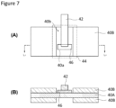
- FIG. 7 is a configurational diagram of a positive electrode of the lithium secondary battery described in PATENT LITERATURE 1
- FIG. 7(A) is a partial top view viewed from a one principal surface-side of the current collector
- FIG. 7(B) is a sectional view taken along the line L1-L1 in FIG. 7(A) .
- an insulating tape 44 disposed at the one principal surface-side of a positive electrode current collector 40A covers a positive electrode current collector exposed surface 40a at a both-surface non-coated portion 40b on which no positive electrode mixture layer 40B is formed, a positive electrode lead 42 above the positive electrode current collector exposed surface 40a, and a protective layer 46 interposed between a lower end part of the positive electrode lead 42 and the positive electrode current collector exposed surface 40a.
- This insulating tape 44 is provided to prevent heat generation in a battery when a separator or the like splits at the time of battery abnormality and the positive electrode and a negative electrode come into contact with each other, for example.
- the insulating tape includes a first adhesive layer, a second organic layer, a second adhesive layer, and a first organic layer that are disposed in that order from the side on which the positive electrode lead is located. All of these layers have the same width.
- An object of the present disclosure is to provide a secondary battery, an insulating member, and a positive electrode lead capable of suppressing an increase in battery temperature when an insulating tape covering a positive electrode lead breaks due to a foreign matter.
- an increase in battery temperature which occurs when the insulating tape covering the positive electrode lead breaks due to a foreign matter may be suppressed.
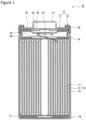
- FIG. 1 is a sectional view of a secondary battery according to an embodiment.
- the secondary battery 10 shown in FIG. 1 is one example of a lithium ion secondary battery.
- the secondary battery according to the embodiment is not limited to a lithium ion secondary battery and may be other secondary batteries such as an alkaline secondary battery.
- the secondary battery 10 shown in FIG. 1 comprises a wound-type electrode assembly 14 in which a positive electrode 11 and a negative electrode 12 are wound with a separator 13 interposed therebetween, an electrolyte, insulating plates 18, 19 respectively disposed at the upper and lower sides of the electrode assembly 14, a positive electrode lead 20 and a negative electrode lead 21, an insulating tape (not shown) covering a part of the positive electrode lead 20, and a battery case 15 housing these members described above.
- the secondary battery 10 may comprise an insulating member covering the negative electrode lead 21.
- the electrode assembly 14 is not limited to such a wound-type electrode assembly, and other forms such as a laminated-type electrode assembly in which a positive electrode and a negative electrode are alternately laminated with a separator interposed therebetween may be employed, for example.
- the battery case 15 comprises a bottomed cylindrical case body 16 having an opening, and a sealing assembly 17 sealing the opening of the case body 16, for example.
- the battery case 15 desirably comprises a gasket 28 provided between the case body 16 and the sealing assembly 17, and sealability inside the battery is secured thereby.
- the shape of the battery case 15 is not limited to a cylindrical shape, and the battery case 15 may be a square shape, a laminate-type, and the like, for example.
- the case body 16 has a projecting portion 22 in which a part of a side surface thereof inwardly projects and which supports the sealing assembly 17, for example.
- the projecting portion 22 is preferably formed into an annular shape along a circumferential direction of the case body 16 and supports the sealing assembly 17 with its upper surface.
- the sealing assembly 17 has a structure in which a filter 23, a lower vent member 24, an insulator 25, an upper vent member 26, and a cap 27 are laminated from the side of the electrode assembly 14 in this order.
- Each member configuring the sealing assembly 17 has a disc shape or a ring shape, for example, and the members other than the insulator 25 are electrically connected to each other.
- the lower vent member 24 and the upper vent member 26 are connected to each other at their respective central parts, and the insulator 25 is interposed between respective peripheral parts of the lower vent member 24 and the upper vent member 26.
- the lower vent member 24 deforms so as to push up the upper vent member 26 toward the side of the cap 27 and breaks, and a current path between the lower vent member 24 and the upper vent member 26 is cut off, for example.
- the upper vent member 26 breaks, and gas is discharged from an opening of the cap 27.
- the positive electrode lead 20 has a first end part (not shown), an extension part 20b, and a second end part 20c; the first end part is connected to the positive electrode 11; the extension part 20b extending from the first end part extends toward the sealing assembly 17 through a through hole of the insulating plate 18; and the second end part 20c positioned closer to a leading end than the extension part 20b is connected to a lower surface of the filter 23 of the sealing assembly 17 as described later. Consequently, the cap 27 electrically connected to the filter 23 becomes a positive electrode terminal.
- each of the second end part of the positive electrode lead 20 and the other end of the negative electrode lead 21 may be connected at a position opposite to the above described position.
- the second end part of the positive electrode lead 20 may be connected to the case body 16, and the other end of the negative electrode lead 21 may be connected to the lower surface of the filter 23 of the sealing assembly 17.
- the positive electrode lead 20 does not have the second end part 20c connected to the battery case 15.
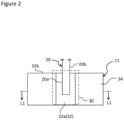
- the insulating tape 30 is illustrated by an alternate long and short dash line as a transmissive image in FIG.2 .
- the positive electrode 11 comprises a positive electrode current collector 32 and a positive electrode active material layer 34 formed on the positive electrode current collector 32. Foil of a metal stable in an electric potential range of the positive electrode such as aluminum, a film in which said metal is disposed on a surface layer thereof, and the like are used for the positive electrode current collector 32.
- the positive electrode active material layer 34 includes a positive electrode active material.
- the positive electrode active material layer 34 preferably includes a conductive agent and a binder in addition to the positive electrode active material.
- Examples of the positive electrode active material included in the positive electrode active material layer 34 include a lithium-transition metal composite oxide. Specifically, lithium cobaltate, lithium manganate, lithium nickelate, a lithium nickel manganese composite oxide, a lithium nickel cobalt composite oxide, and the like can be used as the positive electrode active material, and Al, Ti, Zr, Nb, B, W, Mg, Mo, and the like may be added to these lithium-transition metal composite oxides.
- Examples of the conductive agent included in the positive electrode active material layer 34 include carbon powder such as carbon black, acetylene black, Ketjen black, and graphite. These conductive agents may be used singly, or two or more kinds thereof may be used in combination.
- the positive electrode current collector 32 has an exposed part 32a on which the positive electrode active material layer 34 is not formed.
- the exposed part 32a illustrated in FIG. 2 is formed at a longitudinally central part of the positive electrode current collector 32.
- the exposed part 32a may be formed at any position of the positive electrode current collector 32 and may be formed at a longitudinally end part of the positive electrode current collector 32, for example.
- the positive electrode lead 20 comprises a first end part 20a connected to the exposed part 32a of the positive electrode current collector 32, an extension part 20b extending from the first end part 20a toward an outside of a peripheral part 32b of the positive electrode current collector 32.
- the positive electrode lead 20 has the second end part 20c (see FIG. 1 ) in a leading end side of the extension part 20b and is connected to the filter 23 of the sealing assembly 17 as described above.
- a method for connecting the first end part 20a of the positive electrode lead 20 and the exposed part 32a of the positive electrode current collector 32 and a method for connecting the second end part 20c of the positive electrode lead 20 and the sealing assembly 17 are not particularly limited as long as electrical connection is secured, and examples thereof include ultrasonic welding.
- a material for the positive electrode lead 20 is not particularly limited and includes a metal such as aluminum and titanium.
- the negative electrode 12 comprises a negative electrode current collector and a negative electrode active material layer formed on the negative electrode current collector. Foil of a metal stable in an electric potential range of the negative electrode such as copper, a film in which said metal is disposed on a surface layer thereof, and the like are used for the negative electrode current collector.
- the negative electrode active material layer includes a negative electrode active material.
- the negative electrode active material layer preferably includes a thickener and a binder in addition to the negative electrode active material.
- the negative electrode active material a carbon material capable of occluding and releasing lithium ions can be used, and hardly graphitizable carbon, easily graphitizable carbon, fibrous carbon, coke, carbon black, and the like can be used besides graphite. Furthermore, silicon, tin, and an alloy and oxide mainly containing them can be used as a non-carbon-based material.
- binder While PTFE and the like can be used as with the case of the positive electrode, a styrene-butadiene copolymer (SBR) or a modified product thereof and the like may be used.
- SBR styrene-butadiene copolymer
- thickener carboxymethyl cellulose (CMC) and the like may be used.
- the electrolyte includes a solvent and an electrolyte salt dissolved in the solvent.
- the electrolyte is not limited to a liquid electrolyte and may be a solid electrolyte using a gelatinous polymer and the like.
- the solvent is preferably a non-aqueous solvent such as carbonates, lactones, ethers, ketones, esters, and a mixed solvent of two or more kinds thereof, for example.
- the solvent may be an aqueous solvent.
- LiPF 6 LiPF 6 , LiBF 4 , LiCF 3 SO 3 , and a mixture of two or more kinds thereof can be used, for example.
- a dissolved amount of the electrolyte salt based on the solvent is 0.5 to 2.0 mol/L, for example.
- a porous sheet having ion permeability and insulation properties is used for the separator 13, for example.
- the porous sheet include a fine porous thin film, a woven fabric, and a nonwoven fabric.
- an olefin-based resin such as polyethylene and polypropylene and cellulose are preferable.
- the separator 13 may be a laminated body having a cellulose fiber layer and a fiber layer of a thermoplastic resin such as an olefin-based resin.
- the separator 13 may be a multilayer separator including a polyethylene layer and a polypropylene layer, and a separator in which a material such as an aramid-based resin and a ceramic is applied to a surface thereof may be used.
- FIG. 3 is a sectional view taken along the line L1-L1 in FIG 2 .
- An insulating member covering a part of the positive electrode lead 20 has an insulating tape 30 and an insulating layer 36 described later.
- the insulating layer 36 is disposed on an outer surface of the first end part 20a of the positive electrode lead 20.
- the insulating layer 36 is preferably disposed on the exposed part 32a of the positive electrode current collector 32.
- the outer surface of the first end part 20a of the positive electrode lead 20 is a surface other than the part contacting the exposed part 32a of the positive electrode current collector 32. That is, in a case where the positive electrode lead 20 has a plate shape as shown in FIG. 2 , the outer surface of the first end part 20a includes one principal surface opposed to a surface contacting the exposed part 32a of the positive electrode current collector 32 and a pair of side surfaces opposed to each other.
- a shape of the positive electrode lead 20 is not limited to a plate shape and may be a columnar shape and the like.
- the insulating layer 36 is preferably disposed on the one principal surface and the pair of side surfaces of the first end part 20a of the positive electrode lead 20.
- the insulating layer 36 may be disposed on the entirety or a part of the outer surface of the first end part 20a of the positive electrode lead 20. That is, with respect to the positive electrode lead 20 having a plate shape, the insulating layer 36 may be disposed on a part or the entirety of the one principal surface of the first end part 20a, may be disposed on a part or the entirety of the pair of side surfaces, or may be disposed on a part or the entirety of each of the one principal surface and the pair of side surfaces of the first end part 20a.
- the insulating layer 36 may be formed on a surface of the first end part 20a of the positive electrode lead 20 contacting the exposed part 32a of the positive electrode current collector 32, in this case, contact resistance at a contact between the positive electrode lead 20 and the positive electrode current collector 32 may increase, and battery performance may deteriorate. Accordingly, in the first end part 20a of the positive electrode lead 20, the insulating layer 36 is preferably not disposed on the surface contacting the exposed part 32a of the positive electrode current collector 32.
- the insulating layer 36 has electrical resistance higher than that of a native oxide film naturally foamed on the positive electrode lead 20.
- the insulating layer 36 preferably has electrical resistance of 1 M ⁇ or more and more preferably has electrical resistance of 10 M ⁇ or more, for example.
- a material of the insulating layer 36 is not particularly limited as long as the insulating layer 36 includes a material having insulation properties and the like.
- the insulating layer 36 preferably includes an inorganic material.
- the insulating layer 36 preferably includes a binder in terms of mechanical strength, adhesiveness, and the like of the insulating layer 36.
- the inorganic material included in the insulating layer 36 includes at least one selected from the group consisting of a metal oxide, a metal hydroxide, a metal nitride, a metal fluoride, and a metal carbide, for example.
- the binder included in the insulating layer 36 is preferably a substance dissolvable in a solvent such as NMP and water, for example, and chemically stable in the positive electrode.
- a solvent such as NMP and water
- examples thereof include polytetrafluoroethylene (PTFE), polyvinylidene difluoride (PVdF), polyacrylic acid, polyacrylonitrile, polyisobutylene, and polyisoprene.
- the insulating tape 30 is disposed at both of the one principal surface-side and the other principal surface-side of the positive electrode 11.
- the insulating tape 30 may be disposed at the one principal surface-side of the positive electrode 11 on which the positive electrode lead 20 is disposed.
- the insulating tape 30 disposed at the one principal surface-side covers the insulating layer 36 disposed on the outer surface of the first end part 20a of the positive electrode lead 20.
- the insulating tape 30 disposed at the one principal surface-side preferably covers the insulating layer 36 disposed on the exposed part 32a of the positive electrode current collector 32 and also covers a boundary part between the exposed part 32a and the positive electrode active material layer 34.
- the insulating tape 30 disposed at the other principal surface-side covers the exposed part 32a and a boundary part between the exposed part 32a and the positive electrode active material layer 34.
- the insulating tape 30 includes a substrate layer and an adhesive layer on the substrate layer, for example.
- the substrate layer is a layer mainly containing an organic material, for example, and examples thereof include polyphenylene sulfide (PPS), polyetheretherketone (PEEK), polyimide (PI), polypropylene (PP), polyethylene terephthalate (PET), and polybutylene terephthalate (PBT).
- the adhesive layer is a layer adhering to the insulating layer 36, the exposed part 32a, and the like and preferably includes an adhesive such as a rubber-based resin, an acrylic resin, and a silicone-based resin, for example.
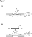
- FIG. 4 is a diagram showing one example of a method for arranging the insulating layer and the insulating tape.
- slurry including inorganic particles, a binder, and the like is applied on the outer surface of the first end part 20a of the positive electrode lead 20 and on the exposed part 32a to dispose the insulating layer 36 on the outer surface of the first end part 20a and on the exposed part 32a (see FIG. 4(A) ).
- the insulating tape 30 having the substrate layer 30a and the adhesive layer 30b on the substrate layer 30a is prepared, and the insulating tape 30 is attached on the insulating layer 36, with the adhesive layer 30b facing the insulating layer 36 (see FIG. 4(B) ).
- the insulating layer 36 prepared according to such a procedure is in a state of adhering to the first end part 20a and the exposed part 32a.
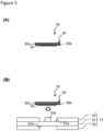
- FIG. 5 is a diagram showing another example of the method for arranging the insulating layer and the insulating tape.
- the insulating layer 36 including inorganic particles, a binder, and the like is formed on the adhesive layer 30b of the insulating tape 30 having the substrate layer 30a and the adhesive layer 30b on the substrate layer 30a to prepare an insulating member 39. (See FIG. 5(A) ).
- the insulating member 39 is attached so that the insulating layer 36 of the insulating member 39 is disposed on the outer surface of the first end part 20a and on the exposed part 32a (see FIG. 5(B) ).
- the insulating layer 36 prepared according to such a procedure is in a state of not adhering to the first end part 20a and the exposed part 32a.
- the insulating layer 36 may be only disposed on the outer surface of the first end part 20a of the positive electrode lead 20, the insulating layer 36 is preferably disposed on a part or the entirety of the exposed part 32a as described above. Consequently, a foreign matter having entered a battery hardly comes into contact with the exposed part 32a, and occurrence of an internal short circuit in the battery is further suppressed.
- a thickness of the insulating layer 36 is preferably within a range of 2 to 30 ⁇ m, for example.
- occurrence of an internal short circuit or an increase in battery temperature, which arises when the insulating tape 30 breaks due to a foreign matter is suppressed compared with a case where the thickness of the insulating layer 36 is less than 2 ⁇ m.
- An insulating layer 36 having a thickness exceeding 30 ⁇ m may require other components to have reduced volumes so as to allow the case body 16 with a predetermined size to house the electrode assembly 14.
- Examples of the inorganic material in the insulating layer 36 include a metal oxide such as aluminum oxide, titanium oxide, zirconium oxide, silicon oxide, manganese oxide, magnesium oxide, and nickel oxide; a metal hydroxide such as aluminum hydroxide and magnesium hydroxide; a metal nitride such as titanium nitride, boron nitride, aluminum nitride, magnesium nitride, and silicon nitride; a metal fluoride such as aluminum fluoride, lithium fluoride, sodium fluoride, magnesium fluoride, calcium fluoride, and barium fluoride; and a metal carbide such as silicon carbide, boron carbide, titanium carbide, and tungsten carbide.
- the inorganic material preferably includes at least one of the group consisting of aluminum oxide, aluminum hydroxide, titanium oxide, magnesium oxide, and magnesium hydroxide in terms of chemical stability against the electrolyte and the like.
- a basis weight of the inorganic material in the insulating layer 36 is preferably 0.5 to 10 mg/cm 2 .
- the basis weight of the inorganic material is 0.5 mg/cm 2 or more, an increase in battery temperature due to an internal short circuit is suppressed compared to a case where the basis weight of the inorganic material is less than 0.5 mg/cm 2 .
- An insulating layer 36 in which a basis weight of the inorganic material exceeds 10 mg/cm 2 is undesirable because costs may increase.
- An average particle diameter of the inorganic material is preferably within a range of 0.05 to 2.0 ⁇ m because an increase in battery temperature due to an internal short circuit can be further suppressed thereby and other reasons.
- the average particle diameter is a volume average particle diameter measured by a laser diffraction method and means a median diameter at which a volumetric integrated value becomes 50% in a particle size distribution.
- the average particle diameter can be measured using a laser diffraction and scattering-type particle size distribution measuring device (manufactured by HORIBA, Ltd.), for example.
- the insulating tape 30 may only cover the insulating layer 36 disposed on the first end part 20a of the positive electrode lead 20, the insulating tape 30 preferably further covers the insulating layer 36 disposed on the exposed part 32a and more preferably covers a part or the entirety of the boundary part between the exposed part 32a and the positive electrode active material layer 34. Consequently, a foreign matter having entered a battery hardly comes into contact with the exposed part 32a or the boundary part, and occurrence of an internal short circuit in the battery is further suppressed. Furthermore, the insulating tape 30 may cover a part or the entirety of the extension part 20b of the positive electrode lead 20. Consequently, deterioration of battery performance due to contact of the positive electrode lead 20 with other members is suppressed.
- a thickness of the insulating tape 30 is not particularly limited but is preferably within a range of 10 to 40 ⁇ m, for example. When the thickness of the insulating tape 30 is less than 10 ⁇ m, breakage is easily caused by a foreign matter having entered a battery. In addition, when the thickness of the insulating tape 30 exceeds 40 ⁇ m, other components may be required to have reduced volumes so that the case body 16 with a predetermined size is allowed to house the electrode assembly 14.
- a positive electrode active material 100 parts by weight of a lithium nickel cobalt aluminum composite oxide represented by LiNi 0.88 Co 0.09 Al 0.03 O 2 , one part by weight of acetylene black (AB), and one part by weight of polyvinylidene difluoride (PVDF) were mixed; and an appropriate amount of N-methyl-2-pyrolidone (NMP) was further added thereto to prepare positive electrode mixture slurry. Thereafter, the positive electrode mixture slurry was applied to both sides of a positive electrode current collector made from aluminum foil and dried. The resultant product was cut into a predetermined electrode size and rolled by using a roller to prepare a positive electrode with a positive electrode active material layer formed on the both sides of the positive electrode current collector.
- NMP N-methyl-2-pyrolidone
- An exposed part (width: 6 mm) on which no positive electrode active material layer was formed and the positive electrode current collector was exposed was formed approximately at a central part in the longitudinal direction of the positive electrode.
- An aluminum positive electrode lead having a thickness of 150 ⁇ m and a width of 3.5 mm was bonded to the formed exposed part by ultrasonic welding.
- An insulating tape in which an adhesive layer (thickness: 7 ⁇ m) made from an acrylic adhesive was formed on a substrate layer made from a polyimide film having a width of 11 mm and a thickness of 25 ⁇ m was prepared.
- the insulating layer formed on the PET film was attached to the adhesive layer of the insulating tape, the PET film was subsequently peeled, and the insulating layer (width: 7 mm) was transferred on the adhesive layer to prepare an insulating member.
- the insulating member was attached so that the insulating layer of the insulating member was disposed on the outer surface of first end part of the positive electrode lead and on the exposed part. That is, the insulating layer disposed on the outer surface of the first end part of the positive electrode lead and on the exposed part was covered with the insulating tape.
- negative electrode current collector a thin plate of copper foil was used as a negative electrode current collector; negative electrode mixture slurry was prepared by dispersing a graphite powder, carboxymethyl cellulose (CMC) as a thickener, and styrene-butadiene rubber (SBR) as a binder in water at a ratio of 98:1:1 in terms of respective mass ratios; the negative electrode mixture slurry was applied to both sides of the current collector and dried; and the resultant product was compressed by roll pressing so as to have a predetermined thickness. An exposed part on which no negative electrode active material layer was formed and the negative electrode current collector was exposed was formed at an end part of the negative electrode in the longitudinal direction, and a nickel negative electrode lead was bonded to the exposed part by ultrasonic welding.
- CMC carboxymethyl cellulose
- SBR styrene-butadiene rubber
- the insulating tape was obtained by forming an adhesive layer made from a rubber-based resin on a substrate layer made from a polypropylene film having a thickness of 25 ⁇ m.
- a wound-type electrode assembly was prepared by spirally winding the prepared positive electrode and negative electrode with a separator interposed therebetween.
- a polyethylene fine porous film with a heat resistant layer in which a filler including polyamide and alumina was dispersed formed on one surface thereof was used as the separator.
- the above-described electrode assembly was housed in a bottomed cylindrical case body having an outer diameter of 18 mm and a height of 65 mm. At this time, the second end part of the positive electrode lead was welded to a sealing assembly, and the other end of the negative electrode lead was welded to the case body.
- a non-aqueous electrolytic solution in which LiPF 6 was added to a mixed solvent obtained by mixing ethylene carbonate (EC), ethyl methyl carbonate (EMC), and diethyl carbonate (DEC) at a volume ratio of 3:3:4 so that a concentration of LiPF 6 became 1 mol/L was injected to the case body, and the opening of the case body was subsequently sealed by a gasket and the sealing assembly to prepare a 18650 cylindrical non-aqueous electrolyte secondary battery.
- EC ethylene carbonate
- EMC ethyl methyl carbonate
- DEC diethyl carbonate
- a non-aqueous electrolyte secondary battery was prepared in the same manner as Example A1 except that the basis weight of aluminum oxide in the insulating layer was changed to 2.5 mg/cm 2 .
- a non-aqueous electrolyte secondary battery was prepared in the same manner as Example A1 except that the basis weight of aluminum oxide in the insulating layer was changed to 10 mg/cm 2 .
- a non-aqueous electrolyte secondary battery was prepared in the same manner as Example A1 except that the average particle diameter of aluminum oxide in the insulating layer was changed to 0.5 ⁇ m.
- a non-aqueous electrolyte secondary battery was prepared in the same manner as Example A1 except that the average particle diameter of aluminum oxide in the insulating layer was changed to 0.5 ⁇ m and the basis weight of aluminum oxide in the insulating layer was changed to 2.5 mg/cm 2 .
- a non-aqueous electrolyte secondary battery was prepared in the same manner as Example A1 except that the average particle diameter of aluminum oxide in the insulating layer was changed to 0.5 ⁇ m and the basis weight of aluminum oxide in the insulating layer was changed to 10 mg/cm 2 .
- a non-aqueous electrolyte secondary battery was prepared in the same manner as Example A1 except that the average particle diameter of aluminum oxide in the insulating layer was changed to 0.05 ⁇ m.
- a non-aqueous electrolyte secondary battery was prepared in the same manner as Example A1 except that the average particle diameter of aluminum oxide in the insulating layer was changed to 0.05 ⁇ m and the basis weight of aluminum oxide in the insulating layer was changed to 2.5 mg/cm 2 .
- a non-aqueous electrolyte secondary battery was prepared in the same manner as Example A1 except that the average particle diameter of aluminum oxide in the insulating layer was changed to 0.05 ⁇ m and the basis weight of aluminum oxide in the insulating layer was changed to 10 mg/cm 2 .
- An insulating layer was formed by applying slurry in which 95 parts by weight of aluminum oxide (average particle diameter: 1 ⁇ m) and 5 parts by weight of PVDF were dispersed in NMP to the outer surface of a first end part of a positive electrode lead and an exposed part and drying the slurry.
- the basis weight of aluminum oxide in the formed insulating layer was 1 mg/cm 2 .
- An insulating tape was attached so as to cover the formed insulating layer.
- the insulating tape was obtained by forming an adhesive layer (thickness: 7 ⁇ m) made from an acrylic adhesive on a substrate layer made from a polyimide film having a width of 11 mm and a thickness of 25 ⁇ m.
- a non-aqueous electrolyte secondary battery was prepared in the same manner as Example A1 except that the insulating layer was not disposed on the outer surface of the first end part of the positive electrode lead and the exposed part.
- Battery temperature at the time of short circuit due to a foreign matter was measured with respect to each of the non-aqueous electrolyte secondary batteries of Examples and Comparative Example.
- the battery temperature at the time of short circuit due to a foreign matter is the highest arrival temperature obtained by putting a foreign matter (a small nickel piece) on an insulating tape and measuring a temperature of the side surface of a battery with a thermocouple at the time of forcibly causing a short circuit according to JIS C 8714. Results of respective Examples and Comparative Example are shown in Table 1.
- Example A1 Insulating layer Battery temperature at time of short circuit due to foreign matter (degree C) Formation place Inorganic material Material Average particle diameter (um) Basis weight (mg/cm 2 ) Example A1 2 0.5 34 Example A2 2 2.5 31 Example A3 2 10 28 Example A4 0.5 0.5 30 Example A5 Formed on adhesive layer 0.5 2. 5 29 Example A6 Aluminum oxide 0.5 10 25 Example A7 0.05 0.5 28 Example A8 0.05 2.5 25 Example A9 0.05 10 25 Example A10 Formed on positive electrode lead 1 2.5 25 Comparative Example 1 - - - - 79
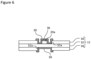
- an insulating layer 36 is formed on the outer surface of the first end part 20a of the positive electrode lead 20.
- the insulating layer 36 is formed on one principal surface of the first end part 20a of the positive electrode lead 20 in FIG. 6 , its configuration is not limited thereto, and the insulating layer 36 may be formed on the entirety or a part of the outer surface of the first end part 20a of the positive electrode lead 20. That is, in a plate-shaped positive electrode lead 20, the insulating layer 36 may be formed on a part or the entirety of the one principal surface of the first end part 20a, may be formed on a part or the entirety of a pair of side surfaces, or may be formed on a part or the entirety of the one principal surface and the pair of side surfaces of the first end part 20a.
- the insulating layer 36 is different from a native oxide film naturally foamed on the positive electrode lead 20 and has electrical resistance higher than that of a native oxide film.
- the insulating layer 36 preferably has electrical resistance of 1 M ⁇ or more and more preferably has electrical resistance of 10 M ⁇ or more, for example.
- examples of the insulating layer 36 include an oxide film such as an anodized film, a phosphate film, a chromate film (chromic acid salt film), a stannate film, and a fluoride film
- the insulating layer 36 is preferably an oxide film such as an anodized film or a phosphate film in terms of insulating properties, denseness, and the like.
- the phosphate film is formed by immersing the positive electrode lead 20 including aluminum or an alloy mainly containing aluminum in a phosphate solution for a predetermined time, for example.
- the positive electrode lead 20 after being immersed in the solution is desirably subjected to drying treatment at a temperature ranging from 30°C to 50°C, for example.
- a solution including phosphoric acid, chromic anhydride, and a fluoride or a solution including phosphoric acid, zinc phosphate monobasic, and a fluoride is preferably used as the phosphate solution in terms of obtaining an insulating layer 36 with higher insulation properties and denseness, and the like, for example.
- a phosphoric chromate film (specific compositions thereof are Al 2 O 3 , CrPO 4 , and the like, for example) is formed by immersing the positive electrode lead 20 in a solution including phosphoric acid, chromic anhydride, and a fluoride.
- a zinc phosphate film (specific compositions thereof are Zn 3 (PO 4 ) 2 , AlPO 4 , and the like, for example) is formed by immersing the positive electrode lead 20 in a solution including phosphoric acid, zinc phosphate monobasic, and a fluoride.
- the anodized film is formed by methods defined in JIS H 9500 and JIS H 9501, for example.
- An anodized film (alumite) is formed by immersing the positive electrode lead 20 including aluminum or an alloy mainly containing aluminum in a 20% sulfuric acid solution followed by anodization with an applied voltage of 20 V, for example.
- a specific composition of the anodized film is aluminum oxide or the like, for example.
- the solution is not limited to sulfuric acid and may be phosphoric acid, oxalic acid, or the like, for example.
- oxide film other than the anodized film examples include a boehmite film, and the like. These oxide films are formed by hydrothermal treatment and the like, for example. Among the oxide films, the anodized film is preferable in terms of obtaining an oxide film with high insulation properties and denseness.
- the insulating layer 36 may have a monolayer structure including the oxide film such as the anodized film, the phosphate film, or the like or may have a laminated structure in which the oxide film such as the anodized film and the phosphate film or the like are laminated.
- the insulating tape 30 shown in FIG. 2 and FIG. 6 is disposed on both of the one principal surface-side and the other principal surface-side of the positive electrode 11, the insulating tape 30 may be disposed at the one principal surface-side of the positive electrode 11 on which the positive electrode lead 20 is disposed.
- the insulating tape 30 disposed on the one principal surface-side covers the insulating layer 36 formed on the first end part 20a of the positive electrode lead 20, the exposed part 32a, and the boundary part between the exposed part 32a and the positive electrode active material layer 34.
- the insulating tape 30 disposed on the other principal surface-side covers the exposed part 32a and the boundary part between the exposed part 32a and the positive electrode active material layer 34.
- the insulating tape 30 may include at least the substrate layer, and the adhesive layer is not an essential component.
- an adhesive may be applied to a part for attachment, and the insulating tape may be attached on, for example.
- the insulating layer 36 may be formed on the outer surface of the first end part 20a of the positive electrode lead 20, the insulating layer 36 is preferably further formed on the extension part 20b of the positive electrode lead 20. Consequently, conduction between the positive electrode lead 20 and other members due to contact therebetween is suppressed, and deterioration of battery performance is suppressed.
- the insulating layer 36 may be formed on a part of the extension part 20b or may be formed on the entirety of the extension part 20b.
- the insulating layer 36 may be formed on the second end part 20c (see FIG. 1 ) of the positive electrode lead 20. However, when the insulating layer 36 is formed on the second end part 20c of the positive electrode lead 20, contact resistance against the sealing assembly 17 shown in FIG. 1 increases, and battery performance may deteriorate. Accordingly, the insulating layer 36 is preferably not formed on the second end part 20c of the positive electrode lead 20.
- a thickness of the insulating layer 36 is preferably within a range of 2 to 30 ⁇ m, for example.
- occurrence of an internal short circuit or an increase in battery temperature, which arises when the insulating tape 30 breaks due to a foreign matter is suppressed compared with a case where the thickness of the insulating layer 36 is less than 2 ⁇ m.
- An insulating layer 36 having a thickness exceeding 30 ⁇ m is not desirable because time and costs for film formation increase.
- Puncture breaking strength of the insulating layer 36 is preferably higher than puncture breaking strength of the insulating tape 30. Consequently, occurrence of an internal short circuit in a battery can be efficiently suppressed.
- a measurement method of puncture breaking strength will be described in the examples section.
- the insulating tape 30 may cover the insulating layer 36 formed on the first end part 20a of the positive electrode lead 20, the insulating tape 30 desirably further covers a part or the entirety of the exposed part 32a and a part or the entirety of the boundary part between the exposed part 32a and the positive electrode active material layer 34. Consequently, a foreign matter having entered a battery hardly comes into contact with the exposed part 32a or the boundary part, and occurrence of an internal short circuit in a battery is further suppressed. Furthermore, the insulating tape 30 may cover a part or the entirety of the extension part 20b of the positive electrode lead 20. Consequently, an internal short circuit due to contact of the positive electrode lead 20 with other members is suppressed.
- a positive electrode active material 100 parts by weight of a lithium nickel cobalt aluminum composite oxide represented by LiNi 0.88 Co 0.00 Al 0.03 O 2 , one part by weight of acetylene black (AB), and one part by weight of polyvinylidene difluoride (PVdF) were mixed; and an appropriate amount of N-methyl-2-pyrolidone (NMP) was further added thereto to prepare positive electrode mixture slurry. Thereafter, the positive electrode mixture slurry was applied to both sides of a positive electrode current collector made from aluminum foil and dried. The resultant product was cut into a predetermined electrode size and rolled by using a roller to prepare a positive electrode, with a positive electrode active material layer formed on the both sides of the positive electrode current collector. An exposed part on which no positive electrode active material layer was formed and the positive electrode current collector was exposed was formed approximately at a central part in the longitudinal direction of the positive electrode.
- An aluminum positive electrode lead having a thickness of 150 ⁇ m and a width of 3.5 mm was cut to have a predetermined length. Parts of this positive electrode lead to which the exposed part of the positive electrode current collector and a sealing assembly are respectively welded were masked, and the positive electrode lead was subsequently immersed in a 20% sulfuric acid solution followed by anodization with an applied voltage of 20 V to form an anodized film having a thickness of 2 ⁇ m on the positive electrode lead.
- Puncture breaking strength of the anodized film was 1 N. Puncture breaking strength of the anodized film was measured as follows. The anodized film on the positive electrode lead is pressed by a stainless-steel nail (diameter: 3 mm, tip angle: 35°), and electrical resistance between the stainless-steel nail and the positive electrode lead is measured while increasing the load of the stainless-steel nail. Then, the load applied at a time when electrical resistance indicating dielectric breakdown is observed is taken as puncture breaking strength.
- a part of the positive electrode lead on which no anodized film was formed was brought into contact with the exposed part of the positive electrode current collector and bonded to the exposed part by ultrasonic welding. That is, the positive electrode lead had a first end part connected to the exposed part, an extension part extending toward an outside of a peripheral part of the positive electrode current collector, and a second end part connected to a sealing assembly at a leading end side of the extension part and became a positive electrode lead with the anodized film formed on an outer surface of the first end part and the extending part thereof.
- negative electrode current collector a thin plate of copper foil was used as a negative electrode current collector; negative electrode mixture slurry was prepared by dispersing a graphite powder, carboxymethyl cellulose (CMC) as a thickener, and styrene-butadiene rubber (SBR) as a binder in water at a ratio of 98:1:1 in terms of respective mass ratios; the negative electrode mixture slurry was applied to both sides of the current collector and dried; and the resultant product was compressed by roll pressing so as to have a predetermined thickness. An exposed part on which no negative electrode active material layer was formed and the negative electrode current collector was exposed was formed at an end part of the negative electrode in the longitudinal direction, and a nickel negative electrode lead was bonded to the exposed part by ultrasonic welding.
- CMC carboxymethyl cellulose
- SBR styrene-butadiene rubber
- the anodized film formed on an outer surface of the first end part of the positive electrode lead and the exposed part were covered with an insulating tape.
- the negative electrode lead on the exposed part and the exposed part were covered with the insulating tape.
- the insulating tape used included a substrate layer made from a polyimide film having a thickness of 25 ⁇ m and an adhesive layer made from a rubber-based resin.
- Puncture breaking strength of the insulating tape was 2 N. Puncture breaking strength of the insulating tape was measured as follows. The insulating tape attached to an aluminum plate having a thickness of 150 ⁇ m is pressed by a stainless-steel nail (diameter: 3 mm, tip angle: 35°), and electrical resistance between the stainless-steel nail and the aluminum plate is measured while increasing the load of the stainless-steel nail. Then, the load applied at a time when electrical resistance indicating dielectric breakdown is observed is taken as puncture breaking strength.
- a wound-type electrode assembly was prepared by spirally winding the prepared positive electrode and negative electrode with a separator interposed therebetween.
- a polyethylene fine porous film with a heat resistant layer in which a filler including polyamide and alumina was dispersed formed on one surface thereof was used as the separator.
- the above-described electrode assembly was housed in a bottomed cylindrical case body having an outer diameter of 18 mm and a height of 65 mm. At this time, the second end part of the positive electrode lead was welded to a sealing assembly, and the other end of the negative electrode lead was welded to the case body.
- a non-aqueous electrolytic solution in which LiPF 6 was added to a mixed solvent obtained by mixing ethylene carbonate (EC), ethyl methyl carbonate (EMC), and diethyl carbonate (DEC) at a volume ratio of 3:3:4 so that a concentration of LiPF 6 became 1 mol/L was injected to the case body, and the opening of the case body was subsequently sealed by a gasket and the sealing assembly to prepare a 18650 cylindrical non-aqueous electrolyte secondary battery.
- EC ethylene carbonate
- EMC ethyl methyl carbonate
- DEC diethyl carbonate
- a non-aqueous electrolyte secondary battery was prepared in the same manner as Example B1 except that an anodized film having a thickness of 10 ⁇ m was formed on the positive electrode lead by adjusting the electric quantity during anodization treatment. Puncture breaking strength of the anodized film was 2 N.
- a non-aqueous electrolyte secondary battery was prepared in the same manner as Example B1 except that an anodized film having a thickness of 15 ⁇ m was formed on the positive electrode lead by adjusting the electric quantity during anodization treatment. Puncture breaking strength of the anodized film was 2.7 N.
- a non-aqueous electrolyte secondary battery was prepared in the same manner as Example B1 except that an anodized film having a thickness of 20 ⁇ m was formed on the positive electrode lead by adjusting the electric quantity during anodization treatment. Puncture breaking strength of the anodized film was 3.1 N.
- a non-aqueous electrolyte secondary battery was prepared in the same manner as Example B1 except that an anodized film having a thickness of 25 ⁇ m was formed on the positive electrode lead by adjusting the electric quantity during anodization treatment. Puncture breaking strength of the anodized film was 3.5 N.
- a non-aqueous electrolyte secondary battery was prepared in the same manner as Example B1 except that an anodized film having a thickness of 30 ⁇ m was formed on the positive electrode lead by adjusting the electric quantity during anodization treatment. Puncture breaking strength of the anodized film was 3.7 N.
- a non-aqueous electrolyte secondary battery was prepared in the same manner as Example B1 except that no anodized film was formed on the positive electrode lead.
Landscapes
- Chemical & Material Sciences (AREA)
- Chemical Kinetics & Catalysis (AREA)
- Electrochemistry (AREA)
- General Chemical & Material Sciences (AREA)
- Engineering & Computer Science (AREA)
- Manufacturing & Machinery (AREA)
- Crystallography & Structural Chemistry (AREA)
- Inorganic Chemistry (AREA)
- Connection Of Batteries Or Terminals (AREA)
- Battery Electrode And Active Subsutance (AREA)
- Secondary Cells (AREA)
Description
- The present invention relates to a secondary battery, an insulating member, and a positive electrode lead.
- Conventionally, a lithium secondary battery in which insulation properties of a positive electrode or a negative electrode are improved by using an insulating tape has been proposed.
- PATENT LITERATURE 1 describes a lithium secondary battery in which disconnection of a current collector at a part at which the current collector and a lead are in contact with each other is suppressed.
-
FIG. 7 is a configurational diagram of a positive electrode of the lithium secondary battery described in PATENT LITERATURE 1,FIG. 7(A) is a partial top view viewed from a one principal surface-side of the current collector, andFIG. 7(B) is a sectional view taken along the line L1-L1 inFIG. 7(A) . - As shown in
FIG. 7 , aninsulating tape 44 disposed at the one principal surface-side of a positive electrode current collector 40A covers a positive electrode current collector exposedsurface 40a at a both-surface non-coatedportion 40b on which no positiveelectrode mixture layer 40B is formed, apositive electrode lead 42 above the positive electrode current collector exposedsurface 40a, and aprotective layer 46 interposed between a lower end part of thepositive electrode lead 42 and the positive electrode current collector exposedsurface 40a. Thisinsulating tape 44 is provided to prevent heat generation in a battery when a separator or the like splits at the time of battery abnormality and the positive electrode and a negative electrode come into contact with each other, for example. - A further example of the prior art is disclosed in PATENT LITERATURE 1. Therein, the insulating tape includes a first adhesive layer, a second organic layer, a second adhesive layer, and a first organic layer that are disposed in that order from the side on which the positive electrode lead is located. All of these layers have the same width.
-
- PATENT LITERATURE 1:
Japanese Unexamined Patent Application Publication No. 2014-89856 - PATENT LITERATURE 2:
WO 2017/149961 A1 - However, when a foreign matter adheres onto the
insulating tape 44 covering thepositive electrode lead 42 and theinsulating tape 44 breaks due to the foreign matter or the like, an internal short circuit occurs between thepositive electrode lead 42 and the negative electrode, for example, which may lead to an increase in battery temperature. - An object of the present disclosure is to provide a secondary battery, an insulating member, and a positive electrode lead capable of suppressing an increase in battery temperature when an insulating tape covering a positive electrode lead breaks due to a foreign matter.
- The present invention is defined in the independent claim. Preferred embodiments are referred to in the dependent claims.
- According to the present disclosure, an increase in battery temperature which occurs when the insulating tape covering the positive electrode lead breaks due to a foreign matter may be suppressed.
-
-
FIG. 1 is a sectional view of a secondary battery according to an embodiment. -
FIG. 2 is a partial top view viewed from one principal surface-side of a positive electrode. -
FIG. 3 is a sectional view (first embodiment) taken along the line L1-L1 inFIG 2 . -
FIG. 4 is a diagram showing one example of a method for arranging an insulating layer and an insulating tape according to the first embodiment. -
FIG. 5 is a diagram showing another example of the method for arranging the insulating layer and the insulating tape according to the first embodiment. -
FIG. 6 is a sectional view (second embodiment) taken along the line L1-L1 inFIG 2 . -
FIG. 7 is a configurational diagram of a positive electrode of a lithium secondary battery described in PATENT LITERATURE 1. - Hereinafter, one example of a secondary battery which is one aspect of the present disclosure will be described. Figures referenced in the following description of embodiments are schematically illustrated, and dimension ratios or the like of components drawn in the figures may be different from actual ones.
-
FIG. 1 is a sectional view of a secondary battery according to an embodiment. Thesecondary battery 10 shown inFIG. 1 is one example of a lithium ion secondary battery. The secondary battery according to the embodiment is not limited to a lithium ion secondary battery and may be other secondary batteries such as an alkaline secondary battery. - The
secondary battery 10 shown inFIG. 1 comprises a wound-type electrode assembly 14 in which apositive electrode 11 and anegative electrode 12 are wound with aseparator 13 interposed therebetween, an electrolyte,insulating plates electrode assembly 14, apositive electrode lead 20 and anegative electrode lead 21, an insulating tape (not shown) covering a part of thepositive electrode lead 20, and abattery case 15 housing these members described above. Incidentally, thesecondary battery 10 may comprise an insulating member covering thenegative electrode lead 21. - The
electrode assembly 14 is not limited to such a wound-type electrode assembly, and other forms such as a laminated-type electrode assembly in which a positive electrode and a negative electrode are alternately laminated with a separator interposed therebetween may be employed, for example. - The
battery case 15 comprises a bottomedcylindrical case body 16 having an opening, and asealing assembly 17 sealing the opening of thecase body 16, for example. Thebattery case 15 desirably comprises agasket 28 provided between thecase body 16 and thesealing assembly 17, and sealability inside the battery is secured thereby. The shape of thebattery case 15 is not limited to a cylindrical shape, and thebattery case 15 may be a square shape, a laminate-type, and the like, for example. - The
case body 16 has a projectingportion 22 in which a part of a side surface thereof inwardly projects and which supports thesealing assembly 17, for example. The projectingportion 22 is preferably formed into an annular shape along a circumferential direction of thecase body 16 and supports thesealing assembly 17 with its upper surface. - The
sealing assembly 17 has a structure in which afilter 23, alower vent member 24, aninsulator 25, anupper vent member 26, and acap 27 are laminated from the side of theelectrode assembly 14 in this order. Each member configuring thesealing assembly 17 has a disc shape or a ring shape, for example, and the members other than theinsulator 25 are electrically connected to each other. Thelower vent member 24 and theupper vent member 26 are connected to each other at their respective central parts, and theinsulator 25 is interposed between respective peripheral parts of thelower vent member 24 and theupper vent member 26. When an inner pressure increases due to heat generated by an internal short circuit or the like, thelower vent member 24 deforms so as to push up theupper vent member 26 toward the side of thecap 27 and breaks, and a current path between thelower vent member 24 and theupper vent member 26 is cut off, for example. When the inner pressure further increases, theupper vent member 26 breaks, and gas is discharged from an opening of thecap 27. - The
positive electrode lead 20 has a first end part (not shown), anextension part 20b, and asecond end part 20c; the first end part is connected to thepositive electrode 11; theextension part 20b extending from the first end part extends toward thesealing assembly 17 through a through hole of theinsulating plate 18; and thesecond end part 20c positioned closer to a leading end than theextension part 20b is connected to a lower surface of thefilter 23 of thesealing assembly 17 as described later. Consequently, thecap 27 electrically connected to thefilter 23 becomes a positive electrode terminal. One end of thenegative electrode lead 21 is connected to thenegative electrode 12 and the other end of thenegative electrode lead 21 is connected to an inner surface of a bottom part of thecase body 16, with thenegative electrode lead 21 extending from thenegative electrode 12 through an outside of theinsulating plate 19. Consequently, thecase body 16 becomes a negative electrode terminal. Incidentally, each of the second end part of thepositive electrode lead 20 and the other end of thenegative electrode lead 21 may be connected at a position opposite to the above described position. For example, the second end part of thepositive electrode lead 20 may be connected to thecase body 16, and the other end of thenegative electrode lead 21 may be connected to the lower surface of thefilter 23 of thesealing assembly 17. Incidentally, while the positive electrode lead 20 ofFIG. 1 has thesecond end part 20c to be connected to thebattery case 15, in the case of a battery in which thebattery case 15 is not connected (for example, a square battery, a laminated battery, and the like), thepositive electrode lead 20 does not have thesecond end part 20c connected to thebattery case 15. - Hereinafter, the
positive electrode 11, the positive electrode lead 20, thenegative electrode 12, the electrolyte, and theseparator 13 will be described with reference toFIG. 1 andFIG. 2 . Theinsulating tape 30 is illustrated by an alternate long and short dash line as a transmissive image inFIG.2 . - The
positive electrode 11 comprises a positiveelectrode current collector 32 and a positive electrodeactive material layer 34 formed on the positive electrodecurrent collector 32. Foil of a metal stable in an electric potential range of the positive electrode such as aluminum, a film in which said metal is disposed on a surface layer thereof, and the like are used for the positiveelectrode current collector 32. The positive electrodeactive material layer 34 includes a positive electrode active material. In addition, the positive electrodeactive material layer 34 preferably includes a conductive agent and a binder in addition to the positive electrode active material. - Examples of the positive electrode active material included in the positive electrode
active material layer 34 include a lithium-transition metal composite oxide. Specifically, lithium cobaltate, lithium manganate, lithium nickelate, a lithium nickel manganese composite oxide, a lithium nickel cobalt composite oxide, and the like can be used as the positive electrode active material, and Al, Ti, Zr, Nb, B, W, Mg, Mo, and the like may be added to these lithium-transition metal composite oxides. - Examples of the conductive agent included in the positive electrode
active material layer 34 include carbon powder such as carbon black, acetylene black, Ketjen black, and graphite. These conductive agents may be used singly, or two or more kinds thereof may be used in combination. - Examples of the binder included in the positive electrode
active material layer 34 include a fluorine polymer and a rubber polymer. Examples of the fluorine polymer include polytetrafluoroethylene (PTFE), polyvinylidene fluoride (PVdF), and a modified product thereof, and examples of the rubber polymer include an ethylene-propylene-isoprene copolymer and an ethylene-propylene-butadiene copolymer. These binders may be used singly, or two or more kinds thereof may be used in combination. - The positive electrode
current collector 32 has an exposedpart 32a on which the positive electrodeactive material layer 34 is not formed. Incidentally, the exposedpart 32a illustrated inFIG. 2 is formed at a longitudinally central part of the positive electrodecurrent collector 32. Note that theexposed part 32a may be formed at any position of the positive electrodecurrent collector 32 and may be formed at a longitudinally end part of the positive electrodecurrent collector 32, for example. - The
positive electrode lead 20 comprises afirst end part 20a connected to the exposedpart 32a of the positive electrodecurrent collector 32, anextension part 20b extending from thefirst end part 20a toward an outside of aperipheral part 32b of the positive electrodecurrent collector 32. In addition, although not shown inFIG. 2 , thepositive electrode lead 20 has thesecond end part 20c (seeFIG. 1 ) in a leading end side of theextension part 20b and is connected to thefilter 23 of the sealingassembly 17 as described above. A method for connecting thefirst end part 20a of thepositive electrode lead 20 and theexposed part 32a of the positive electrodecurrent collector 32 and a method for connecting thesecond end part 20c of thepositive electrode lead 20 and the sealingassembly 17 are not particularly limited as long as electrical connection is secured, and examples thereof include ultrasonic welding. - A material for the
positive electrode lead 20 is not particularly limited and includes a metal such as aluminum and titanium. - The
negative electrode 12 comprises a negative electrode current collector and a negative electrode active material layer formed on the negative electrode current collector. Foil of a metal stable in an electric potential range of the negative electrode such as copper, a film in which said metal is disposed on a surface layer thereof, and the like are used for the negative electrode current collector. The negative electrode active material layer includes a negative electrode active material. The negative electrode active material layer preferably includes a thickener and a binder in addition to the negative electrode active material. - As the negative electrode active material, a carbon material capable of occluding and releasing lithium ions can be used, and hardly graphitizable carbon, easily graphitizable carbon, fibrous carbon, coke, carbon black, and the like can be used besides graphite. Furthermore, silicon, tin, and an alloy and oxide mainly containing them can be used as a non-carbon-based material.
- As the binder, while PTFE and the like can be used as with the case of the positive electrode, a styrene-butadiene copolymer (SBR) or a modified product thereof and the like may be used. As the thickener, carboxymethyl cellulose (CMC) and the like may be used.
- The electrolyte includes a solvent and an electrolyte salt dissolved in the solvent. The electrolyte is not limited to a liquid electrolyte and may be a solid electrolyte using a gelatinous polymer and the like. The solvent is preferably a non-aqueous solvent such as carbonates, lactones, ethers, ketones, esters, and a mixed solvent of two or more kinds thereof, for example. However, the solvent may be an aqueous solvent.
- As the electrolyte salt, LiPF6, LiBF4, LiCF3SO3, and a mixture of two or more kinds thereof can be used, for example. A dissolved amount of the electrolyte salt based on the solvent is 0.5 to 2.0 mol/L, for example.
- A porous sheet having ion permeability and insulation properties is used for the
separator 13, for example. Specific examples of the porous sheet include a fine porous thin film, a woven fabric, and a nonwoven fabric. As a material of theseparator 13, an olefin-based resin such as polyethylene and polypropylene and cellulose are preferable. Theseparator 13 may be a laminated body having a cellulose fiber layer and a fiber layer of a thermoplastic resin such as an olefin-based resin. In addition, theseparator 13 may be a multilayer separator including a polyethylene layer and a polypropylene layer, and a separator in which a material such as an aramid-based resin and a ceramic is applied to a surface thereof may be used. -
FIG. 3 is a sectional view taken along the line L1-L1 inFIG 2 . An insulating member covering a part of thepositive electrode lead 20 has an insulatingtape 30 and an insulatinglayer 36 described later. - As shown in
FIG. 3 , the insulatinglayer 36 is disposed on an outer surface of thefirst end part 20a of thepositive electrode lead 20. In addition, the insulatinglayer 36 is preferably disposed on the exposedpart 32a of the positive electrodecurrent collector 32. Here, the outer surface of thefirst end part 20a of thepositive electrode lead 20 is a surface other than the part contacting the exposedpart 32a of the positive electrodecurrent collector 32. That is, in a case where thepositive electrode lead 20 has a plate shape as shown inFIG. 2 , the outer surface of thefirst end part 20a includes one principal surface opposed to a surface contacting the exposedpart 32a of the positive electrodecurrent collector 32 and a pair of side surfaces opposed to each other. Incidentally, a shape of thepositive electrode lead 20 is not limited to a plate shape and may be a columnar shape and the like. - As shown in
FIG.3 , the insulatinglayer 36 is preferably disposed on the one principal surface and the pair of side surfaces of thefirst end part 20a of thepositive electrode lead 20. However, the insulatinglayer 36 may be disposed on the entirety or a part of the outer surface of thefirst end part 20a of thepositive electrode lead 20. That is, with respect to thepositive electrode lead 20 having a plate shape, the insulatinglayer 36 may be disposed on a part or the entirety of the one principal surface of thefirst end part 20a, may be disposed on a part or the entirety of the pair of side surfaces, or may be disposed on a part or the entirety of each of the one principal surface and the pair of side surfaces of thefirst end part 20a. While the insulatinglayer 36 may be formed on a surface of thefirst end part 20a of thepositive electrode lead 20 contacting the exposedpart 32a of the positive electrodecurrent collector 32, in this case, contact resistance at a contact between thepositive electrode lead 20 and the positive electrodecurrent collector 32 may increase, and battery performance may deteriorate. Accordingly, in thefirst end part 20a of thepositive electrode lead 20, the insulatinglayer 36 is preferably not disposed on the surface contacting the exposedpart 32a of the positive electrodecurrent collector 32. - The insulating
layer 36 has electrical resistance higher than that of a native oxide film naturally foamed on thepositive electrode lead 20. The insulatinglayer 36 preferably has electrical resistance of 1 MΩ or more and more preferably has electrical resistance of 10 MΩ or more, for example. - A material of the insulating
layer 36 is not particularly limited as long as the insulatinglayer 36 includes a material having insulation properties and the like. However, the insulatinglayer 36 preferably includes an inorganic material. In addition, the insulatinglayer 36 preferably includes a binder in terms of mechanical strength, adhesiveness, and the like of the insulatinglayer 36. - The inorganic material included in the insulating
layer 36 includes at least one selected from the group consisting of a metal oxide, a metal hydroxide, a metal nitride, a metal fluoride, and a metal carbide, for example. - The binder included in the insulating
layer 36 is preferably a substance dissolvable in a solvent such as NMP and water, for example, and chemically stable in the positive electrode. Examples thereof include polytetrafluoroethylene (PTFE), polyvinylidene difluoride (PVdF), polyacrylic acid, polyacrylonitrile, polyisobutylene, and polyisoprene. - As shown in
FIG. 2 andFIG. 3 , the insulatingtape 30 is disposed at both of the one principal surface-side and the other principal surface-side of thepositive electrode 11. However, the insulatingtape 30 may be disposed at the one principal surface-side of thepositive electrode 11 on which thepositive electrode lead 20 is disposed. The insulatingtape 30 disposed at the one principal surface-side covers the insulatinglayer 36 disposed on the outer surface of thefirst end part 20a of thepositive electrode lead 20. In addition, the insulatingtape 30 disposed at the one principal surface-side preferably covers the insulatinglayer 36 disposed on the exposedpart 32a of the positive electrodecurrent collector 32 and also covers a boundary part between theexposed part 32a and the positive electrodeactive material layer 34. In addition, the insulatingtape 30 disposed at the other principal surface-side covers the exposedpart 32a and a boundary part between theexposed part 32a and the positive electrodeactive material layer 34. - The insulating
tape 30 includes a substrate layer and an adhesive layer on the substrate layer, for example. The substrate layer is a layer mainly containing an organic material, for example, and examples thereof include polyphenylene sulfide (PPS), polyetheretherketone (PEEK), polyimide (PI), polypropylene (PP), polyethylene terephthalate (PET), and polybutylene terephthalate (PBT). The adhesive layer is a layer adhering to the insulatinglayer 36, the exposedpart 32a, and the like and preferably includes an adhesive such as a rubber-based resin, an acrylic resin, and a silicone-based resin, for example. -
FIG. 4 is a diagram showing one example of a method for arranging the insulating layer and the insulating tape. First, slurry including inorganic particles, a binder, and the like is applied on the outer surface of thefirst end part 20a of thepositive electrode lead 20 and on the exposedpart 32a to dispose the insulatinglayer 36 on the outer surface of thefirst end part 20a and on the exposedpart 32a (seeFIG. 4(A) ). Thereafter, the insulatingtape 30 having thesubstrate layer 30a and theadhesive layer 30b on thesubstrate layer 30a is prepared, and the insulatingtape 30 is attached on the insulatinglayer 36, with theadhesive layer 30b facing the insulating layer 36 (seeFIG. 4(B) ). The insulatinglayer 36 prepared according to such a procedure is in a state of adhering to thefirst end part 20a and theexposed part 32a. -
FIG. 5 is a diagram showing another example of the method for arranging the insulating layer and the insulating tape. First, the insulatinglayer 36 including inorganic particles, a binder, and the like is formed on theadhesive layer 30b of the insulatingtape 30 having thesubstrate layer 30a and theadhesive layer 30b on thesubstrate layer 30a to prepare an insulatingmember 39. (SeeFIG. 5(A) ). Thereafter, the insulatingmember 39 is attached so that the insulatinglayer 36 of the insulatingmember 39 is disposed on the outer surface of thefirst end part 20a and on the exposedpart 32a (seeFIG. 5(B) ). The insulatinglayer 36 prepared according to such a procedure is in a state of not adhering to thefirst end part 20a and theexposed part 32a. - In this manner, by disposing the insulating
layer 36 on the outer surface of thefirst end part 20a of thepositive electrode lead 20 connected to the exposedpart 32a of the positive electrodecurrent collector 32 and covering the insulatinglayer 36 with the insulatingtape 30, an internal short circuit between thepositive electrode lead 20 and thenegative electrode 12 is suppressed even if a foreign matter having entered a battery breaks through the insulatingtape 30 and the insulatingtape 30 breaks because thepositive electrode lead 20 on which the insulatinglayer 36 is disposed is exposed. Even in a case where a foreign matter penetrates the insulatinglayer 36 and reaches thepositive electrode lead 20 and an internal short circuit occurs between thepositive electrode lead 20 and thenegative electrode 12, since the insulatinglayer 36 existing around the foreign matter acts as a large short-circuit resistor, heat generation in the battery due to an internal short circuit is suppressed and an increase in battery temperature is suppressed. - While the insulating
layer 36 may be only disposed on the outer surface of thefirst end part 20a of thepositive electrode lead 20, the insulatinglayer 36 is preferably disposed on a part or the entirety of the exposedpart 32a as described above. Consequently, a foreign matter having entered a battery hardly comes into contact with the exposedpart 32a, and occurrence of an internal short circuit in the battery is further suppressed. - A thickness of the insulating
layer 36 is preferably within a range of 2 to 30 µm, for example. By setting the thickness of the insulatinglayer 36 to 2 µm or more, occurrence of an internal short circuit or an increase in battery temperature, which arises when the insulatingtape 30 breaks due to a foreign matter, is suppressed compared with a case where the thickness of the insulatinglayer 36 is less than 2 µm. An insulatinglayer 36 having a thickness exceeding 30 µm may require other components to have reduced volumes so as to allow thecase body 16 with a predetermined size to house theelectrode assembly 14. - Examples of the inorganic material in the insulating
layer 36 include a metal oxide such as aluminum oxide, titanium oxide, zirconium oxide, silicon oxide, manganese oxide, magnesium oxide, and nickel oxide; a metal hydroxide such as aluminum hydroxide and magnesium hydroxide; a metal nitride such as titanium nitride, boron nitride, aluminum nitride, magnesium nitride, and silicon nitride; a metal fluoride such as aluminum fluoride, lithium fluoride, sodium fluoride, magnesium fluoride, calcium fluoride, and barium fluoride; and a metal carbide such as silicon carbide, boron carbide, titanium carbide, and tungsten carbide. The inorganic material preferably includes at least one of the group consisting of aluminum oxide, aluminum hydroxide, titanium oxide, magnesium oxide, and magnesium hydroxide in terms of chemical stability against the electrolyte and the like. - A basis weight of the inorganic material in the insulating
layer 36 is preferably 0.5 to 10 mg/cm2. When the basis weight of the inorganic material is 0.5 mg/cm2 or more, an increase in battery temperature due to an internal short circuit is suppressed compared to a case where the basis weight of the inorganic material is less than 0.5 mg/cm2. An insulatinglayer 36 in which a basis weight of the inorganic material exceeds 10 mg/cm2 is undesirable because costs may increase. - An average particle diameter of the inorganic material is preferably within a range of 0.05 to 2.0 µm because an increase in battery temperature due to an internal short circuit can be further suppressed thereby and other reasons. Here, the average particle diameter is a volume average particle diameter measured by a laser diffraction method and means a median diameter at which a volumetric integrated value becomes 50% in a particle size distribution. The average particle diameter can be measured using a laser diffraction and scattering-type particle size distribution measuring device (manufactured by HORIBA, Ltd.), for example.
- While the insulating
tape 30 may only cover the insulatinglayer 36 disposed on thefirst end part 20a of thepositive electrode lead 20, the insulatingtape 30 preferably further covers the insulatinglayer 36 disposed on the exposedpart 32a and more preferably covers a part or the entirety of the boundary part between theexposed part 32a and the positive electrodeactive material layer 34. Consequently, a foreign matter having entered a battery hardly comes into contact with the exposedpart 32a or the boundary part, and occurrence of an internal short circuit in the battery is further suppressed. Furthermore, the insulatingtape 30 may cover a part or the entirety of theextension part 20b of thepositive electrode lead 20. Consequently, deterioration of battery performance due to contact of thepositive electrode lead 20 with other members is suppressed. - A thickness of the insulating
tape 30 is not particularly limited but is preferably within a range of 10 to 40 µm, for example. When the thickness of the insulatingtape 30 is less than 10 µm, breakage is easily caused by a foreign matter having entered a battery. In addition, when the thickness of the insulatingtape 30 exceeds 40 µm, other components may be required to have reduced volumes so that thecase body 16 with a predetermined size is allowed to house theelectrode assembly 14. - As a positive electrode active material, 100 parts by weight of a lithium nickel cobalt aluminum composite oxide represented by LiNi0.88Co0.09Al0.03O2, one part by weight of acetylene black (AB), and one part by weight of polyvinylidene difluoride (PVDF) were mixed; and an appropriate amount of N-methyl-2-pyrolidone (NMP) was further added thereto to prepare positive electrode mixture slurry. Thereafter, the positive electrode mixture slurry was applied to both sides of a positive electrode current collector made from aluminum foil and dried. The resultant product was cut into a predetermined electrode size and rolled by using a roller to prepare a positive electrode with a positive electrode active material layer formed on the both sides of the positive electrode current collector. An exposed part (width: 6 mm) on which no positive electrode active material layer was formed and the positive electrode current collector was exposed was formed approximately at a central part in the longitudinal direction of the positive electrode. An aluminum positive electrode lead having a thickness of 150 µm and a width of 3.5 mm was bonded to the formed exposed part by ultrasonic welding.
- Slurry in which 95 parts by weight of aluminum oxide (average particle diameter: 2 µm) and 5 parts by weight of PVDF were dispersed in NMP was applied on a PET film and dried to form an insulating layer. The basis weight of aluminum oxide in the formed insulating layer was 0.5 mg/cm2.
- An insulating tape in which an adhesive layer (thickness: 7 µm) made from an acrylic adhesive was formed on a substrate layer made from a polyimide film having a width of 11 mm and a thickness of 25 µm was prepared. The insulating layer formed on the PET film was attached to the adhesive layer of the insulating tape, the PET film was subsequently peeled, and the insulating layer (width: 7 mm) was transferred on the adhesive layer to prepare an insulating member.
- The insulating member was attached so that the insulating layer of the insulating member was disposed on the outer surface of first end part of the positive electrode lead and on the exposed part. That is, the insulating layer disposed on the outer surface of the first end part of the positive electrode lead and on the exposed part was covered with the insulating tape.
- Thereafter, a thin plate of copper foil was used as a negative electrode current collector; negative electrode mixture slurry was prepared by dispersing a graphite powder, carboxymethyl cellulose (CMC) as a thickener, and styrene-butadiene rubber (SBR) as a binder in water at a ratio of 98:1:1 in terms of respective mass ratios; the negative electrode mixture slurry was applied to both sides of the current collector and dried; and the resultant product was compressed by roll pressing so as to have a predetermined thickness. An exposed part on which no negative electrode active material layer was formed and the negative electrode current collector was exposed was formed at an end part of the negative electrode in the longitudinal direction, and a nickel negative electrode lead was bonded to the exposed part by ultrasonic welding.
- Then, the negative electrode lead on the exposed part and the exposed part were covered with an insulating tape. The insulating tape was obtained by forming an adhesive layer made from a rubber-based resin on a substrate layer made from a polypropylene film having a thickness of 25 µm.
- A wound-type electrode assembly was prepared by spirally winding the prepared positive electrode and negative electrode with a separator interposed therebetween. A polyethylene fine porous film with a heat resistant layer in which a filler including polyamide and alumina was dispersed formed on one surface thereof was used as the separator.
- The above-described electrode assembly was housed in a bottomed cylindrical case body having an outer diameter of 18 mm and a height of 65 mm. At this time, the second end part of the positive electrode lead was welded to a sealing assembly, and the other end of the negative electrode lead was welded to the case body. Then, a non-aqueous electrolytic solution in which LiPF6 was added to a mixed solvent obtained by mixing ethylene carbonate (EC), ethyl methyl carbonate (EMC), and diethyl carbonate (DEC) at a volume ratio of 3:3:4 so that a concentration of LiPF6 became 1 mol/L was injected to the case body, and the opening of the case body was subsequently sealed by a gasket and the sealing assembly to prepare a 18650 cylindrical non-aqueous electrolyte secondary battery.
- A non-aqueous electrolyte secondary battery was prepared in the same manner as Example A1 except that the basis weight of aluminum oxide in the insulating layer was changed to 2.5 mg/cm2.
- A non-aqueous electrolyte secondary battery was prepared in the same manner as Example A1 except that the basis weight of aluminum oxide in the insulating layer was changed to 10 mg/cm2.
- A non-aqueous electrolyte secondary battery was prepared in the same manner as Example A1 except that the average particle diameter of aluminum oxide in the insulating layer was changed to 0.5 µm.
- A non-aqueous electrolyte secondary battery was prepared in the same manner as Example A1 except that the average particle diameter of aluminum oxide in the insulating layer was changed to 0.5 µm and the basis weight of aluminum oxide in the insulating layer was changed to 2.5 mg/cm2.
- A non-aqueous electrolyte secondary battery was prepared in the same manner as Example A1 except that the average particle diameter of aluminum oxide in the insulating layer was changed to 0.5 µm and the basis weight of aluminum oxide in the insulating layer was changed to 10 mg/cm2.
- A non-aqueous electrolyte secondary battery was prepared in the same manner as Example A1 except that the average particle diameter of aluminum oxide in the insulating layer was changed to 0.05 µm.
- A non-aqueous electrolyte secondary battery was prepared in the same manner as Example A1 except that the average particle diameter of aluminum oxide in the insulating layer was changed to 0.05 µm and the basis weight of aluminum oxide in the insulating layer was changed to 2.5 mg/cm2.
- A non-aqueous electrolyte secondary battery was prepared in the same manner as Example A1 except that the average particle diameter of aluminum oxide in the insulating layer was changed to 0.05 µm and the basis weight of aluminum oxide in the insulating layer was changed to 10 mg/cm2.
- An insulating layer was formed by applying slurry in which 95 parts by weight of aluminum oxide (average particle diameter: 1 µm) and 5 parts by weight of PVDF were dispersed in NMP to the outer surface of a first end part of a positive electrode lead and an exposed part and drying the slurry. The basis weight of aluminum oxide in the formed insulating layer was 1 mg/cm2. An insulating tape was attached so as to cover the formed insulating layer. The insulating tape was obtained by forming an adhesive layer (thickness: 7 µm) made from an acrylic adhesive on a substrate layer made from a polyimide film having a width of 11 mm and a thickness of 25 µm.
- A non-aqueous electrolyte secondary battery was prepared in the same manner as Example A1 except that the insulating layer was not disposed on the outer surface of the first end part of the positive electrode lead and the exposed part.
- Battery temperature at the time of short circuit due to a foreign matter was measured with respect to each of the non-aqueous electrolyte secondary batteries of Examples and Comparative Example. The battery temperature at the time of short circuit due to a foreign matter is the highest arrival temperature obtained by putting a foreign matter (a small nickel piece) on an insulating tape and measuring a temperature of the side surface of a battery with a thermocouple at the time of forcibly causing a short circuit according to JIS C 8714. Results of respective Examples and Comparative Example are shown in Table 1.
[Table 1] Insulating layer Battery temperature at time of short circuit due to foreign matter (degree C) Formation place Inorganic material Material Average particle diameter (um) Basis weight (mg/cm2) Example A1 2 0.5 34 Example A2 2 2.5 31 Example A3 2 10 28 Example A4 0.5 0.5 30 Example A5 Formed on adhesive layer 0.5 2. 5 29 Example A6 Aluminum oxide 0.5 10 25 Example A7 0.05 0.5 28 Example A8 0.05 2.5 25 Example A9 0.05 10 25 Example A10 Formed on positive electrode lead 1 2.5 25 Comparative Example 1 - - - - 79 - In each of Examples A1 and A2 and Comparative Example 1, an internal short circuit due to contamination of the foreign matter occurred. However, in each of Examples A1 and A2 in which the insulating layer was disposed on the outer surface of the first end part of the positive electrode lead and the insulating layer was covered with the insulating tape, battery temperature at the time of internal short circuit significantly decreased and an increase in battery temperature was suppressed compared with Comparative Example in which no insulating layer was disposed on the outer surface of the first end part of the positive electrode lead and the insulating tape merely covered thereon. In addition, in Examples A3 to A10, an increase in battery temperature was suppressed more than Examples A1 and A2. Especially, in Examples A6, A8, A9, and A10, no internal short circuit occurred, and no increase in battery temperature was observed.
- Hereinafter, a second embodiment will be described. However, description overlapping with that of the first embodiment is appropriately omitted. As shown in
FIG. 6 , an insulatinglayer 36 is formed on the outer surface of thefirst end part 20a of thepositive electrode lead 20. - While the insulating
layer 36 is formed on one principal surface of thefirst end part 20a of thepositive electrode lead 20 inFIG. 6 , its configuration is not limited thereto, and the insulatinglayer 36 may be formed on the entirety or a part of the outer surface of thefirst end part 20a of thepositive electrode lead 20. That is, in a plate-shapedpositive electrode lead 20, the insulatinglayer 36 may be formed on a part or the entirety of the one principal surface of thefirst end part 20a, may be formed on a part or the entirety of a pair of side surfaces, or may be formed on a part or the entirety of the one principal surface and the pair of side surfaces of thefirst end part 20a. - The insulating
layer 36 is different from a native oxide film naturally foamed on thepositive electrode lead 20 and has electrical resistance higher than that of a native oxide film. The insulatinglayer 36 preferably has electrical resistance of 1 MΩ or more and more preferably has electrical resistance of 10 MΩ or more, for example. While examples of the insulatinglayer 36 include an oxide film such as an anodized film, a phosphate film, a chromate film (chromic acid salt film), a stannate film, and a fluoride film, the insulatinglayer 36 is preferably an oxide film such as an anodized film or a phosphate film in terms of insulating properties, denseness, and the like. - The phosphate film is formed by immersing the
positive electrode lead 20 including aluminum or an alloy mainly containing aluminum in a phosphate solution for a predetermined time, for example. Thepositive electrode lead 20 after being immersed in the solution is desirably subjected to drying treatment at a temperature ranging from 30°C to 50°C, for example. A solution including phosphoric acid, chromic anhydride, and a fluoride or a solution including phosphoric acid, zinc phosphate monobasic, and a fluoride is preferably used as the phosphate solution in terms of obtaining an insulatinglayer 36 with higher insulation properties and denseness, and the like, for example. A phosphoric chromate film (specific compositions thereof are Al2O3, CrPO4, and the like, for example) is formed by immersing thepositive electrode lead 20 in a solution including phosphoric acid, chromic anhydride, and a fluoride. In addition, a zinc phosphate film (specific compositions thereof are Zn3(PO4)2, AlPO4, and the like, for example) is formed by immersing thepositive electrode lead 20 in a solution including phosphoric acid, zinc phosphate monobasic, and a fluoride. - The anodized film is formed by methods defined in JIS H 9500 and JIS H 9501, for example. An anodized film (alumite) is formed by immersing the
positive electrode lead 20 including aluminum or an alloy mainly containing aluminum in a 20% sulfuric acid solution followed by anodization with an applied voltage of 20 V, for example. A specific composition of the anodized film is aluminum oxide or the like, for example. The solution is not limited to sulfuric acid and may be phosphoric acid, oxalic acid, or the like, for example. - Examples of the oxide film other than the anodized film include a boehmite film, and the like. These oxide films are formed by hydrothermal treatment and the like, for example. Among the oxide films, the anodized film is preferable in terms of obtaining an oxide film with high insulation properties and denseness.
- The insulating
layer 36 may have a monolayer structure including the oxide film such as the anodized film, the phosphate film, or the like or may have a laminated structure in which the oxide film such as the anodized film and the phosphate film or the like are laminated. - While the insulating
tape 30 shown inFIG. 2 andFIG. 6 is disposed on both of the one principal surface-side and the other principal surface-side of thepositive electrode 11, the insulatingtape 30 may be disposed at the one principal surface-side of thepositive electrode 11 on which thepositive electrode lead 20 is disposed. The insulatingtape 30 disposed on the one principal surface-side covers the insulatinglayer 36 formed on thefirst end part 20a of thepositive electrode lead 20, the exposedpart 32a, and the boundary part between theexposed part 32a and the positive electrodeactive material layer 34. In addition, the insulatingtape 30 disposed on the other principal surface-side covers the exposedpart 32a and the boundary part between theexposed part 32a and the positive electrodeactive material layer 34. - The insulating
tape 30 may include at least the substrate layer, and the adhesive layer is not an essential component. When an insulating tape provided with no adhesive layer is used, an adhesive may be applied to a part for attachment, and the insulating tape may be attached on, for example. - In this manner, by forming the insulating
layer 36 on the outer surface of thefirst end part 20a of thepositive electrode lead 20 connected to the exposedpart 32a of the positive electrodecurrent collector 32 and covering the insulatinglayer 36 with the insulatingtape 30, an internal short circuit between thepositive electrode lead 20 and thenegative electrode 12 is suppressed even if a foreign matter having entered a battery breaks through the insulatingtape 30 and the insulatingtape 30 breaks because thepositive electrode lead 20 on which the insulatinglayer 36 is formed is exposed. Even in a case where a foreign matter penetrates the insulatinglayer 36 and reaches thepositive electrode lead 20 and an internal short circuit occurs between thepositive electrode lead 20 and thenegative electrode 12, since the insulatinglayer 36 existing around the foreign matter acts as a large short-circuit resistor, heat generation in the battery due to the internal short circuit is suppressed and an increase in battery temperature is suppressed. - While the insulating
layer 36 may be formed on the outer surface of thefirst end part 20a of thepositive electrode lead 20, the insulatinglayer 36 is preferably further formed on theextension part 20b of thepositive electrode lead 20. Consequently, conduction between thepositive electrode lead 20 and other members due to contact therebetween is suppressed, and deterioration of battery performance is suppressed. The insulatinglayer 36 may be formed on a part of theextension part 20b or may be formed on the entirety of theextension part 20b. - The insulating
layer 36 may be formed on thesecond end part 20c (seeFIG. 1 ) of thepositive electrode lead 20. However, when the insulatinglayer 36 is formed on thesecond end part 20c of thepositive electrode lead 20, contact resistance against the sealingassembly 17 shown inFIG. 1 increases, and battery performance may deteriorate. Accordingly, the insulatinglayer 36 is preferably not formed on thesecond end part 20c of thepositive electrode lead 20. - A thickness of the insulating
layer 36 is preferably within a range of 2 to 30 µm, for example. By setting the thickness of the insulatinglayer 36 to 2 µm or more, occurrence of an internal short circuit or an increase in battery temperature, which arises when the insulatingtape 30 breaks due to a foreign matter, is suppressed compared with a case where the thickness of the insulatinglayer 36 is less than 2 µm. An insulatinglayer 36 having a thickness exceeding 30 µm is not desirable because time and costs for film formation increase. - Puncture breaking strength of the insulating
layer 36 is preferably higher than puncture breaking strength of the insulatingtape 30. Consequently, occurrence of an internal short circuit in a battery can be efficiently suppressed. A measurement method of puncture breaking strength will be described in the examples section. - While the insulating
tape 30 may cover the insulatinglayer 36 formed on thefirst end part 20a of thepositive electrode lead 20, the insulatingtape 30 desirably further covers a part or the entirety of the exposedpart 32a and a part or the entirety of the boundary part between theexposed part 32a and the positive electrodeactive material layer 34. Consequently, a foreign matter having entered a battery hardly comes into contact with the exposedpart 32a or the boundary part, and occurrence of an internal short circuit in a battery is further suppressed. Furthermore, the insulatingtape 30 may cover a part or the entirety of theextension part 20b of thepositive electrode lead 20. Consequently, an internal short circuit due to contact of thepositive electrode lead 20 with other members is suppressed. - As a positive electrode active material, 100 parts by weight of a lithium nickel cobalt aluminum composite oxide represented by LiNi0.88Co0.00Al0.03O2, one part by weight of acetylene black (AB), and one part by weight of polyvinylidene difluoride (PVdF) were mixed; and an appropriate amount of N-methyl-2-pyrolidone (NMP) was further added thereto to prepare positive electrode mixture slurry. Thereafter, the positive electrode mixture slurry was applied to both sides of a positive electrode current collector made from aluminum foil and dried. The resultant product was cut into a predetermined electrode size and rolled by using a roller to prepare a positive electrode, with a positive electrode active material layer formed on the both sides of the positive electrode current collector. An exposed part on which no positive electrode active material layer was formed and the positive electrode current collector was exposed was formed approximately at a central part in the longitudinal direction of the positive electrode.
- An aluminum positive electrode lead having a thickness of 150 µm and a width of 3.5 mm was cut to have a predetermined length. Parts of this positive electrode lead to which the exposed part of the positive electrode current collector and a sealing assembly are respectively welded were masked, and the positive electrode lead was subsequently immersed in a 20% sulfuric acid solution followed by anodization with an applied voltage of 20 V to form an anodized film having a thickness of 2 µm on the positive electrode lead.
- Puncture breaking strength of the anodized film was 1 N. Puncture breaking strength of the anodized film was measured as follows. The anodized film on the positive electrode lead is pressed by a stainless-steel nail (diameter: 3 mm, tip angle: 35°), and electrical resistance between the stainless-steel nail and the positive electrode lead is measured while increasing the load of the stainless-steel nail. Then, the load applied at a time when electrical resistance indicating dielectric breakdown is observed is taken as puncture breaking strength.
- A part of the positive electrode lead on which no anodized film was formed was brought into contact with the exposed part of the positive electrode current collector and bonded to the exposed part by ultrasonic welding. That is, the positive electrode lead had a first end part connected to the exposed part, an extension part extending toward an outside of a peripheral part of the positive electrode current collector, and a second end part connected to a sealing assembly at a leading end side of the extension part and became a positive electrode lead with the anodized film formed on an outer surface of the first end part and the extending part thereof.
- Thereafter, a thin plate of copper foil was used as a negative electrode current collector; negative electrode mixture slurry was prepared by dispersing a graphite powder, carboxymethyl cellulose (CMC) as a thickener, and styrene-butadiene rubber (SBR) as a binder in water at a ratio of 98:1:1 in terms of respective mass ratios; the negative electrode mixture slurry was applied to both sides of the current collector and dried; and the resultant product was compressed by roll pressing so as to have a predetermined thickness. An exposed part on which no negative electrode active material layer was formed and the negative electrode current collector was exposed was formed at an end part of the negative electrode in the longitudinal direction, and a nickel negative electrode lead was bonded to the exposed part by ultrasonic welding.
- The anodized film formed on an outer surface of the first end part of the positive electrode lead and the exposed part were covered with an insulating tape. With respect to the negative electrode side, the negative electrode lead on the exposed part and the exposed part were covered with the insulating tape. The insulating tape used included a substrate layer made from a polyimide film having a thickness of 25 µm and an adhesive layer made from a rubber-based resin.
- Puncture breaking strength of the insulating tape was 2 N. Puncture breaking strength of the insulating tape was measured as follows. The insulating tape attached to an aluminum plate having a thickness of 150 µm is pressed by a stainless-steel nail (diameter: 3 mm, tip angle: 35°), and electrical resistance between the stainless-steel nail and the aluminum plate is measured while increasing the load of the stainless-steel nail. Then, the load applied at a time when electrical resistance indicating dielectric breakdown is observed is taken as puncture breaking strength.
- A wound-type electrode assembly was prepared by spirally winding the prepared positive electrode and negative electrode with a separator interposed therebetween. A polyethylene fine porous film with a heat resistant layer in which a filler including polyamide and alumina was dispersed formed on one surface thereof was used as the separator.
- The above-described electrode assembly was housed in a bottomed cylindrical case body having an outer diameter of 18 mm and a height of 65 mm. At this time, the second end part of the positive electrode lead was welded to a sealing assembly, and the other end of the negative electrode lead was welded to the case body. Then, a non-aqueous electrolytic solution in which LiPF6 was added to a mixed solvent obtained by mixing ethylene carbonate (EC), ethyl methyl carbonate (EMC), and diethyl carbonate (DEC) at a volume ratio of 3:3:4 so that a concentration of LiPF6 became 1 mol/L was injected to the case body, and the opening of the case body was subsequently sealed by a gasket and the sealing assembly to prepare a 18650 cylindrical non-aqueous electrolyte secondary battery.
- A non-aqueous electrolyte secondary battery was prepared in the same manner as Example B1 except that an anodized film having a thickness of 10 µm was formed on the positive electrode lead by adjusting the electric quantity during anodization treatment. Puncture breaking strength of the anodized film was 2 N.
- A non-aqueous electrolyte secondary battery was prepared in the same manner as Example B1 except that an anodized film having a thickness of 15 µm was formed on the positive electrode lead by adjusting the electric quantity during anodization treatment. Puncture breaking strength of the anodized film was 2.7 N.
- A non-aqueous electrolyte secondary battery was prepared in the same manner as Example B1 except that an anodized film having a thickness of 20 µm was formed on the positive electrode lead by adjusting the electric quantity during anodization treatment. Puncture breaking strength of the anodized film was 3.1 N.
- A non-aqueous electrolyte secondary battery was prepared in the same manner as Example B1 except that an anodized film having a thickness of 25 µm was formed on the positive electrode lead by adjusting the electric quantity during anodization treatment. Puncture breaking strength of the anodized film was 3.5 N.
- A non-aqueous electrolyte secondary battery was prepared in the same manner as Example B1 except that an anodized film having a thickness of 30 µm was formed on the positive electrode lead by adjusting the electric quantity during anodization treatment. Puncture breaking strength of the anodized film was 3.7 N.
- A non-aqueous electrolyte secondary battery was prepared in the same manner as Example B1 except that no anodized film was formed on the positive electrode lead.
- Battery temperature at the time of short circuit due to a foreign matter was measured with respect to each of the non-aqueous electrolyte secondary batteries of Examples and Comparative Example. The battery temperature at the time of short circuit due to a foreign matter is the highest arrival temperature obtained by putting a foreign matter (a small nickel piece) on an insulating tape and measuring a temperature of the side surface of a battery with a thermocouple at the time of forcibly causing a short circuit according to JIS C 8714. Results of respective Examples and Comparative Example are shown in Table 2.
[Table 2] Anodized film Battery temperature at time of short circuit due to foreign matter (degree C) Thickness (um) Puncture breaking strength (N) Example B1 2 1 34 Example B2 10 2 31 Example B3 15 2. 7 25 Example B4 20 3. 1 25 Example B5 25 3.5 25 Example B6 30 3. 7 25 Comparative Example 2 - - 84 - In each of Examples B1 and B2 and Comparative Example 2, an internal short circuit due to contamination of the foreign matter occurred. However, in each of Examples B1 and B2 in which the insulating film was formed on the outer surface of the first end part of the positive electrode lead and the insulating film thereof was covered with the insulating tape, battery temperature at the time of internal short circuit significantly decreased and an increase in battery temperature was suppressed compared with Comparative Example 2 in which no insulating film was formed on the outer surface of the first end part of the positive electrode lead and the insulating tape merely covered thereon. In addition, in each of Examples B3 to B6 in which puncture breaking strength of the insulating film formed on the outer surface of the first end part of the positive electrode lead was higher than puncture breaking strength of the insulating tape, no internal short circuit occurred, and no increase in battery temperature was observed.
-
- 10 secondary battery
- 11 positive electrode
- 12 negative electrode
- 13 separator
- 14 electrode assembly
- 15 battery case
- 16 case body
- 17 sealing assembly
- 18,19 insulating plate
- 20 positive electrode lead
- 20a first end part
- 20b extension part
- 20c second end part
- 21 negative electrode lead
- 22 projecting portion
- 23 filter
- 24 lower vent member
- 25 insulating member
- 26 upper vent member
- 27 cap
- 28 gasket
- 30 insulating tape
- 30a substrate layer
- 30b adhesive layer
- 32 positive electrode current collector
- 32a exposed part
- 32b peripheral part
- 34 positive electrode active material layer
- 36 insulating layer
- 39 insulating member
Claims (19)
- A secondary battery (10), comprising:a positive electrode (11);a negative electrode (12);a battery case (15) housing the positive electrode (11) and the negative electrode (12);a positive electrode lead (20) electrically connected to the positive electrode (11); andan electrical insulating tape (30) covering a part of the positive electrode lead (20), whereinthe positive electrode (11) has a positive electrode current collector (32) and a positive electrode active material layer (34) formed on the positive electrode current collector (32),the positive electrode current collector (32) has, at a longitudinally central part of the positive electrode active material layer (34) on the positive electrode current collector (32), an exposed part (32a) on which no positive electrode active material layer (34) is formed,the positive electrode lead (20) has a first end part (20a) connected to the exposed part (32a) and an extension part (20b) extending from the first end part (20a) toward an outside of a peripheral part (32b) of the positive electrode current collector (32),an electrical insulating layer (36) is disposed on an outer surface of the first end part (20a) of the positive electrode lead (20),the electrical insulating layer (36) is covered with the electrical insulating tape (30), andthe electrical insulating tape (30) covers a boundary part between the exposed part (32a) and the positive electrode active material layer (34),characterized in that the insulating tape (30) has a larger width than that of the electrically insulating layer (36) as measured in the longitudinal direction of the positive electrode (11), andin that the insulating tape (30) includes a substrate layer (30a) containing an organic material and an adhesive layer (30b) adhering to the electrical insulating layer (36) and the exposed part (32a).
- The secondary battery (10) according to claim 1, wherein the electrical insulating layer (36) is disposed on the outer surface of the first end part (20a) of the positive electrode lead (20) and on the exposed part (32a).
- The secondary battery (10) according to claim 1, whereinthe first end part (20a) has a plate shape,the outer surface of the first end part (20a) has one principal surface opposed to a surface on which the first end part (20a) contacts the exposed part (32a) and a pair of side surfaces, andthe electrical insulating layer (36) is disposed on the one principal surface and the pair of side surfaces.
- The secondary battery (10) according to claim 1, whereinthe electrical insulating layer (36) includes an inorganic material, anda basis weight of the inorganic material in the electrical insulating layer (36) is within a range of 0.5 to 10 mg/cm2.
- The secondary battery (10) according to claim 4, wherein an average particle diameter of the inorganic material is within a range of 0.05 to 2.0 µm.
- The secondary battery (10) according to claim 4, wherein the electrical insulating layer (10) includes a binder.
- The secondary battery (10) according to claim 4, wherein the inorganic material includes at least one of the group consisting of aluminum oxide, aluminum hydroxide, titanium oxide, magnesium oxide, and magnesium hydroxide.
- The secondary battery (10) according to claim 4, wherein the electrical insulating layer (36) disposed on the outer surface of the first end part (20a) is not bonded to the first end part (20a).
- The secondary battery (10) according to claim 1, wherein the electrical insulating layer (36) disposed on the outer surface of the first end part (20a) is bonded to the first end part (20a).
- The secondary battery (10) according to claim 1, whereinthe battery case (15) comprises a case body (16) having an opening and a sealing assembly (17) sealing the opening,the positive electrode lead (20) has a second end part (20c) connected to the battery case (15) in a leading end side of the extension part (20b),the second end part (20c) of the positive electrode lead (20) is connected to the sealing assembly (17), andno electrical insulating layer is formed on the second end part (20c).
- The secondary battery (10) according to claim 1, whereinthe electrical insulating layer (36) is at least one of the group consisting of an oxide film and a phosphate film, andpuncture breaking strength of the electrical insulating layer (36) is 1 N or more and 3.7 N or less, as measured according to the description.
- The secondary battery (10) according to claim 11, whereinthe positive electrode lead (20) includes aluminum or an alloy mainly containing aluminum, andthe oxide film includes an anodized film.
- The secondary battery (10) according to claim 11, wherein the phosphate film includes a phosphoric chromate film or a zinc phosphate film.
- The secondary battery (10) according to claim 11, wherein a thickness of the electrical insulating layer (36) is within a range of 2 to 30 µm.
- The secondary battery (10) according to claim 1, wherein puncture breaking strength of the electrical insulating layer (36) is higher than puncture breaking strength of the electrical insulating tape (30), the puncture breaking strength being measured according to the description.
- The secondary battery (10) according to claim 1, further comprising a wound-type electrode assembly (14) in which the positive electrode (11) and the negative electrode (12) are wound with a separator (13) interposed therebetween, whereinthe positive electrode active material layer (34), the positive electrode lead (20), and the electrical insulating tape (30) are disposed opposed to the negative electrode (12) with the separator (13) interposed therebetween, andthe electrical insulating layer (36) is disposed opposed to the negative electrode (12) with the electrical insulating tape (30) and the separator (13) interposed therebetween.
- The secondary battery (10) according to claim 1, wherein the electrical insulating layer (36) has electrical resistance of 1 MΩ or more.
- The secondary battery (10) according to claim 1, wherein the electrical insulating layer (36) is in contact with an outer surface of the first end part (20a) of the positive electrode lead (20) and the adhesive layer (30b) has a surface adhering to the substrate layer (30a) and an opposite surface adhering to the electrical insulating layer (36) and the exposed part (32a).
- The secondary battery (10) according to claim 1, wherein the insulating layer (36) disposed on the outer surface of the first end part (20a) is not bonded to the first end part (20a).
Applications Claiming Priority (3)
| Application Number | Priority Date | Filing Date | Title |
|---|---|---|---|
| JP2017233737 | 2017-12-05 | ||
| JP2017234057 | 2017-12-06 | ||
| PCT/JP2018/040428 WO2019111597A1 (en) | 2017-12-05 | 2018-10-31 | Secondary battery, insulating member and positive electrode lead |
Publications (3)
| Publication Number | Publication Date |
|---|---|
| EP3723163A1 EP3723163A1 (en) | 2020-10-14 |
| EP3723163A4 EP3723163A4 (en) | 2021-01-20 |
| EP3723163B1 true EP3723163B1 (en) | 2025-06-04 |
Family
ID=66749927
Family Applications (1)
| Application Number | Title | Priority Date | Filing Date |
|---|---|---|---|
| EP18886503.4A Active EP3723163B1 (en) | 2017-12-05 | 2018-10-31 | Secondary battery, insulating member and positive electrode lead |
Country Status (5)
| Country | Link |
|---|---|
| US (1) | US11437619B2 (en) |
| EP (1) | EP3723163B1 (en) |
| JP (1) | JP7213455B2 (en) |
| CN (1) | CN111448687B (en) |
| WO (1) | WO2019111597A1 (en) |
Families Citing this family (15)
| Publication number | Priority date | Publication date | Assignee | Title |
|---|---|---|---|---|
| KR102702546B1 (en) * | 2018-02-14 | 2024-09-05 | 삼성에스디아이 주식회사 | Electrode assembly and secondary battery comprising the same |
| WO2019194181A1 (en) | 2018-04-06 | 2019-10-10 | 三洋電機株式会社 | Non-aqueous electrolyte secondary battery |
| WO2021049376A1 (en) * | 2019-09-13 | 2021-03-18 | 株式会社村田製作所 | Battery, electronic device, and electric tool |
| KR102310182B1 (en) * | 2019-10-22 | 2021-10-08 | 세주엔지니어링 주식회사 | Reserve battery with fast voltage rise |
| KR102707193B1 (en) * | 2019-12-17 | 2024-09-20 | 주식회사 엘지에너지솔루션 | Battery cell for internal short circuit evaluation and internal short circuit evaluation method of the battery cell |
| US11462723B2 (en) * | 2020-10-28 | 2022-10-04 | GM Global Technology Operations LLC | Electrochemical cells with copper-free electrodes and methods for manufacturing the same |
| CN112310565B (en) * | 2020-10-30 | 2023-04-28 | 京东方科技集团股份有限公司 | Battery and display panel |
| JP7600061B2 (en) * | 2021-09-15 | 2024-12-16 | 株式会社東芝 | Secondary batteries, battery packs, vehicle and stationary power sources |
| EP4471975A4 (en) * | 2022-01-28 | 2025-07-09 | Panasonic Energy Co Ltd | SECONDARY BATTERY WITH NON-AQUEOUS ELECTROLYTE |
| CN114843442B (en) * | 2022-07-04 | 2022-09-09 | 宁德新能源科技有限公司 | Electrochemical devices and electronic equipment |
| JPWO2025028316A1 (en) * | 2023-07-31 | 2025-02-06 | ||
| KR20250038384A (en) * | 2023-09-12 | 2025-03-19 | 삼성에스디아이 주식회사 | Secondary Battery |
| WO2025142573A1 (en) * | 2023-12-26 | 2025-07-03 | パナソニックIpマネジメント株式会社 | Nonaqueous electrolyte secondary battery |
| WO2025164401A1 (en) * | 2024-01-29 | 2025-08-07 | パナソニックIpマネジメント株式会社 | Nonaqueous electrolyte secondary battery |
| CN119231122A (en) * | 2024-12-02 | 2024-12-31 | 宁德时代新能源科技股份有限公司 | Adapter, battery cell, battery device and energy storage device |
Family Cites Families (21)
| Publication number | Priority date | Publication date | Assignee | Title |
|---|---|---|---|---|
| CH658342A5 (en) * | 1983-01-07 | 1986-10-31 | Sonval S A | GAS-TIGHT PRIMARY BATTERY. |
| JP3352863B2 (en) * | 1995-11-09 | 2002-12-03 | 松下電器産業株式会社 | Non-aqueous electrolyte battery |
| JP4188613B2 (en) * | 2002-03-13 | 2008-11-26 | 松下電器産業株式会社 | Non-aqueous electrolyte battery and manufacturing method thereof |
| JP4380201B2 (en) * | 2003-04-09 | 2009-12-09 | パナソニック株式会社 | Method for producing non-aqueous electrolyte secondary battery |
| JP2007095423A (en) * | 2005-09-28 | 2007-04-12 | Dainippon Printing Co Ltd | Lithium ion battery tab, manufacturing method thereof, and lithium ion battery using the same |
| KR101005448B1 (en) * | 2006-03-13 | 2011-01-05 | 닛본 덴끼 가부시끼가이샤 | Film external electrical device |
| JP2009163942A (en) * | 2007-12-28 | 2009-07-23 | Panasonic Corp | Non-aqueous secondary battery and manufacturing method thereof |
| JP5389368B2 (en) * | 2008-03-28 | 2014-01-15 | 三洋電機株式会社 | Sealed battery |
| JP2010055906A (en) * | 2008-08-28 | 2010-03-11 | Sanyo Electric Co Ltd | Nonaqueous electrolyte secondary battery |
| JP5701688B2 (en) * | 2011-01-31 | 2015-04-15 | 三洋電機株式会社 | Multilayer battery and method for manufacturing the same |
| JP5844052B2 (en) * | 2011-02-04 | 2016-01-13 | 三洋電機株式会社 | Multilayer battery and method for manufacturing the same |
| JP6044083B2 (en) * | 2011-06-21 | 2016-12-14 | 日産自動車株式会社 | Multilayer battery and manufacturing method thereof |
| KR20140011962A (en) * | 2012-07-20 | 2014-01-29 | 스미토모 덴키 고교 가부시키가이샤 | Tab lead and battery |
| JP6070067B2 (en) | 2012-10-30 | 2017-02-01 | ソニー株式会社 | Batteries, electrodes, battery packs, electronic devices, electric vehicles, power storage devices, and power systems |
| JP2014135169A (en) * | 2013-01-09 | 2014-07-24 | Sumitomo Electric Ind Ltd | Lead member for nonaqueous electrolyte power storage device and method of manufacturing the same |
| US11024855B2 (en) * | 2013-07-01 | 2021-06-01 | Envision Aesc Energy Devices Ltd. | Electrode for use in a nonaqueous electrolyte secondary cell, method for producing same, and nonaqueous electrolyte secondary cell |
| JP6277034B2 (en) * | 2014-03-26 | 2018-02-07 | 株式会社日本マイクロニクス | Multilayer secondary battery |
| US10497987B2 (en) | 2014-10-27 | 2019-12-03 | Envision Aesc Energy Devices Ltd. | Production method of electrode for secondary battery, electrode for secondary battery, and secondary battery |
| JPWO2017149961A1 (en) * | 2016-02-29 | 2018-12-20 | パナソニックIpマネジメント株式会社 | Nonaqueous electrolyte secondary battery |
| CN109075305A (en) * | 2016-03-24 | 2018-12-21 | 三洋电机株式会社 | Non-aqueous electrolyte secondary battery |
| KR102469471B1 (en) * | 2017-12-14 | 2022-11-21 | 주식회사 엘지에너지솔루션 | Cathode for lithium rechargeable battery, and lithium rechargeable battery including the same |
-
2018
- 2018-10-31 JP JP2019558074A patent/JP7213455B2/en active Active
- 2018-10-31 WO PCT/JP2018/040428 patent/WO2019111597A1/en not_active Ceased
- 2018-10-31 EP EP18886503.4A patent/EP3723163B1/en active Active
- 2018-10-31 CN CN201880078780.8A patent/CN111448687B/en active Active
-
2020
- 2020-05-20 US US16/878,906 patent/US11437619B2/en active Active
Also Published As
| Publication number | Publication date |
|---|---|
| US20200280071A1 (en) | 2020-09-03 |
| US11437619B2 (en) | 2022-09-06 |
| CN111448687B (en) | 2023-05-30 |
| JPWO2019111597A1 (en) | 2020-11-26 |
| JP7213455B2 (en) | 2023-01-27 |
| EP3723163A1 (en) | 2020-10-14 |
| EP3723163A4 (en) | 2021-01-20 |
| CN111448687A (en) | 2020-07-24 |
| WO2019111597A1 (en) | 2019-06-13 |
Similar Documents
| Publication | Publication Date | Title |
|---|---|---|
| EP3723163B1 (en) | Secondary battery, insulating member and positive electrode lead | |
| US9099757B2 (en) | Battery | |
| US20110217576A1 (en) | Wound electrode assembly and battery | |
| EP3933961A1 (en) | Secondary battery | |
| JP6911008B2 (en) | Non-aqueous electrolyte secondary battery | |
| JP6318882B2 (en) | Nonaqueous electrolyte secondary battery | |
| EP3813178B1 (en) | Nonaqueous electrolyte secondary battery | |
| EP2426773B1 (en) | Battery | |
| WO2021039275A1 (en) | Non-aqueous electrolyte secondary battery | |
| EP4191697A1 (en) | Nonaqueous electrolyte secondary battery | |
| EP4443594A1 (en) | Nonaqueous electrolyte secondary battery | |
| WO2018020896A1 (en) | Nonaqueous electrolyte secondary battery | |
| EP3979365A1 (en) | Negative-electrode active material for secondary battery, and secondary battery | |
| EP4318702A1 (en) | Cylindrical battery | |
| CN113454827B (en) | Secondary battery and insulating member | |
| EP4099429B1 (en) | Non-aqueous electrolytic secondary battery | |
| EP4350798A1 (en) | Non-aqueous electrolyte secondary battery | |
| EP4024555A1 (en) | Non-aqueous electrolyte secondary battery and method for producing non-aqueous electrolyte secondary battery | |
| EP3958351A1 (en) | Non-aqueous electrolyte secondary battery | |
| EP4030508A1 (en) | Positive electrode active material for nonaqueous electrolyte secondary battery, and nonaqueous electrolyte secondary battery | |
| EP3926711A1 (en) | Positive electrode and secondary battery | |
| US20240283100A1 (en) | Energy storage element, assembly of energy storage elements and production process |
Legal Events
| Date | Code | Title | Description |
|---|---|---|---|
| STAA | Information on the status of an ep patent application or granted ep patent |
Free format text: STATUS: THE INTERNATIONAL PUBLICATION HAS BEEN MADE |
|
| PUAI | Public reference made under article 153(3) epc to a published international application that has entered the european phase |
Free format text: ORIGINAL CODE: 0009012 |
|
| STAA | Information on the status of an ep patent application or granted ep patent |
Free format text: STATUS: REQUEST FOR EXAMINATION WAS MADE |
|
| 17P | Request for examination filed |
Effective date: 20200630 |
|
| AK | Designated contracting states |
Kind code of ref document: A1 Designated state(s): AL AT BE BG CH CY CZ DE DK EE ES FI FR GB GR HR HU IE IS IT LI LT LU LV MC MK MT NL NO PL PT RO RS SE SI SK SM TR |
|
| AX | Request for extension of the european patent |
Extension state: BA ME |
|
| A4 | Supplementary search report drawn up and despatched |
Effective date: 20201223 |
|
| RIC1 | Information provided on ipc code assigned before grant |
Ipc: H01M 10/04 20060101ALI20201217BHEP Ipc: H01M 2/34 20060101AFI20201217BHEP Ipc: H01M 10/0587 20100101ALI20201217BHEP Ipc: H01M 10/42 20060101ALI20201217BHEP Ipc: H01M 2/16 20060101ALN20201217BHEP Ipc: H01M 2/18 20060101ALN20201217BHEP Ipc: H01M 2/26 20060101ALI20201217BHEP Ipc: H01M 4/62 20060101ALN20201217BHEP Ipc: H01M 10/052 20100101ALI20201217BHEP |
|
| DAV | Request for validation of the european patent (deleted) | ||
| DAX | Request for extension of the european patent (deleted) | ||
| STAA | Information on the status of an ep patent application or granted ep patent |
Free format text: STATUS: EXAMINATION IS IN PROGRESS |
|
| 17Q | First examination report despatched |
Effective date: 20231201 |
|
| REG | Reference to a national code |
Free format text: PREVIOUS MAIN CLASS: H01M0002340000 Ref country code: DE Ref legal event code: R079 Ref document number: 602018082476 Country of ref document: DE Free format text: PREVIOUS MAIN CLASS: H01M0002340000 Ipc: H01M0010040000 |
|
| GRAP | Despatch of communication of intention to grant a patent |
Free format text: ORIGINAL CODE: EPIDOSNIGR1 |
|
| STAA | Information on the status of an ep patent application or granted ep patent |
Free format text: STATUS: GRANT OF PATENT IS INTENDED |
|
| RIC1 | Information provided on ipc code assigned before grant |
Ipc: H01M 50/54 20210101ALN20241218BHEP Ipc: H01M 50/46 20210101ALN20241218BHEP Ipc: H01M 50/446 20210101ALN20241218BHEP Ipc: H01M 50/434 20210101ALN20241218BHEP Ipc: H01M 50/423 20210101ALN20241218BHEP Ipc: H01M 50/417 20210101ALN20241218BHEP Ipc: H01M 4/62 20060101ALN20241218BHEP Ipc: H01M 50/538 20210101ALI20241218BHEP Ipc: H01M 50/534 20210101ALI20241218BHEP Ipc: H01M 50/533 20210101ALI20241218BHEP Ipc: H01M 10/42 20060101ALI20241218BHEP Ipc: H01M 10/0587 20100101ALI20241218BHEP Ipc: H01M 10/052 20100101ALI20241218BHEP Ipc: H01M 10/04 20060101AFI20241218BHEP |
|
| INTG | Intention to grant announced |
Effective date: 20250109 |
|
| P01 | Opt-out of the competence of the unified patent court (upc) registered |
Free format text: CASE NUMBER: APP_11104/2025 Effective date: 20250306 |
|
| GRAS | Grant fee paid |
Free format text: ORIGINAL CODE: EPIDOSNIGR3 |
|
| GRAA | (expected) grant |
Free format text: ORIGINAL CODE: 0009210 |
|
| STAA | Information on the status of an ep patent application or granted ep patent |
Free format text: STATUS: THE PATENT HAS BEEN GRANTED |
|
| AK | Designated contracting states |
Kind code of ref document: B1 Designated state(s): AL AT BE BG CH CY CZ DE DK EE ES FI FR GB GR HR HU IE IS IT LI LT LU LV MC MK MT NL NO PL PT RO RS SE SI SK SM TR |
|
| REG | Reference to a national code |
Ref country code: GB Ref legal event code: FG4D |
|
| REG | Reference to a national code |
Ref country code: CH Ref legal event code: EP |
|
| REG | Reference to a national code |
Ref country code: DE Ref legal event code: R096 Ref document number: 602018082476 Country of ref document: DE |
|
| REG | Reference to a national code |
Ref country code: IE Ref legal event code: FG4D |
|
| REG | Reference to a national code |
Ref country code: NL Ref legal event code: MP Effective date: 20250604 |
|
| PG25 | Lapsed in a contracting state [announced via postgrant information from national office to epo] |
Ref country code: FI Free format text: LAPSE BECAUSE OF FAILURE TO SUBMIT A TRANSLATION OF THE DESCRIPTION OR TO PAY THE FEE WITHIN THE PRESCRIBED TIME-LIMIT Effective date: 20250604 Ref country code: ES Free format text: LAPSE BECAUSE OF FAILURE TO SUBMIT A TRANSLATION OF THE DESCRIPTION OR TO PAY THE FEE WITHIN THE PRESCRIBED TIME-LIMIT Effective date: 20250604 |
|
| REG | Reference to a national code |
Ref country code: LT Ref legal event code: MG9D |
|
| PG25 | Lapsed in a contracting state [announced via postgrant information from national office to epo] |
Ref country code: GR Free format text: LAPSE BECAUSE OF FAILURE TO SUBMIT A TRANSLATION OF THE DESCRIPTION OR TO PAY THE FEE WITHIN THE PRESCRIBED TIME-LIMIT Effective date: 20250905 Ref country code: NO Free format text: LAPSE BECAUSE OF FAILURE TO SUBMIT A TRANSLATION OF THE DESCRIPTION OR TO PAY THE FEE WITHIN THE PRESCRIBED TIME-LIMIT Effective date: 20250904 |
|
| PG25 | Lapsed in a contracting state [announced via postgrant information from national office to epo] |
Ref country code: PL Free format text: LAPSE BECAUSE OF FAILURE TO SUBMIT A TRANSLATION OF THE DESCRIPTION OR TO PAY THE FEE WITHIN THE PRESCRIBED TIME-LIMIT Effective date: 20250604 |
|
| PG25 | Lapsed in a contracting state [announced via postgrant information from national office to epo] |
Ref country code: BG Free format text: LAPSE BECAUSE OF FAILURE TO SUBMIT A TRANSLATION OF THE DESCRIPTION OR TO PAY THE FEE WITHIN THE PRESCRIBED TIME-LIMIT Effective date: 20250604 |
|
| PG25 | Lapsed in a contracting state [announced via postgrant information from national office to epo] |
Ref country code: HR Free format text: LAPSE BECAUSE OF FAILURE TO SUBMIT A TRANSLATION OF THE DESCRIPTION OR TO PAY THE FEE WITHIN THE PRESCRIBED TIME-LIMIT Effective date: 20250604 |
|
| PG25 | Lapsed in a contracting state [announced via postgrant information from national office to epo] |
Ref country code: RS Free format text: LAPSE BECAUSE OF FAILURE TO SUBMIT A TRANSLATION OF THE DESCRIPTION OR TO PAY THE FEE WITHIN THE PRESCRIBED TIME-LIMIT Effective date: 20250904 |
|
| PG25 | Lapsed in a contracting state [announced via postgrant information from national office to epo] |
Ref country code: LV Free format text: LAPSE BECAUSE OF FAILURE TO SUBMIT A TRANSLATION OF THE DESCRIPTION OR TO PAY THE FEE WITHIN THE PRESCRIBED TIME-LIMIT Effective date: 20250604 |
|
| PG25 | Lapsed in a contracting state [announced via postgrant information from national office to epo] |
Ref country code: NL Free format text: LAPSE BECAUSE OF FAILURE TO SUBMIT A TRANSLATION OF THE DESCRIPTION OR TO PAY THE FEE WITHIN THE PRESCRIBED TIME-LIMIT Effective date: 20250604 |
|
| PG25 | Lapsed in a contracting state [announced via postgrant information from national office to epo] |
Ref country code: PT Free format text: LAPSE BECAUSE OF FAILURE TO SUBMIT A TRANSLATION OF THE DESCRIPTION OR TO PAY THE FEE WITHIN THE PRESCRIBED TIME-LIMIT Effective date: 20251006 |
|
| REG | Reference to a national code |
Ref country code: AT Ref legal event code: MK05 Ref document number: 1801269 Country of ref document: AT Kind code of ref document: T Effective date: 20250604 |
|
| PG25 | Lapsed in a contracting state [announced via postgrant information from national office to epo] |
Ref country code: IS Free format text: LAPSE BECAUSE OF FAILURE TO SUBMIT A TRANSLATION OF THE DESCRIPTION OR TO PAY THE FEE WITHIN THE PRESCRIBED TIME-LIMIT Effective date: 20251004 |
|
| PGFP | Annual fee paid to national office [announced via postgrant information from national office to epo] |
Ref country code: DE Payment date: 20251021 Year of fee payment: 8 |
|
| PGFP | Annual fee paid to national office [announced via postgrant information from national office to epo] |
Ref country code: GB Payment date: 20251022 Year of fee payment: 8 |
|
| PG25 | Lapsed in a contracting state [announced via postgrant information from national office to epo] |
Ref country code: SM Free format text: LAPSE BECAUSE OF FAILURE TO SUBMIT A TRANSLATION OF THE DESCRIPTION OR TO PAY THE FEE WITHIN THE PRESCRIBED TIME-LIMIT Effective date: 20250604 Ref country code: AT Free format text: LAPSE BECAUSE OF FAILURE TO SUBMIT A TRANSLATION OF THE DESCRIPTION OR TO PAY THE FEE WITHIN THE PRESCRIBED TIME-LIMIT Effective date: 20250604 |
|
| PGFP | Annual fee paid to national office [announced via postgrant information from national office to epo] |
Ref country code: FR Payment date: 20251030 Year of fee payment: 8 |
|
| PG25 | Lapsed in a contracting state [announced via postgrant information from national office to epo] |
Ref country code: CZ Free format text: LAPSE BECAUSE OF FAILURE TO SUBMIT A TRANSLATION OF THE DESCRIPTION OR TO PAY THE FEE WITHIN THE PRESCRIBED TIME-LIMIT Effective date: 20250604 |
|
| PG25 | Lapsed in a contracting state [announced via postgrant information from national office to epo] |
Ref country code: EE Free format text: LAPSE BECAUSE OF FAILURE TO SUBMIT A TRANSLATION OF THE DESCRIPTION OR TO PAY THE FEE WITHIN THE PRESCRIBED TIME-LIMIT Effective date: 20250604 |
|
| PG25 | Lapsed in a contracting state [announced via postgrant information from national office to epo] |
Ref country code: SK Free format text: LAPSE BECAUSE OF FAILURE TO SUBMIT A TRANSLATION OF THE DESCRIPTION OR TO PAY THE FEE WITHIN THE PRESCRIBED TIME-LIMIT Effective date: 20250604 Ref country code: RO Free format text: LAPSE BECAUSE OF FAILURE TO SUBMIT A TRANSLATION OF THE DESCRIPTION OR TO PAY THE FEE WITHIN THE PRESCRIBED TIME-LIMIT Effective date: 20250604 |
|
| PG25 | Lapsed in a contracting state [announced via postgrant information from national office to epo] |
Ref country code: IT Free format text: LAPSE BECAUSE OF FAILURE TO SUBMIT A TRANSLATION OF THE DESCRIPTION OR TO PAY THE FEE WITHIN THE PRESCRIBED TIME-LIMIT Effective date: 20250604 |
|
| REG | Reference to a national code |
Ref country code: DE Ref legal event code: R097 Ref document number: 602018082476 Country of ref document: DE |
|
| PLBE | No opposition filed within time limit |
Free format text: ORIGINAL CODE: 0009261 |
|
| STAA | Information on the status of an ep patent application or granted ep patent |
Free format text: STATUS: NO OPPOSITION FILED WITHIN TIME LIMIT |
|
| PG25 | Lapsed in a contracting state [announced via postgrant information from national office to epo] |
Ref country code: DK Free format text: LAPSE BECAUSE OF FAILURE TO SUBMIT A TRANSLATION OF THE DESCRIPTION OR TO PAY THE FEE WITHIN THE PRESCRIBED TIME-LIMIT Effective date: 20250604 |
|
| REG | Reference to a national code |
Ref country code: CH Ref legal event code: L10 Free format text: ST27 STATUS EVENT CODE: U-0-0-L10-L00 (AS PROVIDED BY THE NATIONAL OFFICE) Effective date: 20260416 |