EP3722881A1 - Replaceable unit for an electrophotographic image forming device having a movable electrical connector - Google Patents
Replaceable unit for an electrophotographic image forming device having a movable electrical connector Download PDFInfo
- Publication number
- EP3722881A1 EP3722881A1 EP20168128.5A EP20168128A EP3722881A1 EP 3722881 A1 EP3722881 A1 EP 3722881A1 EP 20168128 A EP20168128 A EP 20168128A EP 3722881 A1 EP3722881 A1 EP 3722881A1
- Authority
- EP
- European Patent Office
- Prior art keywords
- housing
- electrical connector
- replaceable unit
- electrical
- toner cartridge
- Prior art date
- Legal status (The legal status is an assumption and is not a legal conclusion. Google has not performed a legal analysis and makes no representation as to the accuracy of the status listed.)
- Pending
Links
Images


Classifications
-
- G—PHYSICS
- G03—PHOTOGRAPHY; CINEMATOGRAPHY; ANALOGOUS TECHNIQUES USING WAVES OTHER THAN OPTICAL WAVES; ELECTROGRAPHY; HOLOGRAPHY
- G03G—ELECTROGRAPHY; ELECTROPHOTOGRAPHY; MAGNETOGRAPHY
- G03G15/00—Apparatus for electrographic processes using a charge pattern
- G03G15/06—Apparatus for electrographic processes using a charge pattern for developing
- G03G15/08—Apparatus for electrographic processes using a charge pattern for developing using a solid developer, e.g. powder developer
- G03G15/0822—Arrangements for preparing, mixing, supplying or dispensing developer
- G03G15/0863—Arrangements for preparing, mixing, supplying or dispensing developer provided with identifying means or means for storing process- or use parameters, e.g. an electronic memory
-
- G—PHYSICS
- G03—PHOTOGRAPHY; CINEMATOGRAPHY; ANALOGOUS TECHNIQUES USING WAVES OTHER THAN OPTICAL WAVES; ELECTROGRAPHY; HOLOGRAPHY
- G03G—ELECTROGRAPHY; ELECTROPHOTOGRAPHY; MAGNETOGRAPHY
- G03G21/00—Arrangements not provided for by groups G03G13/00 - G03G19/00, e.g. cleaning, elimination of residual charge
- G03G21/16—Mechanical means for facilitating the maintenance of the apparatus, e.g. modular arrangements
- G03G21/1642—Mechanical means for facilitating the maintenance of the apparatus, e.g. modular arrangements for connecting the different parts of the apparatus
- G03G21/1652—Electrical connection means
-
- G—PHYSICS
- G03—PHOTOGRAPHY; CINEMATOGRAPHY; ANALOGOUS TECHNIQUES USING WAVES OTHER THAN OPTICAL WAVES; ELECTROGRAPHY; HOLOGRAPHY
- G03G—ELECTROGRAPHY; ELECTROPHOTOGRAPHY; MAGNETOGRAPHY
- G03G15/00—Apparatus for electrographic processes using a charge pattern
- G03G15/06—Apparatus for electrographic processes using a charge pattern for developing
- G03G15/08—Apparatus for electrographic processes using a charge pattern for developing using a solid developer, e.g. powder developer
- G03G15/0822—Arrangements for preparing, mixing, supplying or dispensing developer
- G03G15/0865—Arrangements for supplying new developer
- G03G15/0867—Arrangements for supplying new developer cylindrical developer cartridges, e.g. toner bottles for the developer replenishing opening
- G03G15/087—Developer cartridges having a longitudinal rotational axis, around which at least one part is rotated when mounting or using the cartridge
-
- G—PHYSICS
- G03—PHOTOGRAPHY; CINEMATOGRAPHY; ANALOGOUS TECHNIQUES USING WAVES OTHER THAN OPTICAL WAVES; ELECTROGRAPHY; HOLOGRAPHY
- G03G—ELECTROGRAPHY; ELECTROPHOTOGRAPHY; MAGNETOGRAPHY
- G03G15/00—Apparatus for electrographic processes using a charge pattern
- G03G15/80—Details relating to power supplies, circuits boards, electrical connections
-
- G—PHYSICS
- G03—PHOTOGRAPHY; CINEMATOGRAPHY; ANALOGOUS TECHNIQUES USING WAVES OTHER THAN OPTICAL WAVES; ELECTROGRAPHY; HOLOGRAPHY
- G03G—ELECTROGRAPHY; ELECTROPHOTOGRAPHY; MAGNETOGRAPHY
- G03G21/00—Arrangements not provided for by groups G03G13/00 - G03G19/00, e.g. cleaning, elimination of residual charge
- G03G21/16—Mechanical means for facilitating the maintenance of the apparatus, e.g. modular arrangements
- G03G21/18—Mechanical means for facilitating the maintenance of the apparatus, e.g. modular arrangements using a processing cartridge, whereby the process cartridge comprises at least two image processing means in a single unit
- G03G21/1803—Arrangements or disposition of the complete process cartridge or parts thereof
- G03G21/1817—Arrangements or disposition of the complete process cartridge or parts thereof having a submodular arrangement
- G03G21/1821—Arrangements or disposition of the complete process cartridge or parts thereof having a submodular arrangement means for connecting the different parts of the process cartridge, e.g. attachment, positioning of parts with each other, pressure/distance regulation
-
- G—PHYSICS
- G03—PHOTOGRAPHY; CINEMATOGRAPHY; ANALOGOUS TECHNIQUES USING WAVES OTHER THAN OPTICAL WAVES; ELECTROGRAPHY; HOLOGRAPHY
- G03G—ELECTROGRAPHY; ELECTROPHOTOGRAPHY; MAGNETOGRAPHY
- G03G21/00—Arrangements not provided for by groups G03G13/00 - G03G19/00, e.g. cleaning, elimination of residual charge
- G03G21/16—Mechanical means for facilitating the maintenance of the apparatus, e.g. modular arrangements
- G03G21/18—Mechanical means for facilitating the maintenance of the apparatus, e.g. modular arrangements using a processing cartridge, whereby the process cartridge comprises at least two image processing means in a single unit
- G03G21/1839—Means for handling the process cartridge in the apparatus body
- G03G21/1867—Means for handling the process cartridge in the apparatus body for electrically connecting the process cartridge to the apparatus, electrical connectors, power supply
- G03G21/1871—Means for handling the process cartridge in the apparatus body for electrically connecting the process cartridge to the apparatus, electrical connectors, power supply associated with a positioning function
-
- G—PHYSICS
- G03—PHOTOGRAPHY; CINEMATOGRAPHY; ANALOGOUS TECHNIQUES USING WAVES OTHER THAN OPTICAL WAVES; ELECTROGRAPHY; HOLOGRAPHY
- G03G—ELECTROGRAPHY; ELECTROPHOTOGRAPHY; MAGNETOGRAPHY
- G03G21/00—Arrangements not provided for by groups G03G13/00 - G03G19/00, e.g. cleaning, elimination of residual charge
- G03G21/16—Mechanical means for facilitating the maintenance of the apparatus, e.g. modular arrangements
- G03G21/18—Mechanical means for facilitating the maintenance of the apparatus, e.g. modular arrangements using a processing cartridge, whereby the process cartridge comprises at least two image processing means in a single unit
- G03G21/1875—Mechanical means for facilitating the maintenance of the apparatus, e.g. modular arrangements using a processing cartridge, whereby the process cartridge comprises at least two image processing means in a single unit provided with identifying means or means for storing process- or use parameters, e.g. lifetime of the cartridge
- G03G21/1878—Electronically readable memory
-
- G—PHYSICS
- G03—PHOTOGRAPHY; CINEMATOGRAPHY; ANALOGOUS TECHNIQUES USING WAVES OTHER THAN OPTICAL WAVES; ELECTROGRAPHY; HOLOGRAPHY
- G03G—ELECTROGRAPHY; ELECTROPHOTOGRAPHY; MAGNETOGRAPHY
- G03G15/00—Apparatus for electrographic processes using a charge pattern
- G03G15/06—Apparatus for electrographic processes using a charge pattern for developing
- G03G15/08—Apparatus for electrographic processes using a charge pattern for developing using a solid developer, e.g. powder developer
- G03G15/0822—Arrangements for preparing, mixing, supplying or dispensing developer
- G03G15/0848—Arrangements for testing or measuring developer properties or quality, e.g. charge, size, flowability
- G03G15/0856—Detection or control means for the developer level
-
- G—PHYSICS
- G03—PHOTOGRAPHY; CINEMATOGRAPHY; ANALOGOUS TECHNIQUES USING WAVES OTHER THAN OPTICAL WAVES; ELECTROGRAPHY; HOLOGRAPHY
- G03G—ELECTROGRAPHY; ELECTROPHOTOGRAPHY; MAGNETOGRAPHY
- G03G2221/00—Processes not provided for by group G03G2215/00, e.g. cleaning or residual charge elimination
- G03G2221/16—Mechanical means for facilitating the maintenance of the apparatus, e.g. modular arrangements and complete machine concepts
- G03G2221/1651—Mechanical means for facilitating the maintenance of the apparatus, e.g. modular arrangements and complete machine concepts for connecting the different parts
- G03G2221/1657—Mechanical means for facilitating the maintenance of the apparatus, e.g. modular arrangements and complete machine concepts for connecting the different parts transmitting mechanical drive power
-
- G—PHYSICS
- G03—PHOTOGRAPHY; CINEMATOGRAPHY; ANALOGOUS TECHNIQUES USING WAVES OTHER THAN OPTICAL WAVES; ELECTROGRAPHY; HOLOGRAPHY
- G03G—ELECTROGRAPHY; ELECTROPHOTOGRAPHY; MAGNETOGRAPHY
- G03G2221/00—Processes not provided for by group G03G2215/00, e.g. cleaning or residual charge elimination
- G03G2221/16—Mechanical means for facilitating the maintenance of the apparatus, e.g. modular arrangements and complete machine concepts
- G03G2221/18—Cartridge systems
- G03G2221/183—Process cartridge
Abstract
Description
- The present disclosure relates generally to image forming devices and more particularly to a replaceable unit for an electrophotographic image forming device having a movable electrical connector.
- During the electrophotographic printing process, an electrically charged rotating photoconductive drum is selectively exposed to a laser beam. The areas of the photoconductive drum exposed to the laser beam are discharged creating an electrostatic latent image of a page to be printed on the photoconductive drum. Toner particles are then electrostatically picked up by the latent image on the photoconductive drum creating a toned image on the drum. The toned image is transferred to the print media (e.g., paper) either directly by the photoconductive drum or indirectly by an intermediate transfer member. The toner is then fused to the media using heat and pressure to complete the print.
- The image forming device's toner supply is typically stored in one or more replaceable units that have a shorter lifespan than the image forming device. It is desired to communicate various operating parameters and usage information of the replaceable unit(s) to the image forming device for proper operation. For example, it may be desired to communicate such information as replaceable unit serial number, replaceable unit type, toner color, toner capacity, amount of toner remaining, license information, etc. The replaceable unit(s) typically include processing circuitry configured to communicate with and respond to commands from a controller in the image forming device. The replaceable unit(s) also include memory associated with the processing circuitry that stores program instructions and information related to the replaceable unit. The processing circuitry and associated memory are typically mounted on a circuit board that is attached to the replaceable unit. The replaceable unit also includes one or more electrical contacts that mate with corresponding electrical contacts in the image forming device upon installation of the replaceable unit in the image forming device in order to facilitate communication between the processing circuitry of the replaceable unit and the controller of the image forming device. It is important to accurately position the electrical contacts of the replaceable unit relative to the corresponding electrical contacts of the image forming device in order to ensure a reliable connection between the processing circuitry of the replaceable unit and the controller of the image forming device when the replaceable unit is installed in the image forming device. Accordingly, positioning features that provide precise alignment of the electrical contacts of the replaceable unit with corresponding electrical contacts of the image forming device are desired.
- A replaceable unit for an electrophotographic image forming device according to one example embodiment includes a housing having a top, a bottom, a front and a rear positioned between a first side and a second side of the housing. The housing has a reservoir for holding toner. An electrical connector is positioned on the first side of the housing. The electrical connector includes an electrical contact for contacting a corresponding electrical contact in the image forming device. The electrical contact of the replaceable unit is electrically connected to processing circuitry mounted on the housing. The electrical connector is movable between a first position and a second position. The electrical contact of the replaceable unit moves outward from the first side of the housing along a side-to-side dimension of the housing when the electrical connector moves from the first position to the second position such that the electrical contact of the replaceable unit is positioned further outward along the side-to-side dimension of the housing when the electrical connector is in the second position than when the electrical connector is in the first position. The electrical contact of the replaceable unit faces downward and is unobstructed from below when the electrical connector is in the second position permitting the corresponding electrical contact in the image forming device to contact the electrical contact of the replaceable unit from below.
- Embodiments include those wherein the electrical connector is pivotable about a pivot axis between the first position and the second position. The electrical contact of the replaceable unit pivots outward from the first side of the housing when the electrical connector pivots from the first position to the second position. In some embodiments, a position of the pivot axis is fixed relative to the housing. In some embodiments, the pivot axis extends in a direction from the rear of the housing to the front of the housing and angles downward in the direction from the rear of the housing to the front of the housing. In some embodiments, the electrical contact of the replaceable unit pivots upward when the electrical connector pivots from the first position to the second position.
- Some embodiments include a developer roll rotatably positioned on the housing. A portion of an outer surface of the developer roll is exposed along the front of the housing for supplying toner from the reservoir to a corresponding photoconductive drum.
- Some embodiments include an interface gear on the second side of the housing. At least a portion of the interface gear is exposed on the front of the housing for mating with a corresponding drive gear and receiving rotational force from the corresponding drive gear.
- Some embodiments include a biasing member that biases the electrical connector toward the first position.
- Embodiments include those wherein when the electrical connector is in the second position, the electrical contact of the replaceable unit is positioned closer to the bottom of the housing than to the top of the housing and the electrical contact of the replaceable unit is positioned closer to the rear of the housing than to the front of the housing.
- Embodiments include those wherein the electrical contact of the replaceable unit faces inward toward the first side of the housing when the electrical connector is in the first position.
- Embodiments include those wherein the electrical connector includes a printed circuit board that includes the processing circuitry. The electrical contact of the replaceable unit is positioned on a face of the printed circuit board. The face of the printed circuit board faces downward when the electrical connector is in the second position and the face of the printed circuit board faces inward toward the first side of the housing when the electrical connector is in the first position.
- Embodiments include those wherein the electrical connector includes a cam surface that is positioned along a distal end of the electrical connector relative to the first side of the housing for contacting an actuation member during installation of the replaceable unit to move the electrical connector from the first position to the second position. In some embodiments, the cam surface extends toward the front of the housing from a front portion of the electrical connector; a bottom portion of the cam surface faces downward when the electrical connector is in the second position; and the bottom portion of the cam surface angles upward in a direction from the rear of the housing to the front of the housing when the electrical connector is in the second position. In some embodiments, the cam surface extends toward the front of the housing from a front portion of the electrical connector; an outer side portion of the cam surface faces outward away from the first side of the housing when the electrical connector is in the second position; and the outer side portion of the cam surface angles inward toward the first side of the housing in a direction from the rear of the housing to the front of the housing when the electrical connector is in the second position.
- A replaceable unit for an electrophotographic image forming device according to another example embodiment includes a housing having a top, a bottom, a front and a rear positioned between a first side and a second side of the housing. The housing has a reservoir for holding toner. An outlet in fluid communication with the reservoir is positioned on the front of the housing for exiting toner from the replaceable unit. An electrical connector is positioned on the first side of the housing. The electrical connector includes an electrical contact for contacting a corresponding electrical contact in the image forming device. The electrical contact of the replaceable unit is electrically connected to processing circuitry mounted on the housing. The electrical connector is pivotable about a pivot axis between a retracted position and an operative position. The electrical connector and the electrical contact of the replaceable unit pivot outward from the first side of the housing when the electrical connector pivots from the retracted position to the operative position. The electrical contact of the replaceable unit faces downward and is unobstructed from below when the electrical connector is in the operative position permitting the corresponding electrical contact in the image forming device to contact the electrical contact of the replaceable unit from below.
- The accompanying drawings incorporated in and forming a part of the specification illustrate several aspects of the present disclosure and together with the description serve to explain the principles of the present disclosure.
-
Figure 1 is a block diagram of an imaging system according to one example embodiment. -
Figure 2 is a perspective view of a toner cartridge and an imaging unit according to one example embodiment. -
Figure 3 is a front perspective view of the toner cartridge shown inFigure 2 . -
Figure 4 is a rear perspective view of the toner cartridge shown inFigures 2 and3 . -
Figure 5 is a front perspective view of the imaging unit shown inFigure 2 . -
Figure 6 is a rear perspective view of the imaging unit shown inFigures 2 and5 . -
Figure 7 is a perspective view showing an electrical connector of the toner cartridge in a retracted position according to one example embodiment. -
Figure 8 is a perspective view showing the electrical connector of the toner cartridge in an operative position according to one example embodiment. -
Figure 9 is an exploded view of the electrical connector of the toner cartridge according to one example embodiment. -
Figure 10 is a side perspective view showing an electrical connector of the imaging unit according to one example embodiment. -
Figure 11 is a top perspective view showing the electrical connector of the imaging unit according to one example embodiment. -
Figures 12A-12C are sequential side elevation views showing the actuation of the electrical connector of the toner cartridge from its retracted position to its operative position during installation of the toner cartridge onto the imaging unit according to one example embodiment. -
Figure 13 is a perspective view of the toner cartridge installed on the imaging unit showing an electrical connector of the image forming device in a disengaged position according to one example embodiment. -
Figure 14 is a cross-sectional view showing the electrical connector of the image forming device in an engaged position with the electrical connectors of the toner cartridge and imaging unit according to one example embodiment. -
Figure 15 is a side elevation view showing the electrical connector of the image forming device in the engaged position with the electrical connectors of the toner cartridge and imaging unit according to one example embodiment. -
Figure 16 is a perspective view of the electrical connector of the toner cartridge showing a magnetic sensor according to one example embodiment. -
Figures 17A and 17B are perspective views of the toner cartridge showing a positional relationship between the magnetic sensor and a toner agitator assembly in a toner reservoir of the toner cartridge when the electrical connector of the toner cartridge is in the operative position and the retracted position, respectively, according to one example embodiment. -
Figure 18 is a perspective view of a toner cartridge having an electrical connector according to another example embodiment. - In the following description, reference is made to the accompanying drawings where like numerals represent like elements. The embodiments are described in sufficient detail to enable those skilled in the art to practice the present disclosure. It is to be understood that other embodiments may be utilized and that process, electrical, and mechanical changes, etc., may be made without departing from the scope of the present disclosure. Examples merely typify possible variations. Portions and features of some embodiments may be included in or substituted for those of others. The following description, therefore, is not to be taken in a limiting sense and the scope of the present disclosure is defined only by the appended claims and their equivalents.
- Referring now to the drawings and particularly to
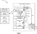
Figure 1 , there is shown a block diagram depiction of animaging system 20 according to one example embodiment.Imaging system 20 includes animage forming device 22 and acomputer 24.Image forming device 22 communicates withcomputer 24 via acommunications link 26. As used herein, the term "communications link" generally refers to any structure that facilitates electronic communication between multiple components and may operate using wired or wireless technology and may include communications over the Internet. - In the example embodiment shown in
Figure 1 ,image forming device 22 is a multifunction machine (sometimes referred to as an all-in-one (AIO) device) that includes acontroller 28, aprint engine 30, a laser scan unit (LSU) 31, atoner cartridge 100, animaging unit 200, auser interface 36, amedia feed system 38, a media input tray 39 and ascanner system 40.Image forming device 22 may communicate withcomputer 24 via a standard communication protocol, such as, for example, universal serial bus (USB), Ethernet or IEEE 802.xx.Image forming device 22 may be, for example, an electrophotographic printer/copier including anintegrated scanner system 40 or a standalone electrophotographic printer. -
Controller 28 includes a processor unit and associatedelectronic memory 29. The processor unit may include one or more integrated circuits in the form of a microprocessor or central processing unit and may include one or more Application-Specific Integrated Circuits (ASICs).Memory 29 may be any volatile or non-volatile memory or combination thereof, such as, for example, random access memory (RAM), read only memory (ROM), flash memory and/or non-volatile RAM (NVRAM).Memory 29 may be in the form of a separate memory (e.g., RAM, ROM, and/or NVRAM), a hard drive, a CD or DVD drive, or any memory device convenient for use withcontroller 28.Controller 28 may be, for example, a combined printer and scanner controller. - In the example embodiment illustrated,
controller 28 communicates withprint engine 30 via acommunications link 50.Controller 28 communicates withtoner cartridge 100 andprocessing circuitry 44 thereon via acommunications link 51.Controller 28 communicates withimaging unit 200 andprocessing circuitry 45 thereon via acommunications link 52.Controller 28 communicates withmedia feed system 38 via acommunications link 53.Controller 28 communicates withscanner system 40 via acommunications link 54.User interface 36 is communicatively coupled tocontroller 28 via acommunications link 55.Controller 28 processes print and scan data and operatesprint engine 30 during printing andscanner system 40 during scanning.Processing circuitry toner cartridge 100 andimaging unit 200, respectively. Each of processingcircuitry processing circuitry -
Computer 24, which is optional, may be, for example, a personal computer, includingelectronic memory 60, such as RAM, ROM, and/or NVRAM, aninput device 62, such as a keyboard and/or a mouse, and adisplay monitor 64.Computer 24 also includes a processor, input/output (I/O) interfaces, and may include at least one mass data storage device, such as a hard drive, a CD-ROM and/or a DVD unit (not shown).Computer 24 may also be a device capable of communicating withimage forming device 22 other than a personal computer such as, for example, a tablet computer, a smartphone, or other electronic device. - In the example embodiment illustrated,
computer 24 includes in its memory a software program including program instructions that function as an imaging driver 66, e.g., printer/scanner driver software, forimage forming device 22. Imaging driver 66 is in communication withcontroller 28 ofimage forming device 22 via communications link 26. Imaging driver 66 facilitates communication betweenimage forming device 22 andcomputer 24. One aspect of imaging driver 66 may be, for example, to provide formatted print data to image formingdevice 22, and more particularly to printengine 30, to print an image. Another aspect of imaging driver 66 may be, for example, to facilitate collection of scanned data fromscanner system 40. - In some circumstances, it may be desirable to operate
image forming device 22 in a standalone mode. In the standalone mode,image forming device 22 is capable of functioning withoutcomputer 24. Accordingly, all or a portion of imaging driver 66, or a similar driver, may be located incontroller 28 ofimage forming device 22 so as to accommodate printing and/or scanning functionality when operating in the standalone mode. -
Print engine 30 includes a laser scan unit (LSU) 31,toner cartridge 100,imaging unit 200 and afuser 37, all mounted withinimage forming device 22.Toner cartridge 100 andimaging unit 200 are removably mounted inimage forming device 22. In one embodiment,toner cartridge 100 includes a developer unit that houses a toner reservoir and a toner development system. In one embodiment, the toner development system utilizes what is commonly referred to as a single component development system. In this embodiment, the toner development system includes a toner adder roll that provides toner from the toner reservoir to a developer roll. A doctor blade provides a metered, uniform layer of toner on the surface of the developer roll. In another embodiment, the toner development system utilizes what is commonly referred to as a dual component development system. In this embodiment, toner in the toner reservoir of the developer unit is mixed with magnetic carrier beads. The magnetic carrier beads may be coated with a polymeric film to provide triboelectric properties to attract toner to the carrier beads as the toner and the magnetic carrier beads are mixed in the toner reservoir. In this embodiment, the developer unit includes a developer roll that attracts the magnetic carrier beads having toner thereon to the developer roll through the use of magnetic fields. In one embodiment,imaging unit 200 includes a photoconductor unit that houses a charge roll, a photoconductive drum and a waste toner removal system. Although the exampleimage forming device 22 illustrated inFigure 1 includes one toner cartridge and imaging unit, in the case of an image forming device configured to print in color, separate toner cartridges and imaging units may be used for each toner color. For example, in one embodiment, the image forming device includes four toner cartridges, each containing a particular toner color (e.g., black, cyan, yellow and magenta) to permit color printing, and four corresponding imaging units. - The electrophotographic printing process is well known in the art and, therefore, is described briefly herein. During a printing operation,
laser scan unit 31 creates a latent image on the photoconductive drum inimaging unit 200. Toner is transferred from the toner reservoir intoner cartridge 100 to the latent image on the photoconductive drum by the developer roll to create a toned image. The toned image is then transferred to a media sheet received byimaging unit 200 from media input tray 39 for printing. Toner may be transferred directly to the media sheet by the photoconductive drum or by an intermediate transfer member that receives the toner from the photoconductive drum. Toner remnants are removed from the photoconductive drum by the waste toner removal system. The toner image is bonded to the media sheet infuser 37 and then sent to an output location or to one or more finishing options such as a duplexer, a stapler or a hole-punch. - Referring now to
Figure 2 ,toner cartridge 100 andimaging unit 200 are shown according to one example embodiment. As discussed above,toner cartridge 100 andimaging unit 200 are each removably installed inimage forming device 22.Toner cartridge 100 is first installed on aframe 204 ofimaging unit 200 and mated withimaging unit 200.Toner cartridge 100 andimaging unit 200 are then slidably inserted together intoimage forming device 22. The arrow A shown inFigure 2 indicates the direction of insertion oftoner cartridge 100 andimaging unit 200 intoimage forming device 22. This arrangement allowstoner cartridge 100 andimaging unit 200 to be easily removed from and reinstalled inimage forming device 22 as a single unit, while permittingtoner cartridge 100 andimaging unit 200 to be repaired or replaced separately from each other. - With reference to
Figures 2-4 ,toner cartridge 100 includes ahousing 102 having an enclosed reservoir 104 (Figs. 17A and 17B ) for storing toner.Housing 102 includes a top 106, a bottom 107, first andsecond sides Front 110 ofhousing 102 leads during insertion oftoner cartridge 100 intoimage forming device 22 and rear 111 trails. In one embodiment, eachside housing 102 includes anend cap side walls main body 116 ofhousing 102. In the example embodiment illustrated,toner cartridge 100 includes arotatable developer roll 120 having arotational axis 121 that runs along a side-to-side dimension 118 ofhousing 102, fromside 108 toside 109. A portion ofdeveloper roll 120 is exposed fromhousing 102 alongfront 110 ofhousing 102, nearbottom 107 ofhousing 102 for delivering toner fromtoner cartridge 100 to a corresponding photoconductive drum ofimaging unit 200. In this manner,developer roll 120 forms an outlet for exiting toner fromtoner cartridge 100. Ahandle 122 may be provided on top 106 or rear 111 ofhousing 102 to assist with coupling anddecoupling toner cartridge 100 to and fromimaging unit 200 and insertion and removal oftoner cartridge 100 andimaging unit 200 into and out ofimage forming device 22. -
Sides respective side mating toner cartridge 100 toimaging unit 200. Alignment guides 124 are received by corresponding guide rails onimaging unit 200 that aid inpositioning toner cartridge 100 relative toimaging unit 200. In the example embodiment illustrated, analignment guide 124 is positioned on an outer side of eachend cap -
Toner cartridge 100 also includes adrive gear 126 positioned onside 108 ofhousing 102. In the embodiment illustrated,drive gear 126 mates with and receives rotational force from a corresponding drive gear onimaging unit 200 in order to provide rotational force todeveloper roll 120 and other rotatable components oftoner cartridge 100 for moving toner todeveloper roll 120 whentoner cartridge 100 is installed inimage forming device 22. In the embodiment illustrated,drive gear 126 is mounted to a shaft ofdeveloper roll 120, coaxial withdeveloper roll 120. In this embodiment, a front portion ofdrive gear 126 is exposed on thefront 110 ofhousing 102, nearbottom 107 ofhousing 102 and is unobstructed to mate with and receive rotational force from the corresponding drive gear onimaging unit 200. In the embodiment illustrated,drive gear 126 is rotatably connected to a drive train that is positioned betweenend cap 112 andside wall 114 ofhousing 102. The drive train aids in transferring rotational force fromdrive gear 126 to rotatable components oftoner cartridge 100, including, for example, to a toner adder roll that provides toner fromreservoir 104 todeveloper roll 120 and to one or more toner agitators that move toner inreservoir 104 toward the toner adder roll and that agitate and mix the toner inreservoir 104. In the example embodiment illustrated,drive gear 126 is formed as a helical gear, but other configurations may be used as desired. -
Toner cartridge 100 also includes anelectrical connector 130 positioned onside 109 ofhousing 102 that includes one or more electrical contacts 132 (Fig. 8 ) that mate with corresponding electrical contacts inimage forming device 22 whentoner cartridge 100 is installed inimage forming device 22 in order to facilitate communications link 51 betweencontroller 28 ofimage forming device 22 andprocessing circuitry 44 oftoner cartridge 100 as discussed in greater detail below. - With reference to
Figures 2 ,5 and 6 ,imaging unit 200 includes ahousing 202 including a top 206, a bottom 207, first andsecond sides Front 210 ofhousing 202 leads during insertion ofimaging unit 200 intoimage forming device 22 and rear 211 trails. In the embodiment illustrated,frame 204 includes a tonercartridge receiving area 205 positioned atrear 211 ofhousing 202. Ahandle 212 may be provided onrear 211 ofhousing 202, e.g., onframe 204, to assist with insertion and removal oftoner cartridge 100 andimaging unit 200 into and out ofimage forming device 22. - In the example embodiment illustrated,
imaging unit 200 includes a rotatablephotoconductive drum 220 having arotational axis 221 that runs along a side-to-side dimension 218 ofhousing 202, fromside 208 toside 209. A rear portion ofphotoconductive drum 220 is open to tonercartridge receiving area 205 offrame 204 for receiving toner fromdeveloper roll 120 oftoner cartridge 100. A bottom portion ofphotoconductive drum 220 is exposed fromhousing 202 onbottom 207 ofhousing 202. Toner on the outer surface ofphotoconductive drum 220 is transferred from the bottom portion of the outer surface ofphotoconductive drum 220 to a media sheet or intermediate transfer member during a print operation.Imaging unit 200 also includes arotatable charge roll 222 in contact with the outer surface ofphotoconductive drum 220 that charges the outer surface ofphotoconductive drum 220 to a predetermined voltage.Imaging unit 200 also includes a waste toner removal system that may include a cleaner blade or roll that removes residual toner from the outer surface ofphotoconductive drum 220. In the example embodiment illustrated,imaging unit 200 includes awaste toner reservoir 224 positioned at thefront 210 ofhousing 202.Waste toner reservoir 224 stores toner removed fromphotoconductive drum 220 by the cleaner blade or roll. -
Sides respective side toner cartridge 100 andimaging unit 200 into and out ofimage forming device 22. Alignment guides 226 are received by corresponding guide rails inimage forming device 22 that aid inpositioning toner cartridge 100 andimaging unit 200 relative to image formingdevice 22.Sides frame 204 may each include aguide rail 228 that receives acorresponding alignment guide 124 oftoner cartridge 100 to aid inpositioning toner cartridge 100 relative toimaging unit 200. -
Imaging unit 200 also includes adrive coupler 230 positioned onside 208 ofhousing 202.Drive coupler 230 mates with and receives rotational force from a corresponding drive coupler inimage forming device 22 in order to provide rotational force tophotoconductive drum 220 when imagingunit 200 is installed inimage forming device 22. In the embodiment illustrated,drive coupler 230 is positioned at an axial end ofphotoconductive drum 220, coaxial withphotoconductive drum 220. In this embodiment, an outer axial end ofdrive coupler 230 is exposed onside 208 ofhousing 202 and is unobstructed to mate with and receive rotational force from the corresponding drive coupler inimage forming device 22. In the example embodiment illustrated,drive coupler 230 is configured to receive rotational force at the outer axial end ofdrive coupler 230, but other configurations may be used as desired. In some embodiments,charge roll 222 is driven by friction contact between the surfaces ofcharge roll 222 andphotoconductive drum 220. In other embodiments,charge roll 222 is connected to drivecoupler 230 by one or more gears. - In the embodiment illustrated,
imaging unit 200 also includes adrive gear 232 attached tophotoconductive drum 220, axially inboard ofdrive coupler 230. A portion ofdrive gear 232 is exposed to tonercartridge receiving area 205 offrame 204 permittingdrive gear 126 oftoner cartridge 100 to mate withdrive gear 232 ofimaging unit 200 whentoner cartridge 100 is installed onframe 204 ofimaging unit 200 to permit the transfer of rotational force received bydrive coupler 230 ofimaging unit 200 to drivegear 126 oftoner cartridge 100 by way ofdrive gear 232 ofimaging unit 200. -
Imaging unit 200 also includes anelectrical connector 240 positioned on a portion offrame 204 onside 209 ofhousing 202 that includes one or moreelectrical contacts 242 that mate with corresponding electrical contacts inimage forming device 22 when imagingunit 200 is installed inimage forming device 22 in order to facilitate communications link 52 betweencontroller 28 ofimage forming device 22 andprocessing circuitry 45 ofimaging unit 200 as discussed in greater detail below. -
Figures 7-9 showelectrical connector 130 oftoner cartridge 100 in greater detail. In the example embodiment illustrated,electrical connector 130 is positioned onside 109 of housing, nearbottom 107 and rear 111 ofhousing 102.Electrical connector 130 is movably connected tohousing 102 such thatelectrical connector 130 is movable relative tohousing 102 between a retracted or home position shown inFigure 7 and an operative position shown inFigure 8 . In the example embodiment illustrated,electrical connector 130 is pivotable about apivot axis 134 relative tohousing 102 between the retracted position and the operative position. In the example embodiment illustrated,pivot axis 134 extends in a direction from rear 111 tofront 110 and angles downward from rear 111 tofront 110, butpivot axis 134 may take other orientations as desired. In the example embodiment illustrated,pivot axis 134 is positioned along aproximal end 131a ofelectrical connector 130 relative toside 109 ofhousing 102 andreservoir 104 along side-to-side dimension 118 ofhousing 102. In some embodiments,electrical connector 130 is biased toward the retracted position by a biasingmember 136. In the example embodiment illustrated, biasingmember 136 includes a torsion spring; however, any suitable biasingmember 136 may be used as desired, such as, for example, one or more compression springs, extension springs, leaf springs or a material having resilient properties. - In the embodiment illustrated,
electrical connector 130 includes a printedcircuit board 138 havingelectrical contacts 132 andprocessing circuitry 44 positioned thereon. Printedcircuit board 138 may be attached by a suitable fastener or adhesive as desired.Electrical contacts 132 are positioned on aface 140 of printedcircuit board 138. In the example embodiment illustrated, in the retracted position ofelectrical connector 130 shown inFigure 7 , face 140 of printedcircuit board 138 includingelectrical contacts 132 faces downward, towardbottom 107 ofhousing 102, and inward, towardside 109 ofhousing 102. In addition to facing downward and inward, in the embodiment illustrated, face 140 of printedcircuit board 138 includingelectrical contacts 132 also faces rearward, towardrear 111 ofhousing 102, when electrical connector is in its retracted position due to the angle ofpivot axis 134. In the operative position ofelectrical connector 130 shown inFigure 8 , face 140 of printedcircuit board 138 includingelectrical contacts 132 faces downward, towardbottom 107 ofhousing 102, such as, for example, primarily downward. In addition to facing downward, in the embodiment illustrated, face 140 of printedcircuit board 138 includingelectrical contacts 132 also faces rearward, towardrear 111 ofhousing 102, due to the angle ofpivot axis 134 and slightly outward, away fromside 109 ofhousing 102, when electrical connector is in its operative position.Electrical contacts 132 are positioned along adistal end 131b ofelectrical connector 130 relative toside 109 ofhousing 102 andreservoir 104 along side-to-side dimension 118 ofhousing 102, which also forms a free end ofelectrical connector 130 relative to pivotaxis 134 in the embodiment illustrated, whenelectrical connector 130 is in its operative position. - Accordingly, in this embodiment, when
electrical connector 130 moves from its retracted position to its operative position,electrical connector 130 pivots upward relative tohousing 102 aboutpivot axis 134 withface 140 of printedcircuit board 138 includingelectrical contacts 132 swinging upward and outward, away fromside 109, aboutpivot axis 134. This movement is reversed whenelectrical connector 130 moves from its operative position to its retracted position whereinelectrical connector 130 pivots downward relative tohousing 102 aboutpivot axis 134 withface 140 of printedcircuit board 138 includingelectrical contacts 132 swinging downward and inward, towardside 109, aboutpivot axis 134. In the example embodiment illustrated, whenelectrical connector 130 is in its operative position withface 140 of printedcircuit board 138 facing downward,electrical contacts 132 are exposed fromhousing 102 and unobstructed from below permitting corresponding electrical contacts inimage forming device 22 to contact and mate withelectrical contacts 132 ofelectrical connector 130 from below. In this embodiment, whenelectrical connector 130 is in its retracted position with printedcircuit board 138 swung downward and inward, towardside 109,electrical contacts 132 are partially hidden from view in order to help protectelectrical contacts 132 and printedcircuit board 138 from contamination, electrostatic discharge and physical damage. -
Electrical connector 130 includes anactuation member 142 that is positioned to receive a force to overcome the bias applied toelectrical connector 130 by biasingmember 136 in order to moveelectrical connector 130 from its retracted position to its operative position. In the embodiment illustrated,actuation member 142 includes acam surface 144 alongdistal end 131b ofelectrical connector 130 that extends forward, towardfront 110 ofhousing 102, from afront end 131c ofelectrical connector 130 that is proximate tofront 110 ofhousing 102.Cam surface 144 includes abottom portion 144a that faces downward, towardbottom 107 ofhousing 102, whenelectrical connector 130 is in its operative position and anouter side portion 144b that faces outward, away fromside 109 ofhousing 102, whenelectrical connector 130 is in its operative position. In the embodiment illustrated,bottom portion 144a ofcam surface 144 angles upward relative to face 140 of printedcircuit board 138, away fromface 140 of printedcircuit board 138 andelectrical contacts 132, in a direction from rear 111 tofront 110 ofhousing 102 andouter side portion 144b ofcam surface 144 angles inward, towardpivot axis 134, in a direction from rear 111 tofront 110 ofhousing 102. - While the example embodiment illustrated includes
electrical contacts 132 positioned on printedcircuit board 138 havingprocessing circuitry 44, in other embodiments, printedcircuit board 138 havingprocessing circuitry 44 is positioned elsewhere onhousing 102 andelectrical contacts 132 are disposed onelectrical connector 130 in the positions illustrated and are connected to processingcircuitry 44 by suitable traces, wires or the like. -
Figures 10 and 11 showelectrical connector 240 ofimaging unit 200 in greater detail. In this embodiment,frame 204 ofimaging unit 200 includes aside wall 234 onside 208 ofhousing 202, aside wall 235 onside 209 ofhousing 202 and arear wall 236 on rear 211 of housing 202 (Figs. 5 and 6 ). In this embodiment,electrical connector 240 includes a printedcircuit board 244 positioned on amount 246 onside wall 235 offrame 204. Printedcircuit board 244 may be attached by a suitable fastener or adhesive as desired.Processing circuitry 45 ofimaging unit 200 is positioned on printedcircuit board 244.Mount 246 includes abottom surface 248 and afront wall 249 and arear wall 250 that extend upward frombottom surface 248 and along side-to-side dimension 218. In the embodiment illustrated, printedcircuit board 244 is positioned onbottom surface 248 ofmount 246 betweenfront wall 249 andrear wall 250 ofmount 246. In this embodiment,electrical contacts 242 are positioned on atop face 252 of printedcircuit board 244 such thatelectrical contacts 242 face upward, towardtop 206 ofhousing 202. Printedcircuit board 244 and mount 246 are positioned adjacent to anopening 254 that extends throughside wall 235 offrame 204 at an outer side ofmount 246 and that permits corresponding electrical contacts inimage forming device 22 to access and mate withelectrical contacts 242 ofelectrical connector 240 ofimaging unit 200 andelectrical contacts 132 ofelectrical connector 130 oftoner cartridge 100 fromside 209 ofhousing 202 ofimaging unit 200 andside 109 ofhousing 102 oftoner cartridge 100 as discussed in greater detail below. - In the embodiment illustrated,
front wall 249 ofmount 246 includes an actuation member such as acam surface 256 on a top edge offront wall 249 thatcontacts cam surface 144 ofelectrical connector 130 oftoner cartridge 100 whentoner cartridge 100 is installed onframe 204 ofimaging unit 200 in order to moveelectrical connector 130 oftoner cartridge 100 from its retracted position to its operative position as discussed in greater detail below. In this embodiment,cam surface 256 angles upward in a direction fromside 208 toside 209 ofhousing 202. In the embodiment illustrated, anupstop 258 is spaced abovecam surface 256 along a top edge ofopening 254.Upstop 258 is positioned to limit the travel ofelectrical connector 130 oftoner cartridge 100 from its retracted position to its operative position as discussed in greater detail below. - While the example embodiment illustrated includes
electrical contacts 242 positioned on printedcircuit board 244 havingprocessing circuitry 45, in other embodiments, printedcircuit board 244 havingprocessing circuitry 45 is positioned elsewhere onhousing 202 andelectrical contacts 242 are disposed onelectrical connector 240, e.g., onmount 246, in the positions illustrated and are connected to processingcircuitry 45 by suitable traces, wires or the like. -
Figures 12A-12C are sequential views that show the actuation ofelectrical connector 130 oftoner cartridge 100 from its retracted position to its operative position during the installation oftoner cartridge 100 ontoframe 204 ofimaging unit 200. In the example embodiment illustrated, engagement between alignment guides 124 oftoner cartridge 100 andguide rails 228 ofimaging unit 200 controls the positioning oftoner cartridge 100 relative toimaging unit 200 during installation oftoner cartridge 100 ontoframe 204 ofimaging unit 200. In this embodiment,toner cartridge 100 pivots counterclockwise as viewed inFigures 12A-12C about a pivot axis that runs fromalignment guide 124 onside 108 ofhousing 102 toalignment guide 124 onside 109 ofhousing 102 during installation oftoner cartridge 100 ontoframe 204 ofimaging unit 200. -
Figure 12A showstoner cartridge 100 as it lowers intoframe 204 ofimaging unit 200 withelectrical connector 130 oftoner cartridge 100 in its retracted position ascam surface 144 ofactuation member 142 ofelectrical connector 130 begins to contactcam surface 256 onfront wall 249 ofmount 246 ofimaging unit 200. The contact betweencam surface 144 ofelectrical connector 130 andcam surface 256 ofimaging unit 200 astoner cartridge 100 lowers intoframe 204 ofimaging unit 200 overcomes the bias force applied toelectrical connector 130 by biasingmember 136 and causeselectrical connector 130 to swing (out of the page as viewed inFigures 12A-12C ) aboutpivot axis 134 from its retracted position toward its operative position. Astoner cartridge 100 continues to lower intoframe 204 ofimaging unit 200,cam surface 144 ofelectrical connector 130 travels up the angled portion ofcam surface 256 ofimaging unit 200 causingelectrical connector 130 to continue to pivot aboutpivot axis 134 from its retracted position toward its operative position.Figure 12B showselectrical connector 130 oftoner cartridge 100 in an intermediate position between the retracted position and the operative position astoner cartridge 100 lowers intoframe 204 ofimaging unit 200. Whentoner cartridge 100 reaches its final, installed position relative toimaging unit 200, contact betweencam surface 144 ofelectrical connector 130 andcam surface 256 ofimaging unit 200 holdselectrical connector 130 oftoner cartridge 100 in its operative position withelectrical contacts 132 ofelectrical connector 130 facing downward. -
Figure 12C showstoner cartridge 100 fully installed onframe 204 ofimaging unit 200 withelectrical connector 130 in its operative position. Whentoner cartridge 100 is in its final position relative toimaging unit 200,electrical contacts 132 oftoner cartridge 100 andelectrical contacts 242 ofimaging unit 200 are exposed to an exterior ofimaging unit 200 throughopening 254 inside wall 235 offrame 204 permitting an electrical connector inimage forming device 22 to enteropening 254 and mate withelectrical contacts 132 oftoner cartridge 100 andelectrical contacts 242 ofimaging unit 200 whentoner cartridge 100 andimaging unit 200 are installed inimage forming device 22. In this embodiment, whentoner cartridge 100 is in its final position relative toimaging unit 200 withelectrical connector 130 oftoner cartridge 100 in its operative position,electrical contacts 132 oftoner cartridge 100 face downward andelectrical contacts 242 ofimaging unit 200 face upward such thatelectrical contacts 132 oftoner cartridge 100 andelectrical contacts 242 ofimaging unit 200 face each other in a spaced relationship with avertical gap 300 positioned betweenelectrical contacts 132 oftoner cartridge 100 andelectrical contacts 242 ofimaging unit 200. -
Figure 13 showstoner cartridge 100 installed onimaging unit 200 withtoner cartridge 100 andimaging unit 200 installed inimage forming device 22 and anelectrical connector 302 ofimage forming device 22 positioned in a disengaged position relative totoner cartridge 100 andimaging unit 200. A frame ofimage forming device 22 thatelectrical connector 302 is mounted to and extends from is omitted in order to more clearly illustrate the positional relationship betweenelectrical connector 302 andtoner cartridge 100 andimaging unit 200. In this embodiment,electrical connector 302 is spaced outward sideways away fromsides toner cartridge 100 andimaging unit 200 whenelectrical connector 302 is in the disengaged position.Electrical connector 302 ofimage forming device 22 includeselectrical contacts 304 on a top portion thereof andelectrical contacts 306 on a bottom portion thereof.Electrical contacts 304 are positioned to contactelectrical contacts 132 oftoner cartridge 100 to facilitate communications link 51 betweencontroller 28 ofimage forming device 22 andprocessing circuitry 44 oftoner cartridge 100 whenelectrical connector 302 moves from the disengaged position to an engaged position aftertoner cartridge 100 andimaging unit 200 are installed inimage forming device 22. Similarly,electrical contacts 306 are positioned to contactelectrical contacts 242 ofimaging unit 200 to facilitate communications link 52 betweencontroller 28 ofimage forming device 22 andprocessing circuitry 45 ofimaging unit 200 whenelectrical connector 302 moves from the disengaged position to the engaged position aftertoner cartridge 100 andimaging unit 200 are installed inimage forming device 22. In one embodiment,electrical connector 302 is operatively connected to an access door of image forming device that permits user access totoner cartridge 100 andimaging unit 200 withinimage forming device 22 such that the closing of the access door moveselectrical connector 302 from its disengaged position to its engaged position and the opening of the access door moveselectrical connector 302 from its engaged position to its disengaged position. In other embodiments, a motor, solenoid or the like of theimage forming device 22 selectively moveselectrical connector 302 between the disengaged position and the engaged position. -
Figure 14 showstoner cartridge 100 installed onimaging unit 200 withtoner cartridge 100 andimaging unit 200 installed inimage forming device 22 andelectrical connector 302 ofimage forming device 22 positioned in an engaged position relative totoner cartridge 100 andimaging unit 200. Once again, the frame ofimage forming device 22 thatelectrical connector 302 is mounted to is omitted for clarity. Aftertoner cartridge 100 andimaging unit 200 are mated with each other and installed inimage forming device 22,electrical connector 302 moves from the disengaged position to the engaged position. In the embodiment illustrated,electrical connector 302 translates along side-to-side dimension 118 ofhousing 102 towardtoner cartridge 100 andimaging unit 200 whenelectrical connector 302 moves from the disengaged position to the engaged position. Aselectrical connector 302 advances towardtoner cartridge 100 andimaging unit 200,electrical connector 302 passes through opening 254 offrame 204 ofimaging unit 200 and entersvertical gap 300 betweenelectrical contacts 132 oftoner cartridge 100 andelectrical contacts 242 ofimaging unit 200. In the embodiment illustrated,electrical contacts electrical connector 302 are configured to spring outward (clockwise and counterclockwise, respectively, as viewed inFigure 14 ) into contact withelectrical contacts 132 oftoner cartridge 100 andelectrical contacts 242 ofimaging unit 200, respectively, aselectrical connector 302 reaches the engaged position.Electrical contacts electrical connector 302 are also deflectable and sized to have an interference fit withelectrical contacts 132 oftoner cartridge 100 andelectrical contacts 242 ofimaging unit 200, respectively, whenelectrical connector 302 reaches the engaged position in order to maintain consistent, reliable electrical contact betweenelectrical contacts electrical connector 302 andelectrical contacts 132 oftoner cartridge 100 andelectrical contacts 242 ofimaging unit 200. -
Figure 15 showselectrical connector 302 in the engaged position passing throughopening 254 ofimaging unit 200 withelectrical contacts electrical connector 302 in contact withelectrical contacts 132 oftoner cartridge 100 andelectrical contacts 242 ofimaging unit 200. In the embodiment illustrated, the upward force applied toelectrical connector 130 oftoner cartridge 100 byelectrical contacts 304 ofelectrical connector 302 ofimage forming device 22 pushes an upper surface ofelectrical connector 130 againstupstop 258 ofimaging unit 200 in order to limit the upward movement ofelectrical connector 130. In this embodiment, the upward force applied toelectrical contacts 132 oftoner cartridge 100 byelectrical contacts 304 ofelectrical connector 302 ofimage forming device 22 is equal and opposite to the downward force applied toelectrical contacts 242 ofimaging unit 200 byelectrical contacts 306 ofelectrical connector 302 ofimage forming device 22. Contact betweenupstop 258 ofimaging unit 200 and the upper surface ofelectrical connector 130 oftoner cartridge 100 results in a downward reaction force on the upper surface ofelectrical connector 130 oftoner cartridge 100 that aids in keeping most of the force fromelectrical connector 302 onimaging unit 200, which is firmly positioned inimage forming device 22 after installation, instead of ontoner cartridge 100. If, instead, upstop 258 ofimaging unit 200 was omitted, the upward force onelectrical connector 130 oftoner cartridge 100 could tend to lifttoner cartridge 100 upward relative toimaging unit 200, in turn, reducing the nip force betweendeveloper roll 120 andphotoconductive drum 220, which could cause print defects. - When
electrical connector 302 ofimage forming device 22 moves from the engaged position to the disengaged position, such as upon the opening of the access door ofimage forming device 22, the motion ofelectrical connector 302 is reversed such thatelectrical connector 302 passes out ofopening 254 and moves away fromtoner cartridge 100 andimaging unit 200, returning to the position shown inFigure 13 . In the embodiment illustrated,electrical contacts electrical connector 302 return inward (counterclockwise and clockwise, respectively, as viewed inFigure 14 ) aselectrical connector 302 moves from the engaged position to the disengaged position. - With reference to
Figure 16 , in some embodiments,electrical connector 130 oftoner cartridge 100 also includes amagnetic sensor 150 positioned on printedcircuit board 138 for detecting one or more magnets movably positioned inreservoir 104 oftoner cartridge 100.Magnetic sensor 150 may be any suitable device capable of detecting the presence or absence of a magnetic field. For example,magnetic sensor 150 may be a Hall-effect sensor, which is a transducer that varies its electrical output in response to a magnetic field. In the embodiment illustrated,magnetic sensor 150 is positioned on aface 141 of printedcircuit board 138 that isopposite face 140 of printedcircuit board 138 that includeselectrical contacts 132. In this embodiment,magnetic sensor 150 is positioned alongproximal end 131a ofelectrical connector 130, proximate toreservoir 104, e.g., in line withpivot axis 134 ofelectrical connector 130. In the embodiment illustrated,magnetic sensor 150 is positioned orthogonal to face 141 of printedcircuit board 138 so that asensing axis 152 ofmagnetic sensor 150 is oriented parallel to face 141 of printedcircuit board 138. In this orientation, sensingaxis 152 ofmagnetic sensor 150 is generally parallel to side-to-side dimension 118 ofhousing 102 whenelectrical connector 130 is in the operative position. In the embodiment illustrated,magnetic sensor 150 is electrically connected, e.g., via one or more traces on printedcircuit board 138, to one of theelectrical contacts 132 on printedcircuit board 138 for transmitting an output ofmagnetic sensor 150 tocontroller 28 ofimage forming device 22 via communications link 51. -
Figures 17A and 17B show toner cartridge 100 with a portion offront 110 ofhousing 102 omitted and withside wall 115 omitted in order to show the positional relationship betweenmagnetic sensor 150 and various features inreservoir 104 according to one example embodiment.Figure 17A showselectrical connector 130 in the operative position andFigure 17B showselectrical connector 130 in the retracted position. In the example embodiment illustrated,toner cartridge 100 includes atoner agitator assembly 160 rotatably mounted inreservoir 104.Toner agitator assembly 160 includes adrive shaft 162 rotatably positioned inreservoir 104 that extends through aligned openings inside walls shaft 162 is operatively connected to drivegear 126 to receive rotational force fromdrive gear 126. For example, a drive gear that mates (directly or indirectly by one or more intermediate gears) withdrive gear 126 may be provided on an end ofdrive shaft 162. -
Toner agitator assembly 160 includes one ormore toner agitators 164 that extend outward fromdrive shaft 162 for mixing toner inreservoir 104 and for moving toner toward the toner adder roll oftoner cartridge 100.Toner agitators 164 may take many different shapes and configurations depending on the architecture oftoner cartridge 100 including, such as, for example, any suitable combination of one or more paddles, augers, rakes, combs, scoops, plows, arms, extensions, prongs, flaps, mixers, conveyors, screws, etc. - In the embodiment illustrated,
toner agitator assembly 160 includes at least onepermanent magnet 166 that moves withinreservoir 104 in response to the rotation ofdrive shaft 162 andtoner agitator assembly 160. In some embodiments, the movement of magnet(s) 166 during rotation ofdrive shaft 162 as sensed bymagnetic sensor 150 provides an indication of the amount of toner present inreservoir 104. For example, magnet(s) may be positioned in one of the orientations described in United States Patent No.8,989,611 , entitled "Replaceable Unit for an Image Forming Device Having a Falling Paddle for Toner Level Sensing," United States Patent No.9,389,582 9,519,243 toner cartridge 100, such as, for example, toner cartridge type, toner color, toner capacity, geographic region of manufacture or use, etc. In the embodiment illustrated, magnet(s) 166 are positioned at an axial end ofreservoir 104 proximate toside wall 115. - As shown in
Figure 17A , whenelectrical connector 130 oftoner cartridge 100 is in the operative position, sensingaxis 152 ofmagnetic sensor 150 is generally parallel to side-to-side dimension 118 ofhousing 102 and to driveshaft 162 such thatmagnetic sensor 150 is oriented to detect the magnetic field(s) of magnet(s) 166 throughside wall 115 as magnet(s) 166 passmagnetic sensor 150. As shown inFigure 17B , whenelectrical connector 130 oftoner cartridge 100 is in the retracted position,magnetic sensor 150 is angled upward relative to side-to-side dimension 118 ofhousing 102 and to driveshaft 162. As a result, in some embodiments,magnetic sensor 150 is out of alignment with magnet(s) 166 whenelectrical connector 130 is in the retracted position and may not sense magnet(s) 166 as magnet(s) 166 passmagnetic sensor 150. Accordingly, in the embodiment illustrated, the movement ofelectrical connector 130 oftoner cartridge 100 from the retracted position to the operative position upon the installation oftoner cartridge 100 onimaging unit 200 movesmagnetic sensor 150 from a misaligned position relative to magnet(s) 166 to an aligned position relative to magnet(s) 166. - It will be appreciated that the configuration of
electrical connector 130 oftoner cartridge 100 including the motion ofelectrical connector 130 between the retracted position and the operative position is not limited to the example embodiment illustrated. For example, the embodiment illustrated includes anelectrical connector 130 that pivots between the retracted position and the operative position about a fixedpivot axis 134. However, in other embodiments, the location of the pivot axis of the electrical connector of the toner cartridge moves relative to the housing of the toner cartridge as the electrical connector of the toner cartridge pivots between the retracted position and the operative position. - Further, the embodiment illustrated includes a rigid
electrical connector 130 includingelectrical contacts 132 positioned on a rigid printedcircuit board 138. However, in other embodiments, the electrical contacts of the electrical connector of the toner cartridge are flexible relative to the housing of the toner cartridge permitting the electrical contacts to flex between the retracted position and the operative position. For example, the electrical contacts of the electrical connector of the toner cartridge may be formed on a flexible printed circuit board or the electrical contacts may be electrically connected to a printed circuit board mounted elsewhere on the housing of the toner cartridge and positioned on or connected to a flexible substrate other than the printed circuit board. - Further, while the embodiment illustrated includes an
electrical connector 130 oftoner cartridge 100 that pivots between the retracted position and the operative position, it will be appreciated that the electrical connector of the toner cartridge may move in other manners relative to the housing of the toner cartridge between the retracted position and the operative position, such as, for example, translating between the retracted position and the operative position. For example,Figure 18 shows atoner cartridge 1100 having anelectrical connector 1130 positioned on aside 1109 of ahousing 1102.Electrical connector 1130 translates outward sideways (away from side 1109) aselectrical connector 1130 travels from the retracted position to the operative position and inward sideways (toward side 1109) aselectrical connector 1130 travels from the operative position to the retracted position. In the embodiment illustrated,electrical connector 1130 translates parallel to a side-to-side dimension 1118 ofhousing 1102. In other embodiments,electrical connector 1130 translates at an angle to side-to-side dimension 1118 ofhousing 1102, e.g., upward, downward, rearward and/or frontward. In the example embodiment illustrated, the movement ofelectrical connector 1130 between the retracted position and the operative position is controlled by engagement between apost 1170 extending fromelectrical connector 1130 and anelongated slot 1172 onhousing 1102. However, this configuration may be reversed or other configurations may be used as desired. In the example embodiment illustrated,electrical connector 1130 includes anactuation member 1142 having a cam surface 1144 that contacts a corresponding actuation member on the imaging unit during the installation oftoner cartridge 1100 onto the imaging unit to moveelectrical connector 130 from the retracted position to the operative position. - It will also be appreciated that
imaging unit 200 may include one or more actuation or cam features modified relative tocam surface 256 of the example embodiment illustrated as desired in order to actuate the electrical connector of the toner cartridge from the retracted position to the operative position during installation of the toner cartridge onto the imaging unit. Alternatively, the electrical connector of the toner cartridge may be actuated by other means, such as, for example, by a linkage actuated by the opening and closing of the access door of the image forming device or by a user-actuated mechanism. - While the example embodiment illustrated includes a
magnetic sensor 150 positioned on anelectrical connector 130 that moves between a retracted position and an operative position, in other embodiments including a magnetic sensor, either or both ofmagnetic sensor 150 and electrical contact(s) 132 may be fixedly positioned onhousing 102 oftoner cartridge 100 as desired. - While the example embodiment illustrated includes
toner cartridge 100 having a movableelectrical connector 130 andimaging unit 200 having an actuation member that moveselectrical connector 130 from its retracted position to its operative position during installation oftoner cartridge 100 ontoimaging unit 200, this configuration may be reversed as desired such that the imaging unit includes a movable electrical connector and the toner cartridge includes an actuation member that moves the electrical connector from a retracted position to an operative position during mating of the toner cartridge with the imaging unit. - Although the example embodiment discussed above includes a pair of replaceable units in the form of a
toner cartridge 100 that includes the main toner supply for the image forming device and the developer unit and animaging unit 200 that includes the photoconductor unit for each toner color, it will be appreciated that the replaceable unit(s) of the image forming device may employ any suitable configuration as desired. For example, in one embodiment, the main toner supply for the image forming device is provided in a first replaceable unit and the developer unit and photoconductor unit are provided in a second replaceable unit. In another embodiment, the main toner supply for the image forming device, the developer unit and the photoconductor unit are provided in a single replaceable unit. Other configurations may be used as desired. - Further, it will be appreciated that the architecture and shape of
toner cartridge 100 andimaging unit 200 illustrated inFigures 2-6 is merely intended to serve as an example. Those skilled in the art understand that toner cartridges, and other toner containers, may take many different shapes and configurations. - The foregoing description illustrates various aspects of the present disclosure. It is not intended to be exhaustive. Rather, it is chosen to illustrate the principles of the present disclosure and its practical application to enable one of ordinary skill in the art to utilize the present disclosure, including its various modifications that naturally follow. All modifications and variations are contemplated within the scope of the present disclosure as determined by the appended claims. Relatively apparent modifications include combining one or more features of various embodiments with features of other embodiments.
Claims (14)
- A replaceable unit for an electrophotographic image forming device, comprising:a housing having a top, a bottom, a front and a rear positioned between a first side and a second side of the housing, the housing has a reservoir for holding toner; andan electrical connector on the first side of the housing, the electrical connector includes an electrical contact for contacting a corresponding electrical contact in the image forming device, the electrical contact of the replaceable unit is electrically connected to processing circuitry mounted on the replaceable unit, the electrical connector is movable between a first position and a second position, the electrical contact of the replaceable unit moves outward from the first side of the housing along a side-to-side dimension of the housing when the electrical connector moves from the first position to the second position such that the electrical contact of the replaceable unit is positioned further outward along the side-to-side dimension of the housing when the electrical connector is in the second position than when the electrical connector is in the first position, the electrical contact of the replaceable unit faces downward and is unobstructed from below when the electrical connector is in the second position permitting the corresponding electrical contact in the image forming device to contact the electrical contact of the replaceable unit from below.
- The replaceable unit of claim 1,
wherein the electrical connector is pivotable about a pivot axis between the first position and the second position, the electrical contact of the replaceable unit pivots outward from the first side of the housing when the electrical connector pivots from the first position to the second position. - The replaceable unit of claim 2,
wherein a position of the pivot axis is fixed relative to the housing. - The replaceable unit of claim 2 or claim 3,
wherein the pivot axis extends in a direction from the rear of the housing to the front of the housing and angles downward in the direction from the rear of the housing to the front of the housing. - The replaceable unit of any one of claims 2 to 4,
wherein the electrical contact of the replaceable unit pivots upward when the electrical connector pivots from the first position to the second position. - The replaceable unit of any one of the preceding claims,
further comprising a developer roll rotatably positioned on the housing, a portion of an outer surface of the developer roll is exposed along the front of the housing for supplying toner from the reservoir to a corresponding photoconductive drum. - The replaceable unit of any one of the preceding claims,
further comprising an interface gear on the second side of the housing, at least a portion of the interface gear is exposed on the front of the housing for mating with a corresponding drive gear and receiving rotational force from the corresponding drive gear. - The replaceable unit of any one of the preceding claims,
further comprising a biasing member that biases the electrical connector toward the first position. - The replaceable unit of any one of the preceding claims,
wherein when the electrical connector is in the second position, the electrical contact of the replaceable unit is positioned closer to the bottom of the housing than to the top of the housing and the electrical contact of the replaceable unit is positioned closer to the rear of the housing than to the front of the housing. - The replaceable unit of any one of the preceding claims,
wherein the electrical contact of the replaceable unit faces inward toward the first side of the housing when the electrical connector is in the first position. - The replaceable unit of any one of the preceding claims,
wherein the electrical connector includes a printed circuit board that includes the processing circuitry, the electrical contact of the replaceable unit is positioned on a face of the printed circuit board, the face of the printed circuit board faces downward when the electrical connector is in the second position and the face of the printed circuit board faces inward toward the first side of the housing when the electrical connector is in the first position. - The replaceable unit of any one of the preceding claims,
wherein the electrical connector includes a cam surface that is positioned along a distal end of the electrical connector relative to the first side of the housing for contacting an actuation member during installation of the replaceable unit to move the electrical connector from the first position to the second position. - The replaceable unit of claim 12,
wherein the cam surface extends toward the front of the housing from a front portion of the electrical connector, a bottom portion of the cam surface faces downward when the electrical connector is in the second position, the bottom portion of the cam surface angles upward in a direction from the rear of the housing to the front of the housing when the electrical connector is in the second position. - The replaceable unit of claim 12,
wherein the cam surface extends toward the front of the housing from a front portion of the electrical connector, an outer side portion of the cam surface faces outward away from the first side of the housing when the electrical connector is in the second position, the outer side portion of the cam surface angles inward toward the first side of the housing in a direction from the rear of the housing to the front of the housing when the electrical connector is in the second position.
Applications Claiming Priority (1)
| Application Number | Priority Date | Filing Date | Title |
|---|---|---|---|
| US16/382,759 US10761476B1 (en) | 2019-04-12 | 2019-04-12 | Replaceable unit for an electrophotographic image forming device having a movable electrical connector |
Publications (1)
| Publication Number | Publication Date |
|---|---|
| EP3722881A1 true EP3722881A1 (en) | 2020-10-14 |
Family
ID=70189807
Family Applications (1)
| Application Number | Title | Priority Date | Filing Date |
|---|---|---|---|
| EP20168128.5A Pending EP3722881A1 (en) | 2019-04-12 | 2020-04-06 | Replaceable unit for an electrophotographic image forming device having a movable electrical connector |
Country Status (8)
| Country | Link |
|---|---|
| US (4) | US10761476B1 (en) |
| EP (1) | EP3722881A1 (en) |
| CN (1) | CN113646701A (en) |
| AU (1) | AU2020271533A1 (en) |
| BR (1) | BR112021018278A2 (en) |
| CA (1) | CA3136349A1 (en) |
| MX (1) | MX2021012010A (en) |
| WO (1) | WO2020210564A2 (en) |
Families Citing this family (5)
| Publication number | Priority date | Publication date | Assignee | Title |
|---|---|---|---|---|
| JP7305417B2 (en) * | 2019-04-25 | 2023-07-10 | キヤノン株式会社 | Process cartridge and image forming apparatus |
| USD952030S1 (en) * | 2019-10-23 | 2022-05-17 | Lexmark International, Inc. | Toner cartridge |
| US11493876B2 (en) | 2020-04-24 | 2022-11-08 | Lexmark International, Inc. | Electrical connector assembly for an image forming device |
| KR20230172655A (en) * | 2022-06-15 | 2023-12-26 | 휴렛-팩커드 디벨롭먼트 컴퍼니, 엘.피. | structure for electric contact portion of toner cartridge |
| US11829085B1 (en) | 2022-08-24 | 2023-11-28 | Lexmark International, Inc. | Toner container having an angled electrical connector |
Citations (7)
| Publication number | Priority date | Publication date | Assignee | Title |
|---|---|---|---|---|
| US8989611B2 (en) | 2012-12-18 | 2015-03-24 | Lexmark International, Inc. | Replaceable unit for an image forming device having a falling paddle for toner level sensing |
| US9389582B2 (en) | 2014-06-02 | 2016-07-12 | Lexmark International, Inc. | Replaceable unit for an image forming device having magnets of varying angular offset for toner level sensing |
| EP3060962A1 (en) * | 2014-03-12 | 2016-08-31 | Samsung Electronics Co., Ltd. | Cartridge and electrophotographic image forming apparatus using the same |
| US9519243B2 (en) | 2014-06-02 | 2016-12-13 | Lexmark International, Inc. | Replaceable unit for an image forming device having magnets of varying angular offset for toner level sensing |
| EP3182210A1 (en) * | 2015-12-14 | 2017-06-21 | Lexmark International, Inc. | Replaceable unit for an electrophotographic image forming device having a retractable electrical connector |
| EP3287851A1 (en) * | 2016-08-22 | 2018-02-28 | Brother Kogyo Kabushiki Kaisha | Developing cartridge and image forming apparatus including the same |
| EP3301515A1 (en) * | 2016-09-30 | 2018-04-04 | Brother Kogyo Kabushiki Kaisha | Developing cartridge |
Family Cites Families (114)
| Publication number | Priority date | Publication date | Assignee | Title |
|---|---|---|---|---|
| US4839691A (en) | 1986-03-31 | 1989-06-13 | Kabushiki Kaisha Toshiba | Image forming apparatus |
| DE3716152A1 (en) | 1987-05-14 | 1988-11-24 | Standard Elektrik Lorenz Ag | FLOORING CONNECTOR FITTED ON A MOUNTING PLATE |
| US4912563A (en) * | 1987-07-04 | 1990-03-27 | Ricoh Company, Ltd. | Electrophotographic image forming apparatus having replaceable optical unit |
| US4891017A (en) | 1988-04-26 | 1990-01-02 | Amp Incorporated | Socket connector with pin aligning housing |
| US5121165A (en) | 1988-10-28 | 1992-06-09 | Mita Industrial Co., Ltd. | Developer unit and a toner hopper for an image forming device |
| JPH066377Y2 (en) | 1989-10-25 | 1994-02-16 | ブラザー工業株式会社 | Photoconductor cartridge |
| US5002497A (en) | 1990-01-26 | 1991-03-26 | Molex Incorporated | Floatable panel mountable electrical connector assembly |
| JP2568142B2 (en) | 1991-12-30 | 1996-12-25 | モレックス インコーポレーテッド | Floating structure electrical connector and manufacturing method thereof |
| NL9200884A (en) | 1992-05-20 | 1993-12-16 | Framatome Connectors Belgium | CONNECTOR ASSEMBLY. |
| JP3044997B2 (en) | 1994-02-16 | 2000-05-22 | ブラザー工業株式会社 | Developing device in image forming apparatus |
| US5490802A (en) | 1994-02-24 | 1996-02-13 | United Technologies Automotive, Inc. | Secondary terminal lock plug through stuffer |
| US5614996A (en) | 1994-03-03 | 1997-03-25 | Kyocera Corporation | Toner storage unit, residual toner collect unit, toner container with these units and image forming apparatus with such toner container |
| US5605150A (en) | 1994-11-04 | 1997-02-25 | Physio-Control Corporation | Electrical interface for a portable electronic physiological instrument having separable components |
| JP3471992B2 (en) | 1995-10-26 | 2003-12-02 | キヤノン株式会社 | Toner supply container and image forming apparatus |
| JPH09213407A (en) | 1996-01-31 | 1997-08-15 | Canon Inc | Connector, unit, process cartridge and electrophotographic image forming device |
| US5746617A (en) | 1996-07-03 | 1998-05-05 | Quality Microwave Interconnects, Inc. | Self aligning coaxial connector assembly |
| JP3363751B2 (en) | 1996-08-29 | 2003-01-08 | キヤノン株式会社 | Process cartridge and electrophotographic image forming apparatus |
| US5758233A (en) | 1996-12-20 | 1998-05-26 | Lexmark International, Inc. | Toner cartridge with locating on photoconductor shaft |
| US6168262B1 (en) | 1997-01-30 | 2001-01-02 | Hewlett-Packard Company | Electrical interconnect for replaceable ink containers |
| JPH10239933A (en) | 1997-03-03 | 1998-09-11 | Casio Electron Mfg Co Ltd | Image forming device |
| JPH10312870A (en) | 1997-05-12 | 1998-11-24 | Canon Inc | Connector, unit, process cartridge, and image formation device |
| US6968139B2 (en) | 1997-06-19 | 2005-11-22 | Canon Kabushiki Kaisha | Toner supply container and electrophotographic image forming apparatus |
| JP3408153B2 (en) | 1997-06-19 | 2003-05-19 | キヤノン株式会社 | Toner supply container and electrophotographic image forming apparatus |
| JP3368205B2 (en) | 1997-06-19 | 2003-01-20 | キヤノン株式会社 | Toner supply container and electrophotographic image forming apparatus |
| JP3697065B2 (en) | 1997-06-19 | 2005-09-21 | キヤノン株式会社 | Toner supply container and electrophotographic image forming apparatus |
| JPH11242371A (en) | 1997-10-31 | 1999-09-07 | Canon Inc | Connector, unit, process cartridge and electrophotographic image forming device |
| US5997329A (en) | 1997-12-16 | 1999-12-07 | Itt Manufacturing Enterprises, Inc. | Enhanced connector system |
| CN1880084B (en) | 1998-05-18 | 2013-02-13 | 精工爱普生株式会社 | Ink cartridge for an ink-jet printing apparatus and ink-jet printing apparatus |
| JP2000036357A (en) | 1998-07-16 | 2000-02-02 | Tokai Rika Co Ltd | Plug-in coupling structure |
| JP2000089567A (en) | 1998-09-11 | 2000-03-31 | Canon Inc | Shutter member, processing cartridge and image forming device |
| MY138350A (en) | 1998-11-02 | 2009-05-29 | Seiko Epson Corp | Ink cartridge and printer using the same |
| US6496671B2 (en) | 1998-12-14 | 2002-12-17 | Oki Data Corporation | Toner cartridge with locking toner discharge opening |
| JP3450741B2 (en) | 1999-03-29 | 2003-09-29 | キヤノン株式会社 | Toner supply container |
| JP2000356895A (en) | 1999-06-15 | 2000-12-26 | Kyocera Corp | Developing device |
| US6186809B1 (en) | 1999-12-09 | 2001-02-13 | Compal Electronics, Inc. | Electronic device with a floating electrical connector unit |
| JP2001296708A (en) | 2000-04-13 | 2001-10-26 | Jst Mfg Co Ltd | Connector for toner cartridge |
| JP2001293928A (en) | 2000-04-13 | 2001-10-23 | Jst Mfg Co Ltd | Receptacle type connector |
| JP2001332358A (en) | 2000-05-19 | 2001-11-30 | Tokai Rika Co Ltd | Connector device |
| JP3536011B2 (en) | 2000-06-16 | 2004-06-07 | 株式会社エルイーテック | Female and male connectors and male and female mating type connectors |
| US6582039B2 (en) | 2001-07-24 | 2003-06-24 | Hewlett-Packard Developement Company, L.P. | Combination color inkjet and laser image-printing device with dual paper-picking mechanism and method of implementing same |
| JP2003039778A (en) | 2001-07-27 | 2003-02-13 | Seiko Epson Corp | Peripheral apparatus and printer |
| US6922534B2 (en) | 2001-12-28 | 2005-07-26 | Canon Kabushiki Kaisha | Process cartridge and electrophotographic image forming apparatus having electrical connection for memory |
| JP2003228210A (en) | 2002-02-01 | 2003-08-15 | Seiko Epson Corp | Developing device and image forming apparatus using it |
| US6786750B2 (en) | 2002-03-11 | 2004-09-07 | Calsonic Kansei Corporation | Self-locating connector |
| JP4194298B2 (en) | 2002-05-17 | 2008-12-10 | キヤノン株式会社 | Information storage medium, unit, process cartridge, developing cartridge, and electrophotographic image forming apparatus |
| JP3684209B2 (en) | 2002-05-31 | 2005-08-17 | キヤノン株式会社 | Cartridge and electrophotographic image forming apparatus |
| EP2063499A3 (en) | 2002-09-19 | 2009-11-11 | Sumitomo Wiring Systems, Ltd. | A connector assembly, connector, connector assembling construction and method of assembling them |
| US7086872B2 (en) | 2003-11-20 | 2006-08-08 | Tyco Electronics Corporation | Two piece surface mount header assembly having a contact alignment member |
| JP4387934B2 (en) | 2003-12-09 | 2009-12-24 | キヤノン株式会社 | Process cartridge and electrophotographic image forming apparatus |
| US7136608B2 (en) | 2003-12-19 | 2006-11-14 | Steven Miller | Removable toner cartridge universal adapter |
| JP2005195884A (en) | 2004-01-07 | 2005-07-21 | Sharp Corp | Toner cartridge and image forming apparatus using same |
| JP2005258061A (en) | 2004-03-11 | 2005-09-22 | Murata Mach Ltd | Photoreceptor drum unit |
| JP3970274B2 (en) | 2004-03-31 | 2007-09-05 | キヤノン株式会社 | Process cartridge and electrophotographic image forming apparatus |
| JP2005316192A (en) | 2004-04-28 | 2005-11-10 | Canon Inc | Electrophotographic image forming apparatus |
| JP4886182B2 (en) | 2004-09-27 | 2012-02-29 | キヤノン株式会社 | Cartridge, process cartridge, and electrophotographic image forming apparatus |
| US7074084B2 (en) | 2004-10-08 | 2006-07-11 | Tyco Electronics Corporation | Shielded blind-mate connector |
| JP2006119467A (en) | 2004-10-22 | 2006-05-11 | Canon Inc | Process cartridge and electrophotographic image forming apparatus |
| JP4579655B2 (en) | 2004-11-12 | 2010-11-10 | キヤノン株式会社 | Toner cartridge and image forming apparatus |
| JP4459025B2 (en) | 2004-11-12 | 2010-04-28 | キヤノン株式会社 | Developer supply container |
| US20060103701A1 (en) | 2004-11-17 | 2006-05-18 | Nu-Kote International, Inc. | Ink cartridge with semiconductor storage device |
| JP2006235592A (en) | 2005-01-31 | 2006-09-07 | Kyocera Mita Corp | Toner cartridge |
| KR101556871B1 (en) | 2005-03-04 | 2015-10-01 | 캐논 가부시끼가이샤 | Developer supply container |
| JP2006309147A (en) | 2005-03-30 | 2006-11-09 | Kyocera Mita Corp | Toner cartridge and shutter structure thereof |
| KR100633142B1 (en) | 2005-06-29 | 2006-10-11 | 삼성전자주식회사 | Developer filling apparatus and developer filling system having the same |
| JP4345731B2 (en) | 2005-09-15 | 2009-10-14 | ブラザー工業株式会社 | Developing cartridge, process cartridge, and image forming apparatus |
| US7424245B2 (en) | 2005-10-19 | 2008-09-09 | Static Control Components, Inc. | Systems and methods for remanufacturing imaging components |
| JP4732125B2 (en) | 2005-10-28 | 2011-07-27 | キヤノン株式会社 | Image forming apparatus |
| JP4378374B2 (en) | 2006-03-10 | 2009-12-02 | キヤノン株式会社 | Process cartridge, developer supply cartridge, and electrophotographic image forming apparatus |
| JP4681489B2 (en) | 2006-03-31 | 2011-05-11 | 株式会社沖データ | Toner cartridge, developing device, and image forming apparatus |
| JP2007279532A (en) | 2006-04-11 | 2007-10-25 | Murata Mach Ltd | Image forming apparatus |
| US20070286634A1 (en) | 2006-06-08 | 2007-12-13 | David Clay Blaine | Developer Roll Shield to Reduce Toner Dusting |
| US7548710B2 (en) | 2006-10-25 | 2009-06-16 | Lexmark International, Inc. | Dual sliding shutter system |
| US7272336B1 (en) | 2006-10-30 | 2007-09-18 | Lexmark International, Inc. | Cartridge with a movable electrical connector for use with an image forming device |
| US20080102674A1 (en) | 2006-10-30 | 2008-05-01 | Lexmark International, Inc. | Electrical Connectors for Toner Cartridges In An Image Forming Device |
| US7606520B2 (en) | 2006-11-06 | 2009-10-20 | Lexmark International Inc. | Shutter for a toner cartridge for use with an image forming device |
| JP4280772B2 (en) | 2006-12-28 | 2009-06-17 | キヤノン株式会社 | Process cartridge and electrophotographic image forming apparatus |
| US7974558B2 (en) | 2007-06-25 | 2011-07-05 | Samsung Electronics Co., Ltd. | Toner cartridge locking apparatus, image forming apparatus having the same, toner cartridge, and mounting and dismounting method for a toner cartridge |
| JP4415037B2 (en) | 2007-08-22 | 2010-02-17 | 株式会社沖データ | Developer cartridge, image forming unit, and image forming apparatus |
| US8200126B2 (en) | 2007-11-30 | 2012-06-12 | Lexmark International, Inc. | Toner cartridges for an image forming device |
| JP4789982B2 (en) | 2008-07-14 | 2011-10-12 | シャープ株式会社 | Toner cartridge and image forming apparatus using the same |
| JP4671182B2 (en) | 2008-10-29 | 2011-04-13 | 富士ゼロックス株式会社 | Image forming apparatus |
| JP4592113B2 (en) | 2009-03-02 | 2010-12-01 | キヤノン株式会社 | Color electrophotographic image forming apparatus |
| JP5504814B2 (en) | 2009-10-13 | 2014-05-28 | 富士ゼロックス株式会社 | Developer supply apparatus and image forming apparatus |
| JP4985819B2 (en) | 2010-05-17 | 2012-07-25 | ブラザー工業株式会社 | Image forming apparatus |
| SG10201903208SA (en) | 2010-06-11 | 2019-05-30 | Ricoh Co Ltd | Information storage device, removable device, developer container, and image forming apparatus |
| JP5929184B2 (en) | 2011-12-28 | 2016-06-01 | ブラザー工業株式会社 | Process cartridge and image forming apparatus |
| US9031451B2 (en) | 2011-12-30 | 2015-05-12 | Lexmark International, Inc. | Toner cartridge having a shutter lock mechanism |
| US8867970B2 (en) | 2011-12-30 | 2014-10-21 | Lexmark International, Inc. | Toner cartridges having positional control features |
| US8588659B2 (en) | 2011-12-30 | 2013-11-19 | Lexmark International, Inc. | Toner cartridge having a shutter lock mechanism |
| US8682213B2 (en) | 2011-12-30 | 2014-03-25 | Lexmark International, Inc. | Toner cartridge having a shutter lock mechanism |
| US8948650B2 (en) | 2011-12-30 | 2015-02-03 | Lexmark International, Inc. | Toner cartridge having a shutter lock mechanism |
| US8867966B2 (en) | 2011-12-30 | 2014-10-21 | Lexmark International, Inc. | Toner cartridge for use in an image forming device |
| US8879953B2 (en) | 2012-06-25 | 2014-11-04 | Lexmark International, Inc. | Retainer assembly having positioning features for processing circuitry used within an image forming device supply item |
| US8938179B2 (en) | 2012-06-25 | 2015-01-20 | Lexmark International, Inc. | Toner cartridge for an image forming device having a retainer assembly having positioning features for processing circuitry |
| US20140029960A1 (en) | 2012-07-25 | 2014-01-30 | Adam Jude Ahne | Magnetic Interlock for a Replaceable Unit of an Image Forming Device |
| JP6116221B2 (en) | 2012-12-13 | 2017-04-19 | キヤノン株式会社 | Image forming apparatus |
| US9152080B2 (en) | 2012-12-18 | 2015-10-06 | Lexmark International, Inc. | Replaceable unit for an image forming device having a toner agitator that includes a magnet for rotational sensing |
| US9046868B2 (en) | 2013-05-22 | 2015-06-02 | Lexmark International, Inc. | Interlock/connector system for a replaceable item for an image forming device |
| US9104141B2 (en) | 2013-05-29 | 2015-08-11 | Lexmark International, Inc. | Toner cartridge having a shutter with bypassing actuation |
| US9261851B2 (en) | 2013-11-20 | 2016-02-16 | Lexmark International, Inc. | Positional control features of a replaceable unit for an electrophotographic image forming device |
| US9280087B2 (en) | 2013-11-20 | 2016-03-08 | Lexmark International, Inc. | Electrophotographic image forming device latching system for retaining a replaceable unit |
| US9291992B1 (en) * | 2014-12-19 | 2016-03-22 | Lexmark International, Inc. | Positional control features for an imaging unit in an electrophotographic image forming device |
| US9291989B1 (en) | 2015-02-25 | 2016-03-22 | Lexmark International, Inc. | Replaceable unit for an electrophotographic image forming device having an engagement member for positioning a magnetic sensor |
| JP6590534B2 (en) | 2015-05-29 | 2019-10-16 | キヤノン株式会社 | Process cartridge and image forming apparatus |
| US9360797B1 (en) | 2015-08-13 | 2016-06-07 | Lexmark International, Inc. | Toner cartridge having a movable projection for providing installation feedback to an image forming device |
| US9360834B1 (en) | 2015-09-15 | 2016-06-07 | Lexmark International, Inc. | Replaceable unit for an electrophotographic image forming device having positioning features for electrical contacts |
| JP6759835B2 (en) | 2016-08-10 | 2020-09-23 | ブラザー工業株式会社 | Development cartridge |
| CN107885057B (en) | 2016-09-30 | 2022-04-22 | 兄弟工业株式会社 | Developing box |
| JP6711268B2 (en) | 2016-12-28 | 2020-06-17 | ブラザー工業株式会社 | Developer cartridge |
| JP6897096B2 (en) | 2016-12-28 | 2021-06-30 | ブラザー工業株式会社 | Image forming device |
| JP6809337B2 (en) | 2017-03-30 | 2021-01-06 | ブラザー工業株式会社 | Development cartridge |
| US10073410B1 (en) | 2017-05-11 | 2018-09-11 | Lexmark International, Inc. | Imaging unit having positioning features for electrical contacts for use in an electrophotographic image forming device |
| US9989917B1 (en) * | 2017-05-17 | 2018-06-05 | Lexmark International, Inc. | Toner cartridge with positional control features |
| US10175643B1 (en) | 2017-06-15 | 2019-01-08 | Lexmark International, Inc. | Imaging unit having positional control features for use in an electrophotographic image forming device |
-
2019
- 2019-04-12 US US16/382,759 patent/US10761476B1/en active Active
-
2020
- 2020-04-06 EP EP20168128.5A patent/EP3722881A1/en active Pending
- 2020-04-10 CA CA3136349A patent/CA3136349A1/en active Pending
- 2020-04-10 BR BR112021018278A patent/BR112021018278A2/en unknown
- 2020-04-10 MX MX2021012010A patent/MX2021012010A/en unknown
- 2020-04-10 AU AU2020271533A patent/AU2020271533A1/en active Pending
- 2020-04-10 CN CN202080025248.7A patent/CN113646701A/en active Pending
- 2020-04-10 WO PCT/US2020/027575 patent/WO2020210564A2/en active Application Filing
- 2020-07-27 US US16/939,664 patent/US11036177B2/en active Active
-
2021
- 2021-05-10 US US17/315,758 patent/US11500325B2/en active Active
-
2022
- 2022-09-12 US US17/942,398 patent/US11927911B2/en active Active
Patent Citations (7)
| Publication number | Priority date | Publication date | Assignee | Title |
|---|---|---|---|---|
| US8989611B2 (en) | 2012-12-18 | 2015-03-24 | Lexmark International, Inc. | Replaceable unit for an image forming device having a falling paddle for toner level sensing |
| EP3060962A1 (en) * | 2014-03-12 | 2016-08-31 | Samsung Electronics Co., Ltd. | Cartridge and electrophotographic image forming apparatus using the same |
| US9389582B2 (en) | 2014-06-02 | 2016-07-12 | Lexmark International, Inc. | Replaceable unit for an image forming device having magnets of varying angular offset for toner level sensing |
| US9519243B2 (en) | 2014-06-02 | 2016-12-13 | Lexmark International, Inc. | Replaceable unit for an image forming device having magnets of varying angular offset for toner level sensing |
| EP3182210A1 (en) * | 2015-12-14 | 2017-06-21 | Lexmark International, Inc. | Replaceable unit for an electrophotographic image forming device having a retractable electrical connector |
| EP3287851A1 (en) * | 2016-08-22 | 2018-02-28 | Brother Kogyo Kabushiki Kaisha | Developing cartridge and image forming apparatus including the same |
| EP3301515A1 (en) * | 2016-09-30 | 2018-04-04 | Brother Kogyo Kabushiki Kaisha | Developing cartridge |
Also Published As
| Publication number | Publication date |
|---|---|
| BR112021018278A2 (en) | 2021-11-30 |
| US20210263464A1 (en) | 2021-08-26 |
| US11500325B2 (en) | 2022-11-15 |
| US11036177B2 (en) | 2021-06-15 |
| US11927911B2 (en) | 2024-03-12 |
| US20230004116A1 (en) | 2023-01-05 |
| WO2020210564A3 (en) | 2021-05-14 |
| US10761476B1 (en) | 2020-09-01 |
| CN113646701A (en) | 2021-11-12 |
| MX2021012010A (en) | 2021-10-14 |
| US20200356044A1 (en) | 2020-11-12 |
| AU2020271533A1 (en) | 2021-10-07 |
| WO2020210564A2 (en) | 2020-10-15 |
| CA3136349A1 (en) | 2020-10-06 |
Similar Documents
| Publication | Publication Date | Title |
|---|---|---|
| US11500325B2 (en) | Replaceable unit for an electrophotographic image forming device having a movable electrical connector | |
| US10649389B1 (en) | Electrical connectors of a replaceable unit of an electrophotographic image forming device | |
| US10139776B1 (en) | Electrical connector assembly for use in an image forming device | |
| US10698363B1 (en) | Electrical connection for an imaging unit of an electrophotographic image forming device | |
| US11635706B2 (en) | Toner cartridge electrical contacts | |
| US11353824B2 (en) | Replaceable unit for an electrophotographic image forming device having a magnetic sensor | |
| EP3748434B1 (en) | Toner cartridge having positioning features | |
| US11762327B2 (en) | Electrical connector assembly for an image forming device |
Legal Events
| Date | Code | Title | Description |
|---|---|---|---|
| PUAI | Public reference made under article 153(3) epc to a published international application that has entered the european phase |
Free format text: ORIGINAL CODE: 0009012 |
|
| STAA | Information on the status of an ep patent application or granted ep patent |
Free format text: STATUS: THE APPLICATION HAS BEEN PUBLISHED |
|
| AK | Designated contracting states |
Kind code of ref document: A1 Designated state(s): AL AT BE BG CH CY CZ DE DK EE ES FI FR GB GR HR HU IE IS IT LI LT LU LV MC MK MT NL NO PL PT RO RS SE SI SK SM TR |
|
| AX | Request for extension of the european patent |
Extension state: BA ME |
|
| REG | Reference to a national code |
Ref country code: HK Ref legal event code: DE Ref document number: 40030188 Country of ref document: HK |
|
| STAA | Information on the status of an ep patent application or granted ep patent |
Free format text: STATUS: REQUEST FOR EXAMINATION WAS MADE |
|
| 17P | Request for examination filed |
Effective date: 20210413 |
|
| RBV | Designated contracting states (corrected) |
Designated state(s): AL AT BE BG CH CY CZ DE DK EE ES FI FR GB GR HR HU IE IS IT LI LT LU LV MC MK MT NL NO PL PT RO RS SE SI SK SM TR |
|
| STAA | Information on the status of an ep patent application or granted ep patent |
Free format text: STATUS: EXAMINATION IS IN PROGRESS |
|
| 17Q | First examination report despatched |
Effective date: 20220930 |