EP3722789B1 - Raman scattered light acquisition device, composition analysis device comprising same, and gas turbine plant - Google Patents
Raman scattered light acquisition device, composition analysis device comprising same, and gas turbine plant Download PDFInfo
- Publication number
- EP3722789B1 EP3722789B1 EP18885928.4A EP18885928A EP3722789B1 EP 3722789 B1 EP3722789 B1 EP 3722789B1 EP 18885928 A EP18885928 A EP 18885928A EP 3722789 B1 EP3722789 B1 EP 3722789B1
- Authority
- EP
- European Patent Office
- Prior art keywords
- light
- scattered light
- fluid
- optical axis
- emission
- Prior art date
- Legal status (The legal status is an assumption and is not a legal conclusion. Google has not performed a legal analysis and makes no representation as to the accuracy of the status listed.)
- Active
Links
Images


Classifications
-
- G—PHYSICS
- G01—MEASURING; TESTING
- G01N—INVESTIGATING OR ANALYSING MATERIALS BY DETERMINING THEIR CHEMICAL OR PHYSICAL PROPERTIES
- G01N21/00—Investigating or analysing materials by the use of optical means, i.e. using sub-millimetre waves, infrared, visible or ultraviolet light
- G01N21/84—Systems specially adapted for particular applications
- G01N21/85—Investigating moving fluids or granular solids
- G01N21/8507—Probe photometers, i.e. with optical measuring part dipped into fluid sample
-
- F—MECHANICAL ENGINEERING; LIGHTING; HEATING; WEAPONS; BLASTING
- F02—COMBUSTION ENGINES; HOT-GAS OR COMBUSTION-PRODUCT ENGINE PLANTS
- F02C—GAS-TURBINE PLANTS; AIR INTAKES FOR JET-PROPULSION PLANTS; CONTROLLING FUEL SUPPLY IN AIR-BREATHING JET-PROPULSION PLANTS
- F02C9/00—Controlling gas-turbine plants; Controlling fuel supply in air- breathing jet-propulsion plants
- F02C9/16—Control of working fluid flow
- F02C9/20—Control of working fluid flow by throttling; by adjusting vanes
- F02C9/22—Control of working fluid flow by throttling; by adjusting vanes by adjusting turbine vanes
-
- G—PHYSICS
- G01—MEASURING; TESTING
- G01J—MEASUREMENT OF INTENSITY, VELOCITY, SPECTRAL CONTENT, POLARISATION, PHASE OR PULSE CHARACTERISTICS OF INFRARED, VISIBLE OR ULTRAVIOLET LIGHT; COLORIMETRY; RADIATION PYROMETRY
- G01J3/00—Spectrometry; Spectrophotometry; Monochromators; Measuring colours
- G01J3/28—Investigating the spectrum
- G01J3/44—Raman spectrometry; Scattering spectrometry ; Fluorescence spectrometry
-
- G—PHYSICS
- G01—MEASURING; TESTING
- G01J—MEASUREMENT OF INTENSITY, VELOCITY, SPECTRAL CONTENT, POLARISATION, PHASE OR PULSE CHARACTERISTICS OF INFRARED, VISIBLE OR ULTRAVIOLET LIGHT; COLORIMETRY; RADIATION PYROMETRY
- G01J3/00—Spectrometry; Spectrophotometry; Monochromators; Measuring colours
- G01J3/28—Investigating the spectrum
- G01J3/44—Raman spectrometry; Scattering spectrometry ; Fluorescence spectrometry
- G01J3/4412—Scattering spectrometry
-
- G—PHYSICS
- G01—MEASURING; TESTING
- G01N—INVESTIGATING OR ANALYSING MATERIALS BY DETERMINING THEIR CHEMICAL OR PHYSICAL PROPERTIES
- G01N21/00—Investigating or analysing materials by the use of optical means, i.e. using sub-millimetre waves, infrared, visible or ultraviolet light
- G01N21/62—Systems in which the material investigated is excited whereby it emits light or causes a change in wavelength of the incident light
- G01N21/63—Systems in which the material investigated is excited whereby it emits light or causes a change in wavelength of the incident light optically excited
- G01N21/65—Raman scattering
-
- G—PHYSICS
- G01—MEASURING; TESTING
- G01N—INVESTIGATING OR ANALYSING MATERIALS BY DETERMINING THEIR CHEMICAL OR PHYSICAL PROPERTIES
- G01N33/00—Investigating or analysing materials by specific methods not covered by groups G01N1/00 - G01N31/00
- G01N33/22—Fuels; Explosives
- G01N33/225—Gaseous fuels, e.g. natural gas
-
- G—PHYSICS
- G01—MEASURING; TESTING
- G01N—INVESTIGATING OR ANALYSING MATERIALS BY DETERMINING THEIR CHEMICAL OR PHYSICAL PROPERTIES
- G01N21/00—Investigating or analysing materials by the use of optical means, i.e. using sub-millimetre waves, infrared, visible or ultraviolet light
- G01N21/84—Systems specially adapted for particular applications
- G01N2021/8411—Application to online plant, process monitoring
- G01N2021/8416—Application to online plant, process monitoring and process controlling, not otherwise provided for
-
- G—PHYSICS
- G01—MEASURING; TESTING
- G01N—INVESTIGATING OR ANALYSING MATERIALS BY DETERMINING THEIR CHEMICAL OR PHYSICAL PROPERTIES
- G01N21/00—Investigating or analysing materials by the use of optical means, i.e. using sub-millimetre waves, infrared, visible or ultraviolet light
- G01N21/84—Systems specially adapted for particular applications
- G01N21/85—Investigating moving fluids or granular solids
- G01N2021/8578—Gaseous flow
-
- G—PHYSICS
- G01—MEASURING; TESTING
- G01N—INVESTIGATING OR ANALYSING MATERIALS BY DETERMINING THEIR CHEMICAL OR PHYSICAL PROPERTIES
- G01N21/00—Investigating or analysing materials by the use of optical means, i.e. using sub-millimetre waves, infrared, visible or ultraviolet light
- G01N21/01—Arrangements or apparatus for facilitating the optical investigation
- G01N21/15—Preventing contamination of the components of the optical system or obstruction of the light path
Definitions
- the present invention relates to a Raman scattered light acquisition device which acquires Raman scattered light from a fluid, a composition analysis device including the same, and a gas turbine plant.
- the composition analysis device includes a measurement cell having a fluid flowing therein, a laser oscillator which oscillates laser light which is excitation light, an emission optical system which irradiates the fluid in the measurement cell with laser light from the laser oscillator, a light receiving optical system which receives Raman scattered light from the fluid irradiated with laser light, an optical fiber which receives the Raman scattered light condensed using the light receiving optical system, and an analyzing device which is configured to analyze light received using the optical fiber.
- An optical axis of the emission optical system extends in a flow perpendicular direction perpendicular to a main flow direction of the fluid flowing in the measurement cell.
- the emission optical system is provided on one side in the flow perpendicular direction with reference to the measurement cell.
- An optical axis of the light receiving optical system coincides with the optical axis of the emission optical system.
- the optical axis of the light receiving optical system also extends in the flow perpendicular direction.
- the light receiving optical system is provided on the other side in the flow perpendicular direction with reference to the measurement cell.
- Patent Document 2 discloses an optical measurement probe device for carrying out spectrometric and/or photometric measurements in a fluid, including a body, at least a first and a second arm extending to the end of said body and aligned with same, and defining a measurement cavity, a plurality of optical fibers inserted in said body, and optical coupling means capable of transmitting light between at least one portion of said optical fibers and the measurement cavity.
- Patent Document 3 discloses that four heat receiving fins projecting outward in the radial direction are arranged on a lens cylinder of an incident hole lens set on an observation window of an insertion part so as to shift the phase thereof each other by 90° and an illuminating light projected from a light guide is used as a heat source and this heat is transmitted to the incident hole lens through the lens cylinder from the heat receiving fins to heat them incident hole lens.
- This heat receiving fins are inserted in recessed parts formed on the projecting end face of the light guide and are brought into contact with this projecting end face.
- composition analysis industry it is desired to reduce the size of a composition analysis device.
- an object of the present invention is to provide a technique capable of reducing a size of a device.
- a Raman scattered light acquisition device as an aspect associated with the invention (which is defined with claim 1) for achieving the above object includes: an emission optical system which is configured to guide excitation light from a light emission unit into a fluid; a scattered light window which is configured to define a part of a flow path of the fluid and through which Raman scattered light from the fluid irradiated with the excitation light passes; and a scattered light receiving device which has a light receiving surface receiving the Raman scattered light which has passed through the scattered light window, wherein the scattered light window and the light receiving surface of the scattered light receiving device are disposed at positions in which the scattered light window and the light receiving surface are separated from an optical axis in the fluid in a radial direction which is a direction perpendicular to the optical axis in the fluid within a range in which an optical path of the excitation light in the fluid is present in an optical axis direction in which the optical axis in the fluid which is an optical axis of the excitation light in the fluid extends, and the light receiving surface faces
- the light receiving surface of the scattered light receiving device is arranged at a position in which the light receiving surface is separated from a scattered light generation region in the fluid in the direction perpendicular to the optical axis in the fluid. For this reason, in this aspect, the light receiving surface of the scattered light receiving device can be brought into proximity to the scattered light generation region in the fluid. Thus, in this aspect, it is possible to reduce a size of the Raman scattered light acquisition device.
- the light receiving surface of the scattered light receiving device can be brought into proximity to the scattered light generation region in the fluid.
- the light receiving surface of the scattered light receiving device can receive Raman scattered light with little attenuation.
- the condensing optical system configured to condense scattered light which has passed through the scattered light window can be omitted.
- a light receiving surface optical axis which is the optical axis in the light receiving surface of the scattered light receiving device may be perpendicular to the optical axis in the fluid.
- the inner surface in the scattered light window which is configured to define the flow path of the fluid and the outer surface opposite to the inner surface may be both parallel to the optical axis in the fluid.
- the Raman scattered light emitted in the direction perpendicular to the optical axis in the fluid in the Raman scattered light emitted from the fluid can be made to travel in a straight line. For this reason, it is possible to shorten an optical path length of scattered light from the optical axis in the fluid to the light receiving surface of the scattered light receiving device.
- the emission optical system may include an emission optical fiber cable through which the excitation light from the light emission unit passes and a changer which is configured to change a direction of the excitation light emitted from the emission optical fiber cable.
- an emission surface optical axis which is an optical axis in an emission surface of the emission optical fiber cable which emits the excitation light may extend in a direction intersecting the optical axis in the fluid.
- the emission surface of the emission optical fiber cable and the changer may be arranged on one side in the optical axis direction with reference to the light receiving surface of the scattered light receiving device and the changer may cause the optical axis of the excitation light emitted from the emission optical fiber cable to coincide with the optical axis in the fluid.
- a width of the Raman scattered light acquisition device in the optical axis direction can be reduced.
- the emission surface optical axis may be perpendicular to the optical axis in the fluid.
- the width of the Raman scattered light acquisition device in the optical axis direction can be made smaller.
- any of the above Raman scattered light acquisition devices may include: a light shielding member through which the excitation light and the Raman scattered light do not pass; and a heating optical fiber cable using which the light shielding member is irradiated with excitation light.
- the light shielding member is in contact with an outer surface of the scattered light window on the light receiving surface side.
- a cavity which extends along the outer surface of the scattered light window is formed inside the light shielding member and the heating optical fiber cable is configured to emit into the cavity of the light shielding member.
- the light shielding member can be irradiated with all of the excitation light in this aspect, it is possible to increase the efficiency of converting light energy of the excitation light into heat energy.
- the Raman scattered light acquisition device includes an excitation light receiving optical system which is configured to receive the excitation light from the emission optical system; and a determination unit which is configured to determine an abnormality of an excitation light optical system constituted of a plurality of members through which the excitation light passes in accordance with a difference between the light intensity of the excitation light from the light emission unit and the light intensity of the excitation light received by the excitation light receiving optical system.
- the excitation light receiving optical system may be arranged on a side opposite to the emission optical system in the optical axis direction with reference to the light receiving surface of the scattered light receiving device.
- Any of the above Raman scattered light acquisition devices may include the light emission unit.
- a composition analysis device as an aspect associated with the invention for achieving the above object includes: any of the above Raman scattered light acquisition devices; and an analyzing device which is configured to analyze a composition of the fluid on the basis of an output from the scattered light receiving device.
- a distance in the radial direction from the optical axis in the fluid to the light receiving surface of the scattered light receiving device may be equal to or less than a distance in which an amount of the Raman scattered light received by the scattered light receiving device is a minimum amount of light in which the analyzing device is able to analyze the composition of the fluid.
- a gas turbine plant as an aspect associated with the invention for achieving the above object includes: any of the above composition analysis devices; a fuel gas line through which a fuel gas as the fluid flows; a fuel adjustment valve which is configured to adjust a flow rate of the fuel gas flowing through the fuel gas line; a gas turbine configured to be driven through combustion of the fuel gas from the fuel gas line; and a control device which is configured to instruct a degree of opening of the fuel adjustment valve.
- the Raman scattered light acquisition device is attached to the fuel gas line.
- the analyzing device is configured to analyze a composition of the fuel gas flowing in the fuel gas line.
- the control device is configured to determine the degree of opening of the fuel adjustment valve in accordance with the analysis results in the analyzing device and instruct the degree of opening to the fuel adjustment valve.
- composition analysis device associated with the present invention and an embodiment of a gas turbine plant including the composition analysis device will be described below with reference to the drawings.
- composition analysis device associated with the present invention and the embodiment of the gas turbine plant including the composition analysis device will be described with reference to Figs. 1 to 5 .
- a fluid analyzed by the composition analysis device in this embodiment is, for example, a fuel gas flowing in a pipe.
- the fluid is a fuel gas for driving a gas turbine of the gas turbine plant.
- the gas turbine plant includes a gas turbine 110, an electric generator 120 which generates electricity through driving of the gas turbine 110, a gas compressor 121 which compresses a fuel gas through driving of the gas turbine 110, a composition analysis device 10 which analyzes a composition of a gas to be supplied to the gas turbine 110, and a control device 140 which controls a state or the like of the gas turbine 110.
- the gas turbine 110 includes an air compressor 111 which compresses air A to generate compressed air, a combustor 115 which combusts a fuel gas in the compressed air to generate a high-temperature combustion gas, and a turbine 116 which is driven using the combustion gas.
- the air compressor 111 includes a compressor rotor, a compressor casing which rotatably covers the compressor rotor, and an intake amount adjuster 112 which adjusts an amount of intake of the air A.
- the intake amount adjuster 112 includes an inlet guide vane 113 provided on a suction port side of the compressor casing and a guide vane driver 114 which changes a degree of opening of the inlet guide vane 113.
- the turbine 116 includes a turbine rotor which rotates using a combustion gas and a turbine casing which rotatably covers the turbine rotor.
- the compressor rotor and the turbine rotor are connected to each other and integrally formed to form a gas turbine rotor 117.
- the electric generator 120 includes an electric generator rotor and an electric generator casing which rotatably covers the electric generator rotor.
- the electric generator rotor is connected to the gas turbine rotor 117. For this reason, if the gas turbine rotor 117 rotates, the electric generator rotor also rotates integrally.
- the gas compressor 121 includes a compressor rotor, a compressor casing which rotatably covers the compressor rotor and an intake gas amount adjuster 122 which adjusts an amount of intake of a fuel gas.
- the intake gas amount adjuster 122 includes an inlet guide vane 123 provided on a suction port side of the compressor casing and a guide vane driver 124 which changes a degree of opening of the inlet guide vane 123.
- the compressor rotor of the gas compressor 121 is mechanically connected to the electric generator rotor or the gas turbine rotor 117 via a speed reducer 126.
- a discharge port of the gas compressor 121 is connected to the combustor 115 through a high-pressure fuel gas line 134.
- a fuel gas is supplied from a steel mill 151 and a coke plant 152 to the gas turbine plant.
- the steel mill 151 generates a blast furnace gas (BFG) as a low-calorie fuel gas from a blast furnace in the steel mill 151.
- a BFG line 131 through which a BFG flows is connected to the blast furnace.
- the coke plant 152 generates a coke oven gas (COG) as a high-calorie fuel gas from a coke oven in the coke plant 152.
- a COG line 132 through which a COG flows is connected to the coke oven.
- a COG adjustment valve 136 which adjusts a flow rate of the COG is provided in the COG line 132.
- the BFG line 131 and the COG line 132 are joined to form a low-pressure fuel gas line 133. Any of an independent BFG, an independent COG, and a mixture of a BFG and a COG flows through the low-pressure fuel gas line 133.
- the low-pressure fuel gas line 133 is connected to the suction port of the gas compressor 121.
- An electrostatic precipitator (EP) 127 which collects dust and the like in a gas passing through the low-pressure fuel gas line 133 is provided in the low-pressure fuel gas line 133.
- a gas such as a Linz-Donawitz converter gas (LDG) which is a gas generated in a converter in the middle of the BFG line 131 may be mixed in in the BFG line 131 in some cases.
- LDG Linz-Donawitz converter gas
- the gas turbine plant includes the BFG line 131, the COG line 132, the low-pressure fuel gas line 133, the COG adjustment valve 136, and the electrostatic precipitator 127 which have been described above.
- the gas turbine plant further includes a fuel gas circulation line 135, a circulation amount adjustment valve 137, and a gas cooler 138.
- a first end of the fuel gas circulation line 135 is connected to the high-pressure fuel gas line 134.
- a second end of the fuel gas circulation line 135 is connected to a position of the low-pressure fuel gas line 133 upstream of the electrostatic precipitator 127.
- the gas cooler 138 and the circulation amount adjustment valve 137 are provided in the fuel gas circulation line 135.
- the gas cooler 138 cools a gas flowing through the fuel gas circulation line 135. If a degree of opening of the circulation amount adjustment valve 137 is changed and a flow rate of the gas flowing through the fuel gas circulation line 135 is changed, a flow rate of a gas supplied to the combustor 115 is also changed. For this reason, the circulation amount adjustment valve 137 functions as a fuel adjustment valve which adjusts a flow rate of a fuel gas to be supplied to the combustor 115. Furthermore, the intake gas amount adjuster 122 of the gas compressor 121 described above also functions as a fuel adjustment valve.
- the composition analysis device 10 is provided in the BFG line 131. The composition analysis device 10 analyzes a composition of a BFG flowing through the BFG line 131.
- the composition analysis device 10 may be provided in the low-pressure fuel gas line 133 or the COG line 132 in some cases.
- the control device 140 controls a degree of opening of the circulation amount adjustment valve 137, a degree of opening of the inlet guide vane 113, or the like in accordance with a load command from the outside, a composition of a BFG which is a gas analyzed by the composition analysis device 10, or the like. Furthermore, the control device 140 also controls a degree of opening of the COG adjustment valve 136 in accordance with a load command from the outside, a composition of a gas G (a BFG) analyzed by the composition analysis device 10, or the like in some cases.
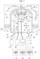
- the composition analysis device 10 includes a Raman scattered light acquisition device 11 which acquires Raman scattered light from a fluid G irradiated with laser light which is excitation light and an analyzing device 70 which analyzes a composition of the fluid G on the basis of the Raman scattered light acquired by the Raman scattered light acquisition device 11.
- the Raman scattered light may also be simply referred to as "scattered light" in some cases.
- the Raman scattered light acquisition device 11 includes a scattered light acquisition head 12, an analyzing laser oscillator (a light emission unit) 61, a heating laser oscillator 62, a control unit 81 which controls the laser oscillators 61 and 62, two determination units 65 and 66 which determine the intensity of laser light, and a determination unit 82 which determines a state of the scattered light acquisition head 12 in accordance with outputs from the two determination units 65 and 66.
- a scattered light acquisition head 12 an analyzing laser oscillator (a light emission unit) 61, a heating laser oscillator 62, a control unit 81 which controls the laser oscillators 61 and 62, two determination units 65 and 66 which determine the intensity of laser light, and a determination unit 82 which determines a state of the scattered light acquisition head 12 in accordance with outputs from the two determination units 65 and 66.
- the analyzing laser oscillator 61 oscillates laser light with which the fluid G is irradiated.
- the heating laser oscillator 62 oscillates laser light which heats a part of the scattered light acquisition head 12.
- the scattered light acquisition head 12 includes a head casing 13, an emission optical system 21 which guides laser light from the analyzing laser oscillator 61 which is a light emission unit into the fluid G, a laser light receiving optical system (an excitation light receiving optical system) 31 which receive laser light which has passed through the fluid G, a scattered light window 42 which defines a part of a flow path of the fluid G and through which Raman scattered light from the fluid G passes, a scattered light receiving device 44 which receives the Raman scattered light which has passed through the scattered light window 42, a light shielding member 50 in contact with the scattered light window 42, and a heating optical fiber cable 55 which guides heating laser light to the light shielding member 50.
- an emission optical system 21 which guides laser light from the analyzing laser oscillator 61 which is a light emission unit into the fluid G
- a laser light receiving optical system (an excitation light receiving optical system) 31 which receive laser light which has passed through the fluid G
- a scattered light window 42 which defines a part of a flow path of the fluid G and through
- the emission optical system 21 includes an emission optical fiber cable 25 through which laser light from the analyzing laser oscillator 61 passes, an emission prism (a changer) 23 which changes a direction of laser light emitted from the emission optical fiber cable 25, and a laser emission window 22 which defines a part of the flow path of the fluid G and through which laser light passes.
- the emission optical fiber cable 25 has an optical fiber (not shown), a covering member (not shown) which covers the outer circumference of the optical fiber, and a sleeve 27 which covers an outer circumference of an end of the optical fiber.
- the sleeve 27 of the emission optical fiber cable 25 on an emission side thereof is attached to the head casing 13.
- the emission prism 23 perpendicularly bends an optical axis of laser light emitted from the emission optical fiber cable 25.
- the emission prism 23 makes an optical axis of laser light which has passed through the emission prism 23 perpendicular to an optical axis Ao of an emission surface of the emission optical fiber cable 25.
- the optical axis Ao of the emission surface is an optical axis of an emission surface 26 from which laser light is emitted through the emission optical fiber cable 25.
- the emission prism 23 is arranged in the head casing 13 and is fixed to the head casing 13.
- Laser light whose direction is changed through the emission prism 23 passes through the laser emission window 22.
- An inner surface 22i in the laser emission window 22 which defines the flow path of the fluid G and an outer surface 22o in the laser emission window 22 on the emission prism 23 side are both perpendicular to an optical axis of laser light which has passed through the emission prism 23. For this reason, an optical axis of laser light which has passed through the emission prism 23 and which does not reach the laser emission window 22 coincides with an optical axis Aw in a fluid which is an optical axis of laser light which has passed through the laser emission window 22 and has reached the fluid G.
- the laser emission window 22 is fixed to the head casing 13.
- the emission optical system 21 described above does not have a condensing optical system. However, a condensing optical system which condenses laser light emitted from the emission optical fiber cable 25 into the fluid G may be provided.
- the laser light receiving optical system (the excitation light receiving optical system) 31 includes a laser receiving window 32 which defines a part of the flow path of the fluid G and through which laser light passes, a light receiving prism 33 which changes a direction of laser light which has passed through the laser receiving window 32, a laser receiving optical fiber cable 35 on which laser light which has passed through the light receiving prism 33 is incident, and a condensing optical system 34 which condenses laser light which has passed through the light receiving prism 33 on a light receiving surface 36 of the laser receiving optical fiber cable 35.
- the laser receiving window 32 is arranged above the optical axis Aw in the fluid.
- the inner surface 32i in the laser receiving window 32 which defines the flow path of the fluid G and the outer surface 32o in the laser receiving window 32 on the light receiving prism 33 side are both perpendicular to the optical axis Aw in the fluid. For this reason, an optical axis of laser light which has passed through the laser receiving window 32 coincides with the optical axis Aw in the fluid.
- the laser receiving window 32 is fixed to the head casing 13.
- the light receiving prism 33 perpendicularly bends an optical axis of laser light which has passed through the laser receiving window 32. In other words, the light receiving prism 33 makes the optical axis of the laser light which has passed through the light receiving prism 33 perpendicular to the optical axis Aw in the fluid.
- the light receiving prism 33 is arranged in the head casing 13 and is fixed to the head casing 13.
- the laser receiving optical fiber cable 35 has an optical fiber (not shown), a covering member (not shown) which covers an outer circumference of the optical fiber, and a sleeve 37 which covers an outer circumference of an end of the optical fiber.
- the sleeve 37 of the laser receiving optical fiber cable 35 on a light receiving side thereof is attached to the head casing 13.
- a light receiving surface optical axis Ai of the laser receiving optical fiber cable 35 coincides with the optical axis of the laser light which has passed through the light receiving prism 33.
- the light receiving surface optical axis Ai is an optical axis of the light receiving surface 36 in the laser receiving optical fiber cable 35 which receives the laser light from the light receiving prism 33.
- a direction in which the optical axis Aw in the fluid extends is assumed to be an "optical axis direction Da.”
- a direction in which the light receiving surface 36 of the laser receiving optical fiber cable 35 is present with respect to the optical axis Aw in the fluid among directions perpendicular to the optical axis Aw in the fluid is assumed to be a "radial direction Dr.”
- a side closer to the optical axis Aw in the fluid is assumed to be a radially inward side Dri and an opposite side is assumed to be a radially outward side Dro.
- the scattered light window 42 is arranged at a position in which the scattered light window 42 is separated from the optical axis Aw in the fluid in the radial direction Dr within the range Rw in which the optical path of the laser light in the fluid G is present in the optical axis direction Da.
- the inner surface 42i in the scattered light window 42 which defines the flow path of the fluid G and the outer surface 42o which is a surface in the scattered light window 42 opposite to the inner surface 42i are both parallel to the optical axis Aw in the fluid.
- the inner surface 42i of the scattered light window 42 faces the radially inward side Dri and the outer surface 42o of the scattered light window 42 faces the radially outward side Dro.
- the scattered light receiving device 44 has a scattered light optical fiber cable 45 configured to receive scattered light which has passed through the scattered light window 42.
- a light receiving surface 46 of the scattered light optical fiber cable 45 is arranged at a position in which the light receiving surface 46 is separated from the optical axis Aw in the fluid in the radial direction Dr within the range Rw in which the optical path of the laser light in the fluid G is present in the optical axis direction Da, as in the scattered light window 42.
- the light receiving surface 46 is located on the radially outward side Dro with respect to the scattered light window 42 and faces the radially inward side Dri.
- the scattered light optical fiber cable 45 has an optical fiber (not shown), a covering member (not shown) which covers an outer circumference of the optical fiber, and a sleeve 47 which covers an outer circumference of an end of the optical fiber.
- the sleeve 47 of the scattered light optical fiber cable 45 on a light receiving side thereof is attached to the head casing 13.
- the emission surface 26 of the emission optical fiber cable 25, the light receiving surface 36 of the laser receiving optical fiber cable 35, and the light receiving surface 46 of the scattered light optical fiber cable 45 are all arranged at positions in which they are separated from the optical axis Aw in the fluid in the radial direction Dr. Furthermore, the emission surface 26 of the emission optical fiber cable 25, the light receiving surface 36 of the laser receiving optical fiber cable 35, and the light receiving surface 46 of the scattered light optical fiber cable 45 are all surfaces parallel to the optical axis Aw in the fluid.
- the emission surface optical axis Ao of the emission optical fiber cable 25 the light receiving surface optical axis Ai of the laser receiving optical fiber cable 35, and a light receiving surface optical axis Ars of the scattered light optical fiber cable 45 are all parallel to each other and are perpendicular to the optical axis Aw in the fluid.
- the light shielding member 50 is adhered to the outer surface 42o of the scattered light window 42 with an adhesive or the like.
- the light shielding member 50 is formed of a member through which laser light or Raman scattered light does not pass, which easily absorbs the energy of the laser light or the Raman scattered light, and which has good thermal conductivity.
- the light shielding member 50 is formed of copper, brass, or an alloy containing these.
- an outer shape of the light shielding member 50 is annular. An inside of this annular shape forms an optical path through which scattered light passes.
- An annular cavity 51 which extends along the outer surface 42o of the scattered light window 42 and matches the outer shape of the light shielding member 50 is formed inside the light shielding member 50.
- the heating optical fiber cable 55 has an optical fiber (not shown), a covering member (not shown) which covers an outer circumference of the optical fiber, and a sleeve 57 which covers an outer circumference of an end of the optical fiber.
- the sleeve 57 of the heating optical fiber cable 55 on an emission side thereof is attached to the light shielding member 50.
- the sleeve 57 of the heating optical fiber cable 55 is attached to the light shielding member 50 from a direction inclined with respect to an inner surface of the cavity of the light shielding member 50 and the outer surface 42o of the scattered light window 42 so that laser light from the heating optical fiber cable 55 is emitted into the cavity 51 of the light shielding member 50.
- the head casing 13 has a main body section 14 and two protrusion sections 15 and 16.
- a part of the sleeve 27 of the emission optical fiber cable 25, a part of the sleeve 37 of the laser receiving optical fiber cable 35, the condensing optical system 34, the sleeve 47 of the scattered light optical fiber cable 45, the light shielding member 50, and the sleeve 57 of the heating optical fiber cable 55 are accommodated in the main body section 14 and they are attached to the main body section 14.
- An attachment flange 17 configured to attach the head casing 13 to a pipe 131p through which a fluid G flows is provided in the main body section 14.
- the pipe 131p is a pipe which constitutes the BFG line 131 through which a BFG flows.
- the two protrusion sections 15 and 16 protrude from the main body section 14 in a direction in which the two protrusion sections 15 and 16 become further away from the attachment flange 17.
- the two protrusion sections 15 and 16 are separated from each other in a direction perpendicular to a direction in which the protrusion sections 15 and 16 protrude from the main body section 14.
- the emission prism 23 is accommodated in a first protrusion section 15 of the two protrusion sections 15 and 16 and the emission prism 23 is attached to the first protrusion section 15.
- the light receiving prism 33 is accommodated in a second protrusion section 16 which is the other protrusion section of the two protrusion sections 15 and 16 and the light receiving prism 33 is attached to the second protrusion section 16.
- the laser emission window 22 is attached to a surface in the first protrusion section 15 facing the second protrusion section 16. Furthermore, the laser receiving window 32 is attached to a surface in the second protrusion section 16 facing the first protrusion section 15.
- the direction in which the two protrusion sections 15 and 16 are separated is the optical axis direction Da.
- a direction in which the two protrusion sections 15 and 16 protrude from the main body section 14 is the radial direction Dr.
- the scattered light window 42 is attached to a surface of the main body section 14 on the radially inward side Dri thereof between the two protrusion sections 15 and 16 in the optical axis direction Da.
- An emitted light determination unit 65 which is one determination unit of the two determination units 65 and 66 determines the intensity of laser light oscillated from the analyzing laser oscillator 61 or laser light passing through the emission optical fiber cable 25.
- a light receiving determination unit 66 which is the other determination unit of the two determination units 65 and 66 determines the intensity of laser light which has passed through the laser receiving optical fiber cable 35.
- the determination unit 82 determines a state of the scattered light acquisition head 12 in accordance with outputs from the two determination units 65 and 66. To be specific, for example, when a difference between the light intensity determined by the emitted light determination unit 65 and the light intensity determined by the light receiving determination unit 66 is a predetermined value or more, it is determined that the scattered light acquisition head 12 is abnormal. Examples of a form of an abnormality determined by the determination unit 82 include the following forms. There is an abnormal form of a direction of the optical axis Ao of the emission surface of an emitted light optical fiber cable and a direction of the light receiving surface optical axis Ai of the laser receiving optical fiber cable 35.
- the analyzing device 70 includes a spectroscope 71 which disperses scattered light received by the scattered light optical fiber cable 45 into light for each of a plurality of wavelength bands, a camera 72 which outputs light for each of the plurality of wavelength bands dispersed using the spectroscope 71 as a digital signal, and an analyzing unit 83 which analyzes a composition in the fluid G on the basis of the digital signal associated with the light for each of the plurality of wavelength bands.
- a computer 80 has, as functional constitutions, the control unit 81, the determination unit 82 and the analyzing unit 83 described above. All of the control unit 81, the determination unit 82, and the analyzing unit 83 are constituted to have a program stored in a memory or the like of the computer 80 and a central processing unit (CPU) which executes this program.
- CPU central processing unit
- the control device 140 can communicate with the computer 80. For example, the control device 140 outputs (displays) the determination result using the determination unit 82. Furthermore, the control device 140 controls a degree of opening of the circulation amount adjustment valve 137, a degree of opening of the inlet guide vane 113, and in some cases, a degree of opening of the COG adjustment valve 136 and the like in accordance with the analysis result using the analyzing unit 83.
- composition analysis device 10 An operation of the composition analysis device 10 described above will be described below.
- the laser light oscillated from the analyzing laser oscillator 61 is incident on the emission optical fiber cable 25 and passes through the emission optical fiber cable 25.
- the optical axis of the laser light emitted from the emission optical fiber cable 25 is bent perpendicularly through the emission prism 23.
- the fluid G in the pipe 131p is irradiated with the laser light whose optical axis is bent through the laser emission window 22.
- Raman scattered light with a specific wavelength is generated for each component in the fluid G.
- Raman scattered light whose wavelength is shifted from a wavelength of laser light by a specific amount of shift is generated for each component in the fluid G.
- Scattered light is received by the scattered light optical fiber cable 45 through the scattered light window 42.
- the scattered light is guided to the spectroscope 71 of the analyzing device 70 through the scattered light optical fiber cable 45.
- the spectroscope 71 disperses incident scattered light for each of the plurality of wavelength bands.
- the camera 72 converts a light intensity for each of the plurality of wavelength bands dispersed using the spectroscope 71 into a digital signal and outputs the converted digital signal to the analyzing unit 83 of the computer 80.
- the analyzing unit 83 analyzes a composition in the fluid G on the basis of a digital signal associated with light for each of the plurality of wavelength bands.
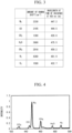
- the analyzing unit 83 pre-stores a relationship between a wavelength of laser light with which the fluid G is irradiated and an amount of shift of a wavelength of scattered light emitted from each component when the laser light is radiated.
- the analyzing unit 83 analyzes the component in the fluid G using this relationship. Furthermore, the analyzing unit 83 obtains a concentration of the component in the fluid G on the basis of an intensity of scattered light for each component.
- the fluid G is a BFG which is a gas
- the analyzing unit 83 obtains a high heating value (HHV) or a low heating value (LHV) of the BFG if necessary.
- the following Expression (1) is an expression for obtaining a high heating value (HHV) per unit volume of the BFG when the BFG includes carbon dioxide (CO 2 ), carbon monoxide (CO), nitrogen (N 2 ), methane (CH 4 ), water vapor (H 2 O), or hydrogen (H 2 ) as illustrated in Fig. 4 .
- the following Expression (2) is an expression for obtaining a low heating value (LHV) per unit volume of the BFG in the same case.
- HHV 3020 ⁇ CCO + 3050 ⁇ CH 2 + 9520 ⁇ CCH 4
- LHV 3020 ⁇ CCO + 2570 ⁇ CH 2 + 8550 ⁇ CCH 4
- the HHV is a calorific value (kcal/m 3 N) in which the heat of condensation of water generated through combustion of the BFG is included as a calorific value.
- the LHV is a calorific value (kcal/m 3 N) in which the heat of condensation of water generated through combustion of the BFG is not included as a calorific value.
- CN 2 is a mole fraction of N 2
- CCO is a mole fraction of CO
- CCO 2 is a mole fraction of CO 2
- CH 2 O is a mole fraction of H 2 O
- CH 2 is a mole fraction of H 2
- CCH 4 is a mole fraction of CH 4 .
- CCO 2 ⁇ CO 2 ⁇ ICO 2 IN 2 1 + ⁇ CO ⁇ ICO IN 2 + ⁇ CO 2 ⁇ ICO 2 IN 2 + ⁇ H 2 O ⁇ IH 2 O IN 2 + ⁇ H 2 ⁇ IH 2 IN 2 + ⁇ CH 4 ⁇ ICH 4 IN 2 [Math. 6]
- CH 2 O ⁇ H 2 O ⁇ IH 2 O IN 2 1 + ⁇ CO ⁇ ICO IN 2 + ⁇ CO 2 ⁇ ICO 2 IN 2 + ⁇ H 2 O ⁇ IH 2 O IN 2 + ⁇ H 2 ⁇ IH 2 IN 2 + ⁇ CH 4 ⁇ ICH 4 IN 2 [Math.
- CH 2 ⁇ H 2 ⁇ IH 2 IN 2 1 + ⁇ CO ⁇ ICO IN 2 + ⁇ CO 2 ⁇ ICO 2 IN 2 + ⁇ H 2 O ⁇ IH 2 O IN 2 + ⁇ H 2 ⁇ IH 2 IN 2 + ⁇ CH 4 ⁇ ICH 4 IN 2
- CCH 4 ⁇ CH 4 ⁇ ICH 4 IN 2 1 + ⁇ CO ⁇ ICO IN 2 + ⁇ CO 2 ⁇ ICO 2 IN 2 + ⁇ CO 2 ⁇ IH 2 O IN 2 + ⁇ H 2 ⁇ IH 2 IN 2 + ⁇ CH 4 ⁇ ICH 4 IN 2
- the analyzing unit 83 obtains a relative intensity ICO/IN 2 of a carbon monoxide component with respect to a light intensity IN 2 of a nitrogen component, a relative intensity ICO 2 /IN 2 of a carbon dioxide component to the light intensity IN 2 of the nitrogen component, a relative intensity IH 2 O/IN 2 of a water vapor component to the light intensity IN 2 of the nitrogen component, a relative intensity IH 2 /IN 2 of a hydrogen component to the light intensity IN 2 of the nitrogen component, and a relative intensity ICH 4 /IN 2 of a methane component to the light intensity IN 2 of the nitrogen component from the intensity of the scattered light for each component in the BFG.
- the analyzing unit 83 obtains the high heating value (HHV) or the low heating value (LHV) of the BFG using the relative intensity of each of the components, Expression (1) or (2) and Expressions (3) to (8).
- Expressions (1) to (8) are the expressions associated with a volume ratio in which H 2 O is taken into consideration, a calorific value may be obtained using an expression associated with a volume ratio of the gas in which H 2 O is excluded.
- the concentration of the component in the fluid G, the low heating value (LHV), or the like obtained using the analyzing unit 83 is transmitted to the control device 140 of the gas turbine plant.
- the control device 140 controls the degree of opening of the circulation amount adjustment valve 137, the degree of opening of the inlet guide vane 113, and the like on the basis of data transmitted from the analyzing unit 83, that is, the analysis result.
- the laser light which has passed through the fluid G is incident on the light receiving prism 33 through the laser receiving window 32.
- An optical axis of the laser light is perpendicularly bent through the light receiving prism 33.
- the laser light whose optical axis is bent is condensed through the light receiving surface 36 of the laser receiving optical fiber cable 35 using the condensing optical system 34.
- the light receiving determination unit 66 determines the intensity of the laser light incident on the laser receiving optical fiber cable 35.
- the intensity of laser light determined by the emitted light determination unit 65 and the intensity of laser light determined by the light receiving determination unit 66 are transmitted to the determination unit 82 of the computer 80.
- the determination unit 82 determines a state of the scattered light acquisition head 12 in accordance with the intensity of the laser light determined by each of the determination units 65 and 66.
- the determination result of the determination unit 82 is transmitted to the control device 140 of the gas turbine plant.
- the control device 140 causes the determination result of the determination unit 82 to be displayed if necessary.
- the laser light oscillated from the heating laser oscillator 62 is guided into the cavity 51 of the light shielding member 50 through the heating optical fiber cable 55.
- the laser light is repeatedly irregularly reflected by the inner surface of the cavity in the cavity 51 of the light shielding member 50.
- light energy of the laser light is converted into heat energy using which the light shielding member 50 and the scattered light window 42 in contact with the light shielding member 50 are heated. That is to say, in this embodiment, the scattered light window 42 is heated using the energy of the laser light.
- the laser light from the heating optical fiber cable 55 is guided into the cavity 51 of the light shielding member 50 in this embodiment, it is possible to irradiate the light shielding member 50 with all of the laser light and it is possible to increase the efficiency of converting the light energy of the laser light into heat energy.
- the inner surface 22i of the laser emission window 22 which partitions the inside of the head casing 13 and the flow path of the fluid G, the inner surface 32i of the laser receiving window 32, and the inner surface 42i of the scattered light window 42 become contaminated by the foreign matter.
- the fluid G is one of a blast furnace gas (BFG) and a coke oven gas (COG) or a mixed gas of BFG and COG, foreign matter such as ash becomes present in the fluid G.
- An intensity of the Raman scattered light is much smaller than an intensity of the laser light with which the fluid G is irradiated. For this reason, if the inner surface 42i of the scattered light window 42 is dirty, the foreign matter hinders the composition analysis of the fluid G based on the scattered light. Thus, in this embodiment, as described above, foreign matter adhered to the inner surface 42i of the scattered light window 42 is removed and adhering of foreign matter to the inner surface 42i of the scattered light window 42 is prevented by heating the scattered light window 42.
- a method of heating the scattered light window 42 there is a method of heating the scattered light window 42 wire by bringing the heating wire into contact with or into proximity to the scattered light window 42 and causing a current to pass through the heating wire.
- the heating wire is brought into contact with or into proximity to the scattered light window 42 if the fluid G is a combustible gas such as a BFG or a COG
- explosion-proof treatment needs to be applied to a heating wire or an electric cable through which a current is supplied to the heating wire.
- electricity is not used to heat the scattered light window 42 in this embodiment, it is not necessary to apply explosion-proof treatment to a component necessary for heating the scattered light window 42, specifically, the heating optical fiber cable 55 and the light heat shield member.
- it is possible to save the cost of the explosion-proof treatment for the component necessary for heating the scattered light window 42.
- the light receiving surface 46 of the scattered light receiving device 44 is arranged at a position in which the light receiving surface 46 is separated from the optical axis Aw in the fluid in the radial direction Dr within the range Rw in which the optical path of the laser light in the fluid G is present in the optical axis direction Da.
- the light receiving surface 46 of the scattered light receiving device 44 is arranged at a position in which the light receiving surface 46 is separated from a scattered light generation region Rrs in the fluid G in a direction in which the light receiving surface 46 is perpendicular to the optical axis Aw in the fluid.
- the light receiving surface 46 of the scattered light receiving device 44 can be brought into proximity to the scattered light generation region Rrs in the fluid G.
- the inner surface 42i and the outer surface 42o of the scattered light window 42 and the light receiving surface 46 of the scattered light receiving device 44 are parallel to the optical axis Aw in the fluid.
- the light receiving surface 46 of the scattered light receiving device 44 can be brought into proximity to the scattered light generation region Rrs in the fluid G.
- the light receiving surface 46 of the scattered light receiving device 44 can receive Raman scattered light with little attenuation.
- the condensing optical system configured to condense the scattered light which has passed through the scattered light window 42 can be omitted.
- the condensing optical system can be omitted by setting a distance from the optical axis Aw in the fluid to the light receiving surface 46 of the scattered light receiving device 44 in a radial direction (a direction perpendicular to the optical axis in the fluid) to be equal to or less than a distance in which an amount of Raman scattered light to be received by the scattered light receiving device 44 is a minimum amount of light in which the composition of the fluid G can be analyzed using the analyzing device 70.
- a distance from the optical axis Aw in the fluid to the light receiving surface 46 of the scattered light receiving device 44 in a radial direction (a direction perpendicular to the optical axis in the fluid) to be equal to or less than a distance in which an amount of Raman scattered light to be received by the scattered light receiving device 44 is a minimum amount of light in which the composition of the fluid G can be analyzed using the analyzing device 70.
- all of the emission surface optical axis Ao of the emission optical fiber cable 25, the light receiving surface optical axis Ai of the laser receiving optical fiber cable 35, and the light receiving surface optical axis Ars of the scattered light optical fiber cable 45 are parallel to each other and are perpendicular to the optical axis Aw in the fluid.
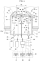
- composition analysis device in this embodiment is different from the composition analysis device in the first embodiment in that the emission prism 23 and the light receiving prism 33 are in contact with the fluid G and a plurality of light shielding members 50a are provided but the other points are basically the same as those of the composition analysis device in the first embodiment.
- the scattered light window 42a in this embodiment is arranged at a position in which the scattered light window 42a is separated from the optical axis Aw in the fluid in the radial direction Dr, as in the scattered light window 42a in the first embodiment. Also in the scattered light window 42a in this embodiment, both of the inner surface 42i which defines the flow path of the fluid G and the outer surface 42o which is a surface in the scattered light window 42 opposite to the inner surface 42i are parallel to the optical axis Aw in the fluid.
- the length of the scattered light window 42a in this embodiment in the optical axis direction Da is longer than that of the scattered light window 42 in the first embodiment.
- the scattered light window 42a in this embodiment extends in the optical axis direction Da to a position farther than a position of the emission surface optical axis Ao of the emission optical fiber cable 25 with reference to the light receiving surface optical axis Ars of the scattered light optical fiber cable 45. Furthermore, the scattered light window 42a in this embodiment extends in the optical axis direction Da to a position farther than a position of the light receiving surface optical axis Ai of the laser receiving optical fiber cable 35 with reference to the light receiving surface optical axis Ars of the scattered light optical fiber cable 45.
- the scattered light window 42a in this embodiment is also present in the optical axis direction Da at a position of the emission surface optical axis Ao of the emission optical fiber cable 25 and a position of the light receiving surface optical axis Ai of the laser receiving optical fiber cable 35.
- the scattered light passes through the scattered light window 42a in this embodiment within the range Rw in which the optical path of the laser light in the fluid G is present in the optical axis direction Da and the scattered light window 42a is subjected to a process of reflecting the laser light.
- the scattered light window 42a is not subjected to a process of reflecting laser light and the laser light passes through the scattered light window 42a outside of the range Rw.
- the emission optical system 21a in this embodiment has the emission optical fiber cable 25 through which laser light from the analyzing laser oscillator 61 passes, a part of the scattered light window 42a, and the emission prism (the changer) 23 which changes a direction of laser light which is emitted from the emission optical fiber cable 25 and has passed through the scattered light window 42a.
- An incident surface 23i of the emission prism 23 is in contact with the outer surface 42o of the scattered light window 42a.
- an emission surface 23o of the emission prism 23 forms a surface which defines the flow path of the fluid G. For this reason, the emission optical system 21a in this embodiment does not have the laser emission window 22.
- the laser light receiving optical system (the excitation light receiving optical system) 31a includes the light receiving prism 33 which changes a direction of laser light, a part of the scattered light window 42a, the laser receiving optical fiber cable 35, and the condensing optical system 34 which condenses laser light which has passed through the light receiving prism 33 and the scattered light window 42a to the light receiving surface 36 of the laser receiving optical fiber cable 35.
- the incident surface 23i of the light receiving prism 33 forms a surface which defines the flow path of the fluid G. For this reason, the laser light receiving optical system 31a in this embodiment does not have the laser receiving window 32.
- the emission surface 33o of the light receiving prism 33 is in contact with the outer surface 42o of the scattered light window 42a.
- the laser emission window 22 and the laser receiving window 32 in the first embodiment are not provided in this embodiment, it is possible to simplify a device and to minimize the production costs thereof.
- one light shielding member 50 is provided and an outer shape thereof is annular.
- a plurality of light shielding members 50a are provided. All of the plurality of light shielding members 50a are adhered to the outer surface 42o of the scattered light window 42a with an adhesive or the like.
- the light shielding member 50 is formed of a member through which laser light or Raman scattered light is not transmitted, which easily absorbs the energy of the laser light or the Raman scattered light, and which has good thermal conductivity.
- the plurality of light shielding members 50a are separated from each other in a circumferential direction with respect to the light receiving surface optical axis Ars of the scattered light optical fiber cable 45.
- the sleeve 57 of the heating optical fiber cable 55 is attached to each of the plurality of light shielding members 50a, as in the first embodiment.
- the heating laser oscillator 62 is connected to each heating optical fiber cable 55.
- one light shielding member may be provided or a plurality of light shielding members may be provided.
- the laser emission window 22 and the laser receiving window 32 are in contact with the scattered light window 42a.
- the scattered light window 42a is heated using the energy of the laser light oscillated from the heating laser oscillator 62, the emission prism 23 and the light receiving prism 33 are also heated. For this reason, it is possible to remove foreign matter in the fluid G adhered to the emission surface 23o of the emission prism 23 and the incident surface 33i of the light receiving prism 33 and to prevent adhering of foreign matter to the emission surface 23o of the emission prism 23 and the incident surface 33i of the light receiving prism 33.
- the fact that B is perpendicular to A means not only that an angle of B with respect to A is 90° but also that the angle of B with respect to A is about 88° to 92° and B is substantially perpendicular to A.
- the fact that A and B are parallel to each other means not only that an angle of B with respect to A is 0° but also that the angle of B with respect to A is about -2° to +2° and B is substantially parallel to A.
- the laser light receiving optical system (the excitation light receiving optical system) 31 or 31a has the condensing optical system 34.
- the condensing optical system 34 may be omitted.
- the laser light receiving optical system (the excitation light receiving optical system) 31 or 31a in the above embodiment is an optical system provided for determining an abnormality of the scattered light acquisition head 12. Thus, when it is not necessary to determine an abnormality of the scattered light acquisition head 12, the laser light receiving optical system (the excitation light receiving optical system) 31 or 31a may be omitted.
- the changer in the above embodiment is the emission prism 23 or the light receiving prism 33.
- the changer may be a mirror.
- the scattered light receiving device 44 in the above embodiment does not have a condensing optical system.
- the scattered light receiving device 44 may have a condensing optical system.
- the fluid G to be analyzed in the above embodiment is a gas G which is unmixed BFG.
- the fluid G to be analyzed may be unmixed COG, a mixture of a BFG and a COG, or a mixture of a BFG, a COG, and a LDG.
- the fluid G to be analyzed may be another fuel gas, for example, natural gas, biogas, or the like.
- the fluid G to be analyzed may not be a fuel gas.
Landscapes
- Physics & Mathematics (AREA)
- Chemical & Material Sciences (AREA)
- Health & Medical Sciences (AREA)
- Engineering & Computer Science (AREA)
- General Physics & Mathematics (AREA)
- Life Sciences & Earth Sciences (AREA)
- Spectroscopy & Molecular Physics (AREA)
- Analytical Chemistry (AREA)
- Immunology (AREA)
- Pathology (AREA)
- General Health & Medical Sciences (AREA)
- Biochemistry (AREA)
- Nuclear Medicine, Radiotherapy & Molecular Imaging (AREA)
- Combustion & Propulsion (AREA)
- Oil, Petroleum & Natural Gas (AREA)
- General Chemical & Material Sciences (AREA)
- Medicinal Chemistry (AREA)
- Food Science & Technology (AREA)
- Chemical Kinetics & Catalysis (AREA)
- Fluid Mechanics (AREA)
- Mechanical Engineering (AREA)
- General Engineering & Computer Science (AREA)
- Investigating, Analyzing Materials By Fluorescence Or Luminescence (AREA)
Description
- The present invention relates to a Raman scattered light acquisition device which acquires Raman scattered light from a fluid, a composition analysis device including the same, and a gas turbine plant.
- As a method of analyzing a composition of a fluid, there are methods of analyzing Raman scattered light from a fluid irradiated with excitation light by irradiating the fluid with excitation light. Examples of devices which perform these methods include the composition analysis device described in
Patent Document 1 which will be described below. The composition analysis device includes a measurement cell having a fluid flowing therein, a laser oscillator which oscillates laser light which is excitation light, an emission optical system which irradiates the fluid in the measurement cell with laser light from the laser oscillator, a light receiving optical system which receives Raman scattered light from the fluid irradiated with laser light, an optical fiber which receives the Raman scattered light condensed using the light receiving optical system, and an analyzing device which is configured to analyze light received using the optical fiber. - An optical axis of the emission optical system extends in a flow perpendicular direction perpendicular to a main flow direction of the fluid flowing in the measurement cell. The emission optical system is provided on one side in the flow perpendicular direction with reference to the measurement cell. An optical axis of the light receiving optical system coincides with the optical axis of the emission optical system. Thus, the optical axis of the light receiving optical system also extends in the flow perpendicular direction. The light receiving optical system is provided on the other side in the flow perpendicular direction with reference to the measurement cell.
-
- [Patent Document 1]
Japanese Unexamined Patent Application, First Publication No. 2015-072179 - [Patent Document 2]
WO 2014/082957 A1 - [Patent Document 3]
JP H06 277173 A - [Patent Document 2] discloses an optical measurement probe device for carrying out spectrometric and/or photometric measurements in a fluid, including a body, at least a first and a second arm extending to the end of said body and aligned with same, and defining a measurement cavity, a plurality of optical fibers inserted in said body, and optical coupling means capable of transmitting light between at least one portion of said optical fibers and the measurement cavity.
- [Patent Document 3] discloses that four heat receiving fins projecting outward in the radial direction are arranged on a lens cylinder of an incident hole lens set on an observation window of an insertion part so as to shift the phase thereof each other by 90° and an illuminating light projected from a light guide is used as a heat source and this heat is transmitted to the incident hole lens through the lens cylinder from the heat receiving fins to heat them incident hole lens. This heat receiving fins are inserted in recessed parts formed on the projecting end face of the light guide and are brought into contact with this projecting end face.
- In the composition analysis industry, it is desired to reduce the size of a composition analysis device.
- Therefore, an object of the present invention is to provide a technique capable of reducing a size of a device.
- According to the present invention, there is provided a Raman scattered light acquisition device as set out in
independent claim 1. Advantageous developments are defined in the dependent claims. - A Raman scattered light acquisition device as an aspect associated with the invention (which is defined with claim 1) for achieving the above object includes: an emission optical system which is configured to guide excitation light from a light emission unit into a fluid; a scattered light window which is configured to define a part of a flow path of the fluid and through which Raman scattered light from the fluid irradiated with the excitation light passes; and a scattered light receiving device which has a light receiving surface receiving the Raman scattered light which has passed through the scattered light window, wherein the scattered light window and the light receiving surface of the scattered light receiving device are disposed at positions in which the scattered light window and the light receiving surface are separated from an optical axis in the fluid in a radial direction which is a direction perpendicular to the optical axis in the fluid within a range in which an optical path of the excitation light in the fluid is present in an optical axis direction in which the optical axis in the fluid which is an optical axis of the excitation light in the fluid extends, and the light receiving surface faces a radially inward side which is a side in proximity to the optical axis in the fluid in the radial direction.
- In this aspect, the light receiving surface of the scattered light receiving device is arranged at a position in which the light receiving surface is separated from a scattered light generation region in the fluid in the direction perpendicular to the optical axis in the fluid. For this reason, in this aspect, the light receiving surface of the scattered light receiving device can be brought into proximity to the scattered light generation region in the fluid. Thus, in this aspect, it is possible to reduce a size of the Raman scattered light acquisition device.
- Also, in this aspect, the light receiving surface of the scattered light receiving device can be brought into proximity to the scattered light generation region in the fluid. Thus, the light receiving surface of the scattered light receiving device can receive Raman scattered light with little attenuation. For this reason, in this aspect, the condensing optical system configured to condense scattered light which has passed through the scattered light window can be omitted. Thus, in this aspect, also from this viewpoint, it is possible to reduce the size of the Raman scattered light acquisition device.
- Here, in the Raman scattered light acquisition device, a light receiving surface optical axis which is the optical axis in the light receiving surface of the scattered light receiving device may be perpendicular to the optical axis in the fluid.
- In this aspect, it is possible to efficiently receive Raman scattered light which travels in the direction perpendicular to the optical axis in the fluid with a short optical path length.
- Also, in any of the above Raman scattered light acquisition devices, the inner surface in the scattered light window which is configured to define the flow path of the fluid and the outer surface opposite to the inner surface may be both parallel to the optical axis in the fluid.
- In this aspect, the Raman scattered light emitted in the direction perpendicular to the optical axis in the fluid in the Raman scattered light emitted from the fluid can be made to travel in a straight line. For this reason, it is possible to shorten an optical path length of scattered light from the optical axis in the fluid to the light receiving surface of the scattered light receiving device.
- In any of the above Raman scattered light acquisition devices, the emission optical system may include an emission optical fiber cable through which the excitation light from the light emission unit passes and a changer which is configured to change a direction of the excitation light emitted from the emission optical fiber cable. In this case, an emission surface optical axis which is an optical axis in an emission surface of the emission optical fiber cable which emits the excitation light may extend in a direction intersecting the optical axis in the fluid. The emission surface of the emission optical fiber cable and the changer may be arranged on one side in the optical axis direction with reference to the light receiving surface of the scattered light receiving device and the changer may cause the optical axis of the excitation light emitted from the emission optical fiber cable to coincide with the optical axis in the fluid.
- In this aspect, a width of the Raman scattered light acquisition device in the optical axis direction can be reduced.
- Also, in the Raman scattered light acquisition device having the emission optical fiber cable, the emission surface optical axis may be perpendicular to the optical axis in the fluid.
- In this aspect, the width of the Raman scattered light acquisition device in the optical axis direction can be made smaller.
- Any of the above Raman scattered light acquisition devices may include: a light shielding member through which the excitation light and the Raman scattered light do not pass; and a heating optical fiber cable using which the light shielding member is irradiated with excitation light. The light shielding member is in contact with an outer surface of the scattered light window on the light receiving surface side.
- In this aspect, it is possible to heat the scattered light window using energy of the excitation light. For this reason, in this aspect, it is possible to remove foreign matter adhered to the inner surface of the scattered light window and to prevent adhering of foreign matter to the scattered light window.
- Also, since electricity is not used to heat the scattered light window in this aspect, an explosion-proofing treatment necessary for components for heating the scattered light window, that is, for the heating optical fiber cable and the heating light shielding member can be omitted.
- In the Raman scattered light acquisition device including the light shielding member, a cavity which extends along the outer surface of the scattered light window is formed inside the light shielding member and the heating optical fiber cable is configured to emit into the cavity of the light shielding member.
- Since the light shielding member can be irradiated with all of the excitation light in this aspect, it is possible to increase the efficiency of converting light energy of the excitation light into heat energy.
- The Raman scattered light acquisition device includes an excitation light receiving optical system which is configured to receive the excitation light from the emission optical system; and a determination unit which is configured to determine an abnormality of an excitation light optical system constituted of a plurality of members through which the excitation light passes in accordance with a difference between the light intensity of the excitation light from the light emission unit and the light intensity of the excitation light received by the excitation light receiving optical system.
- In this aspect, it is possible to recognize an abnormality in the excitation light optical system constituted of the plurality of members through which the excitation light passes.
- In the Raman scattered light acquisition device including the excitation light receiving optical system, the excitation light receiving optical system may be arranged on a side opposite to the emission optical system in the optical axis direction with reference to the light receiving surface of the scattered light receiving device.
- Any of the above Raman scattered light acquisition devices may include the light emission unit.
- A composition analysis device as an aspect associated with the invention for achieving the above object includes: any of the above Raman scattered light acquisition devices; and an analyzing device which is configured to analyze a composition of the fluid on the basis of an output from the scattered light receiving device.
- In this aspect, it is possible to analyze the composition of the fluid.
- Here, in the composition analysis device, a distance in the radial direction from the optical axis in the fluid to the light receiving surface of the scattered light receiving device may be equal to or less than a distance in which an amount of the Raman scattered light received by the scattered light receiving device is a minimum amount of light in which the analyzing device is able to analyze the composition of the fluid.
- A gas turbine plant as an aspect associated with the invention for achieving the above object includes: any of the above composition analysis devices; a fuel gas line through which a fuel gas as the fluid flows; a fuel adjustment valve which is configured to adjust a flow rate of the fuel gas flowing through the fuel gas line; a gas turbine configured to be driven through combustion of the fuel gas from the fuel gas line; and a control device which is configured to instruct a degree of opening of the fuel adjustment valve. The Raman scattered light acquisition device is attached to the fuel gas line. The analyzing device is configured to analyze a composition of the fuel gas flowing in the fuel gas line. The control device is configured to determine the degree of opening of the fuel adjustment valve in accordance with the analysis results in the analyzing device and instruct the degree of opening to the fuel adjustment valve.
- According to the present invention, it is possible to reduce the size of a device.
-
-
Fig. 1 is a schematic diagram illustrating a constitution of a composition analysis device according to a first embodiment of the present invention. -
Fig. 2 is a perspective view of a light heat shield member and a heating optical fiber according to the first embodiment of the present invention. -
Fig. 3 is an explanatory diagram illustrating an amount of shift of a wavelength of Raman scattered light emitted from each component with respect to a wavelength of excitation light with which a fluid is irradiated and a wavelength of Raman scattered light emitted from each component when the excitation light has a predetermined wavelength. -
Fig. 4 is a graph showing a relationship between a wavelength of Raman scattered light emitted from each component when a fluid is irradiated with excitation light and an intensity of each wavelength. -
Fig. 5 is a system diagram of a gas turbine plant according to an embodiment of the present invention. -
Fig. 6 is a schematic diagram illustrating a constitution of a composition analysis device according to a second embodiment of the present invention. - An embodiment of a composition analysis device associated with the present invention and an embodiment of a gas turbine plant including the composition analysis device will be described below with reference to the drawings.
- A first embodiment of the composition analysis device associated with the present invention and the embodiment of the gas turbine plant including the composition analysis device will be described with reference to
Figs. 1 to 5 . - A fluid analyzed by the composition analysis device in this embodiment is, for example, a fuel gas flowing in a pipe. To be specific, as illustrated in
Fig. 5 , the fluid is a fuel gas for driving a gas turbine of the gas turbine plant. - The gas turbine plant includes a
gas turbine 110, anelectric generator 120 which generates electricity through driving of thegas turbine 110, agas compressor 121 which compresses a fuel gas through driving of thegas turbine 110, acomposition analysis device 10 which analyzes a composition of a gas to be supplied to thegas turbine 110, and acontrol device 140 which controls a state or the like of thegas turbine 110. - The
gas turbine 110 includes anair compressor 111 which compresses air A to generate compressed air, acombustor 115 which combusts a fuel gas in the compressed air to generate a high-temperature combustion gas, and aturbine 116 which is driven using the combustion gas. - The
air compressor 111 includes a compressor rotor, a compressor casing which rotatably covers the compressor rotor, and anintake amount adjuster 112 which adjusts an amount of intake of the air A. Theintake amount adjuster 112 includes aninlet guide vane 113 provided on a suction port side of the compressor casing and aguide vane driver 114 which changes a degree of opening of theinlet guide vane 113. - The
turbine 116 includes a turbine rotor which rotates using a combustion gas and a turbine casing which rotatably covers the turbine rotor. The compressor rotor and the turbine rotor are connected to each other and integrally formed to form agas turbine rotor 117. - The
electric generator 120 includes an electric generator rotor and an electric generator casing which rotatably covers the electric generator rotor. The electric generator rotor is connected to thegas turbine rotor 117. For this reason, if thegas turbine rotor 117 rotates, the electric generator rotor also rotates integrally. - The
gas compressor 121 includes a compressor rotor, a compressor casing which rotatably covers the compressor rotor and an intakegas amount adjuster 122 which adjusts an amount of intake of a fuel gas. The intakegas amount adjuster 122 includes aninlet guide vane 123 provided on a suction port side of the compressor casing and aguide vane driver 124 which changes a degree of opening of theinlet guide vane 123. The compressor rotor of thegas compressor 121 is mechanically connected to the electric generator rotor or thegas turbine rotor 117 via aspeed reducer 126. A discharge port of thegas compressor 121 is connected to thecombustor 115 through a high-pressurefuel gas line 134. - A fuel gas is supplied from a
steel mill 151 and acoke plant 152 to the gas turbine plant. Thesteel mill 151 generates a blast furnace gas (BFG) as a low-calorie fuel gas from a blast furnace in thesteel mill 151. ABFG line 131 through which a BFG flows is connected to the blast furnace. Thecoke plant 152 generates a coke oven gas (COG) as a high-calorie fuel gas from a coke oven in thecoke plant 152. ACOG line 132 through which a COG flows is connected to the coke oven. ACOG adjustment valve 136 which adjusts a flow rate of the COG is provided in theCOG line 132. TheBFG line 131 and theCOG line 132 are joined to form a low-pressurefuel gas line 133. Any of an independent BFG, an independent COG, and a mixture of a BFG and a COG flows through the low-pressurefuel gas line 133. The low-pressurefuel gas line 133 is connected to the suction port of thegas compressor 121. An electrostatic precipitator (EP) 127 which collects dust and the like in a gas passing through the low-pressurefuel gas line 133 is provided in the low-pressurefuel gas line 133. A gas such as a Linz-Donawitz converter gas (LDG) which is a gas generated in a converter in the middle of theBFG line 131 may be mixed in in theBFG line 131 in some cases. - The gas turbine plant includes the
BFG line 131, theCOG line 132, the low-pressurefuel gas line 133, theCOG adjustment valve 136, and theelectrostatic precipitator 127 which have been described above. The gas turbine plant further includes a fuel gas circulation line 135, a circulationamount adjustment valve 137, and agas cooler 138. A first end of the fuel gas circulation line 135 is connected to the high-pressurefuel gas line 134. Furthermore, a second end of the fuel gas circulation line 135 is connected to a position of the low-pressurefuel gas line 133 upstream of theelectrostatic precipitator 127. Thegas cooler 138 and the circulationamount adjustment valve 137 are provided in the fuel gas circulation line 135. - The
gas cooler 138 cools a gas flowing through the fuel gas circulation line 135. If a degree of opening of the circulationamount adjustment valve 137 is changed and a flow rate of the gas flowing through the fuel gas circulation line 135 is changed, a flow rate of a gas supplied to thecombustor 115 is also changed. For this reason, the circulationamount adjustment valve 137 functions as a fuel adjustment valve which adjusts a flow rate of a fuel gas to be supplied to thecombustor 115. Furthermore, the intakegas amount adjuster 122 of thegas compressor 121 described above also functions as a fuel adjustment valve. Thecomposition analysis device 10 is provided in theBFG line 131. Thecomposition analysis device 10 analyzes a composition of a BFG flowing through theBFG line 131. Here, although thecomposition analysis device 10 is provided in theBFG line 131, thecomposition analysis device 10 may be provided in the low-pressurefuel gas line 133 or theCOG line 132 in some cases. - The
control device 140 controls a degree of opening of the circulationamount adjustment valve 137, a degree of opening of theinlet guide vane 113, or the like in accordance with a load command from the outside, a composition of a BFG which is a gas analyzed by thecomposition analysis device 10, or the like. Furthermore, thecontrol device 140 also controls a degree of opening of theCOG adjustment valve 136 in accordance with a load command from the outside, a composition of a gas G (a BFG) analyzed by thecomposition analysis device 10, or the like in some cases. - As illustrated in
Fig. 1 , thecomposition analysis device 10 includes a Raman scatteredlight acquisition device 11 which acquires Raman scattered light from a fluid G irradiated with laser light which is excitation light and an analyzingdevice 70 which analyzes a composition of the fluid G on the basis of the Raman scattered light acquired by the Raman scatteredlight acquisition device 11. - Hereinafter, the Raman scattered light may also be simply referred to as "scattered light" in some cases.
- The Raman scattered
light acquisition device 11 includes a scatteredlight acquisition head 12, an analyzing laser oscillator (a light emission unit) 61, aheating laser oscillator 62, acontrol unit 81 which controls thelaser oscillators determination units determination unit 82 which determines a state of the scatteredlight acquisition head 12 in accordance with outputs from the twodetermination units - The analyzing
laser oscillator 61 oscillates laser light with which the fluid G is irradiated. Theheating laser oscillator 62 oscillates laser light which heats a part of the scatteredlight acquisition head 12. - The scattered
light acquisition head 12 includes ahead casing 13, an emissionoptical system 21 which guides laser light from the analyzinglaser oscillator 61 which is a light emission unit into the fluid G, a laser light receiving optical system (an excitation light receiving optical system) 31 which receive laser light which has passed through the fluid G, a scatteredlight window 42 which defines a part of a flow path of the fluid G and through which Raman scattered light from the fluid G passes, a scatteredlight receiving device 44 which receives the Raman scattered light which has passed through the scatteredlight window 42, alight shielding member 50 in contact with the scatteredlight window 42, and a heatingoptical fiber cable 55 which guides heating laser light to thelight shielding member 50. - The emission
optical system 21 includes an emissionoptical fiber cable 25 through which laser light from the analyzinglaser oscillator 61 passes, an emission prism (a changer) 23 which changes a direction of laser light emitted from the emissionoptical fiber cable 25, and alaser emission window 22 which defines a part of the flow path of the fluid G and through which laser light passes. - The emission
optical fiber cable 25 has an optical fiber (not shown), a covering member (not shown) which covers the outer circumference of the optical fiber, and asleeve 27 which covers an outer circumference of an end of the optical fiber. Thesleeve 27 of the emissionoptical fiber cable 25 on an emission side thereof is attached to thehead casing 13. - The
emission prism 23 perpendicularly bends an optical axis of laser light emitted from the emissionoptical fiber cable 25. In other words, theemission prism 23 makes an optical axis of laser light which has passed through theemission prism 23 perpendicular to an optical axis Ao of an emission surface of the emissionoptical fiber cable 25. The optical axis Ao of the emission surface is an optical axis of anemission surface 26 from which laser light is emitted through the emissionoptical fiber cable 25. Theemission prism 23 is arranged in thehead casing 13 and is fixed to thehead casing 13. - Laser light whose direction is changed through the
emission prism 23 passes through thelaser emission window 22. An inner surface 22i in thelaser emission window 22 which defines the flow path of the fluid G and an outer surface 22o in thelaser emission window 22 on theemission prism 23 side are both perpendicular to an optical axis of laser light which has passed through theemission prism 23. For this reason, an optical axis of laser light which has passed through theemission prism 23 and which does not reach thelaser emission window 22 coincides with an optical axis Aw in a fluid which is an optical axis of laser light which has passed through thelaser emission window 22 and has reached the fluid G. Thelaser emission window 22 is fixed to thehead casing 13. - The emission
optical system 21 described above does not have a condensing optical system. However, a condensing optical system which condenses laser light emitted from the emissionoptical fiber cable 25 into the fluid G may be provided. - The laser light receiving optical system (the excitation light receiving optical system) 31 includes a
laser receiving window 32 which defines a part of the flow path of the fluid G and through which laser light passes, alight receiving prism 33 which changes a direction of laser light which has passed through thelaser receiving window 32, a laser receivingoptical fiber cable 35 on which laser light which has passed through thelight receiving prism 33 is incident, and a condensingoptical system 34 which condenses laser light which has passed through thelight receiving prism 33 on alight receiving surface 36 of the laser receivingoptical fiber cable 35. - The
laser receiving window 32 is arranged above the optical axis Aw in the fluid. Theinner surface 32i in thelaser receiving window 32 which defines the flow path of the fluid G and the outer surface 32o in thelaser receiving window 32 on thelight receiving prism 33 side are both perpendicular to the optical axis Aw in the fluid. For this reason, an optical axis of laser light which has passed through thelaser receiving window 32 coincides with the optical axis Aw in the fluid. Thelaser receiving window 32 is fixed to thehead casing 13. - The
light receiving prism 33 perpendicularly bends an optical axis of laser light which has passed through thelaser receiving window 32. In other words, thelight receiving prism 33 makes the optical axis of the laser light which has passed through thelight receiving prism 33 perpendicular to the optical axis Aw in the fluid. Thelight receiving prism 33 is arranged in thehead casing 13 and is fixed to thehead casing 13. - The laser receiving
optical fiber cable 35 has an optical fiber (not shown), a covering member (not shown) which covers an outer circumference of the optical fiber, and asleeve 37 which covers an outer circumference of an end of the optical fiber. Thesleeve 37 of the laser receivingoptical fiber cable 35 on a light receiving side thereof is attached to thehead casing 13. - A light receiving surface optical axis Ai of the laser receiving
optical fiber cable 35 coincides with the optical axis of the laser light which has passed through thelight receiving prism 33. The light receiving surface optical axis Ai is an optical axis of thelight receiving surface 36 in the laser receivingoptical fiber cable 35 which receives the laser light from thelight receiving prism 33. - Hereinafter, a direction in which the optical axis Aw in the fluid extends is assumed to be an "optical axis direction Da." Furthermore, a direction in which the
light receiving surface 36 of the laser receivingoptical fiber cable 35 is present with respect to the optical axis Aw in the fluid among directions perpendicular to the optical axis Aw in the fluid is assumed to be a "radial direction Dr." In this radial direction Dr, a side closer to the optical axis Aw in the fluid is assumed to be a radially inward side Dri and an opposite side is assumed to be a radially outward side Dro. - As described above, scattered light passes through the scattered
light window 42 and laser light is reflected by the scatteredlight window 42. The scatteredlight window 42 is arranged at a position in which the scatteredlight window 42 is separated from the optical axis Aw in the fluid in the radial direction Dr within the range Rw in which the optical path of the laser light in the fluid G is present in the optical axis direction Da. Theinner surface 42i in the scatteredlight window 42 which defines the flow path of the fluid G and the outer surface 42o which is a surface in the scatteredlight window 42 opposite to theinner surface 42i are both parallel to the optical axis Aw in the fluid. Theinner surface 42i of the scatteredlight window 42 faces the radially inward side Dri and the outer surface 42o of the scatteredlight window 42 faces the radially outward side Dro. - The scattered
light receiving device 44 has a scattered lightoptical fiber cable 45 configured to receive scattered light which has passed through the scatteredlight window 42. Alight receiving surface 46 of the scattered lightoptical fiber cable 45 is arranged at a position in which thelight receiving surface 46 is separated from the optical axis Aw in the fluid in the radial direction Dr within the range Rw in which the optical path of the laser light in the fluid G is present in the optical axis direction Da, as in the scatteredlight window 42. Here, thelight receiving surface 46 is located on the radially outward side Dro with respect to the scatteredlight window 42 and faces the radially inward side Dri. The scattered lightoptical fiber cable 45 has an optical fiber (not shown), a covering member (not shown) which covers an outer circumference of the optical fiber, and asleeve 47 which covers an outer circumference of an end of the optical fiber. Thesleeve 47 of the scattered lightoptical fiber cable 45 on a light receiving side thereof is attached to thehead casing 13. - The
emission surface 26 of the emissionoptical fiber cable 25, thelight receiving surface 36 of the laser receivingoptical fiber cable 35, and thelight receiving surface 46 of the scattered lightoptical fiber cable 45 are all arranged at positions in which they are separated from the optical axis Aw in the fluid in the radial direction Dr. Furthermore, theemission surface 26 of the emissionoptical fiber cable 25, thelight receiving surface 36 of the laser receivingoptical fiber cable 35, and thelight receiving surface 46 of the scattered lightoptical fiber cable 45 are all surfaces parallel to the optical axis Aw in the fluid. Thus, the emission surface optical axis Ao of the emissionoptical fiber cable 25, the light receiving surface optical axis Ai of the laser receivingoptical fiber cable 35, and a light receiving surface optical axis Ars of the scattered lightoptical fiber cable 45 are all parallel to each other and are perpendicular to the optical axis Aw in the fluid. - The
light shielding member 50 is adhered to the outer surface 42o of the scatteredlight window 42 with an adhesive or the like. Thelight shielding member 50 is formed of a member through which laser light or Raman scattered light does not pass, which easily absorbs the energy of the laser light or the Raman scattered light, and which has good thermal conductivity. To be specific, thelight shielding member 50 is formed of copper, brass, or an alloy containing these. As illustrated inFigs. 1 and2 , an outer shape of thelight shielding member 50 is annular. An inside of this annular shape forms an optical path through which scattered light passes. Anannular cavity 51 which extends along the outer surface 42o of the scatteredlight window 42 and matches the outer shape of thelight shielding member 50 is formed inside thelight shielding member 50. - The heating
optical fiber cable 55 has an optical fiber (not shown), a covering member (not shown) which covers an outer circumference of the optical fiber, and asleeve 57 which covers an outer circumference of an end of the optical fiber. Thesleeve 57 of the heatingoptical fiber cable 55 on an emission side thereof is attached to thelight shielding member 50. To be specific, thesleeve 57 of the heatingoptical fiber cable 55 is attached to thelight shielding member 50 from a direction inclined with respect to an inner surface of the cavity of thelight shielding member 50 and the outer surface 42o of the scatteredlight window 42 so that laser light from the heatingoptical fiber cable 55 is emitted into thecavity 51 of thelight shielding member 50. - The
head casing 13 has amain body section 14 and twoprotrusion sections sleeve 27 of the emissionoptical fiber cable 25, a part of thesleeve 37 of the laser receivingoptical fiber cable 35, the condensingoptical system 34, thesleeve 47 of the scattered lightoptical fiber cable 45, thelight shielding member 50, and thesleeve 57 of the heatingoptical fiber cable 55 are accommodated in themain body section 14 and they are attached to themain body section 14. Anattachment flange 17 configured to attach thehead casing 13 to apipe 131p through which a fluid G flows is provided in themain body section 14. Thepipe 131p is a pipe which constitutes theBFG line 131 through which a BFG flows. The twoprotrusion sections main body section 14 in a direction in which the twoprotrusion sections attachment flange 17. The twoprotrusion sections protrusion sections main body section 14. Theemission prism 23 is accommodated in afirst protrusion section 15 of the twoprotrusion sections emission prism 23 is attached to thefirst protrusion section 15. Furthermore, thelight receiving prism 33 is accommodated in asecond protrusion section 16 which is the other protrusion section of the twoprotrusion sections light receiving prism 33 is attached to thesecond protrusion section 16. Thelaser emission window 22 is attached to a surface in thefirst protrusion section 15 facing thesecond protrusion section 16. Furthermore, thelaser receiving window 32 is attached to a surface in thesecond protrusion section 16 facing thefirst protrusion section 15. Thus, the direction in which the twoprotrusion sections protrusion sections main body section 14 is the radial direction Dr. The scatteredlight window 42 is attached to a surface of themain body section 14 on the radially inward side Dri thereof between the twoprotrusion sections - In a state in which the
head casing 13 is attached to thepipe 13 1p using theattachment flange 17, thefirst protrusion section 15, thesecond protrusion section 16, and a portion of themain body section 14 on the radially inward side Dri are all located in thepipe 131p. - An emitted
light determination unit 65 which is one determination unit of the twodetermination units laser oscillator 61 or laser light passing through the emissionoptical fiber cable 25. A lightreceiving determination unit 66 which is the other determination unit of the twodetermination units optical fiber cable 35. - As described above, the
determination unit 82 determines a state of the scatteredlight acquisition head 12 in accordance with outputs from the twodetermination units light determination unit 65 and the light intensity determined by the light receivingdetermination unit 66 is a predetermined value or more, it is determined that the scatteredlight acquisition head 12 is abnormal. Examples of a form of an abnormality determined by thedetermination unit 82 include the following forms. There is an abnormal form of a direction of the optical axis Ao of the emission surface of an emitted light optical fiber cable and a direction of the light receiving surface optical axis Ai of the laser receivingoptical fiber cable 35. Furthermore, there is an abnormal form of the arrangement and direction of theemission prism 23 and thelight receiving prism 33. In addition, there is an abnormal form of the analyzinglaser oscillator 61. There is also a form in which thelaser emission window 22 and thelaser receiving window 32 are dirty. - The analyzing
device 70 includes aspectroscope 71 which disperses scattered light received by the scattered lightoptical fiber cable 45 into light for each of a plurality of wavelength bands, acamera 72 which outputs light for each of the plurality of wavelength bands dispersed using thespectroscope 71 as a digital signal, and an analyzingunit 83 which analyzes a composition in the fluid G on the basis of the digital signal associated with the light for each of the plurality of wavelength bands. - A
computer 80 has, as functional constitutions, thecontrol unit 81, thedetermination unit 82 and the analyzingunit 83 described above. All of thecontrol unit 81, thedetermination unit 82, and the analyzingunit 83 are constituted to have a program stored in a memory or the like of thecomputer 80 and a central processing unit (CPU) which executes this program. - As illustrated in
Fig. 5 , thecontrol device 140 can communicate with thecomputer 80. For example, thecontrol device 140 outputs (displays) the determination result using thedetermination unit 82. Furthermore, thecontrol device 140 controls a degree of opening of the circulationamount adjustment valve 137, a degree of opening of theinlet guide vane 113, and in some cases, a degree of opening of theCOG adjustment valve 136 and the like in accordance with the analysis result using the analyzingunit 83. - An operation of the
composition analysis device 10 described above will be described below. - The laser light oscillated from the analyzing
laser oscillator 61 is incident on the emissionoptical fiber cable 25 and passes through the emissionoptical fiber cable 25. The optical axis of the laser light emitted from the emissionoptical fiber cable 25 is bent perpendicularly through theemission prism 23. The fluid G in thepipe 131p is irradiated with the laser light whose optical axis is bent through thelaser emission window 22. - If the fluid G is irradiated with excitation light, Raman scattered light with a specific wavelength is generated for each component in the fluid G. In other words, when the fluid G is irradiated with laser light with a predetermined wavelength, as illustrated in
Fig. 3 , Raman scattered light whose wavelength is shifted from a wavelength of laser light by a specific amount of shift is generated for each component in the fluid G. - Scattered light is received by the scattered light
optical fiber cable 45 through the scatteredlight window 42. The scattered light is guided to thespectroscope 71 of the analyzingdevice 70 through the scattered lightoptical fiber cable 45. Thespectroscope 71 disperses incident scattered light for each of the plurality of wavelength bands. As shown inFig. 4 , thecamera 72 converts a light intensity for each of the plurality of wavelength bands dispersed using thespectroscope 71 into a digital signal and outputs the converted digital signal to the analyzingunit 83 of thecomputer 80. The analyzingunit 83 analyzes a composition in the fluid G on the basis of a digital signal associated with light for each of the plurality of wavelength bands. The analyzingunit 83 pre-stores a relationship between a wavelength of laser light with which the fluid G is irradiated and an amount of shift of a wavelength of scattered light emitted from each component when the laser light is radiated. The analyzingunit 83 analyzes the component in the fluid G using this relationship. Furthermore, the analyzingunit 83 obtains a concentration of the component in the fluid G on the basis of an intensity of scattered light for each component. When the fluid G is a BFG which is a gas, the analyzingunit 83 obtains a high heating value (HHV) or a low heating value (LHV) of the BFG if necessary. - The following Expression (1) is an expression for obtaining a high heating value (HHV) per unit volume of the BFG when the BFG includes carbon dioxide (CO2), carbon monoxide (CO), nitrogen (N2), methane (CH4), water vapor (H2O), or hydrogen (H2) as illustrated in
Fig. 4 . Furthermore, the following Expression (2) is an expression for obtaining a low heating value (LHV) per unit volume of the BFG in the same case.
[Math. 1]
[Math. 2]
- The HHV is a calorific value (kcal/m3N) in which the heat of condensation of water generated through combustion of the BFG is included as a calorific value. The LHV is a calorific value (kcal/m3N) in which the heat of condensation of water generated through combustion of the BFG is not included as a calorific value. Furthermore, in the Expressions (1) to (8), CN2 is a mole fraction of N2, CCO is a mole fraction of CO, CCO2 is a mole fraction of CO2, CH2O is a mole fraction of H2O, CH2 is a mole fraction of H2, and CCH4 is a mole fraction of CH4. The mole fraction of each component can be calculated using the following Expressions (3) to (8).
[Math. 3]
[Math. 4]
[Math. 5]
[Math. 6]
[Math. 7]
[Math. 8]
- The analyzing
unit 83 obtains a relative intensity ICO/IN2 of a carbon monoxide component with respect to a light intensity IN2 of a nitrogen component, a relative intensity ICO2/IN2 of a carbon dioxide component to the light intensity IN2 of the nitrogen component, a relative intensity IH2O/IN2 of a water vapor component to the light intensity IN2 of the nitrogen component, a relative intensity IH2/IN2 of a hydrogen component to the light intensity IN2 of the nitrogen component, and a relative intensity ICH4/IN2 of a methane component to the light intensity IN2 of the nitrogen component from the intensity of the scattered light for each component in the BFG. Subsequently, the analyzingunit 83 obtains the high heating value (HHV) or the low heating value (LHV) of the BFG using the relative intensity of each of the components, Expression (1) or (2) and Expressions (3) to (8). Although Expressions (1) to (8) are the expressions associated with a volume ratio in which H2O is taken into consideration, a calorific value may be obtained using an expression associated with a volume ratio of the gas in which H2O is excluded. - The concentration of the component in the fluid G, the low heating value (LHV), or the like obtained using the analyzing
unit 83 is transmitted to thecontrol device 140 of the gas turbine plant. As described above, thecontrol device 140 controls the degree of opening of the circulationamount adjustment valve 137, the degree of opening of theinlet guide vane 113, and the like on the basis of data transmitted from the analyzingunit 83, that is, the analysis result. - The laser light which has passed through the fluid G is incident on the
light receiving prism 33 through thelaser receiving window 32. An optical axis of the laser light is perpendicularly bent through thelight receiving prism 33. The laser light whose optical axis is bent is condensed through thelight receiving surface 36 of the laser receivingoptical fiber cable 35 using the condensingoptical system 34. The lightreceiving determination unit 66 determines the intensity of the laser light incident on the laser receivingoptical fiber cable 35. - The intensity of laser light determined by the emitted
light determination unit 65 and the intensity of laser light determined by the light receivingdetermination unit 66 are transmitted to thedetermination unit 82 of thecomputer 80. As described above, thedetermination unit 82 determines a state of the scatteredlight acquisition head 12 in accordance with the intensity of the laser light determined by each of thedetermination units determination unit 82 is transmitted to thecontrol device 140 of the gas turbine plant. Thecontrol device 140 causes the determination result of thedetermination unit 82 to be displayed if necessary. - The laser light oscillated from the
heating laser oscillator 62 is guided into thecavity 51 of thelight shielding member 50 through the heatingoptical fiber cable 55. The laser light is repeatedly irregularly reflected by the inner surface of the cavity in thecavity 51 of thelight shielding member 50. As a result, light energy of the laser light is converted into heat energy using which thelight shielding member 50 and the scatteredlight window 42 in contact with thelight shielding member 50 are heated. That is to say, in this embodiment, the scatteredlight window 42 is heated using the energy of the laser light. - Also, since the laser light from the heating
optical fiber cable 55 is guided into thecavity 51 of thelight shielding member 50 in this embodiment, it is possible to irradiate thelight shielding member 50 with all of the laser light and it is possible to increase the efficiency of converting the light energy of the laser light into heat energy. - Incidentally, when foreign matter is present in the fluid G, the inner surface 22i of the
laser emission window 22 which partitions the inside of thehead casing 13 and the flow path of the fluid G, theinner surface 32i of thelaser receiving window 32, and theinner surface 42i of the scatteredlight window 42 become contaminated by the foreign matter. For example, when the fluid G is one of a blast furnace gas (BFG) and a coke oven gas (COG) or a mixed gas of BFG and COG, foreign matter such as ash becomes present in the fluid G. - An intensity of the Raman scattered light is much smaller than an intensity of the laser light with which the fluid G is irradiated. For this reason, if the
inner surface 42i of the scatteredlight window 42 is dirty, the foreign matter hinders the composition analysis of the fluid G based on the scattered light. Thus, in this embodiment, as described above, foreign matter adhered to theinner surface 42i of the scatteredlight window 42 is removed and adhering of foreign matter to theinner surface 42i of the scatteredlight window 42 is prevented by heating the scatteredlight window 42. - As a method of heating the scattered
light window 42, there is a method of heating the scatteredlight window 42 wire by bringing the heating wire into contact with or into proximity to the scatteredlight window 42 and causing a current to pass through the heating wire. In this way, when the heating wire is brought into contact with or into proximity to the scatteredlight window 42 if the fluid G is a combustible gas such as a BFG or a COG, explosion-proof treatment needs to be applied to a heating wire or an electric cable through which a current is supplied to the heating wire. On the other hand, since electricity is not used to heat the scatteredlight window 42 in this embodiment, it is not necessary to apply explosion-proof treatment to a component necessary for heating the scatteredlight window 42, specifically, the heatingoptical fiber cable 55 and the light heat shield member. Thus, in this embodiment, it is possible to save the cost of the explosion-proof treatment for the component necessary for heating the scatteredlight window 42. - In this embodiment, as described above, the
light receiving surface 46 of the scatteredlight receiving device 44 is arranged at a position in which thelight receiving surface 46 is separated from the optical axis Aw in the fluid in the radial direction Dr within the range Rw in which the optical path of the laser light in the fluid G is present in the optical axis direction Da. In other words, in this embodiment, thelight receiving surface 46 of the scatteredlight receiving device 44 is arranged at a position in which thelight receiving surface 46 is separated from a scattered light generation region Rrs in the fluid G in a direction in which thelight receiving surface 46 is perpendicular to the optical axis Aw in the fluid. For this reason, in this embodiment, thelight receiving surface 46 of the scatteredlight receiving device 44 can be brought into proximity to the scattered light generation region Rrs in the fluid G. Moreover, in this embodiment, theinner surface 42i and the outer surface 42o of the scatteredlight window 42 and thelight receiving surface 46 of the scatteredlight receiving device 44 are parallel to the optical axis Aw in the fluid. Thus, it is possible to shorten an optical path length of the scattered light from the scattered light generation region Rrs to thelight receiving surface 46 of the scatteredlight receiving device 44. Therefore, in this embodiment, it is possible to reduce sizes of the Raman scatteredlight acquisition device 11 and thecomposition analysis device 10 including the Raman scatteredlight acquisition device 11. - Furthermore, in this embodiment, the
light receiving surface 46 of the scatteredlight receiving device 44 can be brought into proximity to the scattered light generation region Rrs in the fluid G. Thus, thelight receiving surface 46 of the scatteredlight receiving device 44 can receive Raman scattered light with little attenuation. For this reason, in this embodiment, the condensing optical system configured to condense the scattered light which has passed through the scatteredlight window 42 can be omitted. To be specific, in this embodiment, the condensing optical system can be omitted by setting a distance from the optical axis Aw in the fluid to thelight receiving surface 46 of the scatteredlight receiving device 44 in a radial direction (a direction perpendicular to the optical axis in the fluid) to be equal to or less than a distance in which an amount of Raman scattered light to be received by the scatteredlight receiving device 44 is a minimum amount of light in which the composition of the fluid G can be analyzed using the analyzingdevice 70. Thus, in this embodiment, also from this point of view, it is possible to reduce sizes of the Raman scatteredlight acquisition device 11 and thecomposition analysis device 10 including the Raman scatteredlight acquisition device 11. - In addition, in this embodiment, as described above, all of the emission surface optical axis Ao of the emission
optical fiber cable 25, the light receiving surface optical axis Ai of the laser receivingoptical fiber cable 35, and the light receiving surface optical axis Ars of the scattered lightoptical fiber cable 45 are parallel to each other and are perpendicular to the optical axis Aw in the fluid. Thus, in this embodiment, it is possible to minimize widths in the optical axis direction Da of the Raman scatteredlight acquisition device 11 and thecomposition analysis device 10 including the Raman scatteredlight acquisition device 11. - A second embodiment of the composition analysis device associated with the present invention will be described with reference to
Fig. 6 . - The composition analysis device in this embodiment is different from the composition analysis device in the first embodiment in that the
emission prism 23 and thelight receiving prism 33 are in contact with the fluid G and a plurality oflight shielding members 50a are provided but the other points are basically the same as those of the composition analysis device in the first embodiment. - The scattered
light window 42a in this embodiment is arranged at a position in which the scatteredlight window 42a is separated from the optical axis Aw in the fluid in the radial direction Dr, as in the scatteredlight window 42a in the first embodiment. Also in the scatteredlight window 42a in this embodiment, both of theinner surface 42i which defines the flow path of the fluid G and the outer surface 42o which is a surface in the scatteredlight window 42 opposite to theinner surface 42i are parallel to the optical axis Aw in the fluid. Here, the length of the scatteredlight window 42a in this embodiment in the optical axis direction Da is longer than that of the scatteredlight window 42 in the first embodiment. To be specific, the scatteredlight window 42a in this embodiment extends in the optical axis direction Da to a position farther than a position of the emission surface optical axis Ao of the emissionoptical fiber cable 25 with reference to the light receiving surface optical axis Ars of the scattered lightoptical fiber cable 45. Furthermore, the scatteredlight window 42a in this embodiment extends in the optical axis direction Da to a position farther than a position of the light receiving surface optical axis Ai of the laser receivingoptical fiber cable 35 with reference to the light receiving surface optical axis Ars of the scattered lightoptical fiber cable 45. That is to say, the scatteredlight window 42a in this embodiment is also present in the optical axis direction Da at a position of the emission surface optical axis Ao of the emissionoptical fiber cable 25 and a position of the light receiving surface optical axis Ai of the laser receivingoptical fiber cable 35. For this reason, the scattered light passes through the scatteredlight window 42a in this embodiment within the range Rw in which the optical path of the laser light in the fluid G is present in the optical axis direction Da and the scatteredlight window 42a is subjected to a process of reflecting the laser light. In addition, the scatteredlight window 42a is not subjected to a process of reflecting laser light and the laser light passes through the scatteredlight window 42a outside of the range Rw. - The emission
optical system 21a in this embodiment has the emissionoptical fiber cable 25 through which laser light from the analyzinglaser oscillator 61 passes, a part of the scatteredlight window 42a, and the emission prism (the changer) 23 which changes a direction of laser light which is emitted from the emissionoptical fiber cable 25 and has passed through the scatteredlight window 42a. An incident surface 23i of theemission prism 23 is in contact with the outer surface 42o of the scatteredlight window 42a. On the other hand, an emission surface 23o of theemission prism 23 forms a surface which defines the flow path of the fluid G. For this reason, the emissionoptical system 21a in this embodiment does not have thelaser emission window 22. - The laser light receiving optical system (the excitation light receiving optical system) 31a includes the
light receiving prism 33 which changes a direction of laser light, a part of the scatteredlight window 42a, the laser receivingoptical fiber cable 35, and the condensingoptical system 34 which condenses laser light which has passed through thelight receiving prism 33 and the scatteredlight window 42a to thelight receiving surface 36 of the laser receivingoptical fiber cable 35. The incident surface 23i of thelight receiving prism 33 forms a surface which defines the flow path of the fluid G. For this reason, the laser light receivingoptical system 31a in this embodiment does not have thelaser receiving window 32. The emission surface 33o of thelight receiving prism 33 is in contact with the outer surface 42o of the scatteredlight window 42a. - As described above, since the
laser emission window 22 and thelaser receiving window 32 in the first embodiment are not provided in this embodiment, it is possible to simplify a device and to minimize the production costs thereof. - In the first embodiment, one
light shielding member 50 is provided and an outer shape thereof is annular. On the other hand, in this embodiment, as described above, a plurality oflight shielding members 50a are provided. All of the plurality oflight shielding members 50a are adhered to the outer surface 42o of the scatteredlight window 42a with an adhesive or the like. Thelight shielding member 50 is formed of a member through which laser light or Raman scattered light is not transmitted, which easily absorbs the energy of the laser light or the Raman scattered light, and which has good thermal conductivity. The plurality oflight shielding members 50a are separated from each other in a circumferential direction with respect to the light receiving surface optical axis Ars of the scattered lightoptical fiber cable 45. Thesleeve 57 of the heatingoptical fiber cable 55 is attached to each of the plurality oflight shielding members 50a, as in the first embodiment. Theheating laser oscillator 62 is connected to each heatingoptical fiber cable 55. - As described above, one light shielding member may be provided or a plurality of light shielding members may be provided.
- Also, in this embodiment, the
laser emission window 22 and thelaser receiving window 32 are in contact with the scatteredlight window 42a. Thus, if the scatteredlight window 42a is heated using the energy of the laser light oscillated from theheating laser oscillator 62, theemission prism 23 and thelight receiving prism 33 are also heated. For this reason, it is possible to remove foreign matter in the fluid G adhered to the emission surface 23o of theemission prism 23 and the incident surface 33i of thelight receiving prism 33 and to prevent adhering of foreign matter to the emission surface 23o of theemission prism 23 and the incident surface 33i of thelight receiving prism 33. - In the embodiment described above, the fact that B is perpendicular to A means not only that an angle of B with respect to A is 90° but also that the angle of B with respect to A is about 88° to 92° and B is substantially perpendicular to A. Furthermore, the fact that A and B are parallel to each other means not only that an angle of B with respect to A is 0° but also that the angle of B with respect to A is about -2° to +2° and B is substantially parallel to A.
- In the above embodiment, the laser light receiving optical system (the excitation light receiving optical system) 31 or 31a has the condensing
optical system 34. However, if an intensity of the laser light incident on the laser light receivingoptical system 31 is not extremely smaller than an intensity of the laser light from the analyzinglaser oscillator 61 which is a light emission unit, the condensingoptical system 34 may be omitted. - The laser light receiving optical system (the excitation light receiving optical system) 31 or 31a in the above embodiment is an optical system provided for determining an abnormality of the scattered
light acquisition head 12. Thus, when it is not necessary to determine an abnormality of the scatteredlight acquisition head 12, the laser light receiving optical system (the excitation light receiving optical system) 31 or 31a may be omitted. - The changer in the above embodiment is the
emission prism 23 or thelight receiving prism 33. However, the changer may be a mirror. - The scattered
light receiving device 44 in the above embodiment does not have a condensing optical system. However, the scatteredlight receiving device 44 may have a condensing optical system. - The fluid G to be analyzed in the above embodiment is a gas G which is unmixed BFG. However, the fluid G to be analyzed may be unmixed COG, a mixture of a BFG and a COG, or a mixture of a BFG, a COG, and a LDG. Furthermore, the fluid G to be analyzed may be another fuel gas, for example, natural gas, biogas, or the like. In addition, the fluid G to be analyzed may not be a fuel gas.
- According to an aspect of the present invention, it is possible to reduce a size of a Raman scattered light acquisition device.
-
- 10 Composition analysis device
- 11 Raman scattered light acquisition device
- 12 Scattered light acquisition head
- 13 Head casing
- 14 Main body section
- 15 First protrusion section
- 16 Second protrusion section
- 17 Attachment flange
- 21, 21a Emission optical system
- 22 Laser emission window
- 22i Inner surface
- 22o Outer surface
- 23 Emission prism (changer)
- 23i Incident surface
- 23o Emission surface
- 25 Emission optical fiber cable
- 26 Emission surface
- 27 Sleeve
- 31, 31a Laser light receiving optical system (excitation light receiving optical system)
- 32 Laser receiving window
- 32i Inner surface
- 32o Outer surface
- 33 Light receiving prism (changer)
- 33i Incident surface
- 33o Emission surface
- 34 Condensing optical system
- 35 Laser receiving optical fiber cable
- 36 Light receiving surface
- 37 Sleeve
- 42, 42a Scattered light window
- 42i Inner surface
- 42o Outer surface
- 44 Scattered light receiving device
- 45 Scattered light optical fiber cable
- 46 Light receiving surface
- 47 Sleeve
- 50 Light shielding member
- 51 Cavity
- 55 Heating optical fiber cable
- 57 Sleeve
- 61 Analyzing laser oscillator (light emission unit)
- 62 Heating laser oscillator
- 65 Emitted light determination unit
- 66 Light receiving determination unit
- 70 Analyzing device
- 71 Spectroscope
- 72 Camera
- 80 Computer
- 81 Control unit
- 82 Determination unit
- 83 Analyzing unit
- 110 Gas turbine
- 111 Air compressor
- 112 Intake amount adjuster
- 115 Combustor
- 116 Turbine
- 120 Electric generator
- 121 Gas compressor
- 122 Intake gas amount adjuster (fuel adjustment valve)
- 126 Speed reducer
- 127 Electrostatic precipitator
- 131 BFG line
- 132 COG line
- 133 Low-pressure fuel gas line
- 133p Pipe
- 134 High-pressure fuel gas line
- 135 Fuel gas circulation line
- 136 COG adjustment valve
- 137 Circulation amount adjustment valve (fuel adjustment valve)
- 138 Gas cooler
- 140 Control device
- G Fluid (fuel gas)
- Rrs Scattered light generation region
- Ao Emission surface optical axis of emission optical fiber cable
- Ai Light receiving surface optical axis of laser receiving optical fiber cable
- Ars Light receiving surface optical axis of scattered light optical fiber cable
- Aw Optical axis in fluid
- Da Optical axis direction
- Dr Radial direction
- Dri Radially inward side
- Dro Radially outward side
Claims (10)
- A Raman scattered light acquisition device (11), comprising:an emission optical system (21, 21a) which is configured to guide excitation light from a light emission unit (61) into a fluid (G) along an optical axis (Aw);a scattered light window (42, 42a) which is configured to define a part of a flow path of the fluid (G) and through which Raman scattered light from the fluid (G) irradiated with the excitation light passes;a scattered light receiving device (44) which has a light receiving surface (46) receiving the Raman scattered light which has passed through the scattered light window (42, 42a);wherein the scattered light window (42, 42a) and the light receiving surface (46) of the scattered light receiving device (44) are arranged at positions in which the scattered light window (42, 42a) and the light receiving surface (46) are separated from the optical axis (Aw) in the fluid (G) in a radial direction (Dr) which is a direction perpendicular to the optical axis (Aw) in the fluid (G) within a range in which an optical path of the excitation light in the fluid (G) is present in an optical axis direction (Da) in which the optical axis (Aw) in the fluid (G) which is the optical axis of the excitation light in the fluid (G) extends,the light receiving surface (46) faces a radially inward side (Dri) which is a side in proximity to the optical axis (Aw) in the fluid (G) in the radial direction (Dr),characterized in that the Raman scattered light acquisition device (11) further comprisesa light shielding member (50,50a) through which the excitation light and the Raman scattered light do not pass, whereinthe light shielding member (50, 50a) is in contact with an outer surface (42o) of the scattered light window (42, 42a) on the light receiving surface (46) side,a heating optical fiber cable (55) arranged to irradiate the light shielding member (50,50a) with heating laser light;a cavity (51) which extends along the outer surface (42o) of the scattered light window (42, 42a) is formed inside the light shielding member (50, 50a),wherein the heating optical fiber cable (55) is configured to emit into the cavity (51) of the light shielding member (50, 50a).
- The Raman scattered light acquisition device (11) according to claim 1, wherein a light receiving surface optical axis (Ai) which is an optical axis in the light receiving surface (46) of the scattered light receiving device (44) is perpendicular to the optical axis (Aw) in the fluid (G).
- The Raman scattered light acquisition device (11) according to claim 1 or 2, wherein an inner surface (42i) in the scattered light window (42, 42a) which is configured to define the part of the flow path of the fluid (G) and an outer surface (42o) opposite to the inner surface (42i) are both parallel to the optical axis (Aw) in the fluid (G).
- The Raman scattered light acquisition device (11) according to any one of claims 1 to 3, wherein the emission optical system (21, 21a) includes an emission optical fiber cable (25) through which the excitation light from the light emission unit (61) passes and a changer (23) which is configured to change a direction of the excitation light emitted from the emission optical fiber cable (25),an emission surface optical axis (Ao) which is an optical axis in an emission surface (23o) of the emission optical fiber cable (25) which emits the excitation light extends in a direction intersecting the optical axis (Aw) in the fluid (G),the emission surface (23o) of the emission optical fiber cable (25) and the changer (23) are arranged on one side in the optical axis direction with reference to the light receiving surface (46) of the scattered light receiving device (44), andthe changer (23) is configured to cause the optical axis of the excitation light emitted from the emission optical fiber cable (25) to coincide with the optical axis (Aw) in the fluid (G).
- The Raman scattered light acquisition device (11) according to claim 4, wherein the emission surface optical axis (Ao) is perpendicular to the optical axis (Aw) in the fluid (G).
- The Raman scattered light acquisition device (11) according to any one of claims 1 to 5, comprising:an excitation light receiving optical system (31, 31a) which is configured to receive the excitation light from the emission optical system (21, 21a); anda determination unit (82) which is configured to determine an abnormality of an excitation light optical system constituted of a plurality of members through which the excitation light passes in accordance with a difference between a light intensity of the excitation light from the light emission unit (61) and a light intensity of the excitation light received by the excitation light receiving optical system (31, 31a).
- The Raman scattered light acquisition device (11) according to claim 1, wherein the excitation light receiving optical system (31, 31a) is arranged on a side opposite to the emission optical system (21, 21a) in the optical axis direction with reference to the light receiving surface (46) of the scattered light receiving device (44).
- The Raman scattered light acquisition device (11) according to any one of claims 1 to 7, comprising:
the light emission unit (61). - A composition analysis device (10), comprising:the Raman scattered light acquisition device (11) according to any one of claims 1 to 8; andan analyzing device (70) which is configured to analyze a composition of the fluid (G) on the basis of an output from the scattered light receiving device (44).
- A gas turbine plant, comprising:the composition analysis device (10) according to claim 9;a fuel gas line (135) through which a fuel gas as the fluid (G) flows;a fuel adjustment valve (137) which is configured to adjust a flow rate of the fuel gas flowing through the fuel gas line (135);a gas turbine (110) configured to be driven through combustion of the fuel gas from the fuel gas line (135); anda control device (140) which is configured to instruct a degree of opening of the fuel adjustment valve (137),wherein the Raman scattered light acquisition device (11) is attached to the fuel gas line (135),the analyzing device (70) is configured to analyze a composition of the fuel gas flowing in the fuel gas line (135), andthe control device (140) is configured to determine the degree of opening of the fuel adjustment valve (137) in accordance with an analysis result in the analyzing device (70) and instruct the degree of opening to the fuel adjustment valve (137).
Applications Claiming Priority (2)
| Application Number | Priority Date | Filing Date | Title |
|---|---|---|---|
| JP2017235523A JP6908511B2 (en) | 2017-12-07 | 2017-12-07 | Raman scattered light acquisition device, composition analyzer equipped with it, and gas turbine plant |
| PCT/JP2018/044736 WO2019111953A1 (en) | 2017-12-07 | 2018-12-05 | Raman scattered light acquisition device, composition analysis device comprising same, and gas turbine plant |
Publications (3)
| Publication Number | Publication Date |
|---|---|
| EP3722789A1 EP3722789A1 (en) | 2020-10-14 |
| EP3722789A4 EP3722789A4 (en) | 2021-08-11 |
| EP3722789B1 true EP3722789B1 (en) | 2024-11-27 |
Family
ID=66750585
Family Applications (1)
| Application Number | Title | Priority Date | Filing Date |
|---|---|---|---|
| EP18885928.4A Active EP3722789B1 (en) | 2017-12-07 | 2018-12-05 | Raman scattered light acquisition device, composition analysis device comprising same, and gas turbine plant |
Country Status (6)
| Country | Link |
|---|---|
| US (1) | US11371942B2 (en) |
| EP (1) | EP3722789B1 (en) |
| JP (2) | JP6908511B2 (en) |
| KR (1) | KR102390528B1 (en) |
| CN (1) | CN111656167A (en) |
| WO (1) | WO2019111953A1 (en) |
Families Citing this family (4)
| Publication number | Priority date | Publication date | Assignee | Title |
|---|---|---|---|---|
| JP7365874B2 (en) * | 2019-11-28 | 2023-10-20 | Jfeスチール株式会社 | How to operate an online gas analyzer, an electrostatic precipitator, and a desulfurization tower |
| EP3961195B1 (en) * | 2020-08-28 | 2025-08-20 | Siemens Aktiengesellschaft | Measuring device for determining the calorific value of a hydrocarbon-containing fuel gas |
| CN114441501B (en) * | 2022-01-10 | 2023-01-13 | 仪凰(无锡)光谱测控有限公司 | Raman spectrum detection system and method based on Internet of things |
| KR102635721B1 (en) | 2023-08-02 | 2024-02-13 | 주식회사 이노템즈 | System and method for gas turbine combustion optimization analysis facility |
Family Cites Families (20)
| Publication number | Priority date | Publication date | Assignee | Title |
|---|---|---|---|---|
| JPH0681151A (en) * | 1992-09-01 | 1994-03-22 | Mitsubishi Materials Corp | How to clean container windows |
| JP2671745B2 (en) | 1993-03-26 | 1997-10-29 | 有限会社新興光器製作所 | Endoscope |
| JPH06294740A (en) * | 1993-04-09 | 1994-10-21 | Mitsubishi Heavy Ind Ltd | Temperature and component measuring method for gas |
| JP3081889B2 (en) | 1996-02-27 | 2000-08-28 | 工業技術院長 | Laser pulse width compression method and apparatus |
| JPH09260303A (en) * | 1996-03-19 | 1997-10-03 | Toshiba Corp | Semiconductor manufacturing apparatus cleaning method and semiconductor manufacturing apparatus |
| JPH1064862A (en) * | 1996-08-20 | 1998-03-06 | Nikon Corp | Cleaning equipment |
| JP3842982B2 (en) | 2001-03-22 | 2006-11-08 | 三菱重工業株式会社 | Gas calorific value measuring device, gasifier, gas calorific value measuring method and gasifying method |
| US7301125B2 (en) * | 2001-05-31 | 2007-11-27 | Ric Investments, Llc | Heater for optical gas sensor |
| JP4160866B2 (en) | 2003-06-30 | 2008-10-08 | 三菱重工業株式会社 | Optical measuring device |
| JP4445452B2 (en) * | 2005-10-18 | 2010-04-07 | アンリツ株式会社 | Gas detector |
| JP2011080768A (en) * | 2009-10-02 | 2011-04-21 | Mitsubishi Heavy Ind Ltd | Gas analysis device |
| WO2013031316A1 (en) * | 2011-09-01 | 2013-03-07 | 三菱重工業株式会社 | Fluid composition analysis mechanism, heat generation amount measurement device and power plant |
| FR2998966B1 (en) | 2012-11-30 | 2015-06-26 | Indatech | PROBE FOR OPTICAL MEASUREMENTS IN TURBID ENVIRONMENT, AND OPTICAL MEASURING SYSTEM IMPLEMENTING THIS PROBE. |
| WO2015005075A1 (en) | 2013-07-11 | 2015-01-15 | 株式会社島津製作所 | Raman spectroscopy analysis apparatus |
| JP6165014B2 (en) * | 2013-10-02 | 2017-07-19 | 三菱日立パワーシステムズ株式会社 | Fluid composition analyzer, calorimeter, gas turbine plant equipped with the same, and operation method thereof |
| WO2015107658A1 (en) * | 2014-01-16 | 2015-07-23 | 三菱電機株式会社 | Excitation light source device and optical transmission system |
| US10094781B2 (en) * | 2014-04-14 | 2018-10-09 | General Electric Company | Methods and systems to analyze a gas-mixture |
| JP6248851B2 (en) | 2014-07-25 | 2017-12-20 | 株式会社島津製作所 | Fluid sample measuring device and fluid sample measuring system |
| JP2016036431A (en) | 2014-08-06 | 2016-03-22 | 松浦 祐司 | Airway gas analyzer |
| JP6364305B2 (en) | 2014-10-09 | 2018-07-25 | 株式会社四国総合研究所 | Hydrogen gas concentration measuring apparatus and method |
-
2017
- 2017-12-07 JP JP2017235523A patent/JP6908511B2/en not_active Expired - Fee Related
-
2018
- 2018-12-05 KR KR1020207018702A patent/KR102390528B1/en not_active Expired - Fee Related
- 2018-12-05 CN CN201880088093.4A patent/CN111656167A/en active Pending
- 2018-12-05 US US16/769,699 patent/US11371942B2/en active Active
- 2018-12-05 WO PCT/JP2018/044736 patent/WO2019111953A1/en not_active Ceased
- 2018-12-05 EP EP18885928.4A patent/EP3722789B1/en active Active
-
2021
- 2021-06-30 JP JP2021109261A patent/JP2021152555A/en active Pending
Also Published As
| Publication number | Publication date |
|---|---|
| EP3722789A1 (en) | 2020-10-14 |
| KR20200090891A (en) | 2020-07-29 |
| US11371942B2 (en) | 2022-06-28 |
| KR102390528B1 (en) | 2022-04-25 |
| CN111656167A (en) | 2020-09-11 |
| WO2019111953A1 (en) | 2019-06-13 |
| JP6908511B2 (en) | 2021-07-28 |
| JP2021152555A (en) | 2021-09-30 |
| JP2019100984A (en) | 2019-06-24 |
| US20210364440A1 (en) | 2021-11-25 |
| EP3722789A4 (en) | 2021-08-11 |
Similar Documents
| Publication | Publication Date | Title |
|---|---|---|
| EP3722789B1 (en) | Raman scattered light acquisition device, composition analysis device comprising same, and gas turbine plant | |
| EP2752656B1 (en) | Fluid composition analysis mechanism, calorific value measurement device, power plant, and liquid composition analysis method | |
| JP6128361B2 (en) | Multi-component laser gas analyzer | |
| Kojima et al. | Basic aspects of OH (A), CH (A), and C2 (d) chemiluminescence in the reaction zone of laminar methane–air premixed flames | |
| CN111795829A (en) | A monitoring system for gas turbine combustion state parameters based on TDLAS technology | |
| JP2012514752A (en) | Method and apparatus for spectroscopic measurements | |
| JP2013127414A (en) | Laser multigas analyzer | |
| CN102374033A (en) | System and method for operating a gas turbine | |
| US20130100445A1 (en) | Method for data acquisition | |
| US10451573B2 (en) | Method and system for gas temperature measurement | |
| JP3643663B2 (en) | Combined power plant | |
| JP6165014B2 (en) | Fluid composition analyzer, calorimeter, gas turbine plant equipped with the same, and operation method thereof | |
| Sepman et al. | Measuring NO and temperature in plasma preheated air using UV absorption spectroscopy. | |
| EP3675336B1 (en) | Device and method for surface inspection of a wedge for fixing a bar of a generator | |
| CN109270004A (en) | Atmospheric analysis detection system and detection method based on DOAS and LIBS technology | |
| Hughes et al. | A comparison of suction pyrometer and CARS derived temperatures in an industrial scale flame | |
| CN120333846A (en) | An online monitoring system for greenhouse gas emissions from gas turbines based on TDLAS | |
| Lantz et al. | Investigation of ozone stimulated combustion in the SGT-800 burner at atmospheric conditions | |
| JPH0634434A (en) | Method for measuring flame with laser | |
| US10094714B2 (en) | Method and system for gas temperature measurement | |
| Dietrich | Measurement of composition and temperature of EAF off-gas by laser | |
| CN102445283A (en) | Hot gas temperature measurement in gas turbine using tunable diode laser |
Legal Events
| Date | Code | Title | Description |
|---|---|---|---|
| STAA | Information on the status of an ep patent application or granted ep patent |
Free format text: STATUS: THE INTERNATIONAL PUBLICATION HAS BEEN MADE |
|
| PUAI | Public reference made under article 153(3) epc to a published international application that has entered the european phase |
Free format text: ORIGINAL CODE: 0009012 |
|
| STAA | Information on the status of an ep patent application or granted ep patent |
Free format text: STATUS: REQUEST FOR EXAMINATION WAS MADE |
|
| 17P | Request for examination filed |
Effective date: 20200702 |
|
| AK | Designated contracting states |
Kind code of ref document: A1 Designated state(s): AL AT BE BG CH CY CZ DE DK EE ES FI FR GB GR HR HU IE IS IT LI LT LU LV MC MK MT NL NO PL PT RO RS SE SI SK SM TR |
|
| AX | Request for extension of the european patent |
Extension state: BA ME |
|
| RAP1 | Party data changed (applicant data changed or rights of an application transferred) |
Owner name: MITSUBISHI POWER, LTD. |
|
| DAV | Request for validation of the european patent (deleted) | ||
| DAX | Request for extension of the european patent (deleted) | ||
| A4 | Supplementary search report drawn up and despatched |
Effective date: 20210713 |
|
| RIC1 | Information provided on ipc code assigned before grant |
Ipc: G01N 21/65 20060101AFI20210707BHEP Ipc: G01N 21/15 20060101ALI20210707BHEP Ipc: G01J 3/44 20060101ALI20210707BHEP Ipc: G01N 21/85 20060101ALI20210707BHEP Ipc: G01N 33/22 20060101ALI20210707BHEP Ipc: G01N 21/84 20060101ALN20210707BHEP |
|
| RAP1 | Party data changed (applicant data changed or rights of an application transferred) |
Owner name: MITSUBISHI HEAVY INDUSTRIES, LTD. |
|
| STAA | Information on the status of an ep patent application or granted ep patent |
Free format text: STATUS: EXAMINATION IS IN PROGRESS |
|
| 17Q | First examination report despatched |
Effective date: 20230322 |
|
| GRAP | Despatch of communication of intention to grant a patent |
Free format text: ORIGINAL CODE: EPIDOSNIGR1 |
|
| STAA | Information on the status of an ep patent application or granted ep patent |
Free format text: STATUS: GRANT OF PATENT IS INTENDED |
|
| RIC1 | Information provided on ipc code assigned before grant |
Ipc: G01N 21/15 20060101ALN20240624BHEP Ipc: G01N 21/84 20060101ALN20240624BHEP Ipc: G01N 33/22 20060101ALI20240624BHEP Ipc: G01N 21/85 20060101ALI20240624BHEP Ipc: G01J 3/44 20060101ALI20240624BHEP Ipc: G01N 21/65 20060101AFI20240624BHEP |
|
| INTG | Intention to grant announced |
Effective date: 20240712 |
|
| GRAS | Grant fee paid |
Free format text: ORIGINAL CODE: EPIDOSNIGR3 |
|
| GRAA | (expected) grant |
Free format text: ORIGINAL CODE: 0009210 |
|
| STAA | Information on the status of an ep patent application or granted ep patent |
Free format text: STATUS: THE PATENT HAS BEEN GRANTED |
|
| AK | Designated contracting states |
Kind code of ref document: B1 Designated state(s): AL AT BE BG CH CY CZ DE DK EE ES FI FR GB GR HR HU IE IS IT LI LT LU LV MC MK MT NL NO PL PT RO RS SE SI SK SM TR |
|
| REG | Reference to a national code |
Ref country code: GB Ref legal event code: FG4D |
|
| REG | Reference to a national code |
Ref country code: CH Ref legal event code: EP |
|
| REG | Reference to a national code |
Ref country code: IE Ref legal event code: FG4D |
|
| REG | Reference to a national code |
Ref country code: DE Ref legal event code: R096 Ref document number: 602018077103 Country of ref document: DE |
|
| REG | Reference to a national code |
Ref country code: LT Ref legal event code: MG9D |
|
| REG | Reference to a national code |
Ref country code: NL Ref legal event code: MP Effective date: 20241127 |
|
| PG25 | Lapsed in a contracting state [announced via postgrant information from national office to epo] |
Ref country code: HR Free format text: LAPSE BECAUSE OF FAILURE TO SUBMIT A TRANSLATION OF THE DESCRIPTION OR TO PAY THE FEE WITHIN THE PRESCRIBED TIME-LIMIT Effective date: 20241127 Ref country code: IS Free format text: LAPSE BECAUSE OF FAILURE TO SUBMIT A TRANSLATION OF THE DESCRIPTION OR TO PAY THE FEE WITHIN THE PRESCRIBED TIME-LIMIT Effective date: 20250327 Ref country code: PT Free format text: LAPSE BECAUSE OF FAILURE TO SUBMIT A TRANSLATION OF THE DESCRIPTION OR TO PAY THE FEE WITHIN THE PRESCRIBED TIME-LIMIT Effective date: 20250327 |
|
| PG25 | Lapsed in a contracting state [announced via postgrant information from national office to epo] |
Ref country code: NL Free format text: LAPSE BECAUSE OF FAILURE TO SUBMIT A TRANSLATION OF THE DESCRIPTION OR TO PAY THE FEE WITHIN THE PRESCRIBED TIME-LIMIT Effective date: 20241127 Ref country code: FI Free format text: LAPSE BECAUSE OF FAILURE TO SUBMIT A TRANSLATION OF THE DESCRIPTION OR TO PAY THE FEE WITHIN THE PRESCRIBED TIME-LIMIT Effective date: 20241127 |
|
| REG | Reference to a national code |
Ref country code: AT Ref legal event code: MK05 Ref document number: 1746120 Country of ref document: AT Kind code of ref document: T Effective date: 20241127 |
|
| PG25 | Lapsed in a contracting state [announced via postgrant information from national office to epo] |
Ref country code: BG Free format text: LAPSE BECAUSE OF FAILURE TO SUBMIT A TRANSLATION OF THE DESCRIPTION OR TO PAY THE FEE WITHIN THE PRESCRIBED TIME-LIMIT Effective date: 20241127 |
|
| PG25 | Lapsed in a contracting state [announced via postgrant information from national office to epo] |
Ref country code: ES Free format text: LAPSE BECAUSE OF FAILURE TO SUBMIT A TRANSLATION OF THE DESCRIPTION OR TO PAY THE FEE WITHIN THE PRESCRIBED TIME-LIMIT Effective date: 20241127 |
|
| PG25 | Lapsed in a contracting state [announced via postgrant information from national office to epo] |
Ref country code: NO Free format text: LAPSE BECAUSE OF FAILURE TO SUBMIT A TRANSLATION OF THE DESCRIPTION OR TO PAY THE FEE WITHIN THE PRESCRIBED TIME-LIMIT Effective date: 20250227 |
|
| PG25 | Lapsed in a contracting state [announced via postgrant information from national office to epo] |
Ref country code: GR Free format text: LAPSE BECAUSE OF FAILURE TO SUBMIT A TRANSLATION OF THE DESCRIPTION OR TO PAY THE FEE WITHIN THE PRESCRIBED TIME-LIMIT Effective date: 20250228 Ref country code: LV Free format text: LAPSE BECAUSE OF FAILURE TO SUBMIT A TRANSLATION OF THE DESCRIPTION OR TO PAY THE FEE WITHIN THE PRESCRIBED TIME-LIMIT Effective date: 20241127 Ref country code: AT Free format text: LAPSE BECAUSE OF FAILURE TO SUBMIT A TRANSLATION OF THE DESCRIPTION OR TO PAY THE FEE WITHIN THE PRESCRIBED TIME-LIMIT Effective date: 20241127 |
|
| PG25 | Lapsed in a contracting state [announced via postgrant information from national office to epo] |
Ref country code: PL Free format text: LAPSE BECAUSE OF FAILURE TO SUBMIT A TRANSLATION OF THE DESCRIPTION OR TO PAY THE FEE WITHIN THE PRESCRIBED TIME-LIMIT Effective date: 20241127 |
|
| PG25 | Lapsed in a contracting state [announced via postgrant information from national office to epo] |
Ref country code: RS Free format text: LAPSE BECAUSE OF FAILURE TO SUBMIT A TRANSLATION OF THE DESCRIPTION OR TO PAY THE FEE WITHIN THE PRESCRIBED TIME-LIMIT Effective date: 20250227 |
|
| PG25 | Lapsed in a contracting state [announced via postgrant information from national office to epo] |
Ref country code: SM Free format text: LAPSE BECAUSE OF FAILURE TO SUBMIT A TRANSLATION OF THE DESCRIPTION OR TO PAY THE FEE WITHIN THE PRESCRIBED TIME-LIMIT Effective date: 20241127 |
|
| PG25 | Lapsed in a contracting state [announced via postgrant information from national office to epo] |
Ref country code: DK Free format text: LAPSE BECAUSE OF FAILURE TO SUBMIT A TRANSLATION OF THE DESCRIPTION OR TO PAY THE FEE WITHIN THE PRESCRIBED TIME-LIMIT Effective date: 20241127 |
|
| PG25 | Lapsed in a contracting state [announced via postgrant information from national office to epo] |
Ref country code: EE Free format text: LAPSE BECAUSE OF FAILURE TO SUBMIT A TRANSLATION OF THE DESCRIPTION OR TO PAY THE FEE WITHIN THE PRESCRIBED TIME-LIMIT Effective date: 20241127 |
|
| PG25 | Lapsed in a contracting state [announced via postgrant information from national office to epo] |
Ref country code: RO Free format text: LAPSE BECAUSE OF FAILURE TO SUBMIT A TRANSLATION OF THE DESCRIPTION OR TO PAY THE FEE WITHIN THE PRESCRIBED TIME-LIMIT Effective date: 20241127 |
|
| PG25 | Lapsed in a contracting state [announced via postgrant information from national office to epo] |
Ref country code: SK Free format text: LAPSE BECAUSE OF FAILURE TO SUBMIT A TRANSLATION OF THE DESCRIPTION OR TO PAY THE FEE WITHIN THE PRESCRIBED TIME-LIMIT Effective date: 20241127 |
|
| PG25 | Lapsed in a contracting state [announced via postgrant information from national office to epo] |
Ref country code: CZ Free format text: LAPSE BECAUSE OF FAILURE TO SUBMIT A TRANSLATION OF THE DESCRIPTION OR TO PAY THE FEE WITHIN THE PRESCRIBED TIME-LIMIT Effective date: 20241127 |
|
| PG25 | Lapsed in a contracting state [announced via postgrant information from national office to epo] |
Ref country code: IT Free format text: LAPSE BECAUSE OF FAILURE TO SUBMIT A TRANSLATION OF THE DESCRIPTION OR TO PAY THE FEE WITHIN THE PRESCRIBED TIME-LIMIT Effective date: 20241127 |
|
| REG | Reference to a national code |
Ref country code: CH Ref legal event code: PL |
|
| PG25 | Lapsed in a contracting state [announced via postgrant information from national office to epo] |
Ref country code: LU Free format text: LAPSE BECAUSE OF NON-PAYMENT OF DUE FEES Effective date: 20241205 |
|
| REG | Reference to a national code |
Ref country code: DE Ref legal event code: R097 Ref document number: 602018077103 Country of ref document: DE |
|
| PG25 | Lapsed in a contracting state [announced via postgrant information from national office to epo] |
Ref country code: SE Free format text: LAPSE BECAUSE OF FAILURE TO SUBMIT A TRANSLATION OF THE DESCRIPTION OR TO PAY THE FEE WITHIN THE PRESCRIBED TIME-LIMIT Effective date: 20241127 |
|
| PG25 | Lapsed in a contracting state [announced via postgrant information from national office to epo] |
Ref country code: MC Free format text: LAPSE BECAUSE OF FAILURE TO SUBMIT A TRANSLATION OF THE DESCRIPTION OR TO PAY THE FEE WITHIN THE PRESCRIBED TIME-LIMIT Effective date: 20241127 |
|
| PLBE | No opposition filed within time limit |
Free format text: ORIGINAL CODE: 0009261 |
|
| STAA | Information on the status of an ep patent application or granted ep patent |
Free format text: STATUS: NO OPPOSITION FILED WITHIN TIME LIMIT |
|
| REG | Reference to a national code |
Ref country code: BE Ref legal event code: MM Effective date: 20241231 |
|
| PG25 | Lapsed in a contracting state [announced via postgrant information from national office to epo] |
Ref country code: BE Free format text: LAPSE BECAUSE OF NON-PAYMENT OF DUE FEES Effective date: 20241231 |
|
| PG25 | Lapsed in a contracting state [announced via postgrant information from national office to epo] |
Ref country code: FR Free format text: LAPSE BECAUSE OF NON-PAYMENT OF DUE FEES Effective date: 20250127 |
|
| PG25 | Lapsed in a contracting state [announced via postgrant information from national office to epo] |
Ref country code: CH Free format text: LAPSE BECAUSE OF NON-PAYMENT OF DUE FEES Effective date: 20241231 |
|
| PG25 | Lapsed in a contracting state [announced via postgrant information from national office to epo] |
Ref country code: IE Free format text: LAPSE BECAUSE OF NON-PAYMENT OF DUE FEES Effective date: 20241205 |
|
| GBPC | Gb: european patent ceased through non-payment of renewal fee |
Effective date: 20250227 |
|
| 26N | No opposition filed |
Effective date: 20250828 |
|
| PGFP | Annual fee paid to national office [announced via postgrant information from national office to epo] |
Ref country code: DE Payment date: 20251028 Year of fee payment: 8 |
|
| PG25 | Lapsed in a contracting state [announced via postgrant information from national office to epo] |
Ref country code: GB Free format text: LAPSE BECAUSE OF NON-PAYMENT OF DUE FEES Effective date: 20250227 |
|
| PG25 | Lapsed in a contracting state [announced via postgrant information from national office to epo] |
Ref country code: CY Free format text: LAPSE BECAUSE OF FAILURE TO SUBMIT A TRANSLATION OF THE DESCRIPTION OR TO PAY THE FEE WITHIN THE PRESCRIBED TIME-LIMIT; INVALID AB INITIO Effective date: 20181205 |