EP3722704A2 - Verfahren zur reduzierung der kondensatorgrösse und -leistung auf einem wärmeabweisungssystem - Google Patents
Verfahren zur reduzierung der kondensatorgrösse und -leistung auf einem wärmeabweisungssystem Download PDFInfo
- Publication number
- EP3722704A2 EP3722704A2 EP20166551.0A EP20166551A EP3722704A2 EP 3722704 A2 EP3722704 A2 EP 3722704A2 EP 20166551 A EP20166551 A EP 20166551A EP 3722704 A2 EP3722704 A2 EP 3722704A2
- Authority
- EP
- European Patent Office
- Prior art keywords
- tes
- heat
- primary fluid
- condenser
- outlet
- Prior art date
- Legal status (The legal status is an assumption and is not a legal conclusion. Google has not performed a legal analysis and makes no representation as to the accuracy of the status listed.)
- Granted
Links
Images




Classifications
-
- F—MECHANICAL ENGINEERING; LIGHTING; HEATING; WEAPONS; BLASTING
- F25—REFRIGERATION OR COOLING; COMBINED HEATING AND REFRIGERATION SYSTEMS; HEAT PUMP SYSTEMS; MANUFACTURE OR STORAGE OF ICE; LIQUEFACTION SOLIDIFICATION OF GASES
- F25B—REFRIGERATION MACHINES, PLANTS OR SYSTEMS; COMBINED HEATING AND REFRIGERATION SYSTEMS; HEAT PUMP SYSTEMS
- F25B6/00—Compression machines, plants or systems, with several condenser circuits
- F25B6/04—Compression machines, plants or systems, with several condenser circuits arranged in series
-
- F—MECHANICAL ENGINEERING; LIGHTING; HEATING; WEAPONS; BLASTING
- F25—REFRIGERATION OR COOLING; COMBINED HEATING AND REFRIGERATION SYSTEMS; HEAT PUMP SYSTEMS; MANUFACTURE OR STORAGE OF ICE; LIQUEFACTION SOLIDIFICATION OF GASES
- F25B—REFRIGERATION MACHINES, PLANTS OR SYSTEMS; COMBINED HEATING AND REFRIGERATION SYSTEMS; HEAT PUMP SYSTEMS
- F25B13/00—Compression machines, plants or systems, with reversible cycle
-
- F—MECHANICAL ENGINEERING; LIGHTING; HEATING; WEAPONS; BLASTING
- F25—REFRIGERATION OR COOLING; COMBINED HEATING AND REFRIGERATION SYSTEMS; HEAT PUMP SYSTEMS; MANUFACTURE OR STORAGE OF ICE; LIQUEFACTION SOLIDIFICATION OF GASES
- F25B—REFRIGERATION MACHINES, PLANTS OR SYSTEMS; COMBINED HEATING AND REFRIGERATION SYSTEMS; HEAT PUMP SYSTEMS
- F25B25/00—Machines, plants or systems, using a combination of modes of operation covered by two or more of the groups F25B1/00 - F25B23/00
- F25B25/005—Machines, plants or systems, using a combination of modes of operation covered by two or more of the groups F25B1/00 - F25B23/00 using primary and secondary systems
-
- F—MECHANICAL ENGINEERING; LIGHTING; HEATING; WEAPONS; BLASTING
- F25—REFRIGERATION OR COOLING; COMBINED HEATING AND REFRIGERATION SYSTEMS; HEAT PUMP SYSTEMS; MANUFACTURE OR STORAGE OF ICE; LIQUEFACTION SOLIDIFICATION OF GASES
- F25B—REFRIGERATION MACHINES, PLANTS OR SYSTEMS; COMBINED HEATING AND REFRIGERATION SYSTEMS; HEAT PUMP SYSTEMS
- F25B40/00—Subcoolers, desuperheaters or superheaters
- F25B40/02—Subcoolers
-
- F—MECHANICAL ENGINEERING; LIGHTING; HEATING; WEAPONS; BLASTING
- F25—REFRIGERATION OR COOLING; COMBINED HEATING AND REFRIGERATION SYSTEMS; HEAT PUMP SYSTEMS; MANUFACTURE OR STORAGE OF ICE; LIQUEFACTION SOLIDIFICATION OF GASES
- F25B—REFRIGERATION MACHINES, PLANTS OR SYSTEMS; COMBINED HEATING AND REFRIGERATION SYSTEMS; HEAT PUMP SYSTEMS
- F25B41/00—Fluid-circulation arrangements
- F25B41/20—Disposition of valves, e.g. of on-off valves or flow control valves
-
- F—MECHANICAL ENGINEERING; LIGHTING; HEATING; WEAPONS; BLASTING
- F25—REFRIGERATION OR COOLING; COMBINED HEATING AND REFRIGERATION SYSTEMS; HEAT PUMP SYSTEMS; MANUFACTURE OR STORAGE OF ICE; LIQUEFACTION SOLIDIFICATION OF GASES
- F25B—REFRIGERATION MACHINES, PLANTS OR SYSTEMS; COMBINED HEATING AND REFRIGERATION SYSTEMS; HEAT PUMP SYSTEMS
- F25B41/00—Fluid-circulation arrangements
- F25B41/30—Expansion means; Dispositions thereof
- F25B41/39—Dispositions with two or more expansion means arranged in series, i.e. multi-stage expansion, on a refrigerant line leading to the same evaporator
-
- F—MECHANICAL ENGINEERING; LIGHTING; HEATING; WEAPONS; BLASTING
- F25—REFRIGERATION OR COOLING; COMBINED HEATING AND REFRIGERATION SYSTEMS; HEAT PUMP SYSTEMS; MANUFACTURE OR STORAGE OF ICE; LIQUEFACTION SOLIDIFICATION OF GASES
- F25B—REFRIGERATION MACHINES, PLANTS OR SYSTEMS; COMBINED HEATING AND REFRIGERATION SYSTEMS; HEAT PUMP SYSTEMS
- F25B49/00—Arrangement or mounting of control or safety devices
- F25B49/02—Arrangement or mounting of control or safety devices for compression type machines, plants or systems
-
- F—MECHANICAL ENGINEERING; LIGHTING; HEATING; WEAPONS; BLASTING
- F25—REFRIGERATION OR COOLING; COMBINED HEATING AND REFRIGERATION SYSTEMS; HEAT PUMP SYSTEMS; MANUFACTURE OR STORAGE OF ICE; LIQUEFACTION SOLIDIFICATION OF GASES
- F25B—REFRIGERATION MACHINES, PLANTS OR SYSTEMS; COMBINED HEATING AND REFRIGERATION SYSTEMS; HEAT PUMP SYSTEMS
- F25B5/00—Compression machines, plants or systems, with several evaporator circuits, e.g. for varying refrigerating capacity
- F25B5/02—Compression machines, plants or systems, with several evaporator circuits, e.g. for varying refrigerating capacity arranged in parallel
-
- F—MECHANICAL ENGINEERING; LIGHTING; HEATING; WEAPONS; BLASTING
- F25—REFRIGERATION OR COOLING; COMBINED HEATING AND REFRIGERATION SYSTEMS; HEAT PUMP SYSTEMS; MANUFACTURE OR STORAGE OF ICE; LIQUEFACTION SOLIDIFICATION OF GASES
- F25D—REFRIGERATORS; COLD ROOMS; ICE-BOXES; COOLING OR FREEZING APPARATUS NOT OTHERWISE PROVIDED FOR
- F25D16/00—Devices using a combination of a cooling mode associated with refrigerating machinery with a cooling mode not associated with refrigerating machinery
-
- F—MECHANICAL ENGINEERING; LIGHTING; HEATING; WEAPONS; BLASTING
- F28—HEAT EXCHANGE IN GENERAL
- F28D—HEAT-EXCHANGE APPARATUS, NOT PROVIDED FOR IN ANOTHER SUBCLASS, IN WHICH THE HEAT-EXCHANGE MEDIA DO NOT COME INTO DIRECT CONTACT
- F28D20/00—Heat storage plants or apparatus in general; Regenerative heat-exchange apparatus not covered by groups F28D17/00 or F28D19/00
- F28D20/0034—Heat storage plants or apparatus in general; Regenerative heat-exchange apparatus not covered by groups F28D17/00 or F28D19/00 using liquid heat storage material
-
- F—MECHANICAL ENGINEERING; LIGHTING; HEATING; WEAPONS; BLASTING
- F28—HEAT EXCHANGE IN GENERAL
- F28D—HEAT-EXCHANGE APPARATUS, NOT PROVIDED FOR IN ANOTHER SUBCLASS, IN WHICH THE HEAT-EXCHANGE MEDIA DO NOT COME INTO DIRECT CONTACT
- F28D20/00—Heat storage plants or apparatus in general; Regenerative heat-exchange apparatus not covered by groups F28D17/00 or F28D19/00
- F28D20/02—Heat storage plants or apparatus in general; Regenerative heat-exchange apparatus not covered by groups F28D17/00 or F28D19/00 using latent heat
-
- F—MECHANICAL ENGINEERING; LIGHTING; HEATING; WEAPONS; BLASTING
- F25—REFRIGERATION OR COOLING; COMBINED HEATING AND REFRIGERATION SYSTEMS; HEAT PUMP SYSTEMS; MANUFACTURE OR STORAGE OF ICE; LIQUEFACTION SOLIDIFICATION OF GASES
- F25B—REFRIGERATION MACHINES, PLANTS OR SYSTEMS; COMBINED HEATING AND REFRIGERATION SYSTEMS; HEAT PUMP SYSTEMS
- F25B2339/00—Details of evaporators; Details of condensers
- F25B2339/04—Details of condensers
- F25B2339/047—Water-cooled condensers
-
- F—MECHANICAL ENGINEERING; LIGHTING; HEATING; WEAPONS; BLASTING
- F25—REFRIGERATION OR COOLING; COMBINED HEATING AND REFRIGERATION SYSTEMS; HEAT PUMP SYSTEMS; MANUFACTURE OR STORAGE OF ICE; LIQUEFACTION SOLIDIFICATION OF GASES
- F25B—REFRIGERATION MACHINES, PLANTS OR SYSTEMS; COMBINED HEATING AND REFRIGERATION SYSTEMS; HEAT PUMP SYSTEMS
- F25B2400/00—Component parts or details not otherwise provided for in this subclass
- F25B2400/24—Thermal storage element
-
- F—MECHANICAL ENGINEERING; LIGHTING; HEATING; WEAPONS; BLASTING
- F25—REFRIGERATION OR COOLING; COMBINED HEATING AND REFRIGERATION SYSTEMS; HEAT PUMP SYSTEMS; MANUFACTURE OR STORAGE OF ICE; LIQUEFACTION SOLIDIFICATION OF GASES
- F25B—REFRIGERATION MACHINES, PLANTS OR SYSTEMS; COMBINED HEATING AND REFRIGERATION SYSTEMS; HEAT PUMP SYSTEMS
- F25B2600/00—Control issues
- F25B2600/25—Control of valves
- F25B2600/2501—Bypass valves
-
- F—MECHANICAL ENGINEERING; LIGHTING; HEATING; WEAPONS; BLASTING
- F25—REFRIGERATION OR COOLING; COMBINED HEATING AND REFRIGERATION SYSTEMS; HEAT PUMP SYSTEMS; MANUFACTURE OR STORAGE OF ICE; LIQUEFACTION SOLIDIFICATION OF GASES
- F25B—REFRIGERATION MACHINES, PLANTS OR SYSTEMS; COMBINED HEATING AND REFRIGERATION SYSTEMS; HEAT PUMP SYSTEMS
- F25B2600/00—Control issues
- F25B2600/25—Control of valves
- F25B2600/2513—Expansion valves
-
- F—MECHANICAL ENGINEERING; LIGHTING; HEATING; WEAPONS; BLASTING
- F25—REFRIGERATION OR COOLING; COMBINED HEATING AND REFRIGERATION SYSTEMS; HEAT PUMP SYSTEMS; MANUFACTURE OR STORAGE OF ICE; LIQUEFACTION SOLIDIFICATION OF GASES
- F25B—REFRIGERATION MACHINES, PLANTS OR SYSTEMS; COMBINED HEATING AND REFRIGERATION SYSTEMS; HEAT PUMP SYSTEMS
- F25B41/00—Fluid-circulation arrangements
- F25B41/30—Expansion means; Dispositions thereof
- F25B41/31—Expansion valves
- F25B41/33—Expansion valves with the valve member being actuated by the fluid pressure, e.g. by the pressure of the refrigerant
- F25B41/335—Expansion valves with the valve member being actuated by the fluid pressure, e.g. by the pressure of the refrigerant via diaphragms
-
- F—MECHANICAL ENGINEERING; LIGHTING; HEATING; WEAPONS; BLASTING
- F28—HEAT EXCHANGE IN GENERAL
- F28D—HEAT-EXCHANGE APPARATUS, NOT PROVIDED FOR IN ANOTHER SUBCLASS, IN WHICH THE HEAT-EXCHANGE MEDIA DO NOT COME INTO DIRECT CONTACT
- F28D21/00—Heat-exchange apparatus not covered by any of the groups F28D1/00 - F28D20/00
- F28D2021/0019—Other heat exchangers for particular applications; Heat exchange systems not otherwise provided for
- F28D2021/0068—Other heat exchangers for particular applications; Heat exchange systems not otherwise provided for for refrigerant cycles
-
- Y—GENERAL TAGGING OF NEW TECHNOLOGICAL DEVELOPMENTS; GENERAL TAGGING OF CROSS-SECTIONAL TECHNOLOGIES SPANNING OVER SEVERAL SECTIONS OF THE IPC; TECHNICAL SUBJECTS COVERED BY FORMER USPC CROSS-REFERENCE ART COLLECTIONS [XRACs] AND DIGESTS
- Y02—TECHNOLOGIES OR APPLICATIONS FOR MITIGATION OR ADAPTATION AGAINST CLIMATE CHANGE
- Y02E—REDUCTION OF GREENHOUSE GAS [GHG] EMISSIONS, RELATED TO ENERGY GENERATION, TRANSMISSION OR DISTRIBUTION
- Y02E60/00—Enabling technologies; Technologies with a potential or indirect contribution to GHG emissions mitigation
- Y02E60/14—Thermal energy storage
Definitions
- a heat transfer system may include a primary fluid and a primary fluid flow path.
- the primary fluid may be disposed in the primary fluid flow path.
- the primary fluid flow path may include a heat exchanger with an inlet and an outlet, which transfers heat into the primary fluid; a compressor, with a compressor inlet and a compressor outlet.
- the compressor inlet may be downstream of and coupled to the heat exchanger outlet by a heat-exchanger-compressor conduit.
- the flow path may include a condenser, with a condenser inlet and a condenser outlet.
- the condenser inlet may be downstream of and coupled to the compressor outlet by a compressor-condenser conduit.
- the condenser may transfer heat out of the primary fluid.
- the flow path may also include a thermal energy storage (TES) section.
- the TES section may include an inlet and an outlet.
- the TES section inlet may be downstream of and coupled to the condenser outlet by a condenser-TES-section conduit.
- the TES-section outlet may be upstream of and coupled to the heat exchanger inlet by a TES-section-heat-exchanger conduit.
- the TES-section may include a TES unit having an inlet and outlet.
- the TES unit inlet may be downstream of and coupled to the TES section inlet by a TES- section-TES-unit-inlet conduit and the TES unit outlet may be upstream of and coupled to the TES Section outlet by a TES-unit-TES-section-outlet conduit.
- the TES-section may also include a first pressure regulating valve downstream of the TES unit; and a second pressure regulating valve upstream of the first pressure regulating valve and downstream of the condenser.
- the second pressure regulating valve may maintain the primary fluid at the condenser outlet at a first state when the heat transferred into a portion of the primary fluid by the heat exchanger may be equal to or less than the heat transferred out of the portion of the primary fluid by the condenser.
- the first pressure regulating valve may maintain the primary fluid at the TES unit outlet at the first state when the heat transferred into a portion of the primary fluid by the heat exchanger may be greater than the heat transferred out of the portion of the primary fluid by the condenser.
- the TES section may maintain the primary fluid at the TES section outlet as a liquid-vapor mixture.
- the TES unit may provide a secondary heat sink for the primary fluid disposed in the primary fluid flow path.
- the TES unit may provide a supplemental heat sink that may condense the remaining vapor of the primary fluid.
- the first state may be at saturation pressure. In some embodiments, the first state may be a subcooled liquid. In some embodiments, the first state may be a saturated fluid. In some embodiments, the heat exchanger may be an evaporator. In some embodiments, the TES unit comprises a material selected from the group consisting of a phase change material, chilled water, chilled coolant, or two-phase mixture of water and ice. Some embodiments may include a bypass valve upstream of TES unit and downstream of the condenser. In some embodiments, the bypass valve may direct the primary fluid to the second pressure regulating valve in a first position or to the TES unit in a second position.
- Some embodiments may include a TES cooling fluid conduit coupled to the TES-section-heat-exchanger conduit and the bypass valve, wherein the bypass valve may be a four-way valve.
- the bypass valve may be in parallel with the second pressure regulating valve.
- the second pressure regulating valve maintains the primary fluid at the TES unit inlet as a liquid-vapor mixture.
- Some embodiments may include a first bypass valve downstream of the TES unit and coupled in parallel with the first pressure regulating valve; and, a second bypass valve upstream of the TES unit and coupled in parallel with the second pressure regulating valve.
- the second pressure regulating valve may be upstream of the TES unit.
- the TES-section-heat-exchanger conduit comprises an accumulator and a liquid pump
- the heat-exchanger-compressor conduit comprises the accumulator.
- Some embodiments may include a TES cooling fluid conduit coupling an outlet of the liquid pump and a four-way valve upstream of TES unit and downstream of the condenser.
- a heat transfer system with a closed fluid flowpath may include in a direction of fluid flow a heat source, a compressor, a condenser, a first bypass valve in a first mode or a first pressure regulating valve in a second mode, a thermal energy storage (TES) unit, and a second pressure regulating valve in the first mode or a second bypass valve in the second mode.
- the TES unit may be a heat sink in the first mode and the TES unit may be a heat source or heat neutral in a second mode.
- the first pressure regulating valve may be a diaphragm-style back pressure regulating valve. In some embodiments, at least one of the first pressure regulating and the second pressure regulating valve may be a pneumatically controlled valve.
- a heat transfer system with a fluid flowpath may include in a direction of fluid flow a heat source, a compressor, a condenser, a first input of a four-way valve, a thermal energy storage (TES) unit in a first mode or a first pressure regulating valve in a second mode, and a second pressure regulating valve.
- the TES unit may be a heat sink in the first mode and the TES unit may be a heat source or heat neutral in a second mode.
- the TES unit may include a material selected from the group consisting of a phase change material, chilled water, chilled coolant, or two-phase mixture of water and ice.
- the heat source may be an evaporator.
- Some embodiments may include an accumulator; and a pump.
- Some embodiments may include a second flow path which itself may include the pump, a second input of the four-way valve, the TES unit, the second pressure regulating valve, and the accumulator.
- Heat load 101 may be, for example, a building in which the variation in heat load 101 is driven by daily fluctuations in ambient temperature and building use.
- Heat load 103 may have a low, steady state heat load that is periodically interrupted by short periods of significantly higher heat loads. Additionally, the temperature of cooled load, or the temperature at which the load is to be maintained, may be different during the low, steady state heat load and the higher heat load.
- a system designed to accommodate heat load 103 typically would size the heat-rejecting components, like the condenser, to handle the larger, less frequent load, resulting in condenser that is much larger and/or fans that are required to provide significantly more airflow (and power required to drive those fans) than what is required to support the lower, average load.
- These system designs occupy more volume, weigh more, may require more power for transfer of cooling fluid or air, and may respond more slowly during transients.
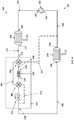
- a heat transfer system 200 is illustrated in FIG. 2 .
- the system 200 may comprise a primary fluid flow path 202 having a primary fluid disposed therein.
- the primary fluid flow path 202 may comprise various components configured to transfer the heat from one location and dispose of it into another. These other components may comprise heat exchanger 204, compressor 206, condenser 208, and thermal energy storage (TES) section 210. These components may be arranged in a loop such that each subsequent component, as listed in the order above, being located downstream of the prior components and the effluent of the TES section 210 being returned to the heat exchanger 204 to complete the loop.
- TES thermal energy storage
- Each of above components forming the primary fluid flow path 202 may be coupled to one another via one or more conduits.
- the outlet 260 of heat exchanger 204 may be coupled to the inlet 262 of compressor 206 via the heat-exchanger-compressor conduit 264; the outlet 266 of compressor 206 may be coupled to the inlet 268 of condenser 208 by the compressor-condenser conduit 270; the outlet 272 of condenser 208 may be coupled to the inlet 274 of TES section 210 by condenser-TES-section conduit 276; and, outlet 278 of TES section 210 may be coupled to the inlet 280 of heat exchanger 204 by a TES-section-heat-exchanger conduit 282.
- Primary fluid flow path 202 may comprise additional components and/or conduits, some of which are described herein.
- the primary fluid flow path 202 may form a closed fluid flow path, meaning that the system 200 is designed such that the primary fluid does not intentionally enter or leave the primary fluid flow path 202 during normal operation. Being characterized as closed does not prohibit, however, primary fluid from being added to or removed from the primary fluid flow path 202 to make up for leaks, change of the primary fluid after fluid degradation, or for some other maintenance or repair procedure.
- the primary fluid disposed with the primary fluid flow path 202 can be any appropriate fluid, vapor or liquid, capable of achieving the desired heat transfer.
- the primary fluid may be water or a refrigerant.
- the particular fluid for system 200 can be dependent upon the heat load and the temperature of the environments/systems that transfer heat into or out of the system 200.
- Heat exchanger 204 may be of suitable type for transferring heat 212 into the primary fluid, which runs in the cold-side channels (or tubes or other appropriate geometry) of heat exchanger 204.
- Heat exchanger 204 may be a heat source or load.
- the hot-side channels may be filled with fluid, e.g., water or air, from the environment/system to be cooled.
- Heat exchanger 204 may be a parallel-flow, cross-flow, multi-pass-flow, or counter-flow heat exchanger.
- heat exchanger 204 is an evaporator that evaporates a portion or all of the primary fluid flowing therein.
- heat exchanger 204 may comprise a series of conduits thermally coupled to a heat source or load that is not a fluid.
- the conduits of heat exchanger 204 may be placed in thermal proximity, contact, or coupling with a solid structure that produces heat such that this heat is transferred into and removed by the primary fluid.
- the heat transfer 212 into the primary fluid in heat exchanger 204 may be a variable load such as heat load 103 as shown in FIG. 1 .
- a variable load 300 is illustrated in FIG. 3 .
- heat load 300 is above its average heat load 303 for only a portion of time.
- a typical heat transfer system would be sized based on the peak heat load 305. This design results in a condenser, compressor, and/or fans that are oversized for all but the peak heat load 305.
- Compressor 206 raises the pressure of the primary fluid. This increase in pressure may be used to provide the workflow required to circulate the primary fluid within the primary fluid flowpath 202. Raising the pressure of the primary fluid may also raise the temperature of the primary fluid, thereby allowing heat to be rejected from the primary fluid in the condenser 208.
- compressor 206 may be a pump configured to raise the pressure of liquid, such as in an absorption system (see FIG. 7 , discussed below).
- Condenser 208 receives the higher-temperature/pressure primary fluid from the compressor 206.
- Condenser 208 may be a heat exchanger that rejects heat 214 from the primary fluid to a heat sink which may be, e.g., the ambient environment.
- Condenser 208 may be a parallel-flow, counter-flow, multi-pass-flow, or cross-flow heat exchanger.
- the primary fluid may run in the hot-side channels of condenser 208.
- the cold-side channels of condenser 208 may be filled with a fluid from the heat sink, e.g., ambient air.
- Condenser 208 may be sized such that the condenser 208 may be insufficient to condense and/or sub cool all of the primary fluid flowing therethrough when heat input 212 and compressor 206 power and heat input is sufficiently larger than heat-out 214 (a person of ordinary skill will recognize that the energy inputted into system 200 must be rejected at some point in order for the system 200 to continue effective operation; as such, heat input 212 can be considered as including additional sources of energy (from, e.g., pump work) even if not expressly stated herein). To accommodate this intermittent, maximum load, system 200 may comprise a TES section 210 to which heat may be temporarily rejected.
- condenser 208 may condense and/or sub cool the primary fluid. This primary fluid is then used to cool, or "recharge,” the thermal capacity of TES section 210.
- the condenser 208 is sized to accommodate the average heat load 303, a heat input above the average 303, as represented by heat-excess area 307, will prevent the condenser from condensing and/or sub cooling the primary fluid. During this period, the supplemental heat capacity of TES section 210 is used to make up for the deficiency of the condenser 208.
- the heat load 300 is less than the average heat load 303, as represented by the area 309 in FIG.
- the condenser 208 has capacity to condense and/or sub cool a portion or all of the primary fluid that may be subsequently used to recharge the TES section 210 (and, in particular, the TES unit 220 as described below) while concurrently rejecting the heat from heat load 212.
- condenser 208 may comprise a force ventilation unit (not shown), such as a fan, that increases the flow rate of the ambient environment fluid over condenser 208.
- the "sizing" of the condenser 208 may factor in the addition of the forced ventilation unit.
- TES section 210 may comprise several components, including pressure regulating valve 216, bypass valve 218, TES unit 220, pressure regulating valve 222, and bypass valve 224.
- TES unit 220 has an inlet 226 and outlet 228.
- Inlet 226 of TES unit 220 is downstream of and coupled to TES section inlet 274 by TES-section-TES-unit-inlet conduit 284.
- Outlet 228 of TES unit 220 is upstream of and coupled to TES section outlet 278 by TES-section-TES-unit-outlet conduit 286.
- the conduits coupling the TES unit 220 to the inlet and/or outlet of the TES section 210 may have various components disposed therein and/or coupled in parallel with all or a portion of the conduits.
- TES unit 220 provides a secondary heat sink for the primary fluid disposed in the primary fluid flow path 202.
- TES unit 220 provides a supplemental heat sink that can condense the remaining vapor of the primary fluid. While heat can be rejected to TES unit 220 to complete this condensing, TES unit 220 may have a limited thermal capacity such that only a limited amount of heat can be rejected to TES unit 220.
- the thermal capacity of TES unit 220 can be sized to match the difference between the average heat load and the maximum heat load over a designed period of time. After the thermal capacity of the TES unit 220 has been exceeded, TES unit 220 must be recharge for subsequent heat loads that exceed the thermal output capacity of condenser 208.
- TES unit 220 examples include phase change materials, chilled water, chilled coolant, two-phase mixtures such as water and ice, or other suitable material.
- TES section 210 may further comprise pressure regulating valve 216, bypass valve 218, pressure regulating valve 222, and bypass valve 224. These components may aid in using TES unit 220 as a heat sink and providing primary fluid to TES unit 220 at a temperature that recharges the thermal capacity of TES unit 220.
- bypass valve 218 is open and bypass valve 224 is shut.
- Primary fluid flowing through valve 218 bypasses pressure regulating valve 216.
- pressure regulating valve 222 maintains the pressure of the primary fluid upstream of pressure regulating valve 222 at saturation pressure through both the condenser 208 and TES unit 220.
- Primary fluid flowing in condenser 208 is partially condensed, and flows through bypass valve 218 to TES unit 220 that completes the condensing process.
- TES unit 220 may sub cool the primary fluid.
- the liquid primary fluid is then expanded across pressure regulating valve 222, dropping the primary fluid temperature prior to the fluid returning to heat exchanger 204.
- pressure regulating valve 216 will regulate the pressure in condenser 208 and pressure regulating valve 222 will regulate pressure in the TES unit 220 independently from one another.
- Pressure regulating valve 216 may be fully open when bypass valve 218 is fully opened. After pressure regulating valve 216 is fully open, pressure regulating valve 222 will regulate the pressure in the condenser 208 and TES unit 220.
- Bypass valve 224 may be shut during this operation.
- the pressure of the primary fluid in the TES unit 220 may be set to maximize heat rejection, target a specific heat duty, or provide a specific amount of sub-cooling at the outlet of TES unit 220.
- the pressure within the condenser 208 may be set to maximize condenser heat rejection, keep the compressor 206 operational, or provide a specified sub-cool at the outlet of the condenser 208.
- the TES unit may be recharge at a maximum rate by operating the system such that bypass valve 218 is shut and bypass valve 224 is opened. With valve 218 shut, pressure regulating valve 216 maintains the primary fluid pressure in the condenser 208 at saturation pressure. The primary fluid is fully condensed, and possibly sub cooled, by the condenser 208. Primary fluid is expanded across pressure regulating valve 216, dropping the temperature of the primary fluid as its heat energy is used to vaporize all or a portion of the primary fluid.
- the lower temperature primary fluid flows through TES unit 220, extracting heat from TES unit 220 when TES unit 220 is at a higher temperature than the primary fluid. This heat transfer recharges the thermal capacity of the TES unit.
- the primary fluid mixture then flows through valve 224, bypassing pressure regulating valve 222, on its way to heat exchanger 204 as a vapor or a vapor-liquid mixture.
- pressure regulating valve 222 may regulate the pressure of the TES unit 220 independently of the pressure in condenser 208. Pressure regulating valve 222 may being to open during this transition. When pressure regulating valve 222 is fully open bypass valve 224 is also fully open. Bypass valve 218 is shut for the duration such that pressure regulating valve 216 is able to regulate the pressure within condenser 208.
- Condenser 208 may also be configured to operate in different modes, e.g., with or without forced ventilation.
- the condenser 208 may be sized such that the average heat load 212 and the compressor 206 power and heat transferred into the primary fluid exceeds the ability of the condenser 208 to reject heat out 214 during a mode where no forced ventilation is provided.
- TES unit 220 may provide the additional heat rejection capacity during such a mode of operation.
- Pressure regulating valves 216 and 222 may be backpressure regulating valves.
- Bypass valves 218 and 224 may be solenoid valves that are operated based on the parameters of the primary fluid (e.g., temperature and pressure, advanced logic control).
- Each pressure regulating valve 216 and 222 and its associated bypass valve 218 and 224, respectively, may be replaced with a single, accurate, fast-acting control valve.
- the replacement valve for pressure regulating valve 222 and bypass 224 may be a diaphragm back pressure regulating valve or a pneumatically driven valve. This replacement valve should be able to handle the primary fluid flow in all states (i.e., vapor, liquid) and accurately control the sub cooling of the primary fluid.
- the saturation pressure and temperature of the TES unit 220 can be regulated thereby regulating the heat transfer rate at the TES unit 220 without impacting the lower-pressure primary fluid downstream of the TES section 210.
- Embodiments in which a bypass valve is connected in parallel with a pressure regulating valve may avoid the pressure drop that may occur across a fully open pressure regulating valve.
- the replacement valve for pressure regulating valve 216 and bypass valve 218 may be a diaphragm-style back-pressure regulating valve, typically pneumatically, spring or electronically controlled valve. This replacement valve should be accurate and fast-acting.
- FIG. 4 a diagram of a heat transfer system 400 is provided in FIG. 4 .
- Heat transfer system 400 is comprised of many of the same components performing the same functions as those described herein elsewhere.
- the primary differences between heat transfer systems 200 and 400 are located within TES sections 210 and 410.
- TES section 410 four-way valves 430 and 486 are disposed in TES section 410 to bypass, utilize, or cool TES unit 220 using conduits 484 and 488 as well as TES cooling fluid conduit 432.
- four-way valve 430 is positioned to direct the liquid, possibly sub cooled, primary fluid from the effluent of condenser 208 to pressure regulating valve 222 via conduit 484 and bypass valve 486.
- pressure regulating valve 222 maintains the pressure in condenser 208 at saturation conditions to ensure that the primary fluid is condensed and/or sub-cooled in condenser 208.
- Primary fluid is expanded across pressure regulating valve 222.
- a portion of the expanded primary fluid is directed through TES cooling fluid conduit 432 and bypass valve 486 to TES unit 220, thereby providing a supply of chilled primary fluid to cool and recharge TES unit 220.
- the fluid flows through bypass valve 430 to the heat-exchanger-compressor conduit 264 via TES cooling fluid conduit 432.
- the portion of fluid that does not flow through TES cooling fluid conduit is provided to the inlet 280 of heat exchanger 204 via the TES-section-heat-exchanger conduit 282.
- four-way valve 430 is positioned to route the effluent of condenser 208 to TES unit 220 via conduit 488.
- the TES unit 220 completes the condensing and/or sub cooling of the primary fluid.
- Fluid is then directed to the pressure regulating valve 222 via bypass valve 486.
- Pressure regulating valve 222 maintains the upstream primary fluid pressure at conditions necessary to promote the required heat transfer.
- the primary fluid is expanded across pressure regulating valve 222 and provided back to heat exchanger 204.
- Four-way valves 430 and/or 486 are positioned to prevent the flow of primary fluid in the TES cooling fluid conduit 432 and conduit 484 during this mode of operation.
- TES cooling fluid conduit 432 is connected between a portion of the TES-section-heat-exchanger conduit 282 and four-way valve 486.
- FIG. 5 illustrate a heat transfer system 500 in accordance with some embodiments.
- Heat transfer system 500 may comprise similar components performing similar functions as described elsewhere herein. It should be understood that many of these components are omitted from FIG. 5 for ease of reading.
- heat transfer system further comprises an accumulator 534 and a pump 536.
- the additional components are combined with the illustrated vapor compression system to form what is called a liquid overfeed system. Further details and embodiments of liquid overfeed systems are provided for in the concurrently filed and related U.S. Application No. ##### entitled "MECHANICALLY PUMPED SYSTEM FOR DIRECT CONTROL OF TWO-PHASE ISOTHERMAL EVAPORATION", Docket Number G3106-00290 / LWA12265, first name inventor: Eugene Jansen. The entirety of which is hereby incorporated by reference.
- Accumulator 534 is located between the effluent of TES section 510 (which may be TES section 210 and/or 410) and the suction of compressor 206.
- the accumulator 534 provides several functions, including at least providing a surge volume of refrigerant for supply to heat exchanger 204, providing pump head for pump 536, and separating the vapor/liquid mixture from the effluent of both the TES section 510 and evaporator 204.
- accumulator 534 has at least two inputs and two outputs. The inputs are from the effluents of the TES section 510 and evaporator 204. The two outputs are from vapor supplied to the compressor 206 and the fluid supplied to pump 536.
- the conduit may be placed downstream of pump 536, thereby coupling the outlet of pump 536 and a valve in the TES section 510, e.g., input of four-way valve 486 of TES section 410.
- Other locations may also serve as the initiating point of TES cooling fluid conduit 532.
- a heat transfer system 600 is illustrated in Fig. 6 .
- Heat transfer system 600 is comprised of many of the same components performing the same functions as those described elsewhere herein. It should be understood that several components of heat transfer system 600 have been omitted for clarity.
- the primary differences between heat transfer systems 200, 400 and 600 are located within TES sections 210, 410 and 610.
- TES section 610 a four-way valve 688 is disposed between the upstream side of both pressure regulating valve 216 and TES unit 220 and the outlet 272 of the condenser 208. Downstream of both pressure regulating valve 216 and TES unit 220 is pressure regulating valve 222.
- TES section 610 comprises a TES unit cooling fluid conduit 932 that is located downstream of pressure regulating valve 222 and fluidically couples this location to an inlet of four-way valve 688.
- TES unit cooling fluid conduit 932 may be coupled to the outlet of pump 536 as shown in Fig. 5 such that accumulator 534 is located within TES-section-heat-exchanger conduit 282 between the outlet 278 and the branch-off point of TES unit cooling fluid conduit 932.
- four-way valve 688 is positioned to direct the liquid, possibly sub cooled, primary fluid from the effluent of condenser 208 to pressure regulating valve 216 via conduit 690.
- pressure regulating valve 216 maintains the pressure in condenser 208 at saturation conditions to ensure that the primary fluid is condensed in condenser 208.
- Primary fluid is expanded across pressure regulating valve 216 and then flows to pressure regulating valve 222, which is fully open and is not maintaining upstream primary fluid pressure.
- a portion of the expanded primary fluid may be directed through TES cooling fluid conduit 932 and the four-way valve 688 to TES unit 220, thereby providing a supply of chilled primary fluid to cool and recharge TES unit 220.
- a pump e.g. pump 536, may supply the pump work require to drive the primary fluid through TES cooling fluid conduit 932.
- the outlet 278 of TES section 610 is coupled to the accumulator 534 at a point upstream of the branch-off of TES cooling fluid conduit 932.
- four-way valve 688 is positioned to route the effluent of condenser 208 to TES unit 220 via conduit 692, bypassing pressure regulating valve 216.
- the TES unit 220 completes the condensing and/or sub cooling of the primary fluid.
- Pressure regulating valve 222 maintains the upstream primary fluid pressure at conditions necessary to transfer the required heat.
- the primary fluid is expanded across pressure regulating valve 222 and provided back to heat exchanger 204.
- Four-way valve 688 is positioned to prevent the flow of primary fluid in the TES cooling fluid conduit 932 during this mode of operation.
- a heat transfer system 700 is illustrated in Fig. 7 .
- System 700 may comprise many of the same components that perform the same functions as described above.
- System 700 differs from those disclosed in that it does not contain a vapor compression loop. Rather, system 700 is an adsorption system that comprises absorber 794, pump 796, generator 798, and valve 7100.
- Primary fluid from heat exchanger 204 is provided to absorber 794 wherein the primary fluid is absorbed into an absorbent while heat is rejected.
- the absorbent / primary fluid mixture is sent via pump 796 to generator 798.
- Generator 798 heat is provided to the generator, thereby releasing the absorbed primary fluid for flow to condenser 208, TES section 210, and then returning to heat exchanger 204.
- Absorbent is allowed to return to the absorbed 794 via valve 7100, which also functions to maintain a pressure differential between generator 798 and absorber 794.
- TES section 210 While the above illustrated system 700 utilizes TES section 210, it should be understood that this absorption system may also utilize TES section 410, 510, or 610 and their manner of interfacing with the rest of the systems disclosed above.
Landscapes
- Engineering & Computer Science (AREA)
- Physics & Mathematics (AREA)
- Mechanical Engineering (AREA)
- Thermal Sciences (AREA)
- General Engineering & Computer Science (AREA)
- Chemical & Material Sciences (AREA)
- Combustion & Propulsion (AREA)
- Other Air-Conditioning Systems (AREA)
- Compression-Type Refrigeration Machines With Reversible Cycles (AREA)
Applications Claiming Priority (1)
| Application Number | Priority Date | Filing Date | Title |
|---|---|---|---|
| US16/380,665 US10921042B2 (en) | 2019-04-10 | 2019-04-10 | Method for reducing condenser size and power on a heat rejection system |
Publications (3)
| Publication Number | Publication Date |
|---|---|
| EP3722704A2 true EP3722704A2 (de) | 2020-10-14 |
| EP3722704A3 EP3722704A3 (de) | 2021-01-13 |
| EP3722704B1 EP3722704B1 (de) | 2025-12-31 |
Family
ID=70058125
Family Applications (1)
| Application Number | Title | Priority Date | Filing Date |
|---|---|---|---|
| EP20166551.0A Active EP3722704B1 (de) | 2019-04-10 | 2020-03-30 | Verfahren zur reduzierung der kondensatorgrösse und -leistung auf einem wärmeabweisungssystem |
Country Status (3)
| Country | Link |
|---|---|
| US (1) | US10921042B2 (de) |
| EP (1) | EP3722704B1 (de) |
| CA (1) | CA3077991A1 (de) |
Families Citing this family (12)
| Publication number | Priority date | Publication date | Assignee | Title |
|---|---|---|---|---|
| US11162388B1 (en) | 2020-08-12 | 2021-11-02 | Rolls-Royce North American Technologies Inc. | Thermal management system to cool transient heat loads with low power consumption |
| US11754324B2 (en) * | 2020-09-14 | 2023-09-12 | Copeland Lp | Refrigerant isolation using a reversing valve |
| US11761712B2 (en) | 2020-09-24 | 2023-09-19 | Rolls-Royce North American Technologies Inc. | Method of controlling thermal energy storage in a thermal energy management system |
| US11530844B2 (en) | 2020-09-30 | 2022-12-20 | Rolls-Royce North American Technologies Inc. | System for supporting intermittent fast transient heat loads |
| US11940188B2 (en) | 2021-03-23 | 2024-03-26 | Copeland Lp | Hybrid heat-pump system |
| US12196462B2 (en) | 2021-03-23 | 2025-01-14 | Copeland Lp | Heat-pump system with multiway valve |
| US11959669B2 (en) | 2021-05-06 | 2024-04-16 | Rolls-Royce North American Technologies Inc. | Bimodal cooling system |
| US12108571B2 (en) | 2021-05-06 | 2024-10-01 | Rolls-Royce North American Technologies Inc. | Electronics cabinet cooling system |
| US12351337B2 (en) * | 2021-11-19 | 2025-07-08 | General Electric Company | Sub-coolers for refueling onboard cryogenic fuel tanks and methods for operating the same |
| JP7716821B2 (ja) * | 2022-03-29 | 2025-08-01 | 東芝エネルギーシステムズ株式会社 | 蓄熱発電システムおよび蓄熱装置 |
| US20240151411A1 (en) * | 2022-11-04 | 2024-05-09 | Jayvic, Inc. | Thermal Liquid Battery |
| US12460874B2 (en) | 2023-08-03 | 2025-11-04 | United States Of America As Represented By The Secretary Of The Air Force | Two-phase refrigerant pump bladder control system |
Family Cites Families (39)
| Publication number | Priority date | Publication date | Assignee | Title |
|---|---|---|---|---|
| US3091944A (en) | 1961-10-31 | 1963-06-04 | Trane Co | Heat pump system |
| GB1532542A (en) | 1975-01-14 | 1978-11-15 | Awalt T | Hot or cold storage system |
| US4175399A (en) | 1977-02-18 | 1979-11-27 | The Rovac Corporation | Closed loop air conditioning system having automatic pressurizing means for variation of heat rate |
| US4333316A (en) | 1980-10-14 | 1982-06-08 | General Electric Company | Automatic control apparatus for a heat pump system |
| JPS57175858A (en) | 1981-04-23 | 1982-10-28 | Mitsubishi Electric Corp | Air conditionor |
| DE3610332A1 (de) | 1985-03-30 | 1986-10-09 | Kabushiki Kaisha Toshiba, Kawasaki, Kanagawa | Regenerativheizgeraet |
| US4934155A (en) | 1986-03-18 | 1990-06-19 | Mydax, Inc. | Refrigeration system |
| EP0449641B1 (de) | 1990-03-30 | 1995-05-10 | Mitsubishi Denki Kabushiki Kaisha | Klimaanlage |
| JPH0651756U (ja) | 1992-12-16 | 1994-07-15 | 株式会社東洋製作所 | 冷却装置 |
| US5353602A (en) | 1993-03-25 | 1994-10-11 | Calmac Manufacturing Corporation | Non-steady-state self-regulating intermittent flow thermodynamic system |
| US5678626A (en) * | 1994-08-19 | 1997-10-21 | Lennox Industries Inc. | Air conditioning system with thermal energy storage and load leveling capacity |
| NO20005576D0 (no) | 2000-09-01 | 2000-11-03 | Sinvent As | Reversibel fordampningsprosess |
| DE102004037417B3 (de) | 2004-07-30 | 2006-01-19 | Siemens Ag | Verfahren und Vorrichtung zur Übertragung von Wärme von einer Wärmequelle an einen thermodynamischen Kreislauf mit einem Arbeitsmittel mit zumindest zwei Stoffen mit nicht-isothermer Verdampfung und Kondensation |
| WO2007121540A2 (en) | 2006-04-20 | 2007-11-01 | Springer Carrier Ltda | Heat pump system having auxiliary water heating and heat exchanger bypass |
| US7584628B2 (en) | 2006-06-29 | 2009-09-08 | Northrop Grumman Corporation | System for delivering coolant to a laser system |
| US7648598B2 (en) | 2006-10-23 | 2010-01-19 | National Central University | Manufacturing method for isothermal evaporation casting process |
| US9989280B2 (en) | 2008-05-02 | 2018-06-05 | Heatcraft Refrigeration Products Llc | Cascade cooling system with intercycle cooling or additional vapor condensation cycle |
| WO2010003590A2 (en) | 2008-07-07 | 2010-01-14 | Carrier Corporation | Refrigeration circuit |
| FR2950423B1 (fr) | 2009-09-22 | 2012-11-16 | Valeo Systemes Thermiques | Dispositif de conditionnement d'air pour une installation de chauffage,ventilation et/ou climatisation. |
| WO2011150314A2 (en) | 2010-05-27 | 2011-12-01 | Xdx Innovative Refrigeration, Llc | Surged heat pump systems |
| DE102010026648B4 (de) | 2010-07-09 | 2015-12-31 | Gea Grasso Gmbh | Kälteanlage zur Kühlung eines Containers |
| US8783052B2 (en) | 2010-11-04 | 2014-07-22 | International Business Machines Corporation | Coolant-buffered, vapor-compression refrigeration with thermal storage and compressor cycling |
| JP5445472B2 (ja) | 2011-01-13 | 2014-03-19 | 株式会社東洋製作所 | 冷凍システム |
| JP2014509728A (ja) * | 2011-04-01 | 2014-04-21 | アイス エナジー インコーポレーテッド | 統合マルチモード蓄熱式冷媒回路 |
| WO2012147367A1 (ja) | 2011-04-28 | 2012-11-01 | パナソニック株式会社 | 冷凍装置 |
| JP2014520244A (ja) * | 2011-06-17 | 2014-08-21 | アイス エナジー テクノロジーズ インコーポレーテッド | 液体−吸入の熱交換による熱エネルギー貯蔵のためのシステム及び方法 |
| JP6087359B2 (ja) | 2011-09-09 | 2017-03-01 | セルン − ヨーロピアン オーガナイゼーション フォー ニュークリア リサーチCERN − European Organization for Nuclear Research | 正確な温度制御のための小型冷却システムおよび方法 |
| JP2013061099A (ja) | 2011-09-12 | 2013-04-04 | Toyota Motor Corp | 熱交換装置および熱交換装置の制御方法 |
| US20150292775A1 (en) | 2012-10-25 | 2015-10-15 | Carrier Corporation | Refrigeration system with phase change material |
| US20160201931A1 (en) * | 2013-08-29 | 2016-07-14 | Carrier Corporation | Thermal energy storage assembly with phase change materials |
| JP6464502B2 (ja) | 2013-10-24 | 2019-02-06 | パナソニックIpマネジメント株式会社 | 冷凍サイクル装置 |
| WO2016004257A1 (en) | 2014-07-01 | 2016-01-07 | Evapco, Inc. | Evaporator liquid preheater for reducing refrigerant charge |
| JP6495053B2 (ja) | 2015-03-03 | 2019-04-03 | 三菱重工業株式会社 | 冷凍システム、冷凍システムの運転方法及び冷凍システムの設計方法 |
| WO2017022378A1 (ja) | 2015-08-03 | 2017-02-09 | 株式会社デンソー | 統合弁 |
| JP6481668B2 (ja) | 2015-12-10 | 2019-03-13 | 株式会社デンソー | 冷凍サイクル装置 |
| US20170292770A1 (en) | 2016-04-07 | 2017-10-12 | Hussmann Corporation | Refrigeration system with fluid defrost |
| JP6642247B2 (ja) | 2016-04-28 | 2020-02-05 | 株式会社デンソー | 冷凍サイクル装置 |
| GB201610977D0 (en) | 2016-06-23 | 2016-08-10 | Sunamp Ltd | A thermal energy storage system |
| US10168058B2 (en) | 2017-03-16 | 2019-01-01 | Therma-Stor LLC | Dehumidifier with secondary evaporator and condenser coils |
-
2019
- 2019-04-10 US US16/380,665 patent/US10921042B2/en active Active
-
2020
- 2020-03-30 EP EP20166551.0A patent/EP3722704B1/de active Active
- 2020-04-09 CA CA3077991A patent/CA3077991A1/en active Pending
Also Published As
| Publication number | Publication date |
|---|---|
| US20200326113A1 (en) | 2020-10-15 |
| EP3722704B1 (de) | 2025-12-31 |
| EP3722704A3 (de) | 2021-01-13 |
| CA3077991A1 (en) | 2020-10-10 |
| US10921042B2 (en) | 2021-02-16 |
Similar Documents
| Publication | Publication Date | Title |
|---|---|---|
| EP3722704B1 (de) | Verfahren zur reduzierung der kondensatorgrösse und -leistung auf einem wärmeabweisungssystem | |
| EP3722705A2 (de) | Verfahren zur reduzierung der kondensatorgrösse und -leistung auf einem wärmeabweisungssystem | |
| US11744042B2 (en) | Thermal management system with dual-use serial thermal energy storage for system size reduction | |
| EP2889551B1 (de) | Transkritische Mehrfachverdampferkühlsysteme | |
| US11796226B2 (en) | System for supporting intermittent fast transient heat loads | |
| CN107178833B (zh) | 热回收外机系统和空调系统 | |
| US11761712B2 (en) | Method of controlling thermal energy storage in a thermal energy management system | |
| EP2751499B1 (de) | Kühlsystem und kühlverfahren mit wärmerückgewinnung | |
| JP2007198693A (ja) | カスケード型ヒートポンプシステム | |
| US20210364208A1 (en) | Heating, Ventilation, and Air-Conditioning System with a Thermal Energy Storage Device | |
| US20140196489A1 (en) | Energy-optimized cycle control of time-variant loads for thermal management of vapor compression systems | |
| EP2918950A1 (de) | Motorgetriebener wärmepumpenkühler | |
| US11892203B2 (en) | Method of operating refrigeration cycle device | |
| US10571156B2 (en) | Self-regulating valve for a vapour compression system | |
| CN119353805A (zh) | 大温跨精确冷热循环系统及其控制方法 | |
| US20240011690A1 (en) | Refrigeration system with heat pump compression | |
| CN109210814B (zh) | 一种多功能制冷系统 | |
| JP2004144411A (ja) | 空気調和設備 | |
| CN219976620U (zh) | 蓄冷空调系统及空调器 | |
| CN213335032U (zh) | 一种制冷系统 | |
| CN222964031U (zh) | 空调系统 | |
| CN115638557B (zh) | 一种基于多喷射器装置的多温区冰箱系统及工作方法 | |
| JP2001280729A (ja) | 冷凍装置 | |
| CN216204499U (zh) | 一种带双级压缩循环切换的制冷系统 | |
| CN100427855C (zh) | 冷冻系统和该冷冻系统的控制方法 |
Legal Events
| Date | Code | Title | Description |
|---|---|---|---|
| PUAI | Public reference made under article 153(3) epc to a published international application that has entered the european phase |
Free format text: ORIGINAL CODE: 0009012 |
|
| STAA | Information on the status of an ep patent application or granted ep patent |
Free format text: STATUS: THE APPLICATION HAS BEEN PUBLISHED |
|
| AK | Designated contracting states |
Kind code of ref document: A2 Designated state(s): AL AT BE BG CH CY CZ DE DK EE ES FI FR GB GR HR HU IE IS IT LI LT LU LV MC MK MT NL NO PL PT RO RS SE SI SK SM TR |
|
| AX | Request for extension of the european patent |
Extension state: BA ME |
|
| PUAL | Search report despatched |
Free format text: ORIGINAL CODE: 0009013 |
|
| AK | Designated contracting states |
Kind code of ref document: A3 Designated state(s): AL AT BE BG CH CY CZ DE DK EE ES FI FR GB GR HR HU IE IS IT LI LT LU LV MC MK MT NL NO PL PT RO RS SE SI SK SM TR |
|
| AX | Request for extension of the european patent |
Extension state: BA ME |
|
| RIC1 | Information provided on ipc code assigned before grant |
Ipc: F25B 49/02 20060101ALI20201207BHEP Ipc: F25B 6/04 20060101AFI20201207BHEP Ipc: F25B 41/06 20060101ALI20201207BHEP Ipc: F25B 40/02 20060101ALI20201207BHEP Ipc: F28D 20/00 20060101ALI20201207BHEP Ipc: F25B 41/04 20060101ALI20201207BHEP Ipc: F25B 25/00 20060101ALI20201207BHEP Ipc: F25B 7/00 20060101ALI20201207BHEP Ipc: F25B 5/02 20060101ALI20201207BHEP |
|
| STAA | Information on the status of an ep patent application or granted ep patent |
Free format text: STATUS: REQUEST FOR EXAMINATION WAS MADE |
|
| 17P | Request for examination filed |
Effective date: 20210615 |
|
| RBV | Designated contracting states (corrected) |
Designated state(s): AL AT BE BG CH CY CZ DE DK EE ES FI FR GB GR HR HU IE IS IT LI LT LU LV MC MK MT NL NO PL PT RO RS SE SI SK SM TR |
|
| STAA | Information on the status of an ep patent application or granted ep patent |
Free format text: STATUS: EXAMINATION IS IN PROGRESS |
|
| 17Q | First examination report despatched |
Effective date: 20240411 |
|
| GRAP | Despatch of communication of intention to grant a patent |
Free format text: ORIGINAL CODE: EPIDOSNIGR1 |
|
| STAA | Information on the status of an ep patent application or granted ep patent |
Free format text: STATUS: GRANT OF PATENT IS INTENDED |
|
| RIC1 | Information provided on ipc code assigned before grant |
Ipc: F25B 6/04 20060101AFI20250811BHEP Ipc: F25B 40/02 20060101ALI20250811BHEP Ipc: F28D 20/00 20060101ALI20250811BHEP Ipc: F25B 49/02 20060101ALI20250811BHEP Ipc: F25B 7/00 20060101ALI20250811BHEP Ipc: F25B 25/00 20060101ALI20250811BHEP Ipc: F25B 5/02 20060101ALI20250811BHEP |
|
| INTG | Intention to grant announced |
Effective date: 20250911 |
|
| GRAS | Grant fee paid |
Free format text: ORIGINAL CODE: EPIDOSNIGR3 |
|
| GRAA | (expected) grant |
Free format text: ORIGINAL CODE: 0009210 |
|
| STAA | Information on the status of an ep patent application or granted ep patent |
Free format text: STATUS: THE PATENT HAS BEEN GRANTED |
|
| AK | Designated contracting states |
Kind code of ref document: B1 Designated state(s): AL AT BE BG CH CY CZ DE DK EE ES FI FR GB GR HR HU IE IS IT LI LT LU LV MC MK MT NL NO PL PT RO RS SE SI SK SM TR |
|
| REG | Reference to a national code |
Ref country code: CH Ref legal event code: F10 Free format text: ST27 STATUS EVENT CODE: U-0-0-F10-F00 (AS PROVIDED BY THE NATIONAL OFFICE) Effective date: 20251231 Ref country code: GB Ref legal event code: FG4D |
|
| REG | Reference to a national code |
Ref country code: DE Ref legal event code: R096 Ref document number: 602020064642 Country of ref document: DE |
|
| P01 | Opt-out of the competence of the unified patent court (upc) registered |
Free format text: CASE NUMBER: UPC_APP_0015145_3722704/2025 Effective date: 20251128 |
|
| REG | Reference to a national code |
Ref country code: IE Ref legal event code: FG4D |
|
| REG | Reference to a national code |
Ref country code: LT Ref legal event code: MG9D |
|
| PG25 | Lapsed in a contracting state [announced via postgrant information from national office to epo] |
Ref country code: NO Free format text: LAPSE BECAUSE OF FAILURE TO SUBMIT A TRANSLATION OF THE DESCRIPTION OR TO PAY THE FEE WITHIN THE PRESCRIBED TIME-LIMIT Effective date: 20260331 |
|
| PG25 | Lapsed in a contracting state [announced via postgrant information from national office to epo] |
Ref country code: FI Free format text: LAPSE BECAUSE OF FAILURE TO SUBMIT A TRANSLATION OF THE DESCRIPTION OR TO PAY THE FEE WITHIN THE PRESCRIBED TIME-LIMIT Effective date: 20251231 Ref country code: HR Free format text: LAPSE BECAUSE OF FAILURE TO SUBMIT A TRANSLATION OF THE DESCRIPTION OR TO PAY THE FEE WITHIN THE PRESCRIBED TIME-LIMIT Effective date: 20251231 |
|
| PG25 | Lapsed in a contracting state [announced via postgrant information from national office to epo] |
Ref country code: RS Free format text: LAPSE BECAUSE OF FAILURE TO SUBMIT A TRANSLATION OF THE DESCRIPTION OR TO PAY THE FEE WITHIN THE PRESCRIBED TIME-LIMIT Effective date: 20260331 |
|
| PGFP | Annual fee paid to national office [announced via postgrant information from national office to epo] |
Ref country code: FR Payment date: 20260323 Year of fee payment: 7 |
|
| PG25 | Lapsed in a contracting state [announced via postgrant information from national office to epo] |
Ref country code: LV Free format text: LAPSE BECAUSE OF FAILURE TO SUBMIT A TRANSLATION OF THE DESCRIPTION OR TO PAY THE FEE WITHIN THE PRESCRIBED TIME-LIMIT Effective date: 20251231 |