EP3722640B1 - Drive unit - Google Patents
Drive unit Download PDFInfo
- Publication number
- EP3722640B1 EP3722640B1 EP20167947.9A EP20167947A EP3722640B1 EP 3722640 B1 EP3722640 B1 EP 3722640B1 EP 20167947 A EP20167947 A EP 20167947A EP 3722640 B1 EP3722640 B1 EP 3722640B1
- Authority
- EP
- European Patent Office
- Prior art keywords
- torque converter
- prime mover
- torque
- drive unit
- output shaft
- Prior art date
- Legal status (The legal status is an assumption and is not a legal conclusion. Google has not performed a legal analysis and makes no representation as to the accuracy of the status listed.)
- Active
Links
- 230000007246 mechanism Effects 0.000 claims description 35
- 230000005540 biological transmission Effects 0.000 claims description 27
- 239000003638 chemical reducing agent Substances 0.000 claims description 25
- 230000037361 pathway Effects 0.000 description 56
- 239000012530 fluid Substances 0.000 description 35
- 238000001816 cooling Methods 0.000 description 33
- 230000002093 peripheral effect Effects 0.000 description 19
- 230000017525 heat dissipation Effects 0.000 description 7
- 230000004048 modification Effects 0.000 description 7
- 238000012986 modification Methods 0.000 description 7
- 238000010586 diagram Methods 0.000 description 5
- 239000002783 friction material Substances 0.000 description 5
- FYYHWMGAXLPEAU-UHFFFAOYSA-N Magnesium Chemical compound [Mg] FYYHWMGAXLPEAU-UHFFFAOYSA-N 0.000 description 2
- XAGFODPZIPBFFR-UHFFFAOYSA-N aluminium Chemical compound [Al] XAGFODPZIPBFFR-UHFFFAOYSA-N 0.000 description 2
- 229910052782 aluminium Inorganic materials 0.000 description 2
- 238000002485 combustion reaction Methods 0.000 description 2
- 239000010720 hydraulic oil Substances 0.000 description 2
- 229910052749 magnesium Inorganic materials 0.000 description 2
- 239000011777 magnesium Substances 0.000 description 2
- 239000000463 material Substances 0.000 description 2
- 238000004804 winding Methods 0.000 description 2
- RYGMFSIKBFXOCR-UHFFFAOYSA-N Copper Chemical compound [Cu] RYGMFSIKBFXOCR-UHFFFAOYSA-N 0.000 description 1
- 230000009471 action Effects 0.000 description 1
- 230000008859 change Effects 0.000 description 1
- 230000008867 communication pathway Effects 0.000 description 1
- 229910052802 copper Inorganic materials 0.000 description 1
- 239000010949 copper Substances 0.000 description 1
- 230000001419 dependent effect Effects 0.000 description 1
- 230000002708 enhancing effect Effects 0.000 description 1
- 238000009434 installation Methods 0.000 description 1
- 230000009467 reduction Effects 0.000 description 1
- 239000007787 solid Substances 0.000 description 1
Images


Classifications
-
- F—MECHANICAL ENGINEERING; LIGHTING; HEATING; WEAPONS; BLASTING
- F16—ENGINEERING ELEMENTS AND UNITS; GENERAL MEASURES FOR PRODUCING AND MAINTAINING EFFECTIVE FUNCTIONING OF MACHINES OR INSTALLATIONS; THERMAL INSULATION IN GENERAL
- F16H—GEARING
- F16H47/00—Combinations of mechanical gearing with fluid clutches or fluid gearing
- F16H47/06—Combinations of mechanical gearing with fluid clutches or fluid gearing the fluid gearing being of the hydrokinetic type
- F16H47/08—Combinations of mechanical gearing with fluid clutches or fluid gearing the fluid gearing being of the hydrokinetic type the mechanical gearing being of the type with members having orbital motion
-
- B—PERFORMING OPERATIONS; TRANSPORTING
- B60—VEHICLES IN GENERAL
- B60K—ARRANGEMENT OR MOUNTING OF PROPULSION UNITS OR OF TRANSMISSIONS IN VEHICLES; ARRANGEMENT OR MOUNTING OF PLURAL DIVERSE PRIME-MOVERS IN VEHICLES; AUXILIARY DRIVES FOR VEHICLES; INSTRUMENTATION OR DASHBOARDS FOR VEHICLES; ARRANGEMENTS IN CONNECTION WITH COOLING, AIR INTAKE, GAS EXHAUST OR FUEL SUPPLY OF PROPULSION UNITS IN VEHICLES
- B60K1/00—Arrangement or mounting of electrical propulsion units
-
- B—PERFORMING OPERATIONS; TRANSPORTING
- B60—VEHICLES IN GENERAL
- B60K—ARRANGEMENT OR MOUNTING OF PROPULSION UNITS OR OF TRANSMISSIONS IN VEHICLES; ARRANGEMENT OR MOUNTING OF PLURAL DIVERSE PRIME-MOVERS IN VEHICLES; AUXILIARY DRIVES FOR VEHICLES; INSTRUMENTATION OR DASHBOARDS FOR VEHICLES; ARRANGEMENTS IN CONNECTION WITH COOLING, AIR INTAKE, GAS EXHAUST OR FUEL SUPPLY OF PROPULSION UNITS IN VEHICLES
- B60K17/00—Arrangement or mounting of transmissions in vehicles
- B60K17/04—Arrangement or mounting of transmissions in vehicles characterised by arrangement, location, or kind of gearing
- B60K17/043—Transmission unit disposed in on near the vehicle wheel, or between the differential gear unit and the wheel
- B60K17/046—Transmission unit disposed in on near the vehicle wheel, or between the differential gear unit and the wheel with planetary gearing having orbital motion
-
- B—PERFORMING OPERATIONS; TRANSPORTING
- B60—VEHICLES IN GENERAL
- B60K—ARRANGEMENT OR MOUNTING OF PROPULSION UNITS OR OF TRANSMISSIONS IN VEHICLES; ARRANGEMENT OR MOUNTING OF PLURAL DIVERSE PRIME-MOVERS IN VEHICLES; AUXILIARY DRIVES FOR VEHICLES; INSTRUMENTATION OR DASHBOARDS FOR VEHICLES; ARRANGEMENTS IN CONNECTION WITH COOLING, AIR INTAKE, GAS EXHAUST OR FUEL SUPPLY OF PROPULSION UNITS IN VEHICLES
- B60K17/00—Arrangement or mounting of transmissions in vehicles
- B60K17/04—Arrangement or mounting of transmissions in vehicles characterised by arrangement, location, or kind of gearing
- B60K17/14—Arrangement or mounting of transmissions in vehicles characterised by arrangement, location, or kind of gearing the motor of fluid or electric gearing being disposed in or adjacent to traction wheel
-
- B—PERFORMING OPERATIONS; TRANSPORTING
- B60—VEHICLES IN GENERAL
- B60K—ARRANGEMENT OR MOUNTING OF PROPULSION UNITS OR OF TRANSMISSIONS IN VEHICLES; ARRANGEMENT OR MOUNTING OF PLURAL DIVERSE PRIME-MOVERS IN VEHICLES; AUXILIARY DRIVES FOR VEHICLES; INSTRUMENTATION OR DASHBOARDS FOR VEHICLES; ARRANGEMENTS IN CONNECTION WITH COOLING, AIR INTAKE, GAS EXHAUST OR FUEL SUPPLY OF PROPULSION UNITS IN VEHICLES
- B60K17/00—Arrangement or mounting of transmissions in vehicles
- B60K17/26—Arrangement or mounting of transmissions in vehicles characterised by arrangement, location, of type of freewheel device
-
- F—MECHANICAL ENGINEERING; LIGHTING; HEATING; WEAPONS; BLASTING
- F16—ENGINEERING ELEMENTS AND UNITS; GENERAL MEASURES FOR PRODUCING AND MAINTAINING EFFECTIVE FUNCTIONING OF MACHINES OR INSTALLATIONS; THERMAL INSULATION IN GENERAL
- F16H—GEARING
- F16H41/00—Rotary fluid gearing of the hydrokinetic type
- F16H41/24—Details
- F16H41/30—Details relating to venting, lubrication, cooling, circulation of the cooling medium
-
- B—PERFORMING OPERATIONS; TRANSPORTING
- B60—VEHICLES IN GENERAL
- B60K—ARRANGEMENT OR MOUNTING OF PROPULSION UNITS OR OF TRANSMISSIONS IN VEHICLES; ARRANGEMENT OR MOUNTING OF PLURAL DIVERSE PRIME-MOVERS IN VEHICLES; AUXILIARY DRIVES FOR VEHICLES; INSTRUMENTATION OR DASHBOARDS FOR VEHICLES; ARRANGEMENTS IN CONNECTION WITH COOLING, AIR INTAKE, GAS EXHAUST OR FUEL SUPPLY OF PROPULSION UNITS IN VEHICLES
- B60K1/00—Arrangement or mounting of electrical propulsion units
- B60K2001/001—Arrangement or mounting of electrical propulsion units one motor mounted on a propulsion axle for rotating right and left wheels of this axle
-
- B—PERFORMING OPERATIONS; TRANSPORTING
- B60—VEHICLES IN GENERAL
- B60Y—INDEXING SCHEME RELATING TO ASPECTS CROSS-CUTTING VEHICLE TECHNOLOGY
- B60Y2200/00—Type of vehicle
- B60Y2200/90—Vehicles comprising electric prime movers
- B60Y2200/91—Electric vehicles
-
- B—PERFORMING OPERATIONS; TRANSPORTING
- B60—VEHICLES IN GENERAL
- B60Y—INDEXING SCHEME RELATING TO ASPECTS CROSS-CUTTING VEHICLE TECHNOLOGY
- B60Y2306/00—Other features of vehicle sub-units
- B60Y2306/05—Cooling
-
- F—MECHANICAL ENGINEERING; LIGHTING; HEATING; WEAPONS; BLASTING
- F16—ENGINEERING ELEMENTS AND UNITS; GENERAL MEASURES FOR PRODUCING AND MAINTAINING EFFECTIVE FUNCTIONING OF MACHINES OR INSTALLATIONS; THERMAL INSULATION IN GENERAL
- F16D—COUPLINGS FOR TRANSMITTING ROTATION; CLUTCHES; BRAKES
- F16D41/00—Freewheels or freewheel clutches
-
- F—MECHANICAL ENGINEERING; LIGHTING; HEATING; WEAPONS; BLASTING
- F16—ENGINEERING ELEMENTS AND UNITS; GENERAL MEASURES FOR PRODUCING AND MAINTAINING EFFECTIVE FUNCTIONING OF MACHINES OR INSTALLATIONS; THERMAL INSULATION IN GENERAL
- F16H—GEARING
- F16H45/00—Combinations of fluid gearings for conveying rotary motion with couplings or clutches
- F16H45/02—Combinations of fluid gearings for conveying rotary motion with couplings or clutches with mechanical clutches for bridging a fluid gearing of the hydrokinetic type
- F16H2045/0273—Combinations of fluid gearings for conveying rotary motion with couplings or clutches with mechanical clutches for bridging a fluid gearing of the hydrokinetic type characterised by the type of the friction surface of the lock-up clutch
- F16H2045/0278—Combinations of fluid gearings for conveying rotary motion with couplings or clutches with mechanical clutches for bridging a fluid gearing of the hydrokinetic type characterised by the type of the friction surface of the lock-up clutch comprising only two co-acting friction surfaces
-
- F—MECHANICAL ENGINEERING; LIGHTING; HEATING; WEAPONS; BLASTING
- F16—ENGINEERING ELEMENTS AND UNITS; GENERAL MEASURES FOR PRODUCING AND MAINTAINING EFFECTIVE FUNCTIONING OF MACHINES OR INSTALLATIONS; THERMAL INSULATION IN GENERAL
- F16H—GEARING
- F16H2200/00—Transmissions for multiple ratios
- F16H2200/0021—Transmissions for multiple ratios specially adapted for electric vehicles
-
- F—MECHANICAL ENGINEERING; LIGHTING; HEATING; WEAPONS; BLASTING
- F16—ENGINEERING ELEMENTS AND UNITS; GENERAL MEASURES FOR PRODUCING AND MAINTAINING EFFECTIVE FUNCTIONING OF MACHINES OR INSTALLATIONS; THERMAL INSULATION IN GENERAL
- F16H—GEARING
- F16H2200/00—Transmissions for multiple ratios
- F16H2200/20—Transmissions using gears with orbital motion
- F16H2200/2002—Transmissions using gears with orbital motion characterised by the number of sets of orbital gears
- F16H2200/2005—Transmissions using gears with orbital motion characterised by the number of sets of orbital gears with one sets of orbital gears
-
- F—MECHANICAL ENGINEERING; LIGHTING; HEATING; WEAPONS; BLASTING
- F16—ENGINEERING ELEMENTS AND UNITS; GENERAL MEASURES FOR PRODUCING AND MAINTAINING EFFECTIVE FUNCTIONING OF MACHINES OR INSTALLATIONS; THERMAL INSULATION IN GENERAL
- F16H—GEARING
- F16H2200/00—Transmissions for multiple ratios
- F16H2200/20—Transmissions using gears with orbital motion
- F16H2200/2079—Transmissions using gears with orbital motion using freewheel type mechanisms, e.g. freewheel clutches
- F16H2200/2082—Transmissions using gears with orbital motion using freewheel type mechanisms, e.g. freewheel clutches one freewheel mechanisms
-
- F—MECHANICAL ENGINEERING; LIGHTING; HEATING; WEAPONS; BLASTING
- F16—ENGINEERING ELEMENTS AND UNITS; GENERAL MEASURES FOR PRODUCING AND MAINTAINING EFFECTIVE FUNCTIONING OF MACHINES OR INSTALLATIONS; THERMAL INSULATION IN GENERAL
- F16H—GEARING
- F16H47/00—Combinations of mechanical gearing with fluid clutches or fluid gearing
- F16H47/06—Combinations of mechanical gearing with fluid clutches or fluid gearing the fluid gearing being of the hydrokinetic type
Definitions
- the present invention relates to a drive unit for a vehicle.
- JP H04 208643 A discloses a power train structure for a car comprising an internal combustion engine aligned in the car cross direction.
- a speed change gear is arranged crosswise in parallel with a crankshaft of the engine.
- a torque converter is arranged aside of the engine.
- JP H03 262726 A discloses a power plant structure having an internal combustion engine, a transmission and a final reduction device.
- a torque converter is arranged on the opposite side of the engine with respect to the transmission.
- Japan Laid-open Patent Application Publication No. 2013-60996 and US 2019/092157 A1 disclose electric cars having an electric motor as prime mover. In well-known electric cars, a torque, outputted from a motor, is transmitted to drive wheels through a reducer and a differential gear.
- US 2019/092157 A1 (which forms the basis for the preamble of claim 1) discloses an electric car with an electric motor, a torque converter and a power transmission mechanism.
- JP 2001 287556 A discloses a dive unit having two power transmission mechanisms. One power transmission mechanism is is directly connected to an output shaft of an electric motor. The output shaft of the electric motor is further connected to the outer shell of a torque converter, another power transmission mechanism is disposed at the other end of the torque converter and receives torque outputted from the torque converter.
- a drive unit includes a prime mover, a torque converter and a power transmission mechanism.
- the prime mover is an electric motor.
- the torque converter is a component to which a torque is inputted from the prime mover.
- the power transmission mechanism is disposed between the prime mover and the torque converter. Besides, the power transmission mechanism transmits the torque outputted from the torque converter therethrough toward a drive wheel.
- the torque converter amplifies the torque inputted thereto from the prime mover and outputs the amplified torque to the power transmission mechanism.
- the torque converter is normally disposed between the prime mover and the power transmission mechanism.
- the power transmission mechanism is disposed between the prime mover and the torque converter. In other words, attaching the torque converter is enabled without greatly changing the layout of the prime mover and the power transmission mechanism in well-known electric cars.
- the prime mover is disposed on one side of the power transmission mechanism, whereas an unused space exists on the other side of the power transmission mechanism. Because of this, the unused space can be effectively utilized for disposing the torque converter in the present invention.
- the power transmission mechanism is a reducer.
- the drive unit further includes an output shaft and an input shaft.
- the output shaft outputs the torque outputted from the torque converter.
- the input shaft extends from the prime mover and inputs the torque from the prime mover therethrough to the torque converter.
- the output shaft extends from the torque converter toward the prime mover.
- the output shaft has a cylindrical shape.
- the input shaft extends in an interior of the output shaft.
- the torque converter includes a cover, an impeller and a turbine.
- the cover is a component to which the input shaft is fixed.
- the impeller is unitarily rotated with the cover.
- the turbine is opposed to the impeller.
- the impeller is disposed closer to the prime mover than the cover.
- the power transmission mechanism includes a planetary gear mechanism and a clutch.
- the planetary gear mechanism includes a sun gear, a planet gear, a planet carrier and a ring gear.
- the clutch is configured to brake rotation of the ring gear.
- the sun gear is unitarily rotated with the input shaft.
- the planet carrier is unitarily rotated with the output shaft.
- the clutch is a one-way clutch.
- the clutch is configured to make the ring gear rotatable in forward rotation of the input shaft and the output shaft.
- the clutch is configured to make the ring gear non-rotatable in reverse rotation of the input shaft and the output shaft.
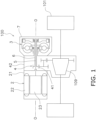
- FIG. 1 is a schematic diagram of the drive unit according to the present preferred embodiment
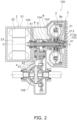
- FIG. 2 is a cross-sectional view of the drive unit according to the present preferred embodiment.
- axial direction refers to an extending direction of a rotational axis O of a prime mover 2 and a torque converter 3.
- circumferential direction refers to a circumferential direction of an imaginary circle about the rotational axis O
- radial direction refers to a radial direction of the imaginary circle about the rotational axis O.
- forward rotation refers to rotation in forward movement of a vehicle
- reverse rotation refers to rotation in backward movement of the vehicle.
- a drive unit 100 includes the prime mover 2, the torque converter 3, a reducer 4 (exemplary power transmission mechanism), an input shaft 5, an output shaft 6, a torque converter casing 7, a hydraulic fluid sump 8 and a first cooling flow pathway 9a.
- the drive unit 100 is installed in, for instance, an electric car.
- the drive unit 100 transmits a torque, outputted from the prime mover 2, to drive wheels 101.
- the torque converter 3, the torque converter casing 7, the hydraulic fluid sump 8 and the first cooling flow pathway 9a will be collectively referred to as a torque converter unit.
- the prime mover 2 includes a prime mover casing 21, a stator 22 and a rotor 23.
- the prime mover 2 is a motor.
- the prime mover 2 is a so-called inner rotor motor.
- the prime mover casing 21 is fixed to a vehicle body frame or so forth and is non-rotatable.
- the stator 22 is fixed to the inner peripheral surface of the prime mover casing 21.
- the stator 22 is non-rotatable.
- the rotor 23 is rotated about the rotational axis O.
- the rotor 23 is disposed radially inside the stator 22.
- the torque converter 3 is disposed at an interval from the prime mover 2 in the axial direction.
- the reducer 4 is disposed between the torque converter 3 and the prime mover 2.
- the rotational axis O of the torque converter 3 is substantially matched with that of the prime mover 2.
- the torque converter 3 is a device to which the torque, outputted from the prime mover 2, is inputted. Additionally, the torque converter 3 amplifies the torque inputted thereto from the prime mover 2, and outputs the amplified torque to the reducer 4.
- the torque converter 3 includes a cover 31, an impeller 32, a turbine 33, a stator 34, a first one-way clutch 35 and a second one-way clutch 36. Besides, the torque converter 3 further includes a centrifugal clutch 37.
- the torque converter 3 is disposed such that the impeller 32 faces the prime mover 2 (the left side in FIG. 3 ) whereas the cover 31 faces opposite to the prime mover 2 (the right side in FIG. 3 ).
- the torque converter 3 is accommodated in the interior of the torque converter casing 7. Hydraulic fluid is supplied to the interior of the torque converter 3.
- the hydraulic fluid is, for instance, hydraulic oil.
- the cover 31 is a component to which the torque, outputted from the prime mover 2, is inputted.
- the cover 31 is rotated by the torque inputted thereto from the prime mover 2.
- the cover 31 is fixed to the input shaft 5 extending from the prime mover 2.
- the cover 31 includes a spline hole to which the input shaft 5 is spline-coupled. Because of this, the cover 31 is unitarily rotated with the input shaft 5.
- the cover 31 is disposed to cover the turbine 33.
- the cover 31 includes a disc portion 311, a cylindrical portion 312 and a cover hub 313.
- the disc portion 311 includes an opening in the middle thereof.
- the cylindrical portion 312 extends from the outer peripheral end of the disc portion 311 toward the prime mover 2.
- the disc portion 311 and the cylindrical portion 312 are provided as a single member.
- the cover hub 313 is fixed to the inner peripheral end of the disc portion 311.
- the cover hub 313 is provided as a member separated from the disc portion 311.
- the cover hub 313 may be provided together with the disc portion 311 as a single member.
- the cover hub 313 includes a first boss portion 313a, a first flange portion 313b and a protruding portion 313c.
- the first boss portion 313a, the first flange portion 313b and the protruding portion 313c are provided as a single member.
- the first boss portion 313a is made in the shape of a cylinder including a spline hole.
- the input shaft 5 is spline-coupled to the first boss portion 313a.
- the first boss portion 313a is rotatably supported by the torque converter casing 7 through a bearing member 102. Because of this, the first boss portion 313a axially extends from the first flange portion 313b to the opposite side of the prime mover 2.
- the first flange portion 313b extends radially outward from the first boss portion 313a. Specifically, the first flange portion 313b extends radially outward from the prime mover 2-side end of the first boss portion 313a.
- the disc portion 311 is fixed to the outer peripheral end of the first flange portion 313b.
- the protruding portion 313c axially extends from the first flange portion 313b.
- the protruding portion 313c extends toward the prime mover 2.
- the protruding portion 313c extends from the outer peripheral end of the first flange portion 313b.
- the protruding portion 313c has a cylindrical shape.
- the protruding portion 313c includes a plurality of through holes 313d. The hydraulic fluid is discharged from the torque converter 3 through the through holes 313d.
- the impeller 32 is rotated unitarily with the cover 31.
- the impeller 32 is fixed to the cover 31.
- the impeller 32 includes an impeller shell 321, a plurality of impeller blades 322, an impeller hub 323 and a plurality of supply flow pathways 324.
- the impeller shell 321 is fixed to the cover 31.
- the plural impeller blades 322 are attached to the inner surface of the impeller shell 321.
- the impeller hub 323 is attached to the inner peripheral end of the impeller shell 321. It should be noted that in the present preferred embodiment, the impeller hub 323 is provided together with the impeller shell 321 as a single member but may be provided as a member separated from the impeller shell 321.
- the impeller hub 323 includes a second boss portion 323a and a second flange portion 323b.
- the second boss portion 323a has a cylindrical shape and axially extends.
- the second boss portion 323a is rotatably supported by the torque converter casing 7 through a bearing member 103 (see FIG. 2 ).
- a stationary shaft 104 axially extends in the interior of the second boss portion 323a.
- the stationary shaft 104 has a cylindrical shape and the output shaft 6 axially extends in the interior of the stationary shaft 104.
- the stationary shaft 104 extends from, for instance, a reducer casing 42 or the torque converter casing 7.
- the stationary shaft 104 is non-rotatable.
- the supply flow pathways 324 are provided in the impeller hub 323. Detailedly, the supply flow pathways 324 are provided in the second flange portion 323b. The supply flow pathways 324 extend radially outward from the inner peripheral surface of the impeller hub 323. Additionally, the supply flow pathways 324 are opened to the interior of a torus T. It should be noted that the torus T is a space enclosed by the impeller 32 and the turbine 33.
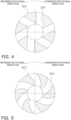
- the supply flow pathways 324 are axially closed. In other words, the supply flow pathways 324 are through holes radially extending in the impeller hub 323. As shown in FIG. 4 , the supply flow pathways 324 extend in a radial shape. The supply flow pathways 324 slant opposite to a forward rotational direction, while extending radially outward. In other words, the supply flow pathways 324 slant in a reverse rotational direction (counterclockwise in FIG. 4 ), while extending radially outward. It should be noted that the extending shape of each supply flow pathway 324 is not limited to a straight shape. For example, as shown in FIG. 5 , each supply flow pathway 324 may extend in a curved shape.
- the turbine 33 is disposed in opposition to the impeller 32. Specifically, the turbine 33 is axially opposed to the impeller 32. The turbine 33 is a component to which a torque is transmitted from the impeller 32 through the hydraulic fluid.
- the turbine 33 includes a turbine shell 331, a plurality of turbine blades 332 and a turbine hub 333.
- the turbine blades 332 are fixed to the inner surface of the turbine shell 331.
- the turbine hub 333 is fixed to the inner peripheral end of the turbine shell 331.
- the turbine hub 333 is fixed to the turbine shell 331 by at least one rivet.
- the turbine hub 333 is provided as a member separated from the turbine shell 331.
- the turbine hub 333 may be provided together with the turbine shell 331 as a single member.
- the output shaft 6 is attached to the turbine hub 333. Detailedly, the output shaft 6 is spline-coupled to the turbine hub 333. The turbine hub 333 is unitarily rotated with the output shaft 6.
- the turbine hub 333 includes a third boss portion 333a and a third flange portion 333b.
- the third boss portion 333a and the third flange portion 333b are provided as a single member.
- the third boss portion 333a has a cylindrical shape and includes a spline hole.
- the output shaft 6 is spline-coupled to the third boss portion 333a.
- the third boss portion 333a axially extends from the third flange portion 333b to the opposite side of the prime mover 2. In other words, the third boss portion 333a axially extends from the third flange portion 333b toward the cover hub 313.
- the third boss portion 333a is disposed at a radial interval from the protruding portion 313c.
- the protruding portion 313c is disposed radially outside the third boss portion 333a.
- the first one-way clutch 35 is disposed between the third boss portion 333a and the protruding portion 313c. It should be noted that without installation of the first one-way clutch 35, the outer peripheral surface of the third boss portion 333a and the inner peripheral surface of the protruding portion 313c are opposed to each other.
- a flow pathway is provided between the cover hub 313 and the distal end of the third boss portion 333a such that the hydraulic fluid flows therethrough.
- the third boss portion 333a is provided with a plurality of cutouts 333c on the distal end thereof. The cutouts 333c radially extend on the distal end of the third boss portion 333a. The hydraulic fluid is discharged from the torque converter 3 through the cutouts 333c and the through holes 313d.
- the third flange portion 333b extends radially outward from the third boss portion 333a. Specifically, the third flange portion 333b extends radially outward from the prime mover 2-side end of the third boss portion 333a.
- the turbine shell 331 is fixed to the outer peripheral end of the third flange portion 333b by the at least one rivet or so forth.
- the stator 34 is configured to regulate the flow of the hydraulic fluid (hydraulic oil) returning from the turbine 33 to the impeller 32.
- the stator 34 is rotatable about the rotational axis O.
- the stator 34 is supported by the stationary shaft 104 through the second one-way clutch 36.
- the stator 34 is disposed axially between the impeller 32 and the turbine 33.
- the stator 34 includes a stator carrier 341 having a disc shape and a plurality of stator blades 342 attached to the outer peripheral surface of the stator carrier 341.
- the first one-way clutch 35 is disposed between the cover 31 and the turbine 33.
- the first one-way clutch 35 makes the cover 31 rotatable relative to the turbine 33 in the forward rotational direction.
- the first one-way clutch 35 is configured such that the cover 31 is rotated relative to the turbine 33. Because of this, in forward movement of the vehicle, the first one-way clutch 35 does not transmit a torque from the cover 31 to the turbine 33.
- the first one-way clutch 35 makes the cover 31 rotate unitarily with the turbine 33 in the reverse rotational direction.
- the first one-way clutch 35 is configured such that the cover 31 is rotated unitarily with the turbine 33. Because of this, in backward movement of the vehicle, the first one-way clutch 35 transmits a torque from the cover 31 to the turbine 33.
- the second one-way clutch 36 is disposed between the stationary shaft 104 and the stator 34.
- the second one-way clutch 36 is configured to make the stator 34 rotatable in the forward rotational direction.
- the second one-way clutch 36 makes the stator 34 non-rotatable in the reverse rotational direction. The torque is transmitted from the impeller 32 to the turbine 33, while being amplified by the stator 34.
- the centrifugal clutch 37 is attached to the turbine 33.
- the centrifugal clutch 37 is unitarily rotated with the turbine 33.
- the centrifugal clutch 37 is configured to couple the cover 31 and the turbine 33 to each other by a centrifugal force generated in rotation of the turbine 33.
- the centrifugal clutch 37 is configured to transmit the torque from the cover 31 to the turbine 33 when the rotational speed of the turbine 33 becomes greater than or equal to a predetermined value.
- the centrifugal clutch 37 includes a plurality of centrifugal elements 371 and a plurality of friction materials 372.
- the friction materials 372 are attached to the outer peripheral surfaces of the centrifugal elements 371, respectively.
- the centrifugal elements 371 are disposed while being radially movable. It should be noted that the centrifugal elements 371 are disposed while being circumferentially immovable. Because of this, the centrifugal elements 371 are rotated together with the turbine 33 and are moved radially outward by centrifugal forces.
- the centrifugal clutch 37 When the rotational speed of the turbine 33 becomes greater than or equal to the predetermined value, the centrifugal clutch 37 is configured such that the centrifugal elements 371 are moved radially outward and the friction materials 372 are engaged by friction with the inner peripheral surface of the cylindrical portion 312 of the cover 31. As a result, the centrifugal clutch 37 is turned to an on state, and the torque outputted from the cover 31 is transmitted to the turbine 33 through the centrifugal clutch 37. It should be noted that even when the centrifugal clutch 37 is turned to the on state, the hydraulic fluid is capable of flowing through the centrifugal clutch 37.
- the centrifugal elements 371 are moved radially inward, whereby the friction materials 372 and the inner peripheral surface of the cylindrical portion 312 of the cover 31, engaged by friction, are disengaged from each other.
- the centrifugal clutch 37 is turned to an off state, and the torque outputted from the cover 31 is not transmitted to the turbine 33 through the centrifugal clutch 37.
- the torque outputted from the cover 31 is transmitted to the impeller 32 and is then transmitted to the turbine 33 through the hydraulic fluid.
- the reducer 4 is disposed axially between the prime mover 2 and the torque converter 3.
- the reducer 4 transmits a torque, outputted from the torque converter 3, to the drive wheel 101 side.
- the reducer 4 amplifies the torque outputted from the torque converter 3 and transmits the amplified torque to the drive wheel 101 side through a differential gear 109.
- the reducer 4 includes a plurality of gears 41 and the reducer casing 42 accommodating the respective gears 41.
- one of the plural gears 41 is fixed to the output shaft 6.
- one of the gears 41 is provided together with the output shaft 6 as a single member.
- the input shaft 5 extends from the prime mover 2.
- the input shaft 5 extends toward the torque converter 3.
- the rotational axis of the input shaft 5 is substantially matched with that of the prime mover 2 and that of the torque converter 3.
- the input shaft 5 inputs the torque, outputted from the prime mover 2, to the torque converter 3.
- the input shaft 5 is attached at the distal end thereof to the cover hub 313 of the torque converter 3.
- the input shaft 5 is unitarily rotated with the rotor 23 of the prime mover 2.
- the input shaft 5 extends through the interior of the output shaft 6.
- the input shaft 5 is solid.
- the input shaft 5 includes a communicating pathway 51 in the distal end thereof.
- the communicating pathway 51 extends in the axial direction. Besides, the communicating pathway 51 is opened toward the first cooling flow pathway 9a.
- the output shaft 6 outputs the torque outputted from the torque converter 3.
- the output shaft 6 outputs the torque, outputted from the torque converter 3, to the reducer 4.
- the output shaft 6 extends from the torque converter 3 toward the prime mover 2.
- the output shaft 6 has a cylindrical shape.
- the input shaft 5 extends through the interior of the output shaft 6.
- the output shaft 6 is attached at one end (the right end in FIG. 2 ) to the turbine 33 of the torque converter 3.
- the output shaft 6 is rotatably supported at the other end (the left end in FIG. 2 ) by the reducer casing 42 through a bearing member 105.
- the torque converter casing 7 accommodates the torque converter 3.
- the torque converter casing 7 is provided together with the reducer casing 42 as a single member.
- the torque converter casing 7 may be provided as a member separated from the reducer casing 42.
- the torque converter casing 7 includes a side wall portion 71, an outer wall portion 72 and a plurality of heat dissipation fins 73.
- the sidewall portion 71 is disposed in opposition to the cover 31 of the torque converter 3.
- the sidewall portion 71 is disposed orthogonal to the rotational axis O.
- the torque converter 3 is disposed on one axial side (the left side in FIG. 6 ) of the sidewall portion 71.
- the sidewall portion 71 makes contact at the other side (the right lateral surface in FIG. 6 ) with external air.
- a member, functioning as a heat source is not disposed on the other side of the sidewall portion 71.
- the cover 31 is rotatably attached to the middle part of the sidewall portion 71 through the bearing member 102.
- the sidewall portion 71 is made of a material, having a high specific heat and a high thermal conductivity, so as to quickly absorb a large amount of heat from the hydraulic fluid flowing through the first cooling flow pathway 9a and release the absorbed heat to the atmosphere.
- the sidewall portion 71 is made of magnesium, aluminum or so forth.
- the outer wall portion 72 is disposed in opposition to the outer peripheral surface of the torque converter 3.
- the outer wall portion 72 is provided together with the sidewall portion 71 as a single member. However, the outer wall portion 72 may be provided as a member separated from the sidewall portion 71.
- the outer wall portion 72 extends toward the prime mover 2 from the outer peripheral end of the sidewall portion 71.
- the outer wall portion 72 extends substantially in parallel to the rotational axis O. It should be noted that the distal end (the prime mover 2-side end) of the outer wall portion 72 slants radially inward.
- the outer wall portion 72 can be made of a similar material to the sidewall portion 71.
- the heat dissipation fins 73 are provided on the sidewall portion 71.
- the heat dissipation fins 73 extend from the sidewall portion 71 to the opposite side (rightward in FIG. 6 ) of the torque converter 3.
- the heat dissipation fins 73 are attached to the sidewall portion 71 in order to efficiently dissipate the heat of the hydraulic fluid flowing through the first cooling flow pathway 9a.
- the thermal conductivity of the heat dissipation fins 73 is preferably set to be equivalent to or higher than that of the sidewall portion 71 but is not particularly limited to this setting.
- the heat dissipation fins 73 are made of, for instance, magnesium, aluminum, copper or so forth.
- the first cooling flow pathway 9a is a flow pathway for cooling the hydraulic fluid discharged from the torque converter 3.
- the first cooling flow pathway 9a extends in the interior of the torque converter casing 7.
- the first cooling flow pathway 9a is provided only in the upper half of the torque converter casing 7 (see FIG. 2 ).
- the first cooling flow pathway 9a extends from the middle part to the outer peripheral part in the interior of the sidewall portion 71 and axially extends therefrom beyond the torque converter 3 in the interior of the outer wall portion 72.
- the first cooling flow pathway 9a is communicated with the hydraulic fluid sump 8.
- the first cooling flow pathway 9a includes a plurality of paths in the interior of the sidewall portion 71.
- the first cooling flow pathway 9a is divided into two paths in the interior of the sidewall portion 71.
- the first cooling flow pathway 9a extends from the middle part to the outer peripheral part not in a straight shape but in a winding shape.
- the first cooling flow pathway 9a may include a plurality of paths in the interior of the outer wall portion 72 as well. In the present preferred embodiment, the first cooling flow pathway 9a is divided into, for instance, three paths in the interior of the outer wall portion 72. The first cooling flow pathway 9a axially extends in a straight shape in the interior of the outer wall portion 72. Alternatively, the first cooling flow pathway 9a may extend in a winding shape in the interior of the outer wall portion 72.
- the hydraulic fluid sump 8 is disposed to axially interpose the torque converter 3 together with the sidewall portion 71 therebetween.
- the hydraulic fluid sump 8 the torque converter 3 and the sidewall portion 71 are axially aligned in this order.
- the hydraulic fluid sump 8 is disposed in the interior of the reducer casing 42.
- the hydraulic fluid sump 8 is disposed above the rotational axis O.
- the hydraulic fluid sump 8 contains the hydraulic fluid to be supplied to the torque converter 3 in the interior thereof.
- the hydraulic fluid sump 8 is provided with a supply port 81 in the bottom surface thereof.
- the hydraulic fluid, discharged from the supply port 81, is supplied to the torque converter 3 through a flow pathway 106 provided between the stationary shaft 104 and the second boss portion 323a of the impeller hub 323.
- the torque converter unit may further include a second cooling flow pathway 9b.
- the second cooling flow pathway 9b extends through the interior of a compartment 107 of a vehicle into which the torque converter unit is installed.
- the hydraulic fluid, discharged from the torque converter 3 flows through the second cooling flow pathway 9b.
- the hydraulic fluid, flowing through the second cooling flow pathway 9b, is cooled while dissipating heat thereof into the compartment 107.
- the hydraulic fluid is supplied to the second cooling flow pathway 9b from the communicating pathway 51. Additionally, the hydraulic fluid is returned to the hydraulic fluid sump 8 through the second cooling flow pathway 9b.
- the torque converter unit further includes a selector mechanism 11.
- the selector mechanism 11 is configured to select either the first cooling flow pathway 9a or the second cooling flow pathway 9b as a cooling flow pathway for supplying the hydraulic fluid discharged from the torque converter 3.
- the torque converter 3 may further include a plurality of elastic members 38.
- the elastic members 38 are disposed circumferentially between the first one-way clutch 35 and the cover 31.
- the elastic members 38 transmit a torque, applied in the reverse rotational direction from the cover 31, to the first one-way clutch 35. It should be noted that, when the cover 31 is rotated with respect to the first one-way clutch 35 by more than a predetermined angle in the reverse rotational direction, first stopper surfaces 314 of the cover 31 make contact with second stopper surfaces 351 of the first one-way clutch 35. As a result, the torque, applied from the cover 31, is directly transmitted to the first one-way clutch 35.
- the elastic members 38 may be disposed circumferentially between the first one-way clutch 35 and the turbine 33. In this case, the elastic members 38 transmit a torque, applied from the first one-way clutch 35 in the reverse rotational direction, to the turbine 33.
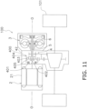
- the present power transmission mechanism may include a planetary gear mechanism 400 and a clutch 401.
- the planetary gear mechanism 400 includes a sun gear 402, a plurality of planet gears 403, a planet carrier 404 and a ring gear 405.
- the sun gear 402 is attached to the input shaft 5.
- the sun gear 402 is unitarily rotated with the input shaft 5.
- the planet carrier 404 is attached to the output shaft 6.
- the planet carrier 404 is unitarily rotated with the output shaft 6.
- the clutch 401 is disposed between a non-rotatable member (e.g., the reducer casing 42 or the prime mover casing 21) and the ring gear 405. Besides, the clutch 401 is configured to brake rotation of the ring gear 405.
- a non-rotatable member e.g., the reducer casing 42 or the prime mover casing 21
- the clutch 401 is configured to brake rotation of the ring gear 405.
- the clutch 401 is, for instance, a one-way clutch.
- the clutch 401 makes the ring gear 405 rotatable in forward rotation of the input shaft 5 and the output shaft 6.
- the clutch 401 makes the ring gear 405 non-rotatable in reverse rotation of the input shaft 5 and the output shaft 6.
Landscapes
- Engineering & Computer Science (AREA)
- General Engineering & Computer Science (AREA)
- Mechanical Engineering (AREA)
- Chemical & Material Sciences (AREA)
- Combustion & Propulsion (AREA)
- Transportation (AREA)
- Arrangement Of Transmissions (AREA)
- Hybrid Electric Vehicles (AREA)
- Retarders (AREA)
Description
- The present invention relates to a drive unit for a vehicle.
-
JP H04 208643 A JP H03 262726 A Japan Laid-open Patent Application Publication No. 2013-60996 US 2019/092157 A1 disclose electric cars having an electric motor as prime mover. In well-known electric cars, a torque, outputted from a motor, is transmitted to drive wheels through a reducer and a differential gear. For example, in an electric car disclosed inJapan Laid-open Patent Application Publication No. 2013-60996 US 2019/092157 A1 (which forms the basis for the preamble of claim 1) discloses an electric car with an electric motor, a torque converter and a power transmission mechanism.JP 2001 287556 A - It has been demanded to enhance a driving force in such an electric cars as described above. In view of this, it is an object of the present invention to provide a drive unit capable of enhancing a driving force.
- Such object is achieved by a drive unit according to claim 1. Advantageous embodiments are the subject-matter of the dependent claims. A drive unit according to an aspect of the present invention includes a prime mover, a torque converter and a power transmission mechanism. The prime mover is an electric motor. The torque converter is a component to which a torque is inputted from the prime mover. The power transmission mechanism is disposed between the prime mover and the torque converter. Besides, the power transmission mechanism transmits the torque outputted from the torque converter therethrough toward a drive wheel.
- According to this configuration, a torque is outputted from the prime mover toward the drive wheel through the torque converter. Hence, a driving force can be enhanced. Besides, the torque converter amplifies the torque inputted thereto from the prime mover and outputs the amplified torque to the power transmission mechanism. Hence, the torque converter is normally disposed between the prime mover and the power transmission mechanism. By contrast, in the present invention, the power transmission mechanism is disposed between the prime mover and the torque converter. In other words, attaching the torque converter is enabled without greatly changing the layout of the prime mover and the power transmission mechanism in well-known electric cars. It should be noted that in general, the prime mover is disposed on one side of the power transmission mechanism, whereas an unused space exists on the other side of the power transmission mechanism. Because of this, the unused space can be effectively utilized for disposing the torque converter in the present invention.
- Preferably, the power transmission mechanism is a reducer.
- Preferably, the drive unit further includes an output shaft and an input shaft. The output shaft outputs the torque outputted from the torque converter. The input shaft extends from the prime mover and inputs the torque from the prime mover therethrough to the torque converter.
- Preferably, the output shaft extends from the torque converter toward the prime mover.
- Preferably, the output shaft has a cylindrical shape. Besides, the input shaft extends in an interior of the output shaft.
- Preferably, the torque converter includes a cover, an impeller and a turbine. The cover is a component to which the input shaft is fixed. The impeller is unitarily rotated with the cover. The turbine is opposed to the impeller.
- Preferably, the impeller is disposed closer to the prime mover than the cover.
- Preferably, the power transmission mechanism includes a planetary gear mechanism and a clutch. The planetary gear mechanism includes a sun gear, a planet gear, a planet carrier and a ring gear. The clutch is configured to brake rotation of the ring gear. The sun gear is unitarily rotated with the input shaft. The planet carrier is unitarily rotated with the output shaft.
- Preferably, the clutch is a one-way clutch. The clutch is configured to make the ring gear rotatable in forward rotation of the input shaft and the output shaft. Besides, the clutch is configured to make the ring gear non-rotatable in reverse rotation of the input shaft and the output shaft.
- Overall, according to the present invention, a driving force can be enhanced.
-
-
FIG. 1 is a schematic diagram of a drive unit. -
FIG. 2 is a cross-sectional view of the drive unit. -
FIG. 3 is a cross-sectional view of a torque converter. -
FIG. 4 is a cross-sectional view of a type of impeller hub. -
FIG. 5 is a cross-sectional view of another type of impeller hub. -
FIG. 6 is a cross-sectional view of the drive unit shown for indicating a first cooling flow pathway. -
FIG. 7 is a cross-sectional view of a sidewall portion of a type of cover. -
FIG. 8 is a cross-sectional view of a sidewall portion of another type of cover. -
FIG. 9 is a schematic diagram of a drive unit according to a modification. -
FIG. 10 is a schematic diagram of a first one-way clutch according to another modification. -
FIG. 11 is a schematic diagram of a drive unit according to yet another modification. - A preferred embodiment of a drive unit according to the present invention will be hereinafter explained with reference to drawings.
FIG. 1 is a schematic diagram of the drive unit according to the present preferred embodiment, whereasFIG. 2 is a cross-sectional view of the drive unit according to the present preferred embodiment. It should be noted that in the following explanation, the term "axial direction" refers to an extending direction of a rotational axis O of aprime mover 2 and atorque converter 3. On the other hand, the term "circumferential direction" refers to a circumferential direction of an imaginary circle about the rotational axis O, whereas the term "radial direction" refers to a radial direction of the imaginary circle about the rotational axis O. Moreover, the term "forward rotation" refers to rotation in forward movement of a vehicle, whereas the term "reverse rotation" refers to rotation in backward movement of the vehicle. - As shown in
FIGS. 1 and2 , adrive unit 100 includes theprime mover 2, thetorque converter 3, a reducer 4 (exemplary power transmission mechanism), aninput shaft 5, anoutput shaft 6, atorque converter casing 7, a hydraulicfluid sump 8 and a firstcooling flow pathway 9a. Thedrive unit 100 is installed in, for instance, an electric car. Thedrive unit 100 transmits a torque, outputted from theprime mover 2, to drivewheels 101. It should be noted that thetorque converter 3, thetorque converter casing 7, the hydraulicfluid sump 8 and the firstcooling flow pathway 9a will be collectively referred to as a torque converter unit. - The
prime mover 2 includes a prime mover casing 21, astator 22 and arotor 23. In the present preferred embodiment, theprime mover 2 is a motor. Detailedly, theprime mover 2 is a so-called inner rotor motor. The prime mover casing 21 is fixed to a vehicle body frame or so forth and is non-rotatable. - The
stator 22 is fixed to the inner peripheral surface of theprime mover casing 21. Thestator 22 is non-rotatable. Therotor 23 is rotated about the rotational axis O. Therotor 23 is disposed radially inside thestator 22. - The
torque converter 3 is disposed at an interval from theprime mover 2 in the axial direction. Thereducer 4 is disposed between thetorque converter 3 and theprime mover 2. The rotational axis O of thetorque converter 3 is substantially matched with that of theprime mover 2. Thetorque converter 3 is a device to which the torque, outputted from theprime mover 2, is inputted. Additionally, thetorque converter 3 amplifies the torque inputted thereto from theprime mover 2, and outputs the amplified torque to thereducer 4. - As shown in
FIG. 3 , thetorque converter 3 includes acover 31, animpeller 32, aturbine 33, astator 34, a first one-way clutch 35 and a second one-way clutch 36. Besides, thetorque converter 3 further includes acentrifugal clutch 37. - The
torque converter 3 is disposed such that theimpeller 32 faces the prime mover 2 (the left side inFIG. 3 ) whereas thecover 31 faces opposite to the prime mover 2 (the right side inFIG. 3 ). Thetorque converter 3 is accommodated in the interior of thetorque converter casing 7. Hydraulic fluid is supplied to the interior of thetorque converter 3. The hydraulic fluid is, for instance, hydraulic oil. - The
cover 31 is a component to which the torque, outputted from theprime mover 2, is inputted. Thecover 31 is rotated by the torque inputted thereto from theprime mover 2. Thecover 31 is fixed to theinput shaft 5 extending from theprime mover 2. For example, thecover 31 includes a spline hole to which theinput shaft 5 is spline-coupled. Because of this, thecover 31 is unitarily rotated with theinput shaft 5. Thecover 31 is disposed to cover theturbine 33. - The
cover 31 includes adisc portion 311, acylindrical portion 312 and acover hub 313. Thedisc portion 311 includes an opening in the middle thereof. Thecylindrical portion 312 extends from the outer peripheral end of thedisc portion 311 toward theprime mover 2. Thedisc portion 311 and thecylindrical portion 312 are provided as a single member. - The
cover hub 313 is fixed to the inner peripheral end of thedisc portion 311. In the present preferred embodiment, thecover hub 313 is provided as a member separated from thedisc portion 311. However, thecover hub 313 may be provided together with thedisc portion 311 as a single member. - The
cover hub 313 includes afirst boss portion 313a, afirst flange portion 313b and a protrudingportion 313c. Thefirst boss portion 313a, thefirst flange portion 313b and the protrudingportion 313c are provided as a single member. - The
first boss portion 313a is made in the shape of a cylinder including a spline hole. Theinput shaft 5 is spline-coupled to thefirst boss portion 313a. As shown inFIG. 2 , thefirst boss portion 313a is rotatably supported by thetorque converter casing 7 through a bearingmember 102. Because of this, thefirst boss portion 313a axially extends from thefirst flange portion 313b to the opposite side of theprime mover 2. - As shown in
FIG. 3 , thefirst flange portion 313b extends radially outward from thefirst boss portion 313a. Detailedly, thefirst flange portion 313b extends radially outward from the prime mover 2-side end of thefirst boss portion 313a. Thedisc portion 311 is fixed to the outer peripheral end of thefirst flange portion 313b. - The protruding
portion 313c axially extends from thefirst flange portion 313b. The protrudingportion 313c extends toward theprime mover 2. The protrudingportion 313c extends from the outer peripheral end of thefirst flange portion 313b. The protrudingportion 313c has a cylindrical shape. The protrudingportion 313c includes a plurality of throughholes 313d. The hydraulic fluid is discharged from thetorque converter 3 through the throughholes 313d. - The
impeller 32 is rotated unitarily with thecover 31. Theimpeller 32 is fixed to thecover 31. Theimpeller 32 includes animpeller shell 321, a plurality ofimpeller blades 322, animpeller hub 323 and a plurality ofsupply flow pathways 324. - The
impeller shell 321 is fixed to thecover 31. Theplural impeller blades 322 are attached to the inner surface of theimpeller shell 321. - The
impeller hub 323 is attached to the inner peripheral end of theimpeller shell 321. It should be noted that in the present preferred embodiment, theimpeller hub 323 is provided together with theimpeller shell 321 as a single member but may be provided as a member separated from theimpeller shell 321. - The
impeller hub 323 includes asecond boss portion 323a and asecond flange portion 323b. Thesecond boss portion 323a has a cylindrical shape and axially extends. Thesecond boss portion 323a is rotatably supported by thetorque converter casing 7 through a bearing member 103 (seeFIG. 2 ). Astationary shaft 104 axially extends in the interior of thesecond boss portion 323a. It should be noted that thestationary shaft 104 has a cylindrical shape and theoutput shaft 6 axially extends in the interior of thestationary shaft 104. Besides, thestationary shaft 104 extends from, for instance, areducer casing 42 or thetorque converter casing 7. Thestationary shaft 104 is non-rotatable. - The
supply flow pathways 324 are provided in theimpeller hub 323. Detailedly, thesupply flow pathways 324 are provided in thesecond flange portion 323b. Thesupply flow pathways 324 extend radially outward from the inner peripheral surface of theimpeller hub 323. Additionally, thesupply flow pathways 324 are opened to the interior of a torus T. It should be noted that the torus T is a space enclosed by theimpeller 32 and theturbine 33. - The
supply flow pathways 324 are axially closed. In other words, thesupply flow pathways 324 are through holes radially extending in theimpeller hub 323. As shown inFIG. 4 , thesupply flow pathways 324 extend in a radial shape. Thesupply flow pathways 324 slant opposite to a forward rotational direction, while extending radially outward. In other words, thesupply flow pathways 324 slant in a reverse rotational direction (counterclockwise inFIG. 4 ), while extending radially outward. It should be noted that the extending shape of eachsupply flow pathway 324 is not limited to a straight shape. For example, as shown inFIG. 5 , eachsupply flow pathway 324 may extend in a curved shape. - As shown in
FIG. 3 , theturbine 33 is disposed in opposition to theimpeller 32. Detailedly, theturbine 33 is axially opposed to theimpeller 32. Theturbine 33 is a component to which a torque is transmitted from theimpeller 32 through the hydraulic fluid. - The
turbine 33 includes aturbine shell 331, a plurality ofturbine blades 332 and aturbine hub 333. Theturbine blades 332 are fixed to the inner surface of theturbine shell 331. - The
turbine hub 333 is fixed to the inner peripheral end of theturbine shell 331. For example, theturbine hub 333 is fixed to theturbine shell 331 by at least one rivet. In the present preferred embodiment, theturbine hub 333 is provided as a member separated from theturbine shell 331. However, theturbine hub 333 may be provided together with theturbine shell 331 as a single member. - The
output shaft 6 is attached to theturbine hub 333. Detailedly, theoutput shaft 6 is spline-coupled to theturbine hub 333. Theturbine hub 333 is unitarily rotated with theoutput shaft 6. - The
turbine hub 333 includes athird boss portion 333a and athird flange portion 333b. Thethird boss portion 333a and thethird flange portion 333b are provided as a single member. - The
third boss portion 333a has a cylindrical shape and includes a spline hole. Theoutput shaft 6 is spline-coupled to thethird boss portion 333a. Thethird boss portion 333a axially extends from thethird flange portion 333b to the opposite side of theprime mover 2. In other words, thethird boss portion 333a axially extends from thethird flange portion 333b toward thecover hub 313. - The
third boss portion 333a is disposed at a radial interval from the protrudingportion 313c. In other words, the protrudingportion 313c is disposed radially outside thethird boss portion 333a. The first one-way clutch 35 is disposed between thethird boss portion 333a and the protrudingportion 313c. It should be noted that without installation of the first one-way clutch 35, the outer peripheral surface of thethird boss portion 333a and the inner peripheral surface of the protrudingportion 313c are opposed to each other. - A flow pathway is provided between the
cover hub 313 and the distal end of thethird boss portion 333a such that the hydraulic fluid flows therethrough. In the present preferred embodiment, thethird boss portion 333a is provided with a plurality of cutouts 333c on the distal end thereof. The cutouts 333c radially extend on the distal end of thethird boss portion 333a. The hydraulic fluid is discharged from thetorque converter 3 through the cutouts 333c and the throughholes 313d. - The
third flange portion 333b extends radially outward from thethird boss portion 333a. Detailedly, thethird flange portion 333b extends radially outward from the prime mover 2-side end of thethird boss portion 333a. Theturbine shell 331 is fixed to the outer peripheral end of thethird flange portion 333b by the at least one rivet or so forth. - The
stator 34 is configured to regulate the flow of the hydraulic fluid (hydraulic oil) returning from theturbine 33 to theimpeller 32. Thestator 34 is rotatable about the rotational axis O. For example, thestator 34 is supported by thestationary shaft 104 through the second one-way clutch 36. Thestator 34 is disposed axially between theimpeller 32 and theturbine 33. - The
stator 34 includes astator carrier 341 having a disc shape and a plurality ofstator blades 342 attached to the outer peripheral surface of thestator carrier 341. - The first one-way clutch 35 is disposed between the
cover 31 and theturbine 33. The first one-way clutch 35 makes thecover 31 rotatable relative to theturbine 33 in the forward rotational direction. In other words, when theprime mover 2 is forwardly rotated to move the vehicle forward, the first one-way clutch 35 is configured such that thecover 31 is rotated relative to theturbine 33. Because of this, in forward movement of the vehicle, the first one-way clutch 35 does not transmit a torque from thecover 31 to theturbine 33. - By contrast, the first one-way clutch 35 makes the
cover 31 rotate unitarily with theturbine 33 in the reverse rotational direction. In other words, when theprime mover 2 is reversely rotated to move the vehicle backward, the first one-way clutch 35 is configured such that thecover 31 is rotated unitarily with theturbine 33. Because of this, in backward movement of the vehicle, the first one-way clutch 35 transmits a torque from thecover 31 to theturbine 33. - The second one-way clutch 36 is disposed between the
stationary shaft 104 and thestator 34. The second one-way clutch 36 is configured to make thestator 34 rotatable in the forward rotational direction. By contrast, the second one-way clutch 36 makes thestator 34 non-rotatable in the reverse rotational direction. The torque is transmitted from theimpeller 32 to theturbine 33, while being amplified by thestator 34. - The centrifugal clutch 37 is attached to the
turbine 33. The centrifugal clutch 37 is unitarily rotated with theturbine 33. The centrifugal clutch 37 is configured to couple thecover 31 and theturbine 33 to each other by a centrifugal force generated in rotation of theturbine 33. Detailedly, the centrifugal clutch 37 is configured to transmit the torque from thecover 31 to theturbine 33 when the rotational speed of theturbine 33 becomes greater than or equal to a predetermined value. - The centrifugal clutch 37 includes a plurality of
centrifugal elements 371 and a plurality offriction materials 372. Thefriction materials 372 are attached to the outer peripheral surfaces of thecentrifugal elements 371, respectively. Thecentrifugal elements 371 are disposed while being radially movable. It should be noted that thecentrifugal elements 371 are disposed while being circumferentially immovable. Because of this, thecentrifugal elements 371 are rotated together with theturbine 33 and are moved radially outward by centrifugal forces. - When the rotational speed of the
turbine 33 becomes greater than or equal to the predetermined value, the centrifugal clutch 37 is configured such that thecentrifugal elements 371 are moved radially outward and thefriction materials 372 are engaged by friction with the inner peripheral surface of thecylindrical portion 312 of thecover 31. As a result, the centrifugal clutch 37 is turned to an on state, and the torque outputted from thecover 31 is transmitted to theturbine 33 through thecentrifugal clutch 37. It should be noted that even when the centrifugal clutch 37 is turned to the on state, the hydraulic fluid is capable of flowing through thecentrifugal clutch 37. - When the rotational speed of the
turbine 33 becomes less than the predetermined value, thecentrifugal elements 371 are moved radially inward, whereby thefriction materials 372 and the inner peripheral surface of thecylindrical portion 312 of thecover 31, engaged by friction, are disengaged from each other. As a result, the centrifugal clutch 37 is turned to an off state, and the torque outputted from thecover 31 is not transmitted to theturbine 33 through thecentrifugal clutch 37. In other words, the torque outputted from thecover 31 is transmitted to theimpeller 32 and is then transmitted to theturbine 33 through the hydraulic fluid. - As shown in
FIG. 2 , thereducer 4 is disposed axially between theprime mover 2 and thetorque converter 3. Thereducer 4 transmits a torque, outputted from thetorque converter 3, to thedrive wheel 101 side. Detailedly, thereducer 4 amplifies the torque outputted from thetorque converter 3 and transmits the amplified torque to thedrive wheel 101 side through adifferential gear 109. It should be noted that thereducer 4 includes a plurality ofgears 41 and thereducer casing 42 accommodating the respective gears 41. It should be also noted that one of the plural gears 41 is fixed to theoutput shaft 6. In the present preferred embodiment, one of thegears 41 is provided together with theoutput shaft 6 as a single member. - The
input shaft 5 extends from theprime mover 2. Theinput shaft 5 extends toward thetorque converter 3. The rotational axis of theinput shaft 5 is substantially matched with that of theprime mover 2 and that of thetorque converter 3. - The
input shaft 5 inputs the torque, outputted from theprime mover 2, to thetorque converter 3. Theinput shaft 5 is attached at the distal end thereof to thecover hub 313 of thetorque converter 3. Theinput shaft 5 is unitarily rotated with therotor 23 of theprime mover 2. Theinput shaft 5 extends through the interior of theoutput shaft 6. Theinput shaft 5 is solid. Theinput shaft 5 includes a communicatingpathway 51 in the distal end thereof. The communicatingpathway 51 extends in the axial direction. Besides, the communicatingpathway 51 is opened toward the firstcooling flow pathway 9a. - The
output shaft 6 outputs the torque outputted from thetorque converter 3. Theoutput shaft 6 outputs the torque, outputted from thetorque converter 3, to thereducer 4. Theoutput shaft 6 extends from thetorque converter 3 toward theprime mover 2. - The
output shaft 6 has a cylindrical shape. Theinput shaft 5 extends through the interior of theoutput shaft 6. Theoutput shaft 6 is attached at one end (the right end inFIG. 2 ) to theturbine 33 of thetorque converter 3. On the other hand, theoutput shaft 6 is rotatably supported at the other end (the left end inFIG. 2 ) by thereducer casing 42 through a bearingmember 105. - As shown in
FIG. 6 , thetorque converter casing 7 accommodates thetorque converter 3. In the present preferred embodiment, thetorque converter casing 7 is provided together with thereducer casing 42 as a single member. However, thetorque converter casing 7 may be provided as a member separated from thereducer casing 42. - The
torque converter casing 7 includes aside wall portion 71, anouter wall portion 72 and a plurality ofheat dissipation fins 73. Thesidewall portion 71 is disposed in opposition to thecover 31 of thetorque converter 3. Thesidewall portion 71 is disposed orthogonal to the rotational axis O. - The
torque converter 3 is disposed on one axial side (the left side inFIG. 6 ) of thesidewall portion 71. On the other hand, thesidewall portion 71 makes contact at the other side (the right lateral surface inFIG. 6 ) with external air. In other words, a member, functioning as a heat source, is not disposed on the other side of thesidewall portion 71. - The
cover 31 is rotatably attached to the middle part of thesidewall portion 71 through the bearingmember 102. Thesidewall portion 71 is made of a material, having a high specific heat and a high thermal conductivity, so as to quickly absorb a large amount of heat from the hydraulic fluid flowing through the firstcooling flow pathway 9a and release the absorbed heat to the atmosphere. For example, thesidewall portion 71 is made of magnesium, aluminum or so forth. - The
outer wall portion 72 is disposed in opposition to the outer peripheral surface of thetorque converter 3. Theouter wall portion 72 is provided together with thesidewall portion 71 as a single member. However, theouter wall portion 72 may be provided as a member separated from thesidewall portion 71. Theouter wall portion 72 extends toward theprime mover 2 from the outer peripheral end of thesidewall portion 71. Theouter wall portion 72 extends substantially in parallel to the rotational axis O. It should be noted that the distal end (the prime mover 2-side end) of theouter wall portion 72 slants radially inward. Theouter wall portion 72 can be made of a similar material to thesidewall portion 71. - The
heat dissipation fins 73 are provided on thesidewall portion 71. Theheat dissipation fins 73 extend from thesidewall portion 71 to the opposite side (rightward inFIG. 6 ) of thetorque converter 3. Theheat dissipation fins 73 are attached to thesidewall portion 71 in order to efficiently dissipate the heat of the hydraulic fluid flowing through the firstcooling flow pathway 9a. The thermal conductivity of theheat dissipation fins 73 is preferably set to be equivalent to or higher than that of thesidewall portion 71 but is not particularly limited to this setting. Theheat dissipation fins 73 are made of, for instance, magnesium, aluminum, copper or so forth. - The first
cooling flow pathway 9a is a flow pathway for cooling the hydraulic fluid discharged from thetorque converter 3. The firstcooling flow pathway 9a extends in the interior of thetorque converter casing 7. In the present preferred embodiment, the firstcooling flow pathway 9a is provided only in the upper half of the torque converter casing 7 (seeFIG. 2 ). - The first
cooling flow pathway 9a extends from the middle part to the outer peripheral part in the interior of thesidewall portion 71 and axially extends therefrom beyond thetorque converter 3 in the interior of theouter wall portion 72. The firstcooling flow pathway 9a is communicated with the hydraulicfluid sump 8. - As shown in
FIG. 7 orFIG. 8 , the firstcooling flow pathway 9a includes a plurality of paths in the interior of thesidewall portion 71. In the present preferred embodiment, the firstcooling flow pathway 9a is divided into two paths in the interior of thesidewall portion 71. In the interior of thesidewall portion 71, the firstcooling flow pathway 9a extends from the middle part to the outer peripheral part not in a straight shape but in a winding shape. - The first
cooling flow pathway 9a may include a plurality of paths in the interior of theouter wall portion 72 as well. In the present preferred embodiment, the firstcooling flow pathway 9a is divided into, for instance, three paths in the interior of theouter wall portion 72. The firstcooling flow pathway 9a axially extends in a straight shape in the interior of theouter wall portion 72. Alternatively, the firstcooling flow pathway 9a may extend in a winding shape in the interior of theouter wall portion 72. - As shown in
FIG. 6 , the hydraulicfluid sump 8 is disposed to axially interpose thetorque converter 3 together with thesidewall portion 71 therebetween. In other words, the hydraulicfluid sump 8, thetorque converter 3 and thesidewall portion 71 are axially aligned in this order. The hydraulicfluid sump 8 is disposed in the interior of thereducer casing 42. The hydraulicfluid sump 8 is disposed above the rotational axis O. - The hydraulic
fluid sump 8 contains the hydraulic fluid to be supplied to thetorque converter 3 in the interior thereof. The hydraulicfluid sump 8 is provided with asupply port 81 in the bottom surface thereof. The hydraulic fluid, discharged from thesupply port 81, is supplied to thetorque converter 3 through aflow pathway 106 provided between thestationary shaft 104 and thesecond boss portion 323a of theimpeller hub 323. - Specifically, a centrifugal force is generated in rotation of the
impeller 32 of thetorque converter 3, whereby the hydraulic fluid residing in the interior of theflow pathway 106 is supplied to the interior of the torus T through thesupply flow pathways 324. Then, the hydraulic fluid, discharged from thetorque converter 3, flows to the firstcooling flow pathway 9a through the communicatingpathway 51. Subsequently, the hydraulic fluid, cooled while flowing through the firstcooling flow pathway 9a, is returned to the hydraulicfluid sump 8. - One preferred embodiment of the present invention has been explained above. However, the present invention is not limited to the above, and a variety of changes can be made without departing from the scope of the claims.
- For example, as shown in
FIG. 9 , the torque converter unit may further include a secondcooling flow pathway 9b. The secondcooling flow pathway 9b extends through the interior of acompartment 107 of a vehicle into which the torque converter unit is installed. The hydraulic fluid, discharged from thetorque converter 3, flows through the secondcooling flow pathway 9b. The hydraulic fluid, flowing through the secondcooling flow pathway 9b, is cooled while dissipating heat thereof into thecompartment 107. - The hydraulic fluid is supplied to the second
cooling flow pathway 9b from the communicatingpathway 51. Additionally, the hydraulic fluid is returned to the hydraulicfluid sump 8 through the secondcooling flow pathway 9b. - The torque converter unit further includes a
selector mechanism 11. Theselector mechanism 11 is configured to select either the firstcooling flow pathway 9a or the secondcooling flow pathway 9b as a cooling flow pathway for supplying the hydraulic fluid discharged from thetorque converter 3. - As shown in
FIG. 10 , thetorque converter 3 may further include a plurality ofelastic members 38. Theelastic members 38 are disposed circumferentially between the first one-way clutch 35 and thecover 31. Theelastic members 38 transmit a torque, applied in the reverse rotational direction from thecover 31, to the first one-way clutch 35. It should be noted that, when thecover 31 is rotated with respect to the first one-way clutch 35 by more than a predetermined angle in the reverse rotational direction, first stopper surfaces 314 of thecover 31 make contact with second stopper surfaces 351 of the first one-way clutch 35. As a result, the torque, applied from thecover 31, is directly transmitted to the first one-way clutch 35. - In reverse rotation as described above, the torque, applied from the
cover 31, is firstly transmitted to the first one-way clutch 35 through theelastic members 38, whereby massive and sudden torque transmission can be eased. - It should be noted that the
elastic members 38 may be disposed circumferentially between the first one-way clutch 35 and theturbine 33. In this case, theelastic members 38 transmit a torque, applied from the first one-way clutch 35 in the reverse rotational direction, to theturbine 33. - As shown in
FIG. 11 , the present power transmission mechanism may include aplanetary gear mechanism 400 and a clutch 401. Theplanetary gear mechanism 400 includes asun gear 402, a plurality of planet gears 403, aplanet carrier 404 and aring gear 405. - The
sun gear 402 is attached to theinput shaft 5. Thesun gear 402 is unitarily rotated with theinput shaft 5. Theplanet carrier 404 is attached to theoutput shaft 6. Theplanet carrier 404 is unitarily rotated with theoutput shaft 6. - The clutch 401 is disposed between a non-rotatable member (e.g., the
reducer casing 42 or the prime mover casing 21) and thering gear 405. Besides, the clutch 401 is configured to brake rotation of thering gear 405. - The clutch 401 is, for instance, a one-way clutch. The clutch 401 makes the
ring gear 405 rotatable in forward rotation of theinput shaft 5 and theoutput shaft 6. By contrast, the clutch 401 makes thering gear 405 non-rotatable in reverse rotation of theinput shaft 5 and theoutput shaft 6. - According to this configuration, when the
input shaft 5 and theoutput shaft 6 are forwardly rotated, in other words, when the vehicle is forwardly moved, thering gear 405 is being rotated without being fixed, whereby an amplifying action does not work in theplanetary gear mechanism 400. Because of this, the torque, outputted from theprime mover 2, is transmitted to thedrive wheels 101 through thetorque converter 3 and thereducer 4. - By contrast, when the
input shaft 5 and theoutput shaft 6 are reversely rotated, in other words, when the vehicle is backwardly moved, the clutch 401 makes thering gear 405 non-rotatable, whereby the amplifying function works in theplanetary gear mechanism 400. Because of this, the torque, outputted from theprime mover 2, is transmitted to thedrive wheels 101 through thereducer 4, while being amplified by theplanetary gear mechanism 400. -
- 2 Prime mover
- 21 Prime mover casing
- 22 Stator (of prime mover)
- 23 Rotor
- 3 Torque converter
- 31 Cover
- 311 Disk portion
- 312 Cylindrical portion
- 313 Cover hub
- 313a First boss portion
- 313b First flange portion
- 313c Protruding portion
- 313d Through hole
- 314 First stopper surface
- 32 Impeller
- 321 Impeller shell
- 322 Impeller blade
- 323 Impeller hub
- 323a Second boss portion
- 323b Second flange portion
- 324 Supply flow pathway
- 33 Turbine
- 331 Turbine shell
- 332 Turbine blade
- 333 Turbine hub
- 333a Third boss portion
- 333b Third flange portion
- 333c Cutout
- 34 Stator (of torque converter)
- 341 Stator carrier
- 342 Stator blade
- 35 First one-way clutch
- 351 Second stopper surface
- 36 Second one-way clutch
- 37 Centrifugal clutch
- 371 Centrifugal element
- 372 Friction material
- 38 Elastic member
- 4 Reducer
- 400 Planetary gear mechanism
- 401 Clutch
- 402 Sun gear
- 403 Planet gear
- 404 Planet carrier
- 405 Ring gear
- 41 Gear
- 42 Reducer casing
- 5 Input shaft
- 51 Communication pathway
- 6 Output shaft
- 7 Torque converter casing
- 71 Side wall portion
- 72 Outer wall portion
- 73 Heat dissipation fin
- 8 Hydraulic fluid sump
- 81 Supply port
- 9a First cooling flow pathway
- 9b Second cooling pathway
- 100 Drive unit
- 101 Wheel
- 102 Bearing member (for cover)
- 103 Bearing member (for impeller)
- 104 Stationary shaft
- 105 Bearing member (for output shaft)
- 106 Flow pathway
- 107 Compartment
- 109 Differential gear
- O Rotational axis
- T Torus
Claims (9)
- A drive unit (100) for a vehicle, comprising:a prime mover (2) being an electric motor;a torque converter (3) to which a torque is inputted from the prime mover (2); anda power transmission mechanism,wherein the prime mover (2) is disposed on one side of the power transmission mechanism,characterized in that the torque converter (3) is disposed on the other side of the power transmission mechanism such that the power transmission mechanism is disposed between the prime mover (2) and the torque converter (3), the power transmission mechanism transmitting the torque outputted from the torque converter (3) toward a drive wheel (101) of the vehicle.
- The drive unit (100) according to claim 1, wherein the power transmission mechanism is a reducer (4).
- The drive unit (100) according to claim 1 or 2, further comprising:an output shaft (6) outputting the torque outputted from the torque converter (3); andan input shaft (5) extending from the prime mover (2), the input shaft (5) inputting the torque from the prime mover (2) therethrough to the torque converter (3).
- The drive unit (100) according to claim 3, wherein the output shaft (6) extends from the torque converter (3) toward the prime mover (2).
- The drive unit (100) according to claim 3 or 4, whereinthe output shaft (6) has a cylindrical shape, andthe input shaft (5) extends in an interior of the output shaft (6) .
- The drive unit (100) according to any of claims 3 to 5, wherein the torque converter (3) includesa cover (31) to which the input shaft (5) is fixed,an impeller (32) unitarily rotated with the cover (31), anda turbine (33) opposed to the impeller (32).
- The drive unit (100) according to claim 6, wherein the impeller (32) is disposed closer to the prime mover (2) than the cover (31).
- The drive unit (100) according to any of claims 3 to 7, wherein the power transmission mechanism includesa planetary gear mechanism (400) including a sun gear (402), a planet gear (403), a planet carrier (404) and a ring gear (405), anda clutch (401) configured to brake rotation of the ring gear (405),the sun gear (402) is unitarily rotated with the input shaft (5), andthe planet carrier (403) is unitarily rotated with the output shaft (6).
- The drive unit (100) according to claim 8, wherein the clutch (401) is a one-way clutch, the clutch (401) making the ring gear (405) rotatable in forward rotation of the input shaft (5) and the output shaft (6), the clutch (401) making the ring gear (405) non-rotatable in reverse rotation of the input shaft (5) and the output shaft (6).
Applications Claiming Priority (1)
| Application Number | Priority Date | Filing Date | Title |
|---|---|---|---|
| JP2019074898A JP7450341B2 (en) | 2019-04-10 | 2019-04-10 | drive unit |
Publications (2)
| Publication Number | Publication Date |
|---|---|
| EP3722640A1 EP3722640A1 (en) | 2020-10-14 |
| EP3722640B1 true EP3722640B1 (en) | 2023-09-27 |
Family
ID=70189683
Family Applications (1)
| Application Number | Title | Priority Date | Filing Date |
|---|---|---|---|
| EP20167947.9A Active EP3722640B1 (en) | 2019-04-10 | 2020-04-03 | Drive unit |
Country Status (4)
| Country | Link |
|---|---|
| US (1) | US11035450B2 (en) |
| EP (1) | EP3722640B1 (en) |
| JP (1) | JP7450341B2 (en) |
| CN (1) | CN111810606A (en) |
Citations (1)
| Publication number | Priority date | Publication date | Assignee | Title |
|---|---|---|---|---|
| JP2001287556A (en) * | 2000-04-06 | 2001-10-16 | Toyota Motor Corp | Power transmission |
Family Cites Families (18)
| Publication number | Priority date | Publication date | Assignee | Title |
|---|---|---|---|---|
| GB887133A (en) * | 1959-06-10 | 1962-01-17 | Gen Motors Corp | Improved variable-speed power transmission mechanisms |
| FR95216E (en) * | 1967-12-05 | 1970-08-07 | Renault | Gearbox-differential assembly. |
| US3491621A (en) * | 1968-03-14 | 1970-01-27 | Ford Motor Co | Four speed-ratio automotive vehicle driveline |
| US4014223A (en) * | 1975-05-22 | 1977-03-29 | Ford Motor Company | Multiple ratio hydrokinetic split torque transmission |
| JPH03262726A (en) | 1990-03-12 | 1991-11-22 | Nissan Motor Co Ltd | Power plant structure |
| JPH04208643A (en) | 1990-11-30 | 1992-07-30 | Mazda Motor Corp | Power train structure for vehicle |
| JP4145589B2 (en) * | 2002-07-17 | 2008-09-03 | 株式会社ユタカ技研 | Power transmission device for saddle-ride type vehicles |
| JP4443365B2 (en) * | 2004-09-30 | 2010-03-31 | 本田技研工業株式会社 | Small vehicle transmission |
| JP5398250B2 (en) * | 2008-12-15 | 2014-01-29 | 株式会社エフ・シー・シー | Power transmission device |
| JP2010174945A (en) * | 2009-01-28 | 2010-08-12 | Honda Motor Co Ltd | Torque converter |
| JP5370233B2 (en) | 2010-03-26 | 2013-12-18 | トヨタ自動車株式会社 | Vehicle control device |
| JP2013060996A (en) | 2011-09-13 | 2013-04-04 | Ntn Corp | Vehicular motor drive device and automobile |
| US8608604B1 (en) * | 2012-10-19 | 2013-12-17 | Caterpillar Inc. | Torque divider and torque converter with lockup clutch |
| JP2015161342A (en) * | 2014-02-26 | 2015-09-07 | 日産自動車株式会社 | torque converter |
| DE102015215965A1 (en) | 2015-08-21 | 2017-02-23 | Bayerische Motoren Werke Aktiengesellschaft | Drive device for a motor vehicle, in particular an electric vehicle, and method for driving such a motor vehicle |
| JP2019035447A (en) * | 2017-08-10 | 2019-03-07 | 本田技研工業株式会社 | Vehicle drive unit |
| US10677332B2 (en) * | 2017-09-19 | 2020-06-09 | Schaffler Technologies AG & Co. KG | Hybrid module including electric motor on front differential |
| JP6338003B1 (en) | 2017-09-27 | 2018-06-06 | トヨタ自動車株式会社 | Electric car |
-
2019
- 2019-04-10 JP JP2019074898A patent/JP7450341B2/en active Active
-
2020
- 2020-03-03 US US16/807,428 patent/US11035450B2/en active Active
- 2020-03-18 CN CN202010191685.8A patent/CN111810606A/en active Pending
- 2020-04-03 EP EP20167947.9A patent/EP3722640B1/en active Active
Patent Citations (1)
| Publication number | Priority date | Publication date | Assignee | Title |
|---|---|---|---|---|
| JP2001287556A (en) * | 2000-04-06 | 2001-10-16 | Toyota Motor Corp | Power transmission |
Also Published As
| Publication number | Publication date |
|---|---|
| US20200325972A1 (en) | 2020-10-15 |
| JP2020172974A (en) | 2020-10-22 |
| EP3722640A1 (en) | 2020-10-14 |
| US11035450B2 (en) | 2021-06-15 |
| JP7450341B2 (en) | 2024-03-15 |
| CN111810606A (en) | 2020-10-23 |
Similar Documents
| Publication | Publication Date | Title |
|---|---|---|
| EP3730815B1 (en) | Torque converter comprising first and second one-way clutch | |
| US8863923B2 (en) | Fluid transmission device | |
| EP3767132B1 (en) | Drive unit | |
| JP5072770B2 (en) | Torque converter | |
| WO2010021243A1 (en) | Torque converter | |
| US20160230874A1 (en) | Power transmission device | |
| US11635129B2 (en) | Torque converter and drive unit | |
| EP3722640B1 (en) | Drive unit | |
| US20220399779A1 (en) | Drive unit | |
| JP2020172977A (en) | Torque converter unit | |
| JP7272863B2 (en) | drive unit | |
| EP3738844B1 (en) | Drive unit | |
| EP3699457A1 (en) | Torque converter | |
| JP2020172976A (en) | Torque converter | |
| JP2020183162A (en) | Drive unit | |
| CN219420490U (en) | Driving unit | |
| US20240003413A1 (en) | Drive unit | |
| WO2010061739A1 (en) | Torque converter |
Legal Events
| Date | Code | Title | Description |
|---|---|---|---|
| PUAI | Public reference made under article 153(3) epc to a published international application that has entered the european phase |
Free format text: ORIGINAL CODE: 0009012 |
|
| STAA | Information on the status of an ep patent application or granted ep patent |
Free format text: STATUS: THE APPLICATION HAS BEEN PUBLISHED |
|
| AK | Designated contracting states |
Kind code of ref document: A1 Designated state(s): AL AT BE BG CH CY CZ DE DK EE ES FI FR GB GR HR HU IE IS IT LI LT LU LV MC MK MT NL NO PL PT RO RS SE SI SK SM TR |
|
| AX | Request for extension of the european patent |
Extension state: BA ME |
|
| STAA | Information on the status of an ep patent application or granted ep patent |
Free format text: STATUS: REQUEST FOR EXAMINATION WAS MADE |
|
| STAA | Information on the status of an ep patent application or granted ep patent |
Free format text: STATUS: EXAMINATION IS IN PROGRESS |
|
| 17P | Request for examination filed |
Effective date: 20210217 |
|
| RBV | Designated contracting states (corrected) |
Designated state(s): AL AT BE BG CH CY CZ DE DK EE ES FI FR GB GR HR HU IE IS IT LI LT LU LV MC MK MT NL NO PL PT RO RS SE SI SK SM TR |
|
| 17Q | First examination report despatched |
Effective date: 20210315 |
|
| REG | Reference to a national code |
Ref country code: DE Ref legal event code: R079 Ref document number: 602020018138 Country of ref document: DE Free format text: PREVIOUS MAIN CLASS: F16H0047080000 Ipc: B60K0001000000 Ref country code: DE Ref legal event code: R079 Free format text: PREVIOUS MAIN CLASS: F16H0047080000 Ipc: B60K0001000000 |
|
| GRAP | Despatch of communication of intention to grant a patent |
Free format text: ORIGINAL CODE: EPIDOSNIGR1 |
|
| RIC1 | Information provided on ipc code assigned before grant |
Ipc: B60K 17/26 20060101ALI20230329BHEP Ipc: F16H 41/30 20060101ALI20230329BHEP Ipc: F16H 47/06 20060101ALI20230329BHEP Ipc: F16H 47/08 20060101ALI20230329BHEP Ipc: B60K 1/00 20060101AFI20230329BHEP |
|
| STAA | Information on the status of an ep patent application or granted ep patent |
Free format text: STATUS: GRANT OF PATENT IS INTENDED |
|
| INTG | Intention to grant announced |
Effective date: 20230504 |
|
| GRAS | Grant fee paid |
Free format text: ORIGINAL CODE: EPIDOSNIGR3 |
|
| GRAA | (expected) grant |
Free format text: ORIGINAL CODE: 0009210 |
|
| STAA | Information on the status of an ep patent application or granted ep patent |
Free format text: STATUS: THE PATENT HAS BEEN GRANTED |
|
| AK | Designated contracting states |
Kind code of ref document: B1 Designated state(s): AL AT BE BG CH CY CZ DE DK EE ES FI FR GB GR HR HU IE IS IT LI LT LU LV MC MK MT NL NO PL PT RO RS SE SI SK SM TR |
|
| REG | Reference to a national code |
Ref country code: GB Ref legal event code: FG4D |
|
| REG | Reference to a national code |
Ref country code: CH Ref legal event code: EP |
|
| REG | Reference to a national code |
Ref country code: DE Ref legal event code: R096 Ref document number: 602020018138 Country of ref document: DE |
|
| REG | Reference to a national code |
Ref country code: IE Ref legal event code: FG4D |
|
| REG | Reference to a national code |
Ref country code: LT Ref legal event code: MG9D |
|
| PG25 | Lapsed in a contracting state [announced via postgrant information from national office to epo] |
Ref country code: GR Free format text: LAPSE BECAUSE OF FAILURE TO SUBMIT A TRANSLATION OF THE DESCRIPTION OR TO PAY THE FEE WITHIN THE PRESCRIBED TIME-LIMIT Effective date: 20231228 |
|
| PG25 | Lapsed in a contracting state [announced via postgrant information from national office to epo] |
Ref country code: SE Free format text: LAPSE BECAUSE OF FAILURE TO SUBMIT A TRANSLATION OF THE DESCRIPTION OR TO PAY THE FEE WITHIN THE PRESCRIBED TIME-LIMIT Effective date: 20230927 Ref country code: RS Free format text: LAPSE BECAUSE OF FAILURE TO SUBMIT A TRANSLATION OF THE DESCRIPTION OR TO PAY THE FEE WITHIN THE PRESCRIBED TIME-LIMIT Effective date: 20230927 Ref country code: NO Free format text: LAPSE BECAUSE OF FAILURE TO SUBMIT A TRANSLATION OF THE DESCRIPTION OR TO PAY THE FEE WITHIN THE PRESCRIBED TIME-LIMIT Effective date: 20231227 Ref country code: LV Free format text: LAPSE BECAUSE OF FAILURE TO SUBMIT A TRANSLATION OF THE DESCRIPTION OR TO PAY THE FEE WITHIN THE PRESCRIBED TIME-LIMIT Effective date: 20230927 Ref country code: LT Free format text: LAPSE BECAUSE OF FAILURE TO SUBMIT A TRANSLATION OF THE DESCRIPTION OR TO PAY THE FEE WITHIN THE PRESCRIBED TIME-LIMIT Effective date: 20230927 Ref country code: HR Free format text: LAPSE BECAUSE OF FAILURE TO SUBMIT A TRANSLATION OF THE DESCRIPTION OR TO PAY THE FEE WITHIN THE PRESCRIBED TIME-LIMIT Effective date: 20230927 Ref country code: GR Free format text: LAPSE BECAUSE OF FAILURE TO SUBMIT A TRANSLATION OF THE DESCRIPTION OR TO PAY THE FEE WITHIN THE PRESCRIBED TIME-LIMIT Effective date: 20231228 Ref country code: FI Free format text: LAPSE BECAUSE OF FAILURE TO SUBMIT A TRANSLATION OF THE DESCRIPTION OR TO PAY THE FEE WITHIN THE PRESCRIBED TIME-LIMIT Effective date: 20230927 |
|
| REG | Reference to a national code |
Ref country code: NL Ref legal event code: MP Effective date: 20230927 |
|
| REG | Reference to a national code |
Ref country code: AT Ref legal event code: MK05 Ref document number: 1615081 Country of ref document: AT Kind code of ref document: T Effective date: 20230927 |
|
| PG25 | Lapsed in a contracting state [announced via postgrant information from national office to epo] |
Ref country code: NL Free format text: LAPSE BECAUSE OF FAILURE TO SUBMIT A TRANSLATION OF THE DESCRIPTION OR TO PAY THE FEE WITHIN THE PRESCRIBED TIME-LIMIT Effective date: 20230927 |
|
| PG25 | Lapsed in a contracting state [announced via postgrant information from national office to epo] |
Ref country code: IS Free format text: LAPSE BECAUSE OF FAILURE TO SUBMIT A TRANSLATION OF THE DESCRIPTION OR TO PAY THE FEE WITHIN THE PRESCRIBED TIME-LIMIT Effective date: 20240127 |
|
| PG25 | Lapsed in a contracting state [announced via postgrant information from national office to epo] |
Ref country code: AT Free format text: LAPSE BECAUSE OF FAILURE TO SUBMIT A TRANSLATION OF THE DESCRIPTION OR TO PAY THE FEE WITHIN THE PRESCRIBED TIME-LIMIT Effective date: 20230927 |
|
| PG25 | Lapsed in a contracting state [announced via postgrant information from national office to epo] |
Ref country code: ES Free format text: LAPSE BECAUSE OF FAILURE TO SUBMIT A TRANSLATION OF THE DESCRIPTION OR TO PAY THE FEE WITHIN THE PRESCRIBED TIME-LIMIT Effective date: 20230927 |
|
| PG25 | Lapsed in a contracting state [announced via postgrant information from national office to epo] |
Ref country code: SM Free format text: LAPSE BECAUSE OF FAILURE TO SUBMIT A TRANSLATION OF THE DESCRIPTION OR TO PAY THE FEE WITHIN THE PRESCRIBED TIME-LIMIT Effective date: 20230927 Ref country code: RO Free format text: LAPSE BECAUSE OF FAILURE TO SUBMIT A TRANSLATION OF THE DESCRIPTION OR TO PAY THE FEE WITHIN THE PRESCRIBED TIME-LIMIT Effective date: 20230927 Ref country code: IS Free format text: LAPSE BECAUSE OF FAILURE TO SUBMIT A TRANSLATION OF THE DESCRIPTION OR TO PAY THE FEE WITHIN THE PRESCRIBED TIME-LIMIT Effective date: 20240127 Ref country code: ES Free format text: LAPSE BECAUSE OF FAILURE TO SUBMIT A TRANSLATION OF THE DESCRIPTION OR TO PAY THE FEE WITHIN THE PRESCRIBED TIME-LIMIT Effective date: 20230927 Ref country code: EE Free format text: LAPSE BECAUSE OF FAILURE TO SUBMIT A TRANSLATION OF THE DESCRIPTION OR TO PAY THE FEE WITHIN THE PRESCRIBED TIME-LIMIT Effective date: 20230927 Ref country code: CZ Free format text: LAPSE BECAUSE OF FAILURE TO SUBMIT A TRANSLATION OF THE DESCRIPTION OR TO PAY THE FEE WITHIN THE PRESCRIBED TIME-LIMIT Effective date: 20230927 Ref country code: AT Free format text: LAPSE BECAUSE OF FAILURE TO SUBMIT A TRANSLATION OF THE DESCRIPTION OR TO PAY THE FEE WITHIN THE PRESCRIBED TIME-LIMIT Effective date: 20230927 Ref country code: SK Free format text: LAPSE BECAUSE OF FAILURE TO SUBMIT A TRANSLATION OF THE DESCRIPTION OR TO PAY THE FEE WITHIN THE PRESCRIBED TIME-LIMIT Effective date: 20230927 Ref country code: PT Free format text: LAPSE BECAUSE OF FAILURE TO SUBMIT A TRANSLATION OF THE DESCRIPTION OR TO PAY THE FEE WITHIN THE PRESCRIBED TIME-LIMIT Effective date: 20240129 |